
Operator's Manual
CRRF[SM ®
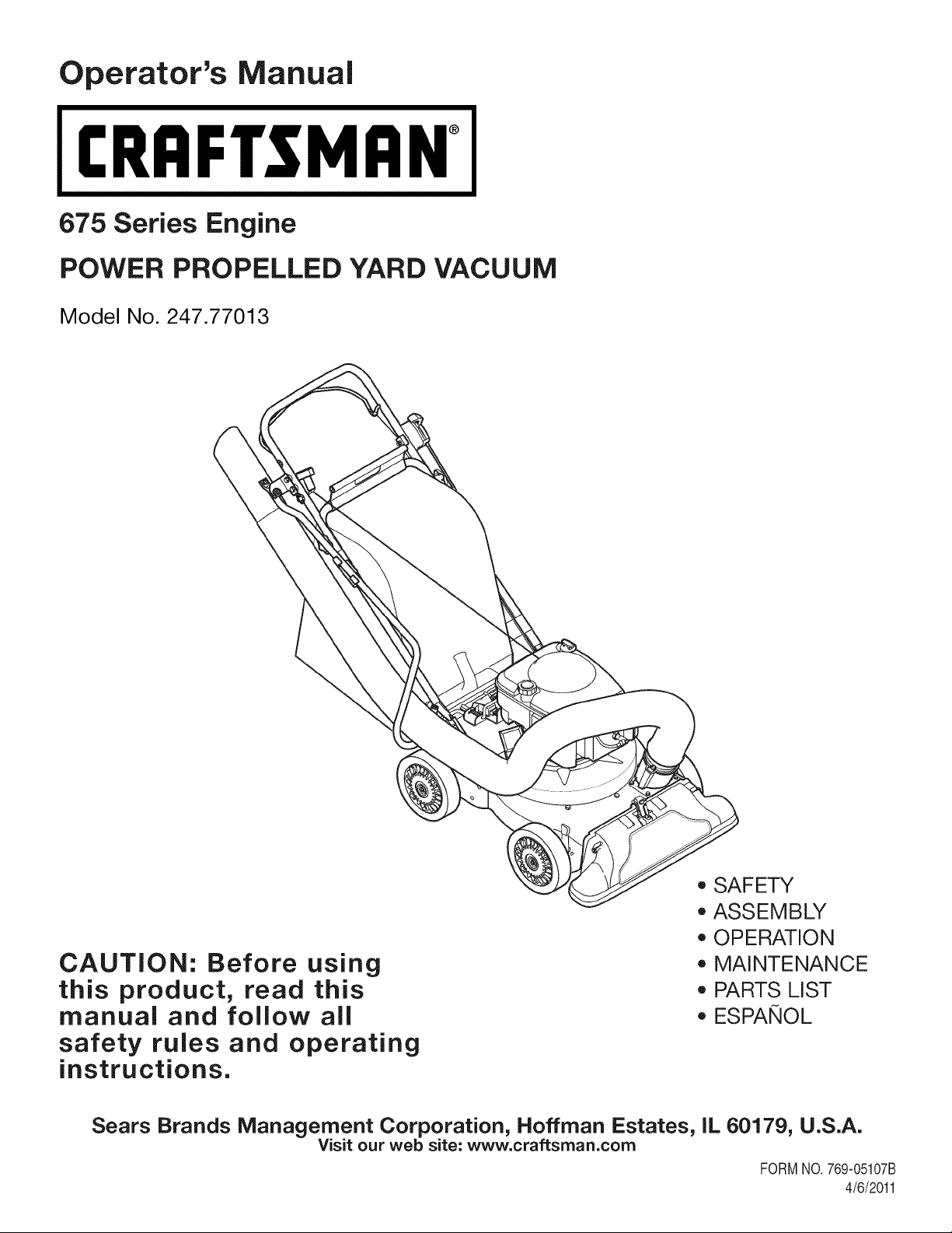
675 Series Engine
POWER PROPELLED YARD VACUUM
Model No. 247.77013
CAUTION: Before using
this product, read this
manual and follow all
safety rules and operating
instructions.
o SAFETY
o ASSEMBLY
o OPERATION
o MAINTENANCE
o PARTS LIST
o ESPANOL
Sears Brands Management Corporation, Hoffman Estates, IL 60179, U.S.A.
Visit our web site: www.craftsman.com
FORMNO.769-05107B
4/6/2011
WarrantyStatement..................................Page2
SafeOperation Practices .......................... Page 3
Safety Labels ............................................ Page 7
Assembly .................................................. Page 8
Operation .................................................. Page 12
Service and Maintenance ......................... Page 16
Off-Season Storage .................................. Page 22
Trouble Shooting ....................................... Page 23
Parts List ................................................... Page 24
Repair Protection Agreement ................... Page 38
Espa_ol ..................................................... Page 39
Service Numbers ...................................... Back Cover
CRAFTSMAN TWO YEAR FULL WARRANTY
FORTWOYEAR(S)fromthe dateof purchase,this productiswarrantedagainstanydefectsinmaterialorworkmanship.A defectiveproductwill
receivefree repairor replacementif repairis unavailable.
Forwarrantycoveragedetailsto obtainfree repairor replacement,visitthe web site:www.craftsman.com
ThiswarrantycoversONLYdefectsin materialandworkmanship.Warrantycoveragedoes NOTinclude:
• Expendableitemsthatcan wearout fromnormaluse withinthe warrantyperiod,suchas the blades, sparkplug,aircleaner,flail
screenand catcherbag.
• Productdamageresultingfrom userattemptsat productmodificationor repairor causedby productaccessories.
• Repairsnecessarybecauseof accidentor failureto operateormaintainthe productaccordingto all suppliedinstructions.
• Preventivemaintenance,or repairsnecessarydueto improperfuel mixture,contaminatedor stalefuel.
Thiswarrantyis voidif this productis everusedwhileprovidingcommercialservicesor if rentedto anotherperson.
Thiswarrantygivesyouspecificlegal rights,andyoumayalso haveother rightswhichvaryfromstateto state.
Sears Brands Management Corporation, Hoffman Estates, IL 60179
EngineSeries: 675
EngineOilType: SAE30
EngineOilCapacity: 18ounces
FuelCapacity: 1 1/2 Quarts
SparkPlug: Champion®RJ19LM
SparkPlugGap: .020"
Model Number.................................................................
Serial Number .................................................................
Dateof Purchase.............................................................
Recordthe modelnumber,serialnumber
anddateof purchaseabove
© Sears Brands,LLC 2

Thissymbolpointsout importantsafetyinstructionswhich,if not
followed,couldendangerthe personalsafetyand/orpropertyof
yourselfandothers. Readandfollowall instructionsin this manual
beforeattemptingto operatethismachine.Failureto complywith
theseinstructionsmay resultin personalinjury.Whenyou seethis
symbol,HEEDITSWARNING!
CALIFORNIA PROPOSITION 65
EngineExhaust,someof its constituents,andcertainvehicle
componentscontainor emit chemicalsknownto Stateof California
to causecancerandbirthdefectsorother reproductiveharm.
Thismachinewas built to be operatedaccordingto the safeopera-
tion practicesin this manual.As withany typeof powerequipment,
carelessnessor error on the part of the operatorcan resultin
seriousinjury.Thismachineis capableof amputatingfingers,hands,
toesandfeetandthrowingdebris.Failureto observethe following
safetyinstructionscouldresultin seriousinjuryordeath.
Your Responsibility--Restrictthe use of thispowermachineto
personswho read,understandandfollowthewarningsand instruc-
tionsin thismanualandon the machine.
SAVETHESEINSTRUCTIONS!
TRAINING
• Read,understand,andfollowall instructionson the machineand
in themanualbeforeattemptingto assembleandoperate.Keep
thismanualina safeplacefor futureandregularreferenceandfor
orderingreplacementparts.
• Readthe Operator'sManualand followall warningsand safety
instructions.Failureto do so can resultin seriousinjuryto the
operatorand/orbystanders.Forquestionscall, 1-800-4MY-
HOME.
• Be familiarwith all controlsand their properoperation.Knowhow
to stopthe machineand disengagethemquickly.
• Neverallowchildrenunder 16 yearsof age to operatethis
machine.Children16andovershouldreadandunderstandthe
instructionsand safe operationpracticesin thismanualandon
the machineand be trainedandsupervisedby anadult.
• Neverallowadultsto operatethis machinewithoutproper
instruction.
• Keepbystanders,pets,andchildrenat least75feetfromthe
machinewhile it is in operation.Stopmachineif anyoneenters
the area.
• Neverrun an engine indoorsor in a poorlyventilatedarea.Engine
exhaustcontainscarbonmonoxide,anodorlessanddeadlygas.
• Do not puthandsand feet near rotatingpartsor in the feeding
chambersanddischargeopening.Contactwiththe rotating
impellercan amputatefingers,hands,and feet.
• Neverattemptto unclogeitherthe feed intakeor discharge
opening,removeor emptybag,or inspectand repairthe machine
whilethe engineis running.Shutthe engineoff andwaituntilall
movingpartshavecometo a completestop.Disconnectthe spark
plugwireandgroundit againstthe engine.
PREPARATION
• Thoroughlyinspecttheareawherethe equipmentis to be used.
Removeall rocks,bottles,cans,or otherforeignobjectswhich
could bepickedupor thrownandcausepersonalinjuryor
damageto the machine.
• Alwayswear safetyglassesor safetygogglesduring operation
andwhile performingan adjustmentor repair,to protectyour
eyes.Thrownobjectswhichricochetcan causeseriousinjuryto
the eyes.
• Wearsturdy,rough-soledworkshoesandclose-fittingslacksand
shirts.Loosefittingclothesor jewelrycan becaughtin movable
parts.Neveroperatethis machinein barefeetorsandals.Wear
leatherworkgloveswhenfeedingmaterialinthe chipperchute.
• Beforestarting,checkall bolts and screwsfor propertightnessto
besurethe machineis insafeworkingcondition.Also,visually
inspectmachinefor any damageat frequentintervals.
• Maintainor replacesafetyandinstructionslabels,as necessary.
3

Safe Handling of Gasoline:
Toavoidpersonalinjuryor propertydamageuseextremecare in
handlinggasoline.Gasolineis extremelyflammableand the vaporsare
explosive.Seriouspersonalinjurycan occurwhengasolineis spilled
onyourselfor yourclotheswhichcan ignite.Washyour skinand
changeclothesimmediately.
• Use onlyan approvedgasolinecontainer.
• Neverfill containersinsidea vehicleor ona truckor trailerbed
witha plasticliner.Alwaysplacecontainersonthe groundaway
fromyour vehiclebeforefilling.
• Whenpractical,removegas-poweredequipmentfromthe truck
ortrailerand refuelitonthe ground.Ifthisis notpossible,then
refuelsuchequipmenton a trailerwith a portablecontainer,rather
thanfroma gasolinedispensernozzle.
• Keepthe nozzlein contactwith the rimof the fuel tank or
containeropeningat all times untilfuelingis complete.Do not use
a nozzlelock-opendevice.
• Extinguishall cigarettes,cigars,pipesand other sourcesof
ignition.
• Neverfuel machineindoors.
• Neverremovegas capor addfuel whilethe engineishot or run-
ning.Allowengineto cool at leasttwo minutesbeforerefueling.
• Neveroverfill fueltank. Fill tankto no morethan1/2inchbelow
bottomof filler neckto allowspacefor fuel expansion.
• Replacegasolinecapandtightensecurely.
• If gasolineisspilled,wipe itoff theengineand equipment.Move
unitto anotherarea.Wait5 minutesbeforestartingthe engine.
• To reducefire hazards,keepmachinefreeof grass, leaves,or
otherdebrisbuild-up.Cleanupoil orfuel spillageand removeany
fuel soakeddebris.
• Neverstorethe machineor fuel containerinsidewherethereis an
openflame,sparkor pilotlightas on awaterheater,spaceheater,
furnace,clothesdryer orothergas appliances.
OPERATION
• Do not puthandsand feet near rotatingpartsor in thefeeding
chambersand dischargeopening.Contactwiththe rotating
impellercan amputatefingers,hands,and feet.
• Beforestartingthe machine,makesurethe chipperchute,feed
intake,andcuttingchamberare emptyandfreeof all debris.
• Thoroughlyinspectall materialto be shreddedand removeany
metal,rocks,bottles,cans,or otherforeignobjectswhichcould
causepersonalinjuryor damageto the machine.
• Ifthe impellerstrikesa foreignobjector if yourmachineshould
start makinganunusualnoiseorvibration,immediatelyshut
the engineoff. Allowthe impellerto cometoa completestop.
Disconnectthe sparkplug wire,ground itagainstthe engineand
performthe followingsteps:
a. Inspectfor damage.
b. Repairor replaceanydamagedparts.
c. Checkfor anyloose partsandtightento assurecontinued
safeoperation.
• Donot allowanaccumulationof processedmaterialto build up in
the dischargearea.This can preventproperdischargeandresult
inkickbackof materialthroughthe feedopening.
• Donot attemptto shredorchip materiallargerthanspecified
on the machineor in this manual.Personalinjuryor machine
damagecould result.
• Neverattemptto unclogeitherthe feedintakeor discharge
openingwhilethe engineis running.Shuttheengineoff,waituntil
all movingpartshavestopped,disconnectthe sparkplugwireand
grounditagainsttheenginebeforeclearingdebris.
• Neveroperatewithoutvacuumbaganddischargechuteproperly
attachedtothe machine.Neveremptyor changevacuumbag
whilethe engineisrunning.Vacuumbagmustbe keptclosedat
all timesduringoperation.
• Neveroperatewithouteitherthe inletnozzleor optionalhose
attachment(if applicable)properlyattachedto the machine.
Neverattemptto attachor changeeitherattachmentwhile the
engineis running.
• Keepallguards,deflectorsand safetydevicesin placeand
operatingproperly.
• Keepyourfaceandbodybackandto the sideof the chipper
chutewhilefeedingmaterialintothe machineto avoidaccidental
kickbackinjuries.
• Neveroperatethis machinewithoutgoodvisibility or light.Always
be sureof yourfootingand keepa firmholdon the handles.
• Donot operatethis machineon a paved,gravelor non-level
surface.
• Donot operatethis machinewhileunderthe influenceof alcohol
or drugs.
• Mufflerand enginebecomehot and cancause a burn.Do not
touch.
• Neverpick uporcarrymachinewhilethe engineis running.
• Ifsituationsoccurwhichare notcoveredinthis manual,use care
andgoodjudgement.ContactCustomerSupportforassistance
andthe nameof the nearestservicedealer.
4
MAINTENANCE & STORAGE
• Nevertamperwith safetydevices.Checktheirproperoperation
regularly.
• Checkboltsand screwsfor propertightnessat frequentintervals
to keepthe machinein safe workingcondition.Also,visually
inspectmachinefor anydamageand repair,if needed.
Beforecleaning,repairing,or inspecting,stopthe engineand
makecertainthe impellerand allmovingpartshavestopped.
Disconnectthe spark plugwire and groundit againstthe engine
to preventunintendedstarting.
Do notchangetheenginegovernorsettingsor overspeedthe
engine.Thegovernorcontrolsthe maximumsafeoperatingspeed
of the engine.
Maintainor replacesafetyand instructionlabels,as necessary.
Followthismanualfor safeloading,unloading,transporting,and
storageof this machine.
Neverstorethe machineorfuel containerinsidewherethereis an
openflame,sparkorpilot lightsuchas a waterheater,furnace,
clothesdryer,etc.
Allowmachineto cool at least 5 minutesbeforestoring.
• Alwaysreferto the operator'smanualfor properinstructionson
off-seasonstorage.
• If thefuel tank hasto be drained,do this outdoors.
• Observeproperdisposallawsand regulationsfor gas, oil,etc. to
protectthe environment.
• Accordingto the ConsumerProductsSafetyCommission(CPSC)
andthe U.S.EnvironmentalProtectionAgency(EPA),this product
hasan Average UsefulLifeof seven(7)years,or 60hoursof
operation.At the end of theAverageUsefulLifehavethe machine
inspectedannuallybyan authorizedservicedealerto ensurethat
allmechanicalandsafetysystemsare workingproperlyand not
wornexcessively.Failureto do so can resultinaccidents,injuries
ordeath.
DO NOT MODIFY ENGINE
Toavoidseriousinjuryordeath,donot modifyenginein anyway.
Tamperingwiththe governorsettingcan leadto a runawayengineand
causeit to operateat unsafespeeds.Nevertamperwithfactorysetting
of enginegovernor.
NOTICE REGARDING EMISSIONS
Engineswhich are certifiedtocomplywith Californiaandfederal
EPAemissionregulationsfor SORE(SmallOff RoadEquipment)are
certifiedto operateon regularunleadedgasoline,and mayinclude
the followingemissioncontrol systems:EngineModification(EM),
OxidizingCatalyst(OC), SecondaryAirInjection(SAI)and ThreeWay
Catalyst(TWO)if so equipped.
SPARK ARRESTOR
Thismachineis equippedwithan internalcombustionengineand
shouldnotbe usedonor nearanyunimprovedforest-covered,
brushcoveredor grass-coveredlandunlessthe engine'sexhaust
systemis equippedwitha sparkarrestormeetingapplicablelocal or
statelaws(if any).
Ifa sparkarrestoris used,it shouldbe maintainedin effectiveworking
orderby theoperator.Inthe Stateof Californiathe aboveis required
bylaw (Section4442of the CaliforniaPublicResourcesCode). Other
statesmayhavesimilarlaws. Federallawsapplyonfederallands.
A sparkarrestorfor the muffleris availablethroughyournearestSears
PartsandRepairServiceCenter.
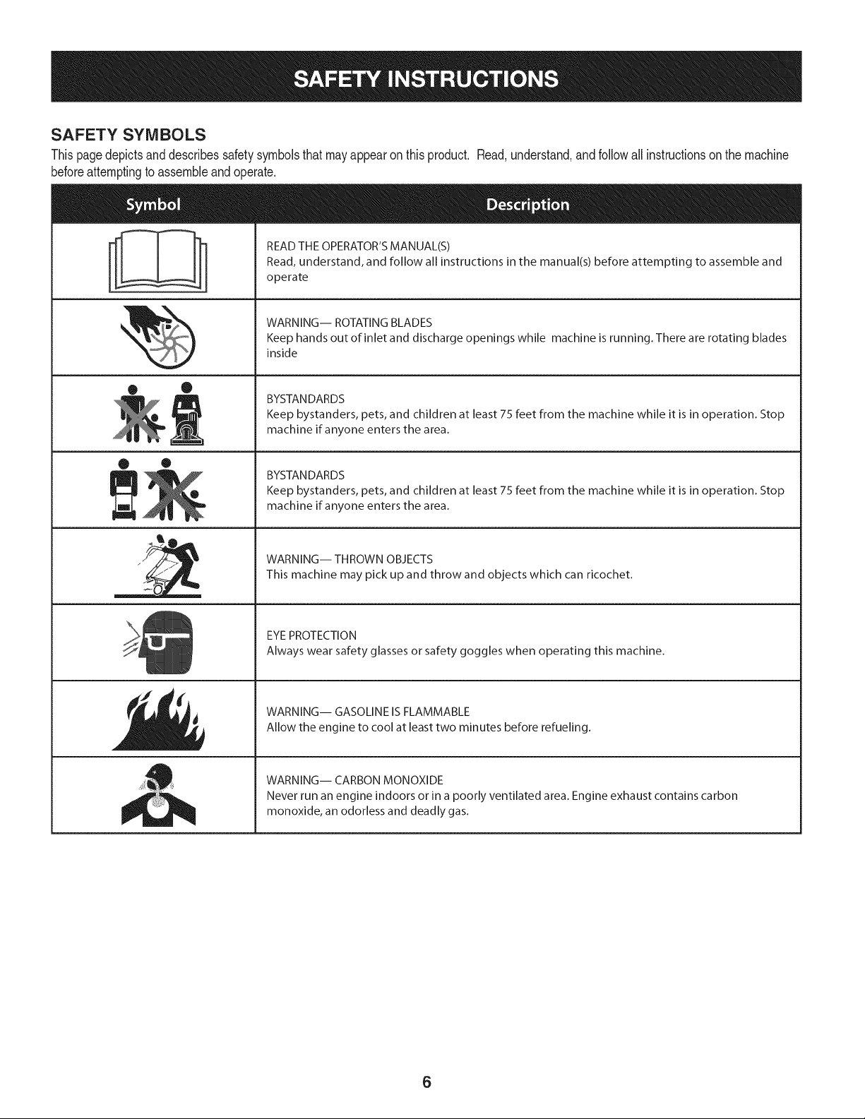
SAFETY SYMBOLS
Thispagedepictsanddescribessafetysymbolsthatmayappearonthisproduct. Read,understand,andfollowall instructionson the machine
beforeattemptingto assembleandoperate.
i
i
• ®
® •
llm
il
READ THE OPERATOR'S MANUAL(S)
Read, understand, and follow all instructions in the manual(s) before attempting to assemble and
operate
WARNING-- ROTATING BLADES
Keep hands out of inlet and discharge openings while machine is running. There are rotating blades
inside
BYSTAN DARDS
Keep bystanders, pets, and children at least 75 feet from the machine while it is in operation. Stop
machine if anyone enters the area.
BYSTAN DARDS
Keep bystanders, pets, and children at least 75 feet from the machine while it is in operation. Stop
machine if anyone enters the area.
WARNING-- THROWN OBJECTS
This machine may pick up and throw and objects which can ricochet.
EYE PROTECTION
Always wear safety glasses or safety goggles when operating this machine.
WARNING-- GASOLINE IS FLAMMABLE
Allow the engine to cool at least two minutes before refueling.
WARNING-- CARBON MONOXIDE
Never run an engine indoors or in a poorly ventilated area. Engine exhaust contains carbon
monoxide, an odorless and deadly gas.
6
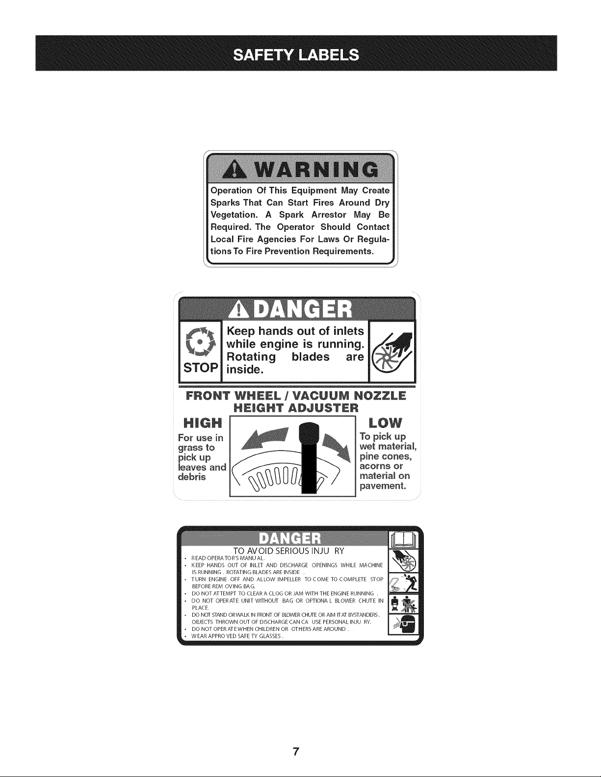
Operation Of This Equipment May Create
Sparks That Can Start Fires Around Dry
Vegetation. A Spark Arrestor May Be
Required. The Operator Should Contact
Local Fire Agencies For Laws Or Regula=
tions To Fire Prevention Requirements.
STOP
Keep hands out of inlets
while engine is running.
Rotating blades are
inside.
FRONT WHEEL / VACUUM NOZZLE
HEmGHT ADJUSTER
For use in
grass to
pickup
_eaves and
debris
To pick up
wet material
pine cones_
acorns Or
materia_ on
pavement.
TO AVOID SERIOUSINJU RY
R EAD OPERA TO R'S MANU AL.
KEEP HANDS OUT OF INLET AND DISCHARGE OPENINGS WHILE MACHINE
IS RUNNING . ROTATING BLADES ARE INSIDE .
TURN ENGINE OFF AND ALLOW IMPELLER TOCOME TOCOMPLETE STOP
BEFORE REM OVlNG BAG.
DO NOT ATTEMPT TO CLEAR A CLOG OR JAM WITH THE ENGINE RUNNING .
DO NOT OPERATE UNIT WITHOUT BAG OR OPTIONA L BLOWER CHUTE IN
PLACE.
DO NOT STAND ORWALK IN FRONT OF BLOWER CHUTE OR AIM ITAT BYSTANDERS.
OBJECTS THROWN OUT OF DISCHARGE CAN CA USE PERSONAL INJU RY.
DO NOT OPERATEWHEN CHILDREN OR OTHERS ARE AROUND .
WEAR APPRO VED SAFE TY GLASSES.
7
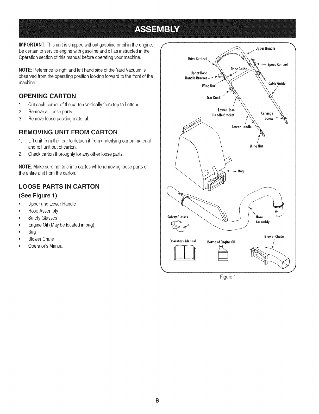
IMPORTANT:Thisunit isshippedwithoutgasolineoroil inthe engine.
Becertainto serviceenginewithgasolineandoilas instructedin the
Operationsectionof this manualbeforeoperatingyourmachine.
NOTE:Referenceto rightand left hand sideof the YardVacuumis
observedfrom the operatingpositionlookingforwardto the frontof the
machine.
OPENING CARTON
1. Cut eachcornerof the cartonverticallyfromtop to bottom.
2. Removeall looseparts.
3. Removeloosepackingmaterial.
REMOVING UNIT FROM CARTON
1. Lift unit from the rearto detach it from underlyingcartonmaterial
androllunit out of carton.
2. Checkcarton thoroughlyfor anyotherlooseparts.
NOTE:Makesurenot to crimpcableswhile removingloosepartsor
theentire unitfromthecarton.
LOOSE PARTS IN CARTON
(See Figure 1)
* Upperand LowerHandle
. HoseAssembly
* SafetyGlasses
. EngineOil(Maybelocatedinbag)
* Bag
. BlowerChute
* Operator'sManual
f
Safety Glasses
Operator'sManual
Bottle of EngineOil
Figure1
\
Hose
Assembly
Blower Chute
J
8
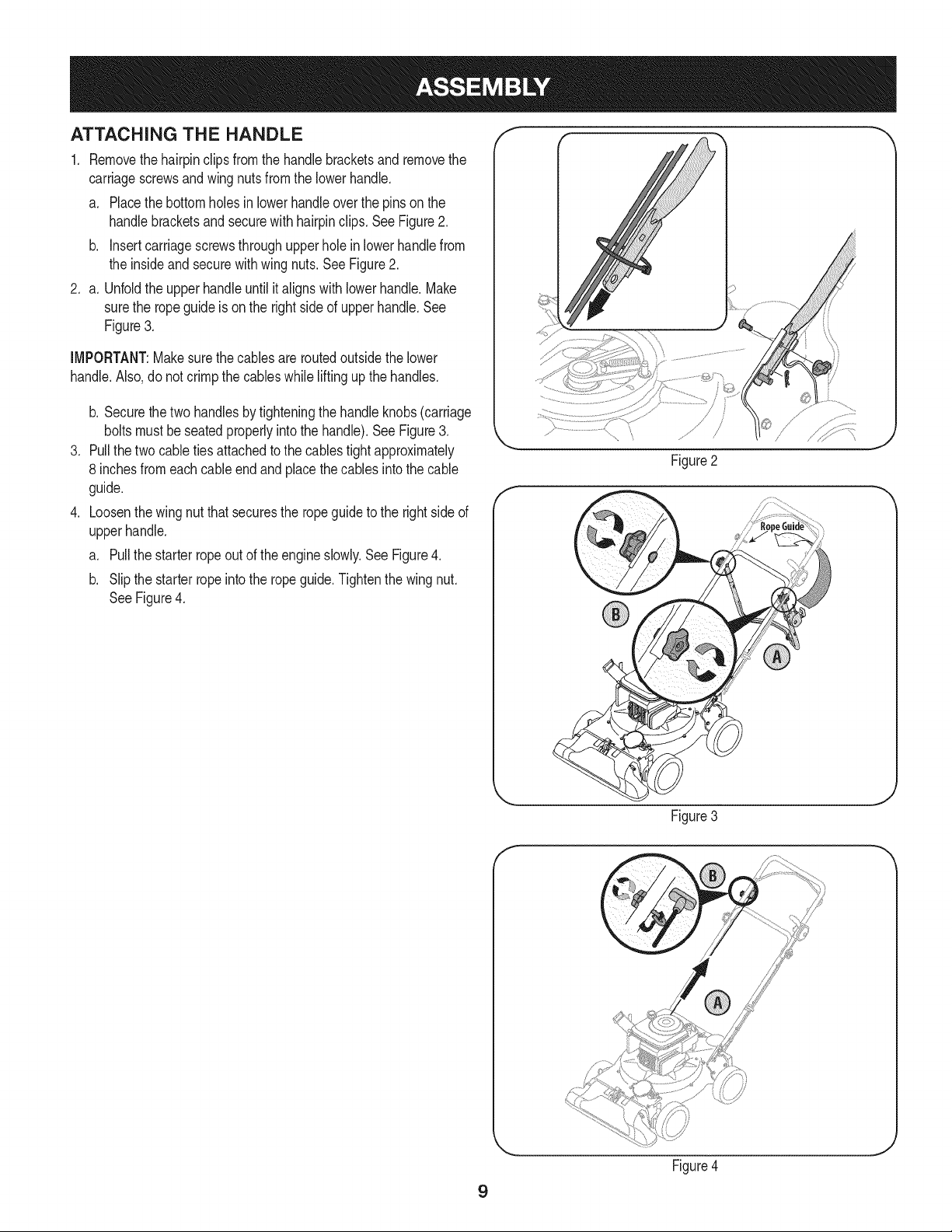
ATTACHING THE HANDLE
1. Removethehairpinclips from the handlebracketsand removethe
carriagescrewsandwingnutsfromthe lowerhandle.
a. Placethe bottomholesin lowerhandleoverthe pinson the
handlebracketsand securewith hairpinclips. See Figure2.
b. insert carriagescrewsthroughupperholein lowerhandlefrom
the insideandsecurewithwingnuts.SeeFigure2.
2. a. Unfoldthe upperhandleuntil italignswithlowerhandle.Make
surethe ropeguideis onthe rightside of upperhandle.See
Figure3.
IMPORTANT:Makesurethe cablesareroutedoutsidethe lower
handle.Also,donot crimpthe cableswhile liftingupthe handles.
.
.
b. Securethe two handlesbytighteningthe handleknobs(carriage
boltsmustbeseatedproperlyintothe handle).See Figure3.
Pullthetwo cabletiesattachedto the cablestightapproximately
8 inchesfromeachcableendandplacethe cablesintothe cable
guide.
Loosenthe wingnut thatsecuresthe ropeguideto the rightsideof
upperhandle.
a. Pull the starterropeout of the engineslowly.See Figure4.
b. Slip the starterropeinto the ropeguide.Tightenthe wingnut.
SeeFigure4.
Figure2
Figure3
J
9
Figure4
J
f
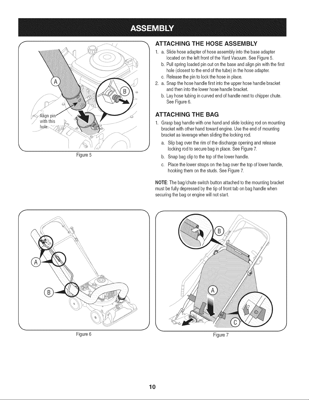
Figure5
_, ATTACHING THE HOSE ASSEMBLY
1. a. Slidehoseadapterof hoseassemblyintothe baseadapter
locatedon the left front of theYardVacuum.SeeFigure5.
b. Pullspringloadedpinout on the baseandalignpinwiththe first
hole(closestto the end of the tube) in the hoseadapter.
c. Releasethe pinto lockthe hosein place.
2. a. Snapthe hosehandlefirst intothe upperhose handlebracket
andthen intothe lowerhosehandlebracket.
b. Layhosetubingincurvedendof handlenextto chipperchute.
SeeFigure6.
ATTACHING THE BAG
Graspbaghandlewithonehandandslide lockingrodonmounting
bracketwith otherhandtowardengine.Usethe endof mounting
bracketas leveragewhenslidingthe lockingrod.
a. Slip bag overthe rim of the dischargeopeningandrelease
lockingrodto securebagin place.SeeFigure7.
b. Snap bag clipto the topof the lowerhandle.
c. Placethe lowerstrapson the bagoverthe topof lowerhandle,
hookingthemon the studs.SeeFigure7.
NOTE:The bag/chuteswitchbuttonattachedto the mountingbracket
must befullydepressedby thetip of fronttab on baghandlewhen
securingthe bagorenginewill not start.
Figure6
Figure7
10
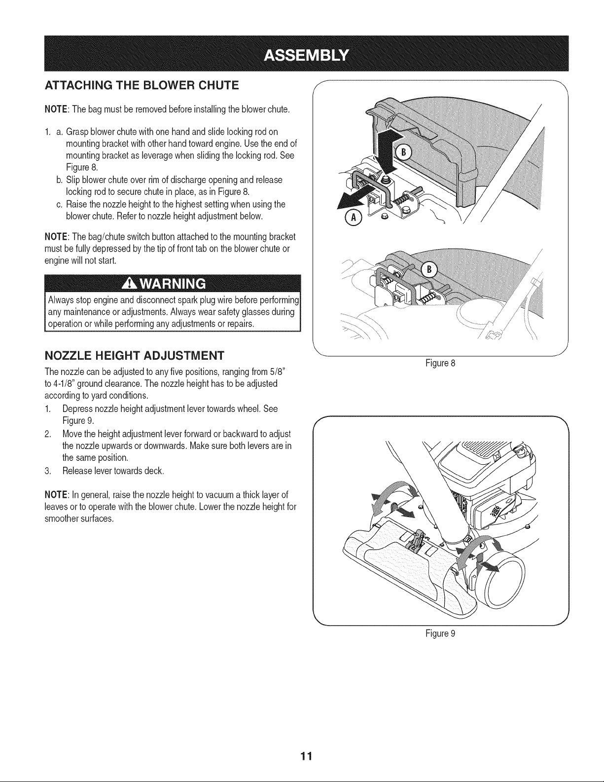
ATTACHING THE BLOWER CHUTE f
NOTE:Thebagmust beremovedbeforeinstallingthe blowerchute.
1. a. Graspblowerchutewith one handand slide lockingrod on
mountingbracketwith otherhandtowardengine.Usethe endof
mountingbracketas leveragewhenslidingthe lockingrod.See
Figure8.
b. Slipblowerchuteoverrimof dischargeopeningandrelease
lockingrodto securechute in place,as in Figure8.
c. Raisethe nozzleheightto the highestsettingwhen usingthe
blowerchute.Referto nozzleheightadjustmentbelow.
NOTE:Thebag/chuteswitchbuttonattachedto the mountingbracket
mustbefullydepressedbythe tip of fronttab onthe blowerchuteor
enginewill not start.
Alwaysstopengineanddisconnectsparkplugwire beforeperforming
any maintenanceor adjustments.Alwayswear safetyglassesduring
operationor whileperformingany adjustmentsor repairs.
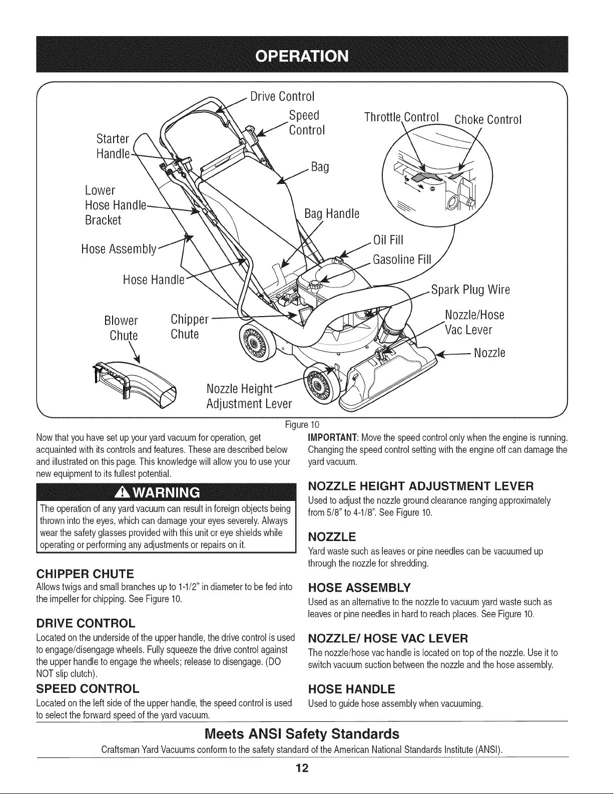
NOZZLE HEIGHT ADJUSTMENT
Thenozzlecan beadjustedto anyfive positions,rangingfrom5/8"
to 4-1/8"groundclearance.The nozzleheighthasto be adjusted
accordingto yardconditions.
1. Depressnozzleheightadjustmentlevertowardswheel.See
Figure9.
2. Movethe heightadjustmentleverforwardor backwardto adjust
the nozzleupwardsor downwards.Makesure bothleversarein
the sameposition.
3. Releaselevertowardsdeck.
NOTE:In general,raisethe nozzleheightto vacuuma thicklayerof
leavesorto operatewiththeblowerchute.Lowerthe nozzleheightfor
smoothersurfaces.
f
\\
Figure8
J
Figure9
J
11
f
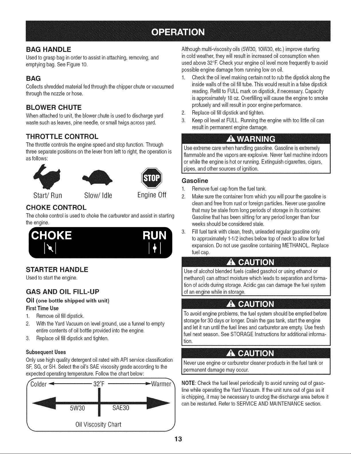
Drive Control
Speed Thr( Control Choke Control
Starter
Lower
Hose
Bracket
HoseAssembl'
Hose
Blower Chipper
Chute Chute
Bag
Bag Handle
Oil Fill
Gasoline Fill
)ark Plug Wire
Nozzle/Hose
Lever
Nozzle
Nowthat youhavesetup youryardvacuumfor operation,get
acquaintedwith itscontrolsandfeatures.Thesearedescribedbelow
andillustratedon this page.This knowledgewill allowyou to useyour
newequipmentto its fullestpotential.
Theoperationof anyyard vacuumcan resultinforeignobjectsbeing
thrownintothe eyes,whichcan damageyoureyesseverely.Always
I wearthe safetyglassesprovidedwiththisunit oreye shieldswhile
[operatingor performinganyadjustmentsor repairson it.
Nozzle Heig
Adjustment Lever
Figure10
iMPORTANT:Movethe speedcontrolonly whenthe engineis running.
Changingthe speedcontrolsettingwiththeengineoff can damagethe
yardvacuum.
CHIPPER CHUTE
Allowstwigsandsmallbranchesup to 1-1/2"in diameterto be fed into
the impellerfor chipping.See Figure10.
DRIVE CONTROL
Locatedon the undersideof the upperhandle,the drivecontrolis used
to engage/disengagewheels.Fullysqueezethe drivecontrolagainst
the upperhandleto engagethe wheels;releaseto disengage.(DO
NOTslip clutch).
SPEED CONTROL
Locatedon the left side of the upperhandle,the speedcontrolis used
to selectthe forwardspeedof the yardvacuum.
NOZZLE HEIGHT ADJUSTMENT LEVER
Usedto adjustthe nozzlegroundclearancerangingapproximately
from5/8" to 4-1/8".See Figure10.
NOZZLE
Yardwastesuchas leavesorpineneedlescan bevacuumedup
throughthe nozzlefor shredding.
HOSE ASSEMBLY
Usedas analternativeto thenozzleto vacuumyardwastesuchas
leavesor pineneedlesin hardto reachplaces.SeeFigure10.
NOZZLE/HOSE VAC LEVER
The nozzle/hosevac handleis locatedon topof the nozzle.Useit to
switchvacuumsuctionbetweenthe nozzleandthe hoseassembly.
HOSE HANDLE
Usedto guidehoseassemblywhenvacuuming.
Meets ANSI Safety Standards
CraftsmanYardVacuumsconformto the safetystandardof the AmericanNationalStandardsinstitute(ANSi).
12
BAG HANDLE
Usedto grasp baginorderto assistinattaching,removing,and
emptyingbag.SeeFigure10.
BAG
Collectsshreddedmaterialfed throughthe chipperchuteorvacuumed
throughthe nozzleor hose.
BLOWER CHUTE
Whenattachedto unit,the blowerchuteisusedto dischargeyard
wastesuchas leaves,pineneedle,or smalltwigsacrossyard.
THROTTLE CONTROL
Thethrottlecontrolsthe enginespeedandstopfunction.Through
threeseparatepositionson the leverfromleftto right,the operationis
as follows:
Althoughmulti-viscosityoils (5W30,10W30,etc.) improvestarting
incoldweather,theywill resultin increasedoil consumptionwhen
usedabove32°E Checkyourengineoil levelmorefrequentlyto avoid
possibleenginedamagefrom runninglow onoil.
1. Checkthe oil level makingcertainnotto rubthedipstickalongthe
insidewallsof the oilfill tube.Thiswouldresultin afalsedipstick
reading.Refillto FULLmarkondipstick,if necessary.Capacity
isapproximately18oz. Overfillingwill causethe engineto smoke
profuselyand will resultin poor engineperformance.
2. Replaceoil fill dipstickandtighten.
3. Keepoillevelat FULL.Runningthe enginewithtoo littleoil can
resultin permanentenginedamage.
Useextremecarewhen handlinggasoline.Gasolineis extremely
flammableand thevaporsare explosive.Neverfuel machineindoors
or whilethe engineis hot or running.Extinguishcigarettes,cigars,
pipes,andother sourcesof ignition.
Start/Run Slow/Idle Engine Off
CHOKE CONTROL
Thechokecontrolis usedto chokethe carburetorandassistinstarting
the engine.
STARTER HANDLE
Usedto startthe engine.
GAS AND OiL FILL-UP
Oil (one bottle shipped with unit)
First TimeUse
1. Removeoil fill dipstick.
2. With theYardVacuumon levelground,usea funnelto empty
entirecontentsof oil bottle providedintothe engine.
3. Replaceoil fill dipstickand tighten.
Subsequent Uses
Onlyuse highqualitydetergentoil ratedwithAPIserviceclassification
SF,SG,or SH.Selectthe oil'sSAEviscositygradeaccordingto the
expectedoperatingtemperature.Followthe chart below:
/_Colder_ 32°F _Warme_
0il Viscosity Chart
J
Gasoline
1. Removefuel capfromthe fueltank.
2. Makesurethe containerfromwhichyou will pourthe gasolineis
cleanandfree fromrustorforeignparticles.Neverusegasoline
thatmaybe stalefromlongperiodsof storageinitscontainer.
Gasolinethat has been sittingfor any periodlongerthan four
weeksshouldbeconsideredstale.
3. Fillfuel tankwithclean,fresh,unleadedregulargasolineonly
to approximately1-1/2inchesbelowtopof neckto allowfor fuel
expansion.Do notuse gasolinecontainingMETHANOL.Replace
fuel cap.
Useof alcoholblendedfuels(calledgasoholor usingethanolor
methanol)canattract moisturewhichleadsto separationand forma-
tion of acidsduringstorage.Acidicgascan damagethe fuelsystem
of anenginewhilein storage.
Toavoidengineproblems,thefuel systemshouldbeemptiedbefore
storagefor30 daysorlonger.Drainthe gas tank,start theengine
andlet it rununtilthe fuel linesandcarburetorare empty.Usefresh
I fuel nextseason.SeeSTORAGEInstructionsforadditionalinforma-
_tion.
mayoccur.
NOTE:Checkthe fuellevel periodicallyto avoidrunningout of gaso-
linewhile operatingthe YardVacuum.If the unit runsout of gas as it
ischipping,it maybe necessaryto unclogthe dischargeareabeforeit
can be restarted.Referto SERVICEANDMAINTENANCEsection.
13
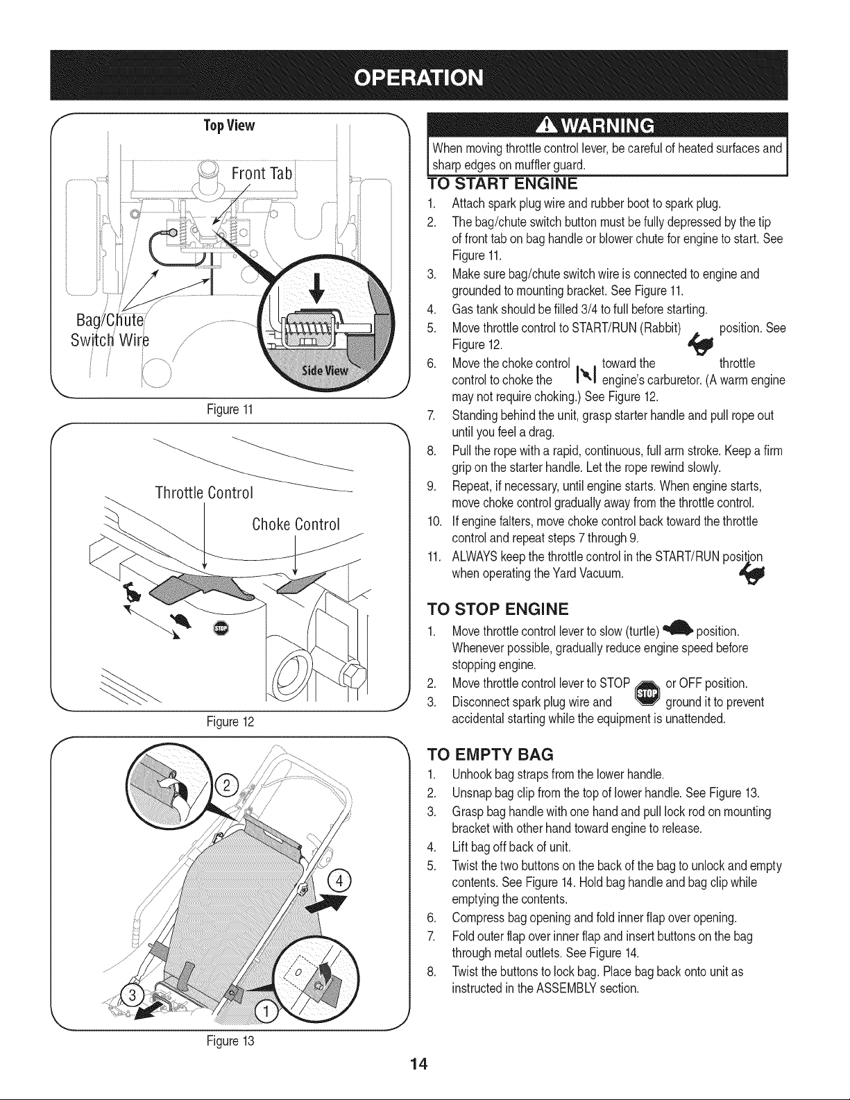
TopView
iiii_ FrontTab i i
BagYC_hutei/
Switch Wire /
/
/
Figure11
Choke Control
Figure12
f
;/
Whenmovingthrottlecontrollever,becarefulof heatedsurfacesand
sharpedgeson mufflerguard.
TO START ENGINE
1. Attachspark plugwire and rubberbootto sparkplug.
2. The bag/chuteswitch buttonmustbefullydepressedbythe tip
of fronttab on baghandleor blowerchutefor engineto start.See
Figure11.
3. Makesurebag/chuteswitchwire is connectedto engineand
groundedto mountingbracket.SeeFigure11.
4. Gas tank shouldbe filled3/4 to full beforestarting.
5. Movethrottlecontrolto START/RUN(Rabbit) position.See
Figure12. _lf
6. Movethechokecontrol towardthe throttle
controltochokethe I",1eng ne'scarburetor(Awarmengine
maynot requirechoking.)See Figure12.
7. Standingbehindthe unit, graspstarterhandleandpull ropeout
until youfeel adrag.
8. Pullthe ropewitha rapid,continuous,full arm stroke.Keepa firm
gripon the starterhandle.Letthe roperewindslowly.
9. Repeat,if necessary,untilenginestarts.Whenenginestarts,
movechokecontrolgraduallyawayfromthe throttlecontrol.
10. If enginefalters,movechoke controlbacktowardthe throttle
controland repeatsteps7 through9.
11. ALWAYSkeepthe throttlecontrolin the START/RUNposition
whenoperatingthe YardVacuum.
TO STOP ENGINE
1. Movethrottlecontrolleverto slow(turtle) _ position.
Wheneverpossible,graduallyreduceenginespeedbefore
stoppingengine.
2. Movethrottlecontrolleverto STOP or OFFposition.
3. Disconnectsparkplugwireand groundit to prevent
accidentalstartingwhilethe equipmentis unattended.
TO EMPTY BAG
1. Unhookbagstrapsfromthe lowerhandle.
2. Unsnapbagclip fromthetop of lowerhandle.See Figure13.
3. Graspbag handlewith one handandpulllock rodonmounting
bracketwith otherhandtowardengineto release.
4. Liftbagoffbackof unit.
5. Twistthe two buttonson the back of the bagto unlockandempty
contents.SeeFigure14.Holdbaghandleandbagclip while
emptyingthe contents.
6. Compressbagopeningand fold innerflap overopening.
7. Foldouter flapoverinnerflapand insertbuttonsonthe bag
throughmetaloutlets.SeeFigure14.
8. Twistthe buttonsto lock bag.Placebagbackonto unitas
instructedinthe ASSEMBLYsection.
Figure13
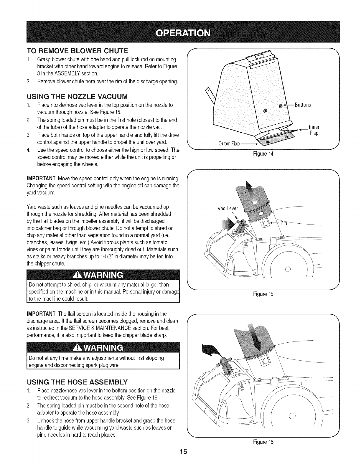
TO REMOVE BLOWER CHUTE
1. Graspblowerchute withone handandpull lockrodonmounting
bracketwithotherhandtowardengineto release.Referto Figure
8 inthe ASSEMBLYsection.
2. Removeblowerchutefrom overthe rim of the dischargeopening.
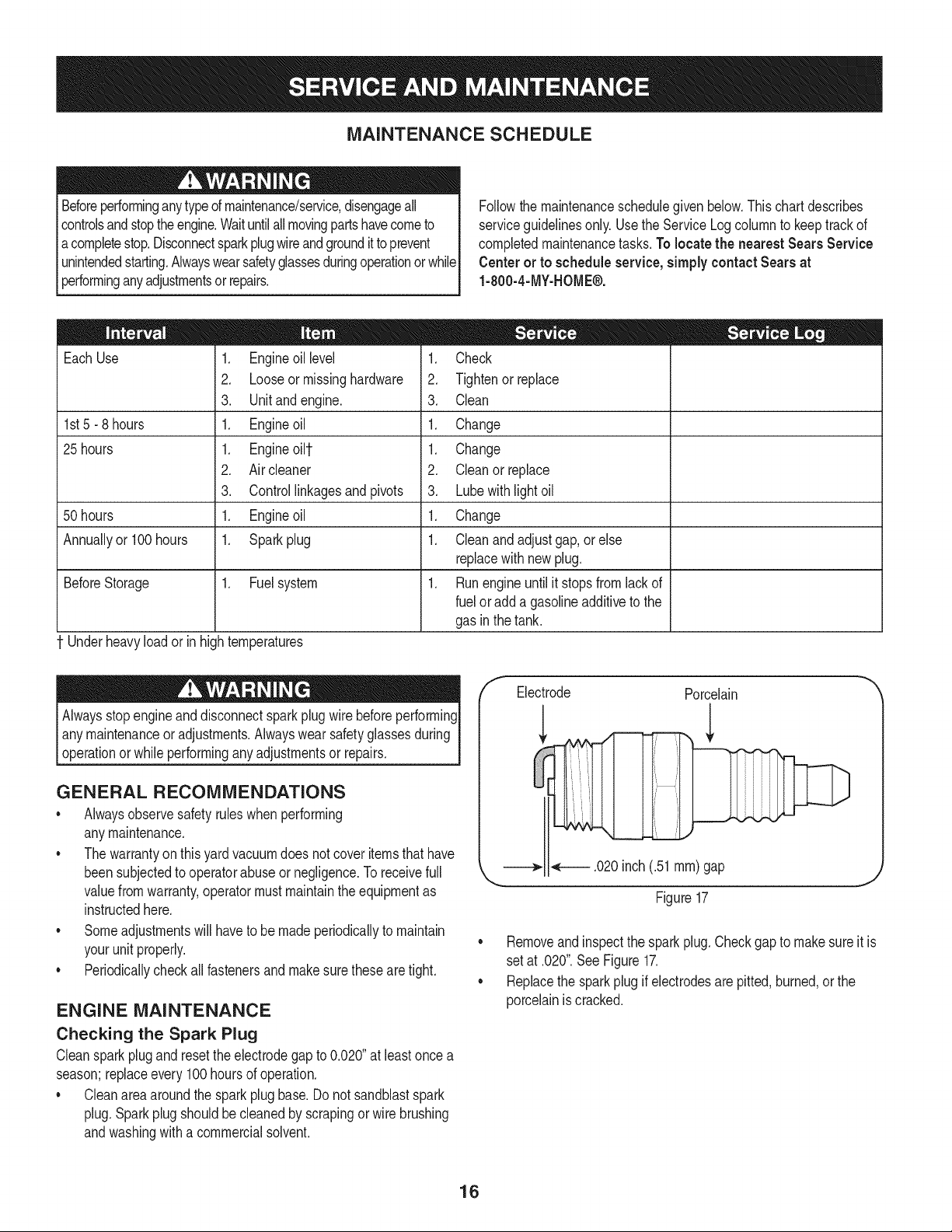
USING THE NOZZLE VACUUM
1. Placenozzle/hosevacleverinthe top positionon the nozzleto
vacuumthroughnozzle.SeeFigure15.
2. Thespringloaded pin mustbe in the first hole(closestto the end
of the tube)of the hoseadapterto operatethe nozzlevac.
3. Placebothhandson top of the upperhandleandfullyliftthe drive
controlagainstthe upperhandleto propelthe unitoveryard.
4. Use the speedcontrolto chooseeitherthe highor low speed.The
speedcontrolmaybemovedeitherwhilethe unitis propellingor
beforeengagingthewheels.
Inner
Flap
OuterFla[:
Figure14
IMPORTANT:Movethe speedcontrolonlywhenthe engineis running.
Changingthe speedcontrolsettingwith the engineoff candamagethe
yardvacuum.
Yardwastesuchas leavesandpineneedlescan bevacuumedup
throughthe nozzlefor shredding.Aftermaterialhas beenshredded
by theflail bladesonthe impellerassembly,it will bedischarged
intocatcherbagorthroughblowerchute.Do notattemptto shredor
chipany materialotherthan vegetationfoundin a normalyard(i.e.
branches,leaves,twigs,etc.)Avoidfibrousplantssuchas tomato
vinesor palmfrondsuntiltheyare thoroughlydriedout. Materialssuch
as stalksor heavybranchesupto 1-1/2"in diametermaybe fed into
the chipperchute.
Vac Lever
specifiedonthe machineorin thismanual.Personalinjuryor
to the machinecould result.
IMPORTANT:Theflail screenis locatedinsidethe housinginthe
dischargearea. if the flail screenbecomesclogged,removeand clean
as instructedin the SERVICE&MAINTENANCEsection.Forbest
performance,it is alsoimportantto keepthe chipperbladesharp.
Do notat any timemakeanyadjustmentswithoutfirststopping
engineanddisconnectingsparkplugwire.
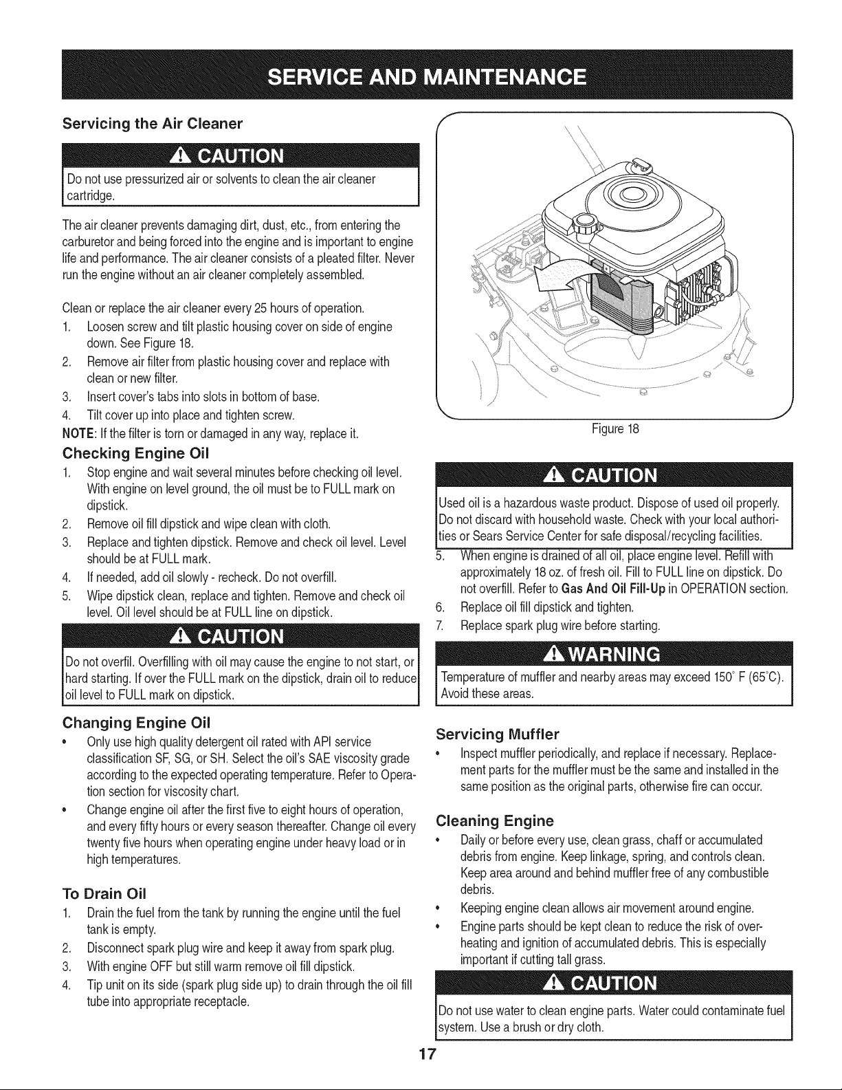
USING THE HOSE ASSEMBLY
1. Placenozzle/hosevacleverinthe bottompositionon the nozzle
to redirectvacuumto the hoseassembly.See Figure16.
2. Thespringloaded pin mustbe in the secondholeof the hose
adapterto operatethe hoseassembly.
3. Unhookthe hosefrom upper handlebracketandgraspthe hose
handleto guidewhilevacuumingyardwastesuchas leavesor
pineneedlesin hardto reachplaces.
Figure15
15
F
Figure16
MAINTENANCE SCHEDULE
Beforeperforminganytypeofmaintenance/service,disengageall
controlsandstoptheengine.Waituntilallmovingpartshavecometo
acompletestop.Disconnectsparkplugwireandgroundit toprevent
unintendedstarting.Alwayswearsafetyglassesduringoperationor while
performinganyadjustmentsor repairs.
Followthe maintenanceschedulegiven below.Thischartdescribes
serviceguidelinesonly.Usethe ServiceLogcolumnto keeptrackof
completedmaintenancetasks.To locate the nearest Sears Service
Centeror to scheduleservice,simplycontactSearsat
1-800-4-MY-HOME®.
EachUse
1st5 - 8 hours
25 hours
50 hours
Annuallyor 100hours
BeforeStorage 1. Fuelsystem
Underheavyloador inhightemperatures
1. Engineoil level
2. Looseor missinghardware
3. Unit and engine.
1. Engineoil
1. Engineoilt
2. Air cleaner
3. Controllinkagesand pivots
1. Engineoil
1. Sparkplug
= =
1. Check
2. Tightenor replace
3. Clean
1. Change
1. Change
2. Cleanor replace
3. Lubewith light oil
1. Change
1. Cleanand adjust gap,orelse
replacewithnewplug.
1. Runengineuntilit stopsfrom lack of
fuelor adda gasolineadditiveto the
gasin thetank.
Alwaysstopengineanddisconnectsparkplugwire beforeperforming
I anymaintenanceor adjustments.Alwayswear safetyglassesduring
[operationor whileperforminganyadjustmentsor repairs.
GENERAL RECOMMENDATIONS
• Alwaysobservesafetyruleswhenperforming
anymaintenance.
• Thewarrantyon this yardvacuumdoes notcover itemsthat have
beensubjectedto operatorabuseor negligence.To receivefull
valuefromwarranty,operatormustmaintaintheequipmentas
instructedhere.
• Someadjustmentswillhaveto be madeperiodicallyto maintain
yourunit properly.
• Periodicallycheckall fastenersand makesurethesearetight.
ENGINE MAINTENANCE
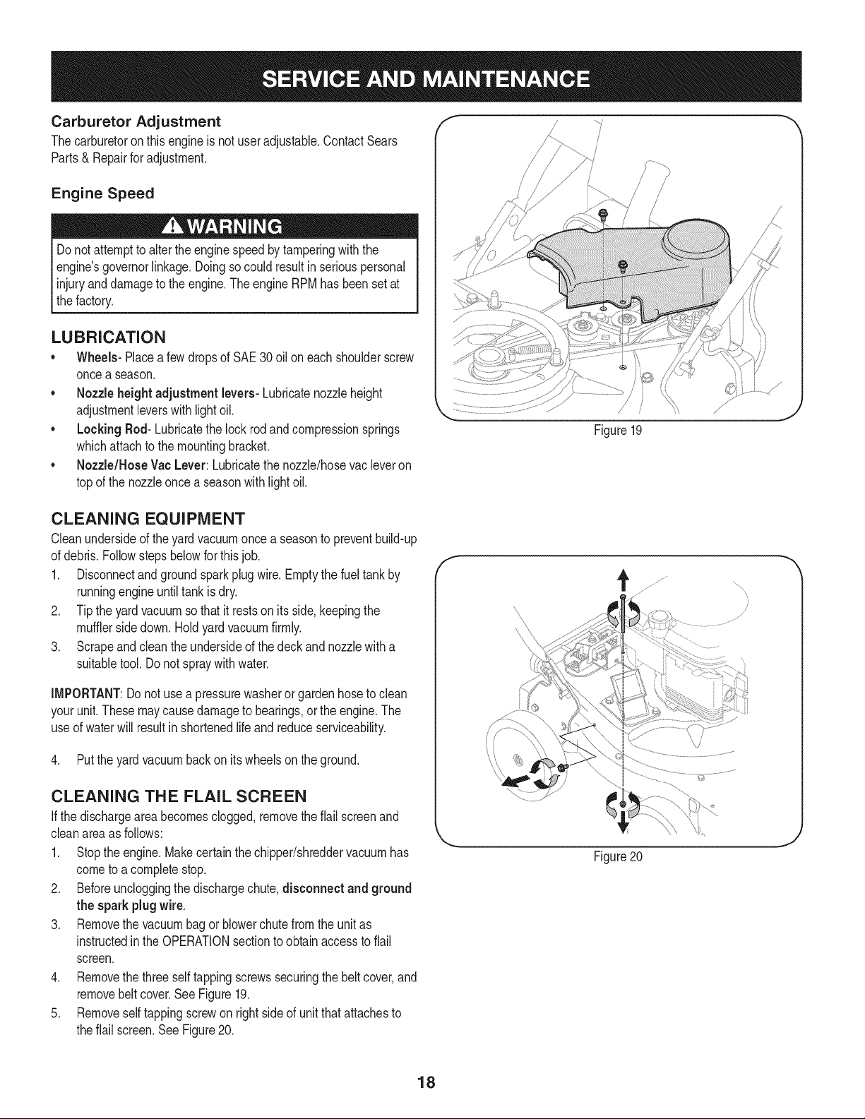
Checking the Spark Plug
Cleansparkplugandresettheelectrodegapto 0.020"at leastonce a
season;replaceevery100hoursof operation.
• Cleanareaaroundthe spark plug base.Do not sandblastspark
plug.Sparkplugshouldbecleanedby scrapingorwire brushing
andwashingwith a commercialsolvent.
/f Electrode Porcelain
.020inch(.51ram)gap
Figure17
J
Removeand inspectthe sparkplug.Checkgap to make sureit is
setat .020".SeeFigure17.
• Replacethe sparkplugif electrodesare pitted,burned,or the
porcelainis cracked.
16
Servicing the Air Cleaner
Do notuse pressurizedair or solventsto cleanthe aircleaner
cartridge.
Theair cleanerpreventsdamagingdirt, dust,etc.,fromenteringthe
carburetorand beingforcedintothe engineandis importantto engine
life andperformance.Theair cleanerconsistsof a pleatedfilter. Never
runthe enginewithoutan aircleanercompletelyassembled.
Cleanor replacetheair cleanerevery25hoursof operation.
1. Loosenscrewand tilt plastichousingcoveron sideof engine
down.SeeFigure18.
2. Removeair filter from plastichousingcover and replacewith
cleanor newfilter.
3. insert cover'stabsinto slotsin bottomof base.
4. Tilt cover up into placeand tighten screw.
NOTE:Ifthe filteris torn ordamagedin anyway,replaceit.
Checking Engine Oil
1. Stopengineand wait severalminutesbeforecheckingoil level.
Withengineonlevelground,the oil mustbeto FULLmarkon
dipstick.
2. Removeoil fill dipstickand wipeclean with cloth.
3. Replaceandtightendipstick.Removeandcheckoil level.Level
shouldbeat FULLmark.
4. If needed,add oil slowly- recheck.Do notoverfill.
5. Wipedipstickclean, replaceand tighten.Removeandcheckoil
level.Oil levelshouldbe at FULLlineondipstick.
Donotoverfil.Overfillingwith oil maycause theengineto not start,or
hardstarting.If overthe FULLmarkon thedipstick,drainoilto reduce
oil levelto FULLmarkondipstick.
f
x \
\
©
Figure18
J
Usedoil is a hazardouswasteproduct.Disposeof usedoil properly.
IDo notdiscardwithhouseholdwaste.Checkwithyour localauthori-
_tiesor SearsService Centerfor safedisposal/recyclingfacilities.
5. Whenengineis drainedof all oil, placeenginelevel. Refillwith
approximately18oz. of fresh oil. Fillto FULLline on dipstick.Do
notoverfill.Referto Gas And Oil Fill-Up in OPERATIONsection.
6. Replaceoil fill dipstickandtighten.
7. Replacesparkplugwire beforestarting.
Temperatureof mufflerandnearbyareasmayexceed150° F (65°C).
Avoidtheseareas.
Changing Engine Oil
• Onlyuse high qualitydetergentoil ratedwithAPIservice
classificationSF,SG, orSH.Selecttheoil's SAEviscositygrade
accordingto the expectedoperatingtemperature.Referto Opera-
tion sectionfor viscositychart.
• Changeengineoil afterthe first five to eighthoursof operation,
andeveryfifty hoursoreveryseasonthereafter.Changeoil every
twentyfivehourswhenoperatingengineunderheavyloadorin
hightemperatures.
To Drain Oil
1. Drainthe fuelfrom the tank by runningthe engineuntil thefuel
tankis empty.
2. Disconnectsparkplug wireand keepit away fromspark plug.
3. With engineOFF butstill warm removeoil fill dipstick.
4. Tip uniton its side (sparkplug side up) to drain throughthe oil fill
tubeinto appropriatereceptacle.
Servicing Muffler
• inspectmufflerperiodically,and replaceif necessary.Replace-
mentpartsfor the mufflermustbe the sameandinstalledinthe
samepositionas theoriginalparts,otherwisefirecan occur.
Cleaning Engine
• Dailyor beforeevery use,cleangrass,chaff or accumulated
debrisfromengine.Keeplinkage,spring,andcontrolsclean.
Keepareaaroundand behindmufflerfree of anycombustible
debris.
• Keepingenginecleanallowsair movementaroundengine.
• Enginepartsshouldbekeptcleanto reducethe riskof over-
heatingandignitionof accumulateddebris. This isespecially
importantifcuttingtallgrass.
Donot usewaterto cleanengineparts.Watercouldcontaminatefuel
system.Usea brushor dry cloth.
17
Carburetor Adjustment f ..../ _,
Thecarburetoron this engineis not useradjustable.ContactSears /
Parts& Repairforadjustment,
Engine Speed
Do not,attemptto alterthe enginespeedby tamperingwith the
engines governorlinkage.Doingsocould resultin seriouspersonal
I injuryanddamageto the engine.The engineRPMhasbeensetat
thefactory.
LUBRICATION
• Wheels- Placea few dropsof SAE30 oil on eachshoulderscrew
oncea season.
• Nozzle height adjustment levers- Lubricatenozzleheight
adjustmentleverswith lightoil.
• Locking Rod- Lubricatethe lock rodandcompressionsprings
whichattachto the mountingbracket.
• Nozzle/Hose Vac Lever: Lubricatethe nozzle/hosevac leveron
topof the nozzleonce a seasonwith lightoil.
/
Figure19
CLEANING EQUIPMENT
Cleanundersideof theyardvacuumonce a seasonto preventbuild-up
of debris.Followstepsbelowfor thisjob.
1. Disconnectandgroundsparkplugwire.Emptythe fueltankby
runningengineuntiltankis dry.
2. Tipthe yard vacuumso that it restson its side, keepingthe
mufflersidedown.Holdyardvacuumfirmly.
3. Scrapeand cleanthe undersideof the deckandnozzlewitha
suitabletool.Donot spraywithwater.
IMPORTANT:Donot usea pressurewasherorgardenhoseto clean
yourunit.Thesemaycausedamageto bearings,orthe engine.The
useof waterwill resultin shortenedlife and reduceserviceability.
4. Putthe yardvacuumbackon its wheelson theground.
CLEANING THE FLAIL SCREEN
Ifthe dischargeareabecomesclogged, removetheflail screenand
cleanareaas follows:
1. Stopthe engine.Makecertainthe chipper/shreddervacuumhas
cometo a completestop.
2. Beforeuncloggingthe dischargechute,disconnect and ground
the spark plugwire.
3. Removethe vacuumbagor blowerchutefromthe unitas
instructedin the OPERATIONsectionto obtainaccessto flail
screen.
4. Removethe three selftappingscrewssecuringthebelt cover,and
removebeltcover.SeeFigure19.
5. Removeself tappingscrewon rightsideof unitthatattachesto
theflail screen.SeeFigure20.
f
/
Figure20
J
18
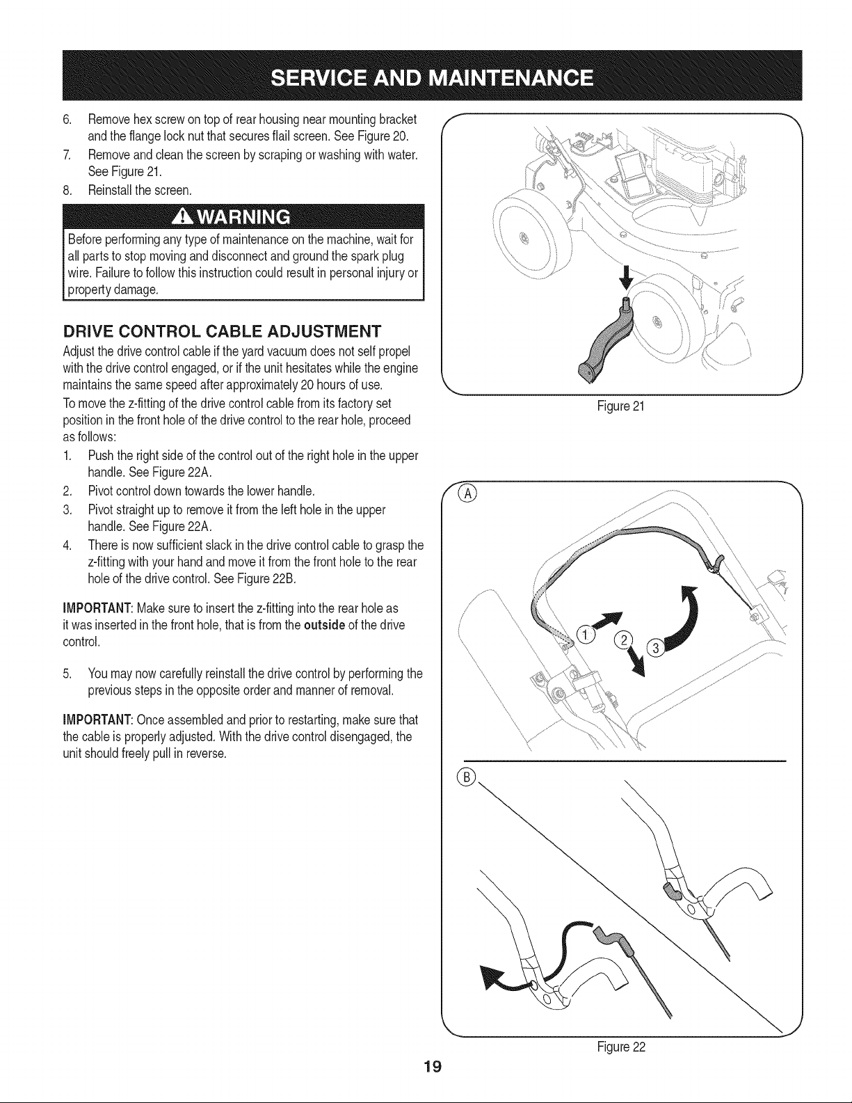
6. Removehexscrewon top of rear housingnear mountingbracket
andthe flangelocknutthatsecuresflail screen.SeeFigure20.
7. Removeand cleanthe screenby scrapingorwashingwithwater.
SeeFigure21.
8. Reinstallthe screen.
Beforeperforminganytype of maintenanceon the machine,waitfor
all partsto stopmovinganddisconnectandgroundthe sparkplug
wire. Failureto follow this instructioncould resultin personalinjuryor
propertydamage.
DRIVE CONTROL CABLE ADJUSTMENT
Adjustthe drivecontrolcableif theyard vacuumdoes not self propel
withthe drivecontrolengaged,orif the unithesitateswhilethe engine
maintainsthe same speedafterapproximately20 hoursof use.
Tomovethe z-fittingof the drivecontrolcablefromitsfactoryset
positioninthe frontholeof the drivecontrolto the rearhole,proceed
as follows:
1. Pushthe rightsideof thecontrol outof the rightholeinthe upper
handle.SeeFigure22A.
2. Pivotcontroldowntowardsthe lowerhandle.
3. Pivotstraightup to removeit fromthe leftholein the upper
handle.SeeFigure22A.
4. Thereis nowsufficientslackin the drivecontrolcableto graspthe
z-fittingwithyourhandandmoveit fromthe frontholeto the rear
holeof the drivecontrol.SeeFigure22B.
IMPORTANT:Makesureto insertthe z-fittingintothe rearholeas
it wasinsertedinthe fronthole,thatis fromthe outside of the drive
control.
5. Youmay nowcarefullyreinstallthe drivecontrolby performingthe
previoussteps in the oppositeorderandmannerof removal.
IMPORTANT:Onceassembledand priorto restarting,makesurethat
the cableis properlyadjusted.Withthe drivecontroldisengaged,the
unit shouldfreelypullin reverse.
f
\
J
Figure21
\
19
Figure22
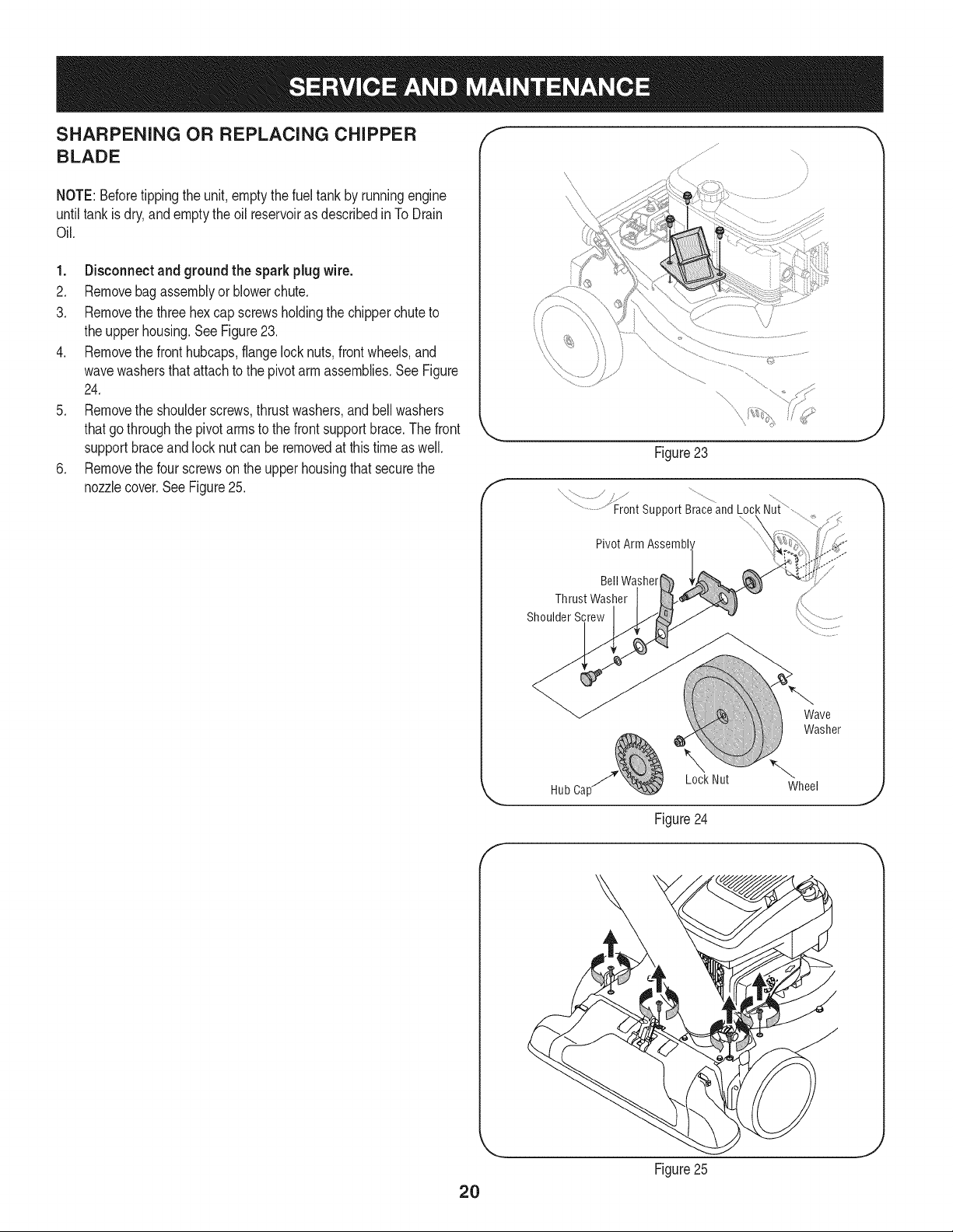
SHARPENING OR REPLACING CHIPPER
BLADE
NOTE:Beforetippingthe unit,emptythefuel tankby runningengine
untiltankisdry,andemptythe oil reservoiras describedinTo Drain
Oil.
1. Disconnectand groundthe sparkplugwire.
2. Removebagassemblyor blowerchute.
3. Removethe three hexcap screwsholdingthe chipperchuteto
the upperhousing.SeeFigure23.
4. Removethe fronthubcaps,flangelocknuts,frontwheels,and
wavewashersthatattachto the pivotarm assemblies.See Figure
24.
5. Removethe shoulderscrews,thrustwashers,and bell washers
thatgothroughthe pivotarmsto the frontsupportbrace.The front
supportbraceandlocknut can beremovedat this time as well.
6. Removethe four screwson the upperhousingthat securethe
nozzlecover.SeeFigure25.
f
Figure23
x /
..........................Front support Braceand Lock Nui,
Pivot Arm Assembl'
J
Bell Washer
Thrust Washer
Shoulder Screw
Wave
Washer
Lock Nut
Hub Ca[ Wheel
J
Figure24
f
2O
Figure25
J
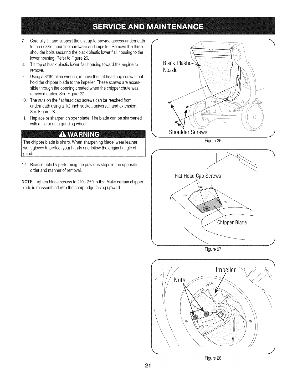
7. Carefullytilt andsupportthe unit upto provideaccessunderneath
to the nozzlemountinghardwareand impeller.Removethe three
shoulderboltssecuringthe black plasticlowerflail housingto the
lowerhousing.Referto Figure26.
8. Tilt top of black plasticlowerflail housingtowardthe engineto
remove.
9. Usinga 3/16"allenwrench,removetheflat headcap screwsthat
holdthe chipperbladeto the impeller.Thesescrewsare acces-
siblethroughtheopeningcreatedwhenthechipperchutewas
removedearlier.See Figure27.
10. Thenuts on the flat headcap screwscan be reachedfrom
underneathusinga 1/2-inchsocket,universal,and extension.
SeeFigure28.
11. Replaceor sharpenchipperblade.The bladecan be sharpened
witha fileor ona grindingwheel.
The chipperbladeis sharp.Whensharpeningblade,wear leather
workglovesto protectyourhandsandfollowthe originalangleof
grind.
12. Reassembleby performingthe previousstepsin theopposite
orderand mannerof removal.
NOTE:Tightenbladescrewsto 210- 250in-lbs.Makecertainchipper
bladeis reassembledwiththe sharpedgefacingupward.
Black
Nozzle
\
f
Shoulder Screws
Figure26
C
Flat Head Ca Screws
Chipper Blade
Figure27
J
Impeller
21
Figure28
J
Neverstoreyardvacuumwithfuel intankindoorsor inpoorly
ventilatedareaswherefuel fumesmayreachanopenflame,spark,
or pilotlight as ona furnace,waterheater,clothesdryer,or gas
appliance.
PREPARING THE ENGINE
Forenginesstoredover30 days:
1. To preventgumfromforminginfuel systemor oncarburetor
parts, runengineuntilit stopsfromlackof fuelor adda gasoline
additiveto the gas inthe tank. Ifyou usea gas additive,runthe
enginefor severalminutesto circulatethe additivethroughthe
carburetor--afterwhichthe engineandfuel can bestoredup to
six months.
2. Whileengineis still warm,changethe oil.
3. Removespark plugand pourapproximately1oz. (30rnl)of clean
engineoil intothe cylinder.Pullthe recoilstarterseveraltimesto
distributethe oil, andreinstallthe sparkplug.
4. Cleanengineof surfacedebris.
PREPARING THE YARD VACUUM
• Whenstoringthe yardvacuumin an unventilatedor metalstorage
shed,careshouldbetakento rustproofthe non-paintedsurfaces.
Usinga lightoil orsilicone,coatthe equipment,especiallyany
springs,bearings,and cables.
• Removealldirt fromexteriorof engineandequipment.
• Followlubricationrecommendations.
• Storeequipmentin a clean,dry area.Do not storein anarea
whereequipmentis presentthat may usea pilot lightor hasa
componentthatcan createa spark.
22
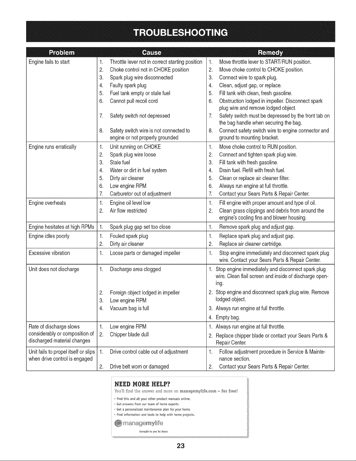
Enginefailsto start
Enginerunserratically
1. Throttlelevernot in correctstartingposition
2. Chokecontrolnot in CHOKEposition
3. Sparkplugwire disconnected
4. Faultysparkplug
5. Fueltank emptyor stale fuel
6. Cannotpull recoilcord
7. Safetyswitchnotdepressed
Engineoverheats
Enginehesitatesat high RPMs 1. Sparkpluggap settoo close
Engineidlespoorly 1. Fouledspark plug
2. Dirtyair cleaner
Excessivevibration 1. Loosepartsor damagedimpeller
Unitdoesnot discharge 1. Dischargeareaclogged
Rated dischargeslows
considerablyor compositionof
dischargedmaterialchanges
Unitfailsto propelitself orslips
whendrivecontrolisengaged
8. Safetyswitchwire is not connectedto
engineor notproperlygrounded
1. Unit runningon CHOKE
2. Sparkplugwire loose
3. Stalefuel
4. Wateror dirt in fuel system
5. Dirtyair cleaner
6. Lowengine RPM
7. Carburetorout of adjustment
1. Engineoil levellow
2. Air flow restricted
2. Foreignobject lodgedin impeller
3. Lowengine RPM
4. Vacuumbagis full
1. Lowengine RPM
2. Chipperbladedull
1. Drivecontrolcableout of adjustment
2. Drivebeltworn or damaged
1. Movethrottleleverto START/RUNposition.
2. Movechokecontrolto CHOKEposition.
3. Connectwire to sparkplug.
4. Clean,adjustgap,or replace.
5. Filltank with clean,fresh gasoline.
6. Obstructionlodgedin impeller.Disconnectspark
plugwire andremovelodgedobject.
7. Safetyswitch mustbe depressedby thefronttab on
the bag handlewhen securingthe bag.
8. Connectsafetyswitchwireto engineconnectorand
groundto mountingbracket.
1. Movechokecontrolto RUNposition.
2. Connectand tightenspark plugwire.
3. Filltank with fresh gasoline.
4. Drainfuel. Refillwithfreshfuel.
5. Cleanor replaceair cleanerfilter.
6. Alwaysrun engineat full throttle.
7. ContactyourSearsParts& RepairCenter.
1. Fillenginewith properamountandtype of oil.
2. Cleangrass clippingsand debrisfrom aroundthe
engine'scoolingfins and blowerhousing.
1. Removesparkplugandadjustgap.
1. Replacesparkplugandadjustgap.
2. Replaceair cleanercartridge.
1. Stopengineimmediatelyand disconnectsparkplug
wire.ContactyourSearsParts& RepairCenter.
1. Stopengineimmediatelyand disconnectsparkplug
wire.Cleanflail screenandinsideof dischargeopen-
ing.
2. Stopengineand disconnectsparkplugwire.Remove
lodgedobject.
3. Alwaysrun engineat full throttle.
4. Emptybag.
1. Alwaysrun engineat full throttle.
2. Replacechipperbladeor contactyourSearsParts&
RepairCenter.
1. Followadjustmentprocedurein Service& Mainte-
nancesection.
2. ContactyourSearsParts& RepairCenter.
Find this and all your other product manuals online.
Get answers from our team of home experts.
Get a personalized maintenance plan for your home.
Find information and tools to heLp with home projects.
23
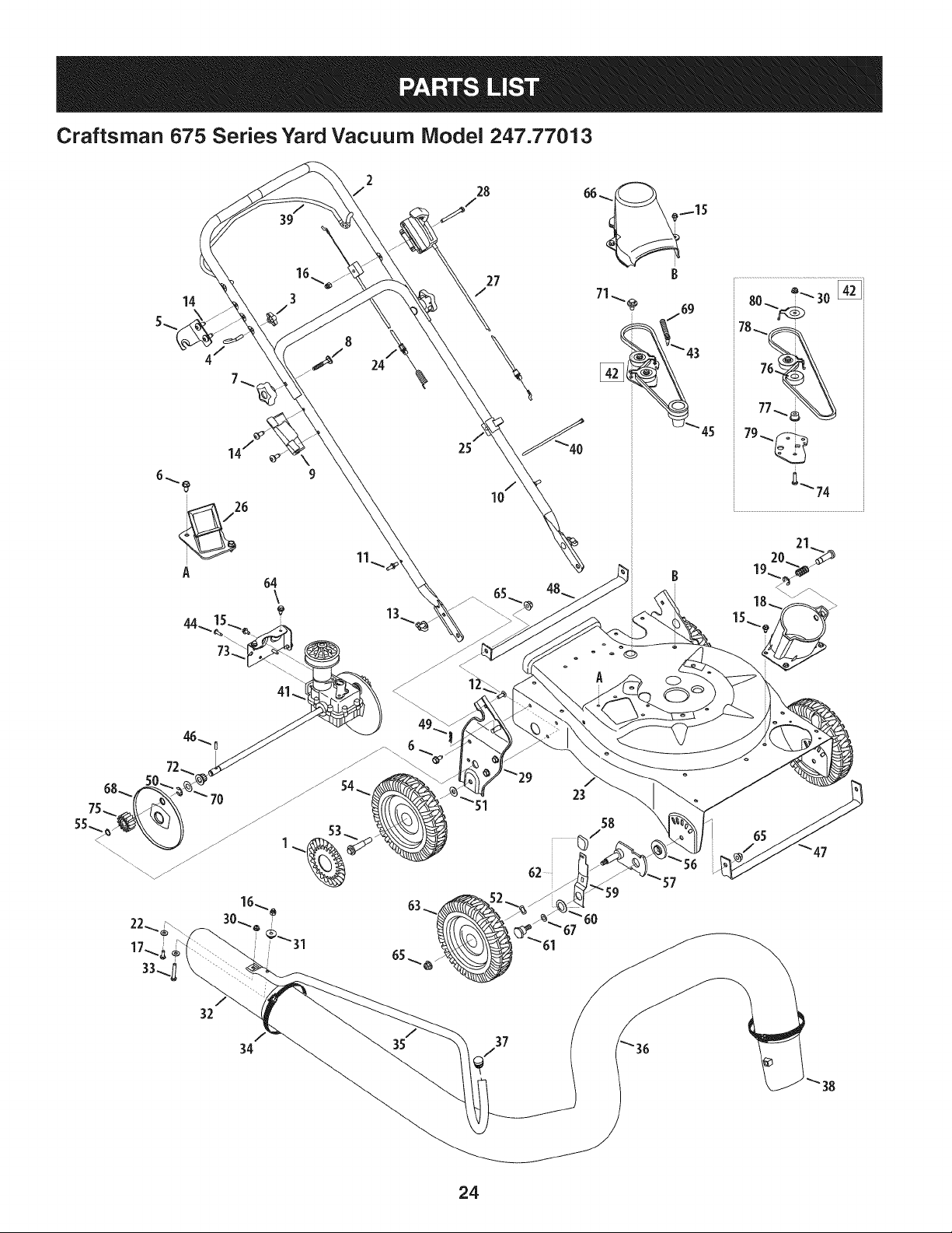
Craftsman 675 Series Yard Vacuum Model 247.77013
14
39
64
\
2
/
24
28
25
®
A
32
35
37
"67
_'61
59
_56
57
24
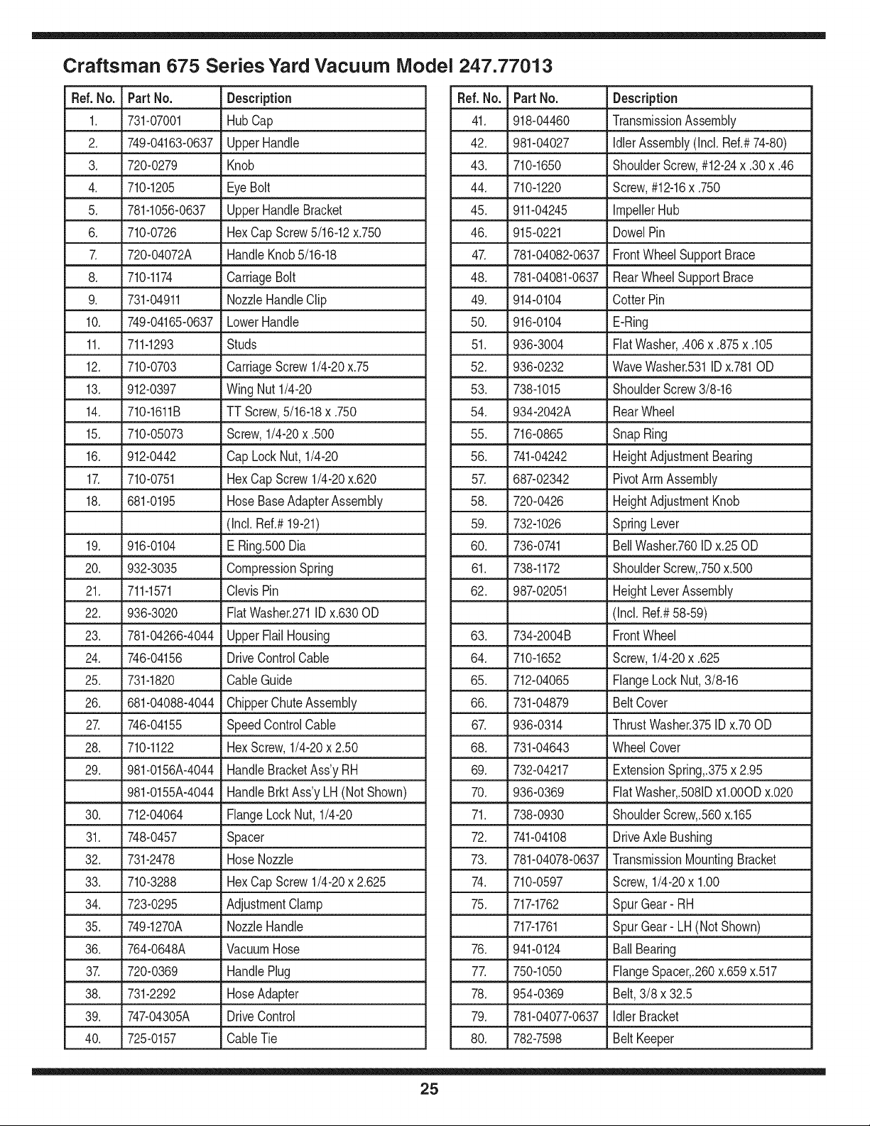
Craftsman 675 Series Yard Vacuum Model 247.77013
Ref. No. Part No. Description
1. 731-07001 HubCap
2. 749-04163-0637 UpperHandle
3. 720-0279 Knob
4. 710-1205 EyeBolt
5. 781-1056-0637 UpperHandleBracket
6. 710-0726 HexCap Screw5/16-12x.750
7. 720-04072A HandleKnob5/16-18
8. 710-1174 CarriageBolt
9. 731-04911 NozzleHandleClip
10. 749-04165-0637 LowerHandle
11. 711-1293 Studs
12. 710-0703 CarriageScrew1/4-20x.75
13. 912-0397 Wing Nut 1/4-20
14. 710-1611B TT Screw,5/16-18x .750
15. 710-05073 Screw,1/4-20x .500
16. 912-0442 Cap Lock Nut, 1/4-20
17. 710-0751 HexCap Screw1/4-20x.620
18. 681-0195 HoseBaseAdapterAssembly
(Incl. Ref.#19-21)
19. 916-0104 E Ring.500Dia
20. 932-3035 CompressionSpring
21. 711-1571 ClevisPin
22. 936-3020 FiatWasher.271IDx.630 OD
23. 781-04266-4044 UpperFlailHousing
24. 746-04156 DriveControlCable
25. 731-1820 CableGuide
26. 681-04088-4044 ChipperChuteAssembly
27. 746-04155 Speed ControlCable
28. 710-1122 HexScrew,1/4-20x 2.50
29. 981-0156A-4044 HandleBracketAss'yRH
981-0155A-4044 HandleBrktAss'yLH (Not Shown)
30. 712-04064 FlangeLockNut, 1/4-20
31. 748-0457 Spacer
32. 731-2478 HoseNozzle
33. 710-3288 HexCap Screw1/4-20x 2.625
34. 723-0295 AdjustmentClamp
35. 749-1270A NozzleHandle
36. 764-0648A VacuumHose
37. 720-0369 HandlePlug
38. 731-2292 HoseAdapter
39. 747-04305A DriveControl
40. 725-0157 CableTie
Ref.No. Part No. Description
41. 918-04460 TransmissionAssembly
42. 981-04027 IdlerAssembly(Incl. Ref.#74-80)
43. 710-1650 ShoulderScrew,#12-24x .30x .46
44. 710-1220 Screw,#12-16x .750
45. 911-04245 ImpellerHub
46. 915-0221 DowelPin
47. 781-04082-0637 FrontWheelSupportBrace
48. 781-04081-0637 RearWheelSupportBrace
49. 914-0104 CotterPin
50. 916-0104 E-Ring
51. 936-3004 FiatWasher,.406x .875x .105
52. 936-0232 WaveWasher.531IDx.781OD
53. 738-1015 ShoulderScrew3/8-16
54. 934-2042A RearWheel
55. 716-0865 SnapRing
56. 741-04242 HeightAdjustmentBearing
57. 687-02342 PivotArmAssembly
58. 720-0426 HeightAdjustmentKnob
59. 732-1026 SpringLever
60. 736-0741 BellWasher.760IDx.25OD
61. 738-1172 ShoulderScrew,.750x.500
62. 987-02051 HeightLeverAssembly
(Incl. Ref.#58-59)
63. 734-2004B FrontWheel
64. 710-1652 Screw,1/4-20x .625
65. 712-04065 FlangeLockNut,3/8-16
66. 731-04879 BeltCover
67. 936-0314 ThrustWasher.375ID x.70OD
68. 731-04643 WheelCover
69. 732-04217 ExtensionSpring,.375x 2.95
70. 936-0369 FiatWasher,.5081Dxl.0OODx.020
71. 738-0930 ShoulderScrew,.560x.165
72. 741-04108 DriveAxle Bushing
73. 781-04078-0637 TransmissionMountingBracket
74. 710-0597 Screw,1/4-20x 1.00
75. 717-1762 SpurGear- RH
717-1761 SpurGear- LH (NotShown)
76. 941-0124 BallBearing
77. 750-1050 FlangeSpacer,.260x.659x.517
78. 954-0369 Belt,3/8 x 32.5
79. 781-04077-0637 Idler Bracket
80. 782-7598 Belt Keeper
25
Craftsman 675 Series Yard Vacuum Model 247.77013
27 /
49
@/
45
28/
2
o
48
A
21.. i
22 24
16
25
26
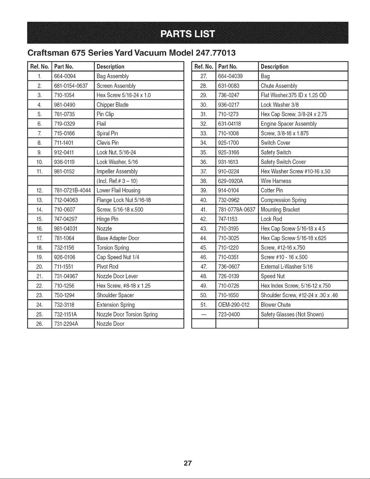
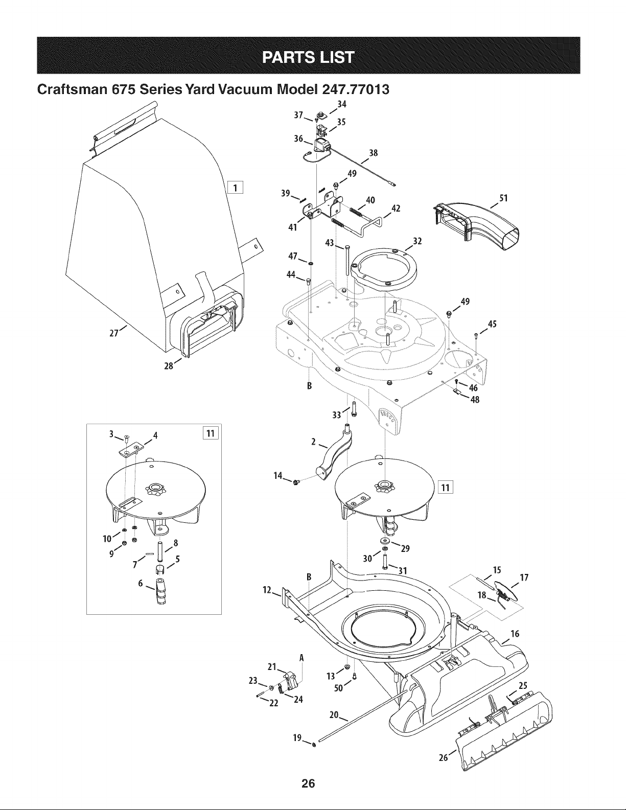
Craftsman 675 Series Yard Vacuum iVlodel 247.77013
Ref. No. Part No. Description
1. 664-0094 BagAssembly
2. 681-0154-0637 ScreenAssembly
3. 710-1054 HexScrew5/16-24x 1.0
4. 981-0490 ChipperBlade
5. 781-0735 PinClip
6. 719-0329 Flail
7. 715-0166 SpiralPin
8. 711-1401 ClevisPin
9. 912-0411 Lock Nut,5/16-24
10. 936-0119 LockWasher,5/16
11. 981-0152 ImpellerAssembly
(Incl.Ref.#3 - 10)
12. 781-0721B-4044 LowerFlailHousing
13. 712-04063 FlangeLockNut5/16-18
14. 710-0607 Screw,5/16-18x.500
15. 747-04297 HingePin
16. 981-04031 Nozzle
17. 781-1064 BaseAdapterDoor
18. 732-1156 TorsionSpring
19. 926-0106 CapSpeed Nut 1/4
20. 711-1551 PivotRod
21. 731-04967 NozzleDoor Lever
22. 710-1256 HexScrew,#8-18x 1.25
23. 750-1294 ShoulderSpacer
24. 732-3118 ExtensionSpring
25. 732-1151A NozzleDoorTorsionSpring
26. 731-2294A NozzleDoor
Ref.No. Part No. Description
27. 664-04039 Bag
28. 631-0083 ChuteAssembly
29. 736-0247 FiatWasher.375ID x 1.25OD
30. 936-0217 LockWasher3/8
31. 710-1273 HexCap Screw,3/8-24 x 2.75
32. 631-04118 EngineSpacerAssembly
33. 710-1008 Screw,3/8-16x 1.875
34. 925-1700 SwitchCover
35. 925-3166 SafetySwitch
36. 931-1613 SafetySwitchCover
37. 910-0224 HexWasherScrew#10-16x.50
38. 629-0920A Wire Harness
39. 914-0104 CotterPin
40. 732-0962 CompressionSpring
41. 781-0778A-0637 MountingBracket
42. 747-1153 LockRod
43. 710-3195 HexCap Screw5/16-18x 4.5
44. 710-3025 HexCap Screw5/16-18x.625
45. 710-1220 Screw,#12-16x.750
46. 710-0351 Screw#10- 16x.500
47. 736-0607 ExternalbWasher 5/16
48. 726-0139 SpeedNut
49. 710-0726 Hex indexScrew,5/16-12x.750
50. 710-1650 ShoulderScrew,#12-24x .30x .46
51. 0EM-290-012 BlowerChute
-- 723-0400 SafetyGlasses(NotShown)
27
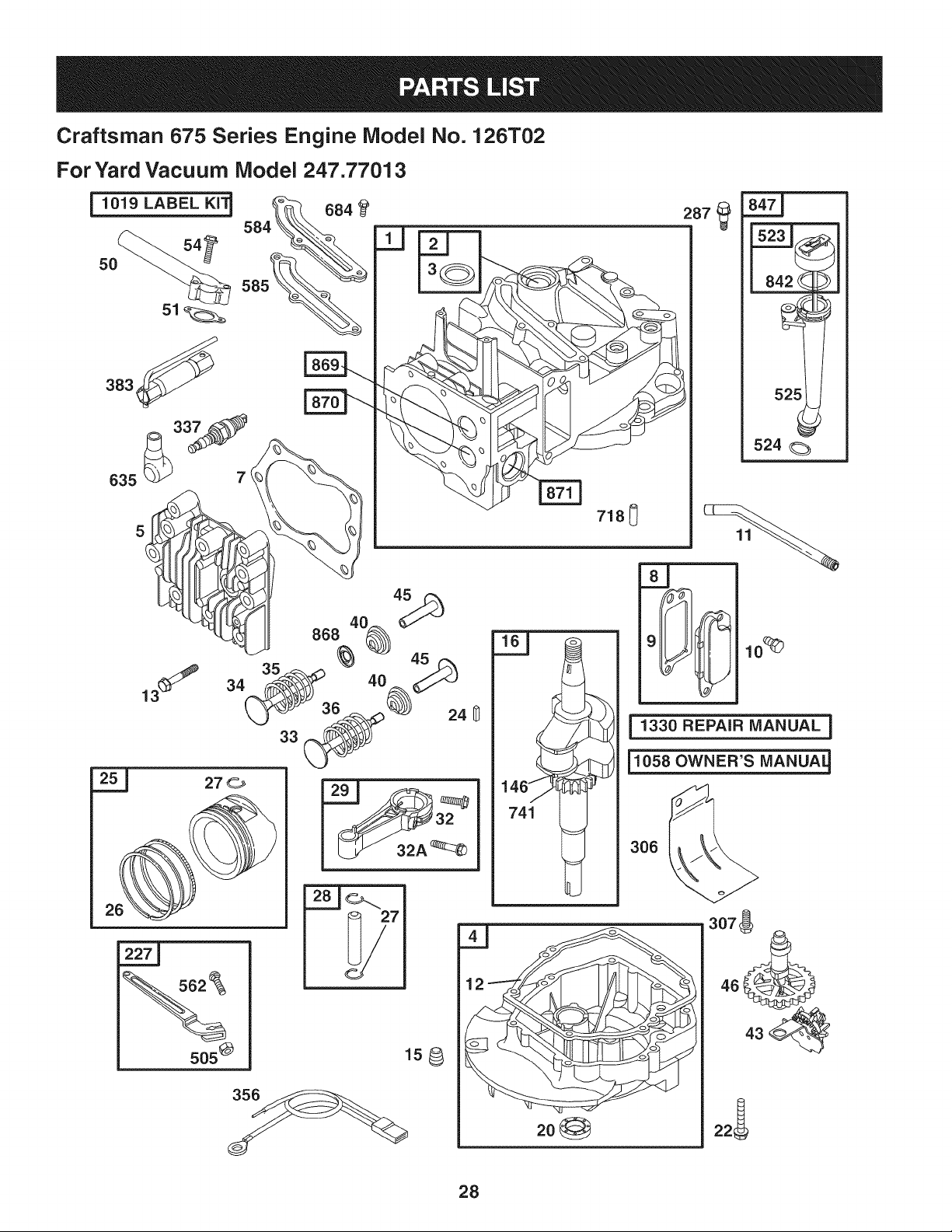
Craftsman 675 Series Engine Model No. 126T02
ForYard Vacuum Model 247.77013
j1019 LABEL KI'_
5O
383_'_
7(
635
287
718_
1330 REPAIR MANUAL ]
i1058 OWNER'S MANUA_
306
505 @
28
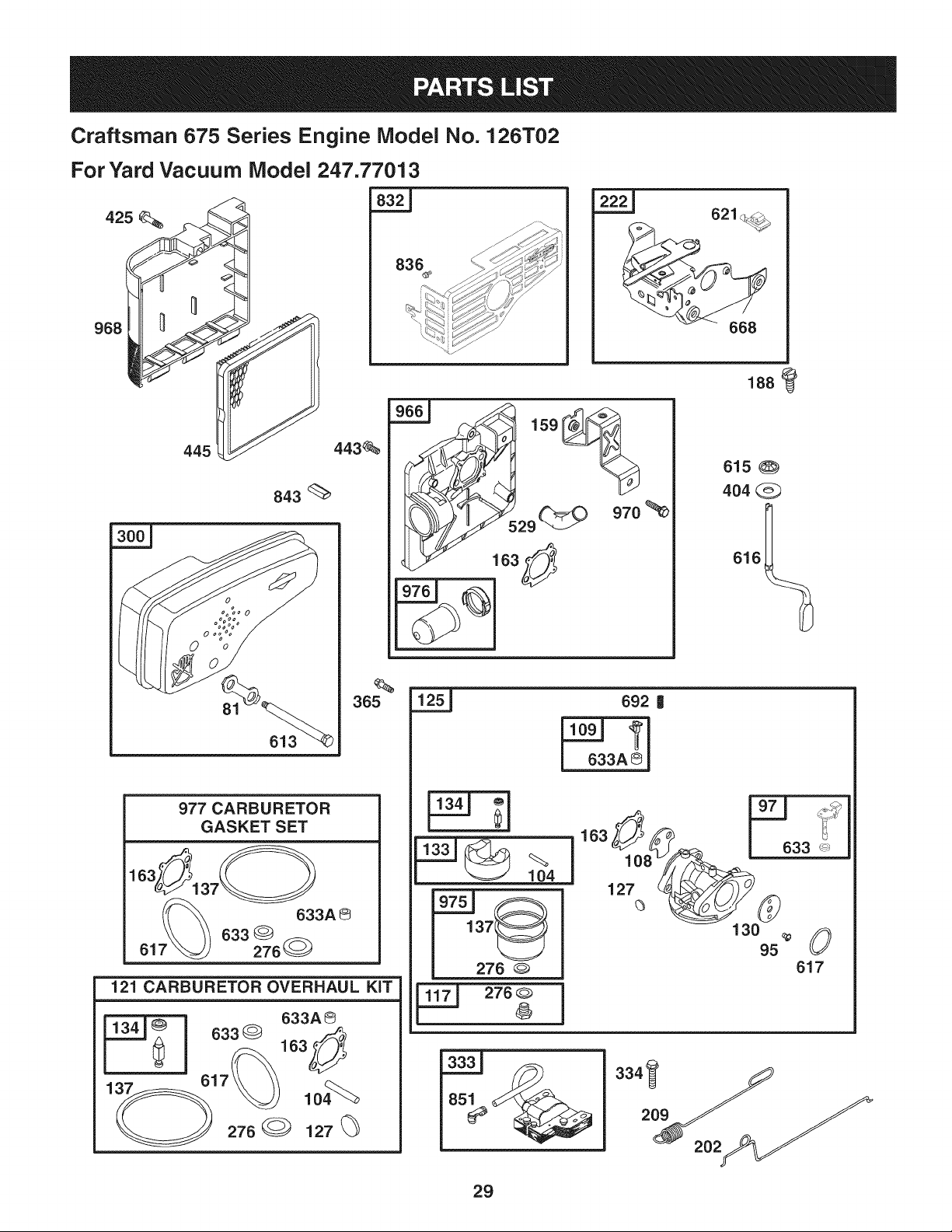
Craftsman 675 Series Engine Model No. 126T02
For Yard Vacuum Model 247.77013
425
445
443_
843
81
613
977 CARBURETOR
GASKET SET
163_137_
7_ 633A @
633G
61 276_
365
121 CARBURETOR OVERHAUL KiT
633A@
163_
lo4%_
276 127
968
836 _ _;_ _._/
621_
966_ 159
._ 29_
970
615
404
616__
633_
692 |
633A @
104
137(
276
276
163 _
127<3
130
95
633
0
617
29
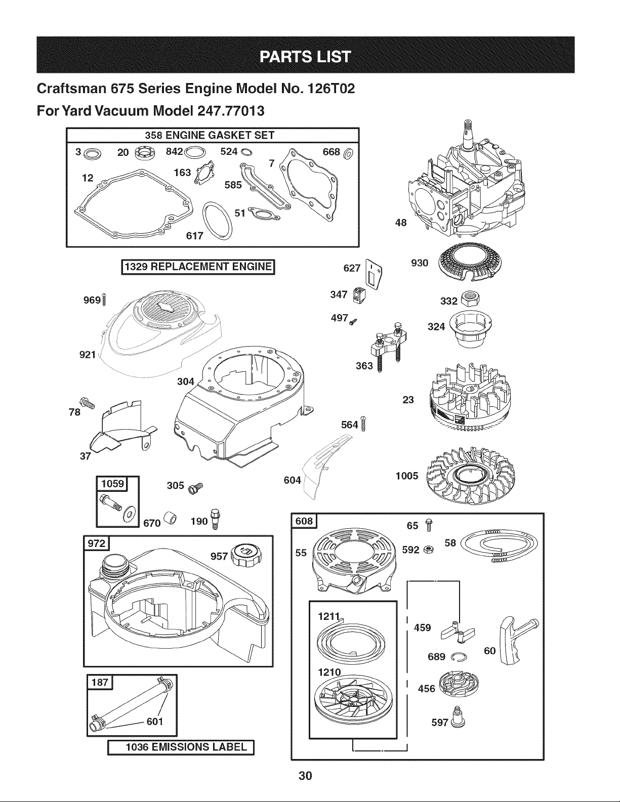
Craftsman 675 Series Engine Model No. 126T02
ForYard Vacuum Model 247.77013
3_ 20
358 ENGINE GASKET SET
__329 REPLACEMENT ENGINE 1
921 '_\
%
78
930
I
601
1036 EMiSSiONS LABEL I
!
1005
m
45o
60
689 O
3O
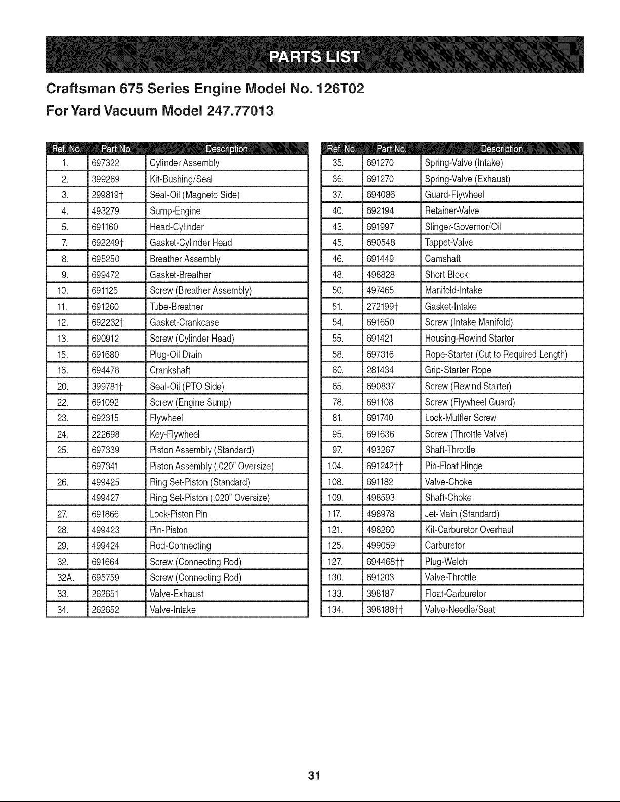
Craftsman 675 Series Engine Model No. 126T02
For Yard Vacuum iVlodel 247.77013
D = " O
697322 CylinderAssembly
2. 399269 Kit-Bushing/Seal
3. 299819t Seal-Oil(MagnetoSide)
4. 493279 Sump-Engine
5. 691160 Head-Cylinder
7. 692249t Gasket-CylinderHead
8. 695250 BreatherAssembly
9. 699472 Gasket-Breather
10. 691125 Screw(BreatherAssembly)
11. 691260 Tube-Breather
12. 692232t Gasket-Crankcase
13. 690912 Screw(CylinderHead)
15. 691680 Plug-OilDrain
16. 694478 Crankshaft
20. 399781t Seal-Oil(PTOSide)
22. 691092 Screw(EngineSump)
23. 692315 Flywheel
24. 222698 Key-Flywheel
25. 697339 PistonAssembly(Standard)
697341 PistonAssembly(.020"Oversize)
26. 499425 RingSet-Piston(Standard)
499427 RingSet-Piston(.020"Oversize)
27. 691866 Lock-PistonPin
28. 499423 Pin-Piston
29. 499424 Rod-Connecting
32. 691664 Screw(ConnectingRod)
32A. 695759 Screw(ConnectingRod)
33. 262651 Valve-Exhaust
34. 262652 Valve-Intake
D = O Q
691270 Spring-Valve(Intake)
36. 691270 Spring-Valve(Exhaust)
37. 694086 Guard-Flywheel
40. 692194 Retainer-Valve
43. 691997 Slinger-Governor/Oil
45. 690548 Tappet-Valve
46. 691449 Camshaft
48. 498828 Short Block
50. 497465 Manifold-Intake
51. 272199t Gasket-Intake
54. 691650 Screw(IntakeManifold)
55. 691421 Housing-RewindStarter
58. 697316 Rope-Starter(Cutto RequiredLength)
60. 281434 Grip-StarterRope
65. 690837 Screw(RewindStarter)
78. 691108 Screw(FlywheelGuard)
81. 691740 Lock-MufflerScrew
95. 691636 Screw(ThrottleValve)
97. 493267 Shaft-Throttle
104. 691242tt Pin-FloatHinge
108. 691182 Valve-Choke
109. 498593 Shaft-Choke
117. 498978 Jet-Main(Standard)
121. 498260 Kit-CarburetorOverhaul
125. 499059 Carburetor
127. 694468tt Plug-Welch
130. 691203 Valve-Throttle
133. 398187 Float-Carburetor
134. 398188tt Valve-Needle/Seat
31
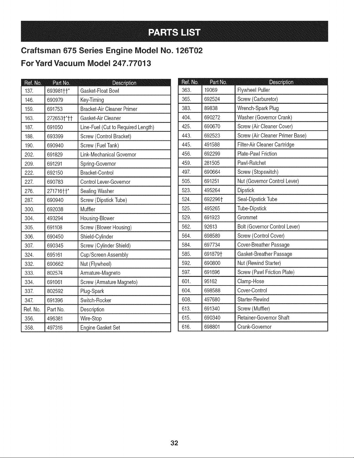
Craftsman 675 Series Engine Model No. 126T02
ForYard Vacuum Model 247.77013
D = O
693981tt* Gasket-FloatBowl
146. 690979 Key-Timing
159. 691753 Bracket-AirCleanerPrimer
163. 272653t*tt Gasket-AirCleaner
187. 691050 Line-Fuel(Cutto RequiredLength)
188. 693399 Screw(ControlBracket)
190. 690940 Screw(FuelTank)
202. 691829 Link-MechanicalGovernor
209. 691291 Spring-Governor
222. 692150 Bracket-Control
227. 690783 ControlLever-Governor
276. 271716tt* SealingWasher
287. 690940 Screw(DipstickTube)
300. 692038 Muffler
304. 493294 Housing-Blower
305. 691108 Screw(BlowerHousing)
306. 690450 Shield-Cylinder
307. 690345 Screw(CylinderShield)
324. 695161 Cup/ScreenAssembly
332. 690662 Nut(Flywheel)
333. 802574 Armature-Magneto
334. 691061 Screw(ArmatureMagneto)
337. 802592 Plug-Spark
347. 691396 Switch-Rocker
Ref.No. PartNo. Description
356. 496381 Wire-Stop
358. 497316 EngineGasketSet
D = O
19069 FlywheelPuller
365. 692524 Screw(Carburetor)
383. 89838 Wrench-SparkPlug
404. 690272 Washer(GovernorCrank)
425. 690670 Screw(AirCleanerCover)
443. 692523 Screw(AirCleanerPrimerBase)
445. 491588 Filter-AirCleanerCartridge
456. 692299 Plate-PawlFriction
459. 281505 PawI-Ratchet
497. 690664 Screw(Stopswitch)
505. 691251 Nut(GovernorControlLever)
523. 495264 Dipstick
524. 692296t Seal-DipstickTube
525. 495265 Tube-Dipstick
529. 691923 Grommet
562. 92613 Bolt(GovernorControl Lever)
564. 698589 Screw(ControlCover)
584. 697734 Cover-BreatherPassage
585. 691879t Gasket-BreatherPassage
592. 690800 Nut(RewindStarter)
597. 691696 Screw(Pawl FrictionPlate)
601. 95162 Clamp-Hose
604. 698588 Cover-Control
608. 497680 Starter-Rewind
613. 691340 Screw(Muffler)
615. 690340 Retainer-GovernorShaft
616. 698801 Crank-Governor
32
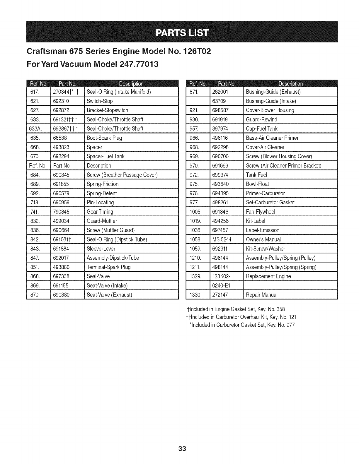
Craftsman 675 Series Engine Model No. 126T02
For Yard Vacuum iVlodel 247.77013
270344t*tt
621. 692310
62Z 692872
633. 691321ff*
633A. 693867ff*
D = I! It
Seal-ORing(IntakeManifold)
Switch-Stop
Bracket-Stopswitch
Seal-Choke/ThrottleShaft
Seal-Choke/ThrottleShaft
635. 66538 Boot-Spark Plug
668. 493823 Spacer
670. 692294 SpacepFueITank
Ref.No. PartNo. Description
684. 690345 Screw(BreatherPassageCover)
689. 691855 Spring-Friction
692. 690579 Spring-Detent
718. 690959 Pin-Locating
741. 790345 Gear-Timing
832. 499034 Guard-Muffler
836. 690664 Screw(MufflerGuard)
842. 6910311- Seal-ORing(DipstickTube)
843. 691884 Sleeve-Lever
847. 692017 Assembly-Dipstick/Tube
851. 493880 Terminal-SparkPlug
868. 697338 Seal-Valve
869. 691155 Seat-Valve(intake)
870. 690380 Seat-Valve(Exhaust)
m = I! O
262001 Bushing-Guide(Exhaust)
63709 Bushing-Guide(Intake)
921. 698587 Cover-BlowerHousing
930. 691919 Guard-Rewind
957. 397974 Cap-FuelTank
966. 496116 Base-AirCleanerPrimer
968. 692298 Cover-AirCleaner
969. 690700 Screw(BlowerHousingCover)
970. 691669 Screw(Air CleanerPrimerBracket)
972. 699374 Tank-Fuel
975. 493640 Bowl-Float
976. 694395 Primer-Carburetor
977. 498261 Set-CarburetorGasket
1005. 691346 Fan-Flywheel
1019. 494256 Kit-Label
1036. 697457 Label-Emission
1058. MS5244 Owner'sManual
1059. 692311 Kit-Screw/Washer
1210. 498144 Assembly-Pulley/Spring(Pulley)
1211. 498144 Assembly-Pulley/Spring(Spring)
1329. 123K02- ReplacementEngine
0240-E1
1330. 272147 RepairManual
tlncluded in EngineGasketSet,Key.No.358
ttlncluded in CarburetorOverhaulKit, Key.No.121
*includedin CarburetorGasketSet,Key.No.977
33
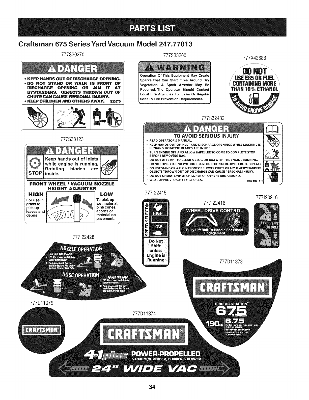
Craftsman 675 Series Yard Vacuum Model 247.77013
777S30270 777S33200
= KEEP HANDS OUT OF D|SCHARGE OPEN|NO=
= DO NOT STAND OR WALK iN FRONT OF
DISCHARGE OPENING OR AiM iT AT
BYSTANDERS= OBJECTS THROWN OUT OF
CHUTE CAN CAUSE PERSONAL iNJURY=
• KEEP CHILDREN AND OTHERS AWAY= $30270
777S33123
Keep hands out of inlets
while engine is running,
Rotating blades are
inside.
FRONT WHEEL / VACUUM NOZZLE
HEIGHT ADJUSTER
LOW
To pick up
wet material,
pine cones,
acorns or
I materiaJ on
J pavement,
777122428
I Operation Of This Equipment May Create
Sparks That Can Start Fires Around Dry
Vegetation, A Spark Arrestor May Be
Required. The Operator Should Contact
Local Fire Agencies For Laws Or Regula=
t_ion Requ'_ements.
777S32432
777X43688
..................DO ............................
USEE85 ORFUEL..............
CONTAiNiNGMORE
THAN10% ETHAHOL
TO AVOID SERIOUS iNJURY
• READ OPERATOR'S MANUAL.
• KEEP HANDS OUT OF iNLET AND DISCHARGE OPENINGS WHILE MACHINE iS
RUNNING. ROTATING BLADES ARE iNSiDE.
• TURN ENGINE OFF AND ALLOW iMPELLER TO COME TO COMPLETE STOP
BEFORE REMOVING BAG.
• DO NOT ATTEMPT TO CLEAR A CLOG OR JAM WiTH THE ENGINE RUNNING.
" DO NOT OPERATE UNiTWiTHOUT BAG OR OPTIONAL BLOWER CHUTE iN PLACE.
• DO NOT STAND OR WALK IN FRONT OF BLOWER CHUTE OR AiM iT AT BYSTANDERS.
OBJECTS THROWN OUT OF DISCHARGE CAN CAUSE PERSONAL iNJURY.
• DO NOT OPERATE WHEN CHILDREN OR OTHERS ARE AROUND.
• WEAR APPROVED SAFETY GLASSES.
$32432 AC
777i22415
777122416
777Dl1373
777120916
777Dl1379
777Dl1374
34

35
(Thispageapplicableinthe U.S.A.and Canadaonly.)
Sears Brands Management Corporation (Sears), the California Air Resources Board (CARD)
and the United States Environmental Protection Agency (U.S. EPA)
Emission Control System Warranty Statement (Owner's Defect Warranty Rights and Obligations)
EMISSIONCONTROLWARRANTYCOVERAGEISAPPLICABLETOCERTI-
FIEDENGINESPURCHASEDIN CALIFORNIAIN 1995ANDTHEREAF-
TER,WHICHARE USED INCALIFORNIA,ANDTOCERTIFIEDMODEL
California and United States Emission
The CaliforniaAir ResourcesBoard(CARD),U.S.EPAand Searsare pleased
to explainthe EmissionControlSystemWarrantyon your modelyear2000and
latersmalloff-roadengine(SORE).InCalifornia,newsmall off-roadengines
mustbe designed,builtand equippedto meetthe State'sstringentanti-smog
standards.Elsewherein theUnitedStates, newnon-road,spark-ignition
enginescertifiedfor modelyear 1997and latermustmeetsimilarstandardsset
forth bythe U.S.EPA.Sears mustwarranttheemissioncontrolsystemon your
YEAR 1997AND LATERENGINESWHICHARE PURCHASEDAND USED
ELSEWHEREIN THE UNITEDSTATES(ANDAFTERJANUARY1,2001 IN
CANADA).
Control Defects Warranty Statement
enginefor the periodsoftime listedbelow,providedthere has been noabuse,
neglector impropermaintenanceof your smalloff-roadengine.Youremis-
sion controlsystemincludespartssuchas thecarburetor,air cleaner,ignition
system,mufflerand catalyticconverter.Also includedmaybe connectorsand
otheremissionrelatedassemblies.Wherea warrantableconditionexists,Sears
will repairyour smalloff-roadengineat no costto you includingdiagnosis,parts
and labor.
Sears Emission Control Defects Warranty Coverage
Smalloff-roadenginesarewarrantedrelativeto emissioncontrolpartsdefects
fora period of one year,subjectto provisionsset forthbelow.Ifanycovered
Owner's Warranty
Asthe smalloff-roadengine owner,you are responsiblefor theperformanceof
therequiredmaintenancelistedin yourOperatingand MaintenanceInstruc-
tions.Searsrecommendsthatyouretainallyourreceiptscoveringmaintenance
on yoursmalloff-roadengine,butSears cannotdenywarrantysolelyfor the
lackof receiptsorfor yourfailureto ensurethe performanceof all scheduled
maintenance.As the smalloff-roadengineowner,youshouldhoweverbe
awarethat Searsmaydenyyou warrantycoverageif your smalloff-roadengine
ora part hasfaileddueto abuse,neglect,impropermaintenanceor unap-
parton yourengineis defective,the part will be repairedorreplacedbySears.
Responsibilities
provedmodifications.Youare responsiblefor presentingyour smalloff-road
engineto an AuthorizedSearsServiceDealeras soonas a problemexists.The
undisputedwarrantyrepairsshouldbe completedina reasonableamountof
time,not to exceed30days.Ifyou haveany questionsregardingyourwarranty
rightsand responsibilities,you shouldcontacta SearsService Representative
at 1-800-469-4663.The emissionwarrantyis a defectswarranty.Defectsare
judgedon normalengineperformance.The warrantyis notrelatedto an in-use
emissiontest.
Sears Emission Control Defects Warranty Provisions
ThefollowingarespecificprovisionsrelativetoyourEmissionControlDefectsWarrantyCoverage.Itisin additiontotheSearsenginewarrantyfornon-regulated
enginesfound in theOperatingand MaintenanceInstructions.
1. WarrantedParts
Coverageunderthis warrantyextendsonly to the parts listedbelow(the
emissioncontrolsystemsparts)to the extentthese partswere presenton
theenginepurchased.
a. FuelMeteringSystem
• Cold start enrichmentsystem
• Carburetorand internalparts
• FuelPump
b. Air lnduction System
• Air cleaner
• Intakemanifold
c. IgnitionSystem
• Spark plug(s)
• Magnetoignitionsystem
d. CatalystSystem
• Catalyticconverter
• Exhaustmanifold
• Air injectionsystemor pulsevalve
e. MiscellaneousItemsUsedin AboveSystems
• Vacuum,temperature,position,timesensitivevalves
andswitches
• Connectorsandassemblies
2. Lengthof Coverage
Searswarrantsto the initialownerand eachsubsequentpurchaserthat
theWarrantedPartsshallbe free from defects in materialsandworkman-
shipwhich causedthefailure of the WarrantedPartsfor a periodof one
yearfromthe datethe engineis deliveredto a retailpurchaser.
3. NoCharge
Repairor replacementof anyWarrantedPartwill be performedat no
chargeto the owner,includingdiagnosticlabor whichleads to the
determinationthata WarrantedPartis defective,if the diagnosticworkis
performedat anAuthorizedSears ServiceDealer.Foremissionswarranty
servicecontact yournearestAuthorizedSears ServiceDealeras listed in
the "YellowPages"under"Engines,Gasoline,""GasolineEngines,""Lawn
Mowers,"orsimilarcategory.
4. Claimsand CoverageExclusions
Warrantyclaimsshall be filed in accordancewiththe provisionsof the
Sears EngineWarrantyPolicy.Warrantycoverageshall be excludedfor
failuresof WarrantedPartswhichare notoriginal Sears partsor because
of abuse,neglector impropermaintenanceas setforth inthe Sears
EngineWarrantyPolicy.Sears is notliableto coverfailuresof Warranted
Partscausedby theuse of add-on, non-original,or modifiedparts.
5. Maintenance
Any WarrantedPart whichis notscheduledfor replacementas required
maintenanceor whichis scheduledonly for regularinspectionto the effect
of "repairor replaceas necessary"shallbe warrantedas to defectsfor the
warrantyperiod.Any WarrantedPartwhich is scheduledfor replacement
as requiredmaintenanceshallbe warrantedas to defectsonly forthe
periodof time upto the firstscheduledreplacementfor that part. Any
replacementpart that is equivalentin performanceand durabilitymay
be usedin the performanceof any maintenanceor repairs.The owneris
responsibleforthe performanceof all requiredmaintenance,as definedin
the SearsOperatingand MaintenanceInstructions.
6. ConsequentialCoverage
Coveragehereundershallextendto the failure of any enginecomponents
caused bythe failureof any WarrantedPartstill underwarranty.
Inthe USAandCanada,a 24 hourhotline, 1-800-469-4663,has a menu of pre-recordedmessagesofferingyou enginemaintenanceinformation.
GDOC-100188Rev.B
36
Look For Relevant Emissions Durability Period and
Air index information On Your Engine Emissions Label
Engines that are certified to meet the California Air Resources Board (CARB) Tier 2 Emission Standards must
display information regarding the Emissions Durability Period and the Air Index. Sears Brands Management
Corporation makes this information available to the consumer on our emission labels.
The Emissions Durability Period describes the number of hours of actual running time for which the engine is
certified to be emissions compliant, assuming proper maintenance in accordance with the Operating & Mainte-
nance Instructions. The following categories are used:
Moderate: Engine is certified to be emission compliant for 125 hours of actual engine running time.
Intermediate: Engine is certified to be emission compliant for 250 hours of actual engine running time.
Extended: Engine is certified to be emission compliant for 500 hours of actual engine running time.
For example, a typical walk-behind lawn mower is used 20 to 25 hours per year. Therefore, the Emissions
Durability Period of an engine with an intermediate rating would equate to 10 to 12 years.
The Air index is a calculated number describing the relative level of emissions for a specific engine family. The
lower the Air Index, the cleaner the engine. This information is displayed in graphical form on the emissions label.
After July 1,2000, Look For Emissions Compliance Period
On Engine Emissions Compliance Label
After July 1, 2000 certain Sears Brands Management Corporation engines will be certified to meet the United
States Environmental Protection Agency (USEPA) Phase 2 emission standards. For Phase 2 certified engines, the
Emissions Compliance Period referred to on the Emissions Compliance label indicates the number of operating
hours for which the engine has been shown to meet Federal emission requirements.
For engines less than 225 cc displacement, Category C = 125 hours, B = 250 hours and A = 500 hours.
For engines of 225 cc or more, Category C = 250 hours, B = 500 hours and A = 1000 hours.
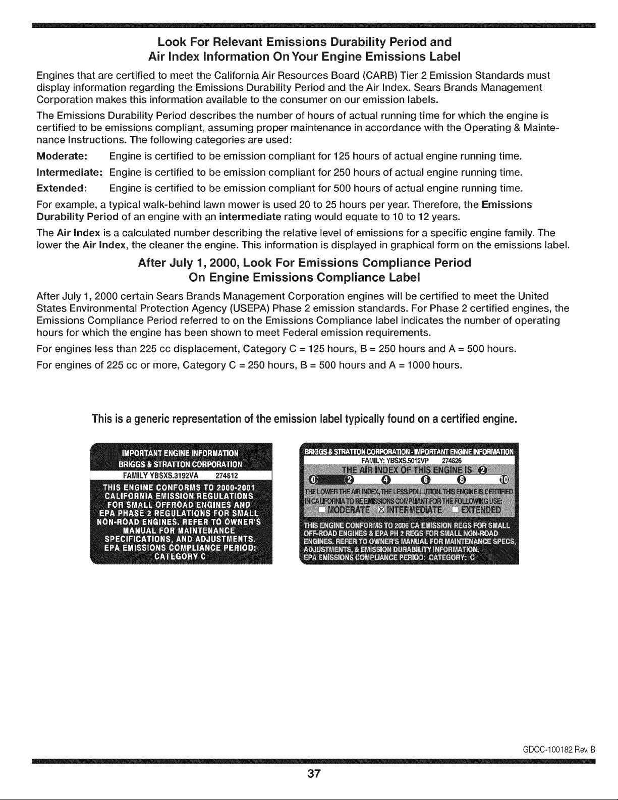
This is a generic representation of the emission label typically found on a certified engine.
FAMILYYBSXS.3192VA 274812
GDOC-100182Rev.B
37
Congratulations on making a smart purchase. Your new Craftsman® product is designed and
manufactured for years of dependable operation. But like all products, it may require repair
from time to time. That's when having a Repair Protection Agreement can save you money and
aggravation.
Here's what the Repair Protection Agreement* includes:
[] Expert service by our 10,000 professional repair specialists
[] Unlimited service and no charge for parts and labor on all covered repairs
[] Product replacement up to $1500 if your covered product can't be fixed
[] Discount of 25% from regular price of service and related installed parts not covered by the
agreement; also, 25% off regular price of preventive maintenance check
[] Fast help by phone - we call it Rapid Resolution - phone support from a Sears representative.
Think of us as a "talking owner's manual."
Once you purchase the Repair Protection Agreement, a simple phone call is all that it takes for you
to schedule service. You can call anytime day or night, or schedule a service appointment online.
The Repair Protection Agreement is a risk-free purchase. If you cancel for any reason during the
product warranty period, we will provide a full refund. Or, a prorated refund anytime after the
product warranty period expires. Purchase your Repair Protection Agreement today!
Some limitations and exclusions apply. For prices and additional information in the U.S.A.
call 1=800=827=6655.
*Coverage in Canada varies on some items. For full details call Sears Canada at 1=800=361=
6665.
Sears Installation Service
For Sears professional installation of home appliances, garage door openers, water heaters, and
other major home items, in the U.S.A. or Canada call 1=800=4=MY=HOME®.
38
Declaraci6n de garantia ....................... Pagina 39
Practicas operacion seguras ............... Pagina 40
Montaje ................................................ Pagina 44
Operacion ............................................ Pagina 48
Servicio y Mantenimiento .................... Pagina 52
Almacenamiento fuera de temporada .... Pagina 58
Solucion de problemas ...................... Pagina 59
Etiquetas de seguridad ....................... Pagina 7
Lista de piezas ........................................ Pagina 24
Acuerdo de Proteccion Para
Reparaciones ....................................... Pagina 63
NOmero de servicio ..................... Cubierta posterior
ARTESANO DE DOSANOS DE GARANTJA
PORDOSANOS(S)apartirdelafechadecompra,esteproductoest&garantizadocontracualquierdefectode materialo manode obra.Un
productodefectuosorecibir&la reparaci6no la sustituci6nsi la reparaci6nno estAdisponible.
Paraobtenerinformaci6ndetalladacoberturade lagaranfiaparaobtenerla reparaci6no sustituci6ngratuita,visiteel sitioweb: www.craftsman.com
EstagarantiacubrelosdefectosSOLOde materialesy fabricaci6n.Lagarantiano incluye:
• Elementosreutilizablesquepuedengastarseporel uso normaldentrodel periodode garantia,tales como lascuchillas,bujias,filtro de
aire,pantallade desgranadoy unabolsa.
• ProductodaSosresultantesde los intentosdelusuariodemodificaci6ndel producto,reparaci6no causadosporaccesoriosde
productos.
• Reparacionesnecesariasdebidoal accidenteo por nooperaro mantenerel productosegQnlas instruccionesprovistas.
• El mantenimientopreventivoo reparacionesnecesariasdebidoa unamezclaincorrectade combustible,combustiblecontaminadoo
pasado.
Estagaranfiaes inv&lidasi este productose utilizaal mismotiempola prestaci6nde servicioscomercialeso si sealquila a otra persona.
Estagarantialeotorgaderechoslegalesespecificos,y ustedtambi_npuedetenerotrosderechosque variande estadoa estado.
Sears Brands Management Corporation, Hoffman Estates, IL 60179
Serie: 675
Tipodeaceitedelmotor: SAE30
Capacidadde aceitedel motor: 18onzas
Capacidadde combustible: 1 1/22 cuartos
Bujias: Champion@RJ19LM
Separaci6nde las bujias: .020"
NSmerode modelo ..........................................................
N_mero de serie ..............................................................
Fechade compra .............................................................
Registrearribael nQmerodel modelo,el nQmerode seriey la fecha
de compra
© Sears Brands,LLC 39
Lapresenciade este sirnboloindicaque se tratade instrucciones
irnportantesde seguridadque se deben respetarparaevitar
ponerenpeligrosu seguridadpersonaly/o materialy lade otras
personas.Lea y sigatodas lasinstruccionesdeestemanualantes
de poneren funcionarnientoestarn_.quina.Si no respetaestas
instruccionespodriaprovocarlesionespersonales.Cuandoveaeste
sirnbolo,i presteatenci6na la advertencia!
PROPOSICION 65 DE CALIFORNIA
Elescapedel motorde esteproducto,algunosde suscornponentes
y algunoscornponentesdelvehiculocontieneno liberansustancias
quirnicasqueelestadode Californiaconsideraque puedenproducir
c_.ncer,defectosde nacirnientouotrosproblernasreproductivos.
Estarn_.quinarueconstruidapara seroperadadeacuerdocon
las reglasde seguridadcontenidasenestemanual.AI igualque
concualquiertipo deequipornotorizado,undescuidoo error por
partedeloperadorpuedeproducirlesionesgraves.Estarn_.quina
es capazde arnputarrnanosy piesy dearrojarobjetoscon gran
fuerza.De norespetarlas instruccionesde seguridadsiguientesse
puedenproducirlesionesgraveso la rnuerte.
Su responsabilidad--Restrinja el usode estarn_.quina
rnotorizadaalas personasque lean,cornprendany respetenlas
advertenciase instruccionesqueaparecenenestemanualyen la
rn_.quina.
iGUARI)E ESTASINSTRUCCIONES!
CAPACITACION
• Lea,entienday curnplatodaslas instruccionesincluidasen
la rnAquinayen los rnanualesantesde rnontarlay utilizarla.
Guardeestemanualenun lugarseguropara consultasfuturasy
regulares,asi cornoparasolicitarrepuestos.
• Lea el Manualdel Operadory sigatodaslas advertenciase
instruccionesdeseguridad.El fracasode hacerasi puedecausar
la heridaseriaal operadory/o personaspresentes.ParaIlarnada
de preguntas,1-800-659-5917.
• Farniliaricesecontodoslos controlesy su operaci6nadecuada.
Sepac6rnodetenerla rn_.quinay c6rnodesengranarloscontroles
r_.pidarnente.
• No perrnitanuncaque losniffos rnenoresde 16afrosutilicen
estarn_.quina.Los niffosde 16afrosy rn_.srnayoresdeben
leery cornprenderlas instruccionesde operaci6ny las reglas
de seguridadcontenidasen estemanual,y tarnbi_ndeben ser
capacitadosy estarsupervisadosporunode los padres.
• Nuncaperrnitaque los adultosoperenesta rn_.quinasin recibir
antesla instrucci6napropiada.
• Mantengaa los transeQntes,ayudantes,rnascotasy niffosal
rnenosa 75 piesde la rn_.quinarnientrasest,. operando.Detenga
la rn_.quinasi alguienentraen la zona.
• Nuncaenciendaun motoren espacioscerradoso en unazona
con pocaventilaci6n.El escapedel motorcontienernon6xidode
carbono,un gasinodoroy letal.
• No pongalas rnanoso los piescerca de las piezasrotatoriaso
en lasc_.rnarasde alirnentaci6nni en la aberturade descarga.El
contactocon el motorrotatoriopuedeproducirla arnputaci6nde
dedos,rnanoso pies.
• Nuncatrate de destapar[atornade alirnentaci6no la aberturade
descarga,nitratede sacaro vaciarla bolsade la aspiradora,ni
de revisary repararla rn_.quinarnientrasel motorest,. en rnarcha.
Apagueel motory esperehastaque todas las piezasrn6vilesse
hayandetenidoporcornpleto.Desconecteel cablede labujiay
p6ngalode rnaneraquehagarnasacontrael motor.
PREPARATIVOS
• Inspeccionerninuciosarnenteel _.readondeutilizar_,el equipo.
Retiretodas las piedras,botellas,latasu otrosobjetosextra_os
que puedanserlevantadoso arrojadoscausandolesiones
personaleso da_osa la rn_.quina.
• Paraprotegerselosojos utilice siernpreanteojoso antiparras
de seguridadrnientrasopera la rn_.quinao rnientrasla ajusta
o repara.Losobjetosarrojadosquerebotanpuedenlesionar
gravernentelavista.
• Utilicezapatosde trabajoresistentes,de suelafuerte,asi corno
pantalonesy carnisasajustados.Las prendassueltaso las
alhajaspuedenquedaratrapadasen las piezasrn6viles.Nunca
utilicela rn_.quinadescalzoo con sandalias.Utiliceguantesde
trabajodecuerocuandoalirnentematerialporelcanal dela
cortadora.
• Antesde encenderla rn_.quinacontrolequetodoslos pernosy
tornillosest_nbienajustadosparacornprobarquela rn_.quinase
encuentraen condicionessegurasdeoperaci6n.Adern_.s,realice
una inspecci6nvisualde la rn_.quinaa intervalosfrecuentespara
controlarsi la rnisrnaest,. da_ada.
• Mantengao reernplacelas etiquetasde seguridade instrucciones
segQnsea necesario.
Manejo segurode la gasolina
Paraevitarlesionespersonaleso da_osrnaterialesseasurnarnente
cuidadosoal rnanipularlagasolina.Lagasolinaes altarnenteinfiarn-
abley susvaporespuedencausarexplosiones.Se puedelesionar
gravernentesi derrarnagasolinasobreusted o sobrela ropaya quese
puedeencender.L_.vesela piely c_.rnbiesede ropade inrnediato.
• Utilices61orecipientespara gasolinaautorizados.
4O
• NuncaIlenelos contenedoresen el interiorde un vehiculo
o carni6no caja de carnionetacon recubrirnientospl_.sticos.
Coloquesiernprelos recipientesen el pisoy lejosdel vehiculo
antesde Ilenarlos.
Retireel equipoa gasolinadel carni6no rernolquey II_neloen
el piso.Si esto no es posible,entoncesIlenedichoequipo en un
rernolqueconun recipienteport_.til,en vezdedesdeun dispen-
sadordegasolina.
Mantengala boquillade llenadoencontactoconel horde de la
entradadeltanquedegasolinao contenedoren todo rnornento
hastaqueest_Ileno.Noutiliceundispositivoparaabrir/cerrarla
boquilla.
Apaguetodoslos cigarrillos,cigarros,pipasy otras fuentesde
cornbusti6n.
Nuncacarguecombustibleen la rn_.quinaen unespaciocerrado.
Nuncasaquelatapa delgas ni agreguecombustiblernientrasel
motorest,.calienteo en rnarcha.Dejeque el motor seenfrie por
Io rnenosdosrninutosantes devolvera cargarcombustible.
Nuncarecargueel tanquede combustible.Lleneel tanqueno
rn_.sde 1/2 pulgadapor debajode la basedelcuellodelfiltro
paradejarespacioparala dilataci6ndelcombustible.
• Vuelvaa colocarla tapade la gasolinay ajOstelabien.
• Lirnpiela gasolinaderrarnadasobreelmotory elequipo.Traslade
la rn_.quinaa otra zona. Espere5 rninutosantesdeencenderel
motor.
• Nuncaalrnacenela rn_.quinao el recipientede combustibleen
unespaciocerradodondehayafuego,chispaso luz piloto(por
ejernplo,hornos,calentadoresdeagua,calefactores,secadores
de ropa,etc.)
• Para reducirel riesgode incendiornantengala rn_.quinalirnpia
depasto,hojasy de acurnulaci6nde otrosdesechos.Lirnpielos
derrarnesde aceite o combustibley saquetodos los desechos
ernbebidosconcombustible.
OPERACION
• No pongalas rnanoso los piescerca de las piezas rotatoriaso
enlas c_.rnarasde alirnentaci6nni en la aberturade descarga.El
contactocon el motorrotatoriopuedeproducirla arnputaci6nde
dedos,rnanoso pies.
• Antesde encenderla rn_.quinacornpruebeque el canalde la
cortadora,latornade alirnentaci6ny lac_.rnarade corte est_.n
vadas y sin desechos.
• Inspeccionerninuciosarnentetodoel materialquedeseatriturar
y saquelos objetosrnet_Jicos,piedras,botellas,latasuotros
objetosextra_osquepuedenocasionarlesionesoda_arla
rn_.quina.
Sielmotorgolpeaun objetoextra_oo si la rn_.quinaernpiezaa pro-
ducirunsonidopococornOnounavibraci6n,apagueelmotorde
inrnediato.Dejequeelmotorse detengapor cornpleto.Desconecte
el cablede la bujia,p6ngalode rnaneraque hagarnasacontrael
motory sigaestospasos:
a. Inspeccionela rn_.quinaparaver si est,.da_ada.
b. Repareo reernplacelaspiezasda_adas.
c. Controlesi hay piezasflojasy ajQstelaspara asegurarque la
rn_.quinafuncionede rnaneraseguray continua.
• Noperrnitaque se acurnulematerialprocesadoen la zonade
descarga.El rnisrnopuedeobstaculizarla descargaadecuada
y provocarel retornodel materiala travesde laaberturade
alirnentaci6n.
• Nointentetriturarni picarmaterialdemayortarna_oal espe-
cificadoen la rn_.quinao en este manual.Sepodrianproducir
lesioneso da_os.
• Nuncatratede destaparla tornade alirnentaci6no laabertura
de descargarnientrasel motorest,.en rnarcha.Apagueel motor
y esperehastaquetodaslaspiezasque sernuevense hayan
detenidopor cornpleto,desconecteel cablede labujfay p6ngalo
de rnaneraque hagarnasacontraelmotorantesde sacarlos
escombros.
• Nuncaoperela rn_.quinasinque la bolsade la aspiradoray el
canalde descargaest_nconectadosa la rn_.quinacornocorre-
sponde.Nuncavade ni carnbiela bolsade la aspiradorarnientras
el motorest,.en rnarcha.El extrernocon cierrede labolsade la
aspiradoradebequedarcerradotodoel tiernpornientrasla opera.
• Nuncaoperela rn_.quinasi el picode ingresoo la uni6nopcional
parala rnangueranoest_.nconectadosa la rn_.quinaadecu-
adarnente.Nuncaintenteconectarocarnbiarningunadeestas
unionesrnientrasel motor est,.en rnarcha.
• Mantengatodoslos protectores,desviadoresy dispositivosde
seguridaden su lugaryen buenascondiciones.
• Mientrasalirnentamaterialdentrode la rn_.quinarnantengasu
rostroy su cuerpodetr_.sy haciaun costadodelcanalde la
cortadoraparaevitarlesionesporretrocesosaccidentales.
• Nuncaopereestarn_.quinasin buenavisibilidado ilurninaci6n.
Siernpredebeestarsegurode que est,. bien afirrnadoy sostenga
bienlas rnanijas.
• Noopereestarn_.quinaen superficiescon grava.
• Noopereestarn_.quinaestandobajolos efectosdelalcoholo de
drogas.
• Elsilenciadory el motorse calientany puedenproducirquerna-
duras.Nolos toque.
• Nuncalevanteo transportela rn_.quinacuandoel motorest,.
encendido.
Sise presentansituacionesquenoest_.nprevistaseneste
manualseacuidadosoy useel sentidocornQn.Marquepara
contactareldepartarnentode atenci6nal cliente y obtenerel
nornbrede su distribuidorrn_.scercano.
41
MANTENIMIENTO Y ALMACENAMIENTO
• Nuncarnanipulelos dispositivosde seguridadde rnanera
irnprudente.Controleperi6dicarnenteque funcionende forrna
adecuada.
• Controlefrecuenternenteque todos lospernosy tornillosest_n
bienajustadosparacornprobarque la rn_.quinase encuentraen
condicionessegurasde funcionarniento.Adern_.s,realiceuna
inspecci6nvisualde la rn_.quinapara controlarsi larnisrnaest,.
da_aday rep_.reladeser necesario.
• Antesde lirnpiar,repararo inspeccionarla rn_.quina,detengael
motory cornpruebeque el rnisrnoy que todas las piezasrn6viles
se hallandetenido.Desconecteel cablede la bujia y p6ngalo
de rnaneraque hagarnasacontrael motorparaevitarquese
enciendade rnaneraaccidental.
• Nocarnbiela configuraci6ndel reguladordel motorni acelere
dernasiadoel rnisrno.El reguladorcontrolalavelocidadrn_.xirna
segurade operaci6ndel motor.
• Mantengao reernplacelasetiquetasde seguridade instrucciones
segQnseanecesario.
• Siga las instruccionesde este manualpara cargar,descargar,
transportary alrnacenardernaneraseguraestarn_.quina.
• Nuncaalrnacenela rn_.quinao el recipientede combustibleenun
espaciocerradodondehayafuego,chispaso luzpilotocornopor
ejernplo,calentadoresdeagua, hornos,secadoresde ropa,etc.
• Dejeque la rn_.quinase enfriepot Io rnenos5 rninutosantesde
guardarla.
• Consultesiernpreel manualdel operadorpara conocerlas
instruccionesadecuadasparael alrnacenarnientofuerade
ternporada.
• Seg_nla Cornisi6ndeSeguridadde Productosparael Consu-
rnidorde los EstadosUnidos(CPSC)y la Agenciade Proteccidn
Arnbientalde los EstadosUnidos(EPA),este productotieneuna
vida Otilmediade siete(7) a_os, 6 60 horasde funcionarniento.
AI finalizarla vida Otilmedia,adquierauna rn_.quinanuevao
hagainspeccionaranualrnente_sta por un distribuidorde servicio
autorizadoparacerciorarsede quetodoslos sisternasrnec_.nicos
y de seguridadfuncionancorrectarnentey no tienenexcesivo
desgaste.Si no Io hace,puedenproducirseaccidentes,lesiones
o rnuerte
• Si debe vaciarel tanquede combustible,h_.galoal airelibre.
• Respetelas norrnasreferentesa ladisposici6ncorrectay las
reglarnentacionessobregas, combustible,etc. paraprotegerel
medicarnbiente.
NO MODIFIQUE EL MOTOR
Paraevitarlesionesgraveso la rnuerte,no rnodifiqueel motorbajo
ningunacircunstancia.Si carnbiala configuracidndel reguladorel
motorpuededescontrolarsey operara velocidadesinseguras.Nunca
carnbiela configuracidnde f_.bricadel reguladordelmotor.
AVISO REFERIDO A EMISIONES
Losrnotoresque est&ncertificadosy curnplencon las regulaciones
de ernisionesfederalesEPAy de CaliforniaparaSORE(Equipos
peque_ostodoterreno)est_.ncertificadosparaoperarcongasolina
cornOnsin plornoy puedenincluirlos siguientessisternasde control
de ernisiones:Modificacidnde motor(EM) y catalizadorde tresvias
(TWO)siest_.nequipadosde esa rnanera.
GUARDACHISPAS
Estarn&quinaest,.equipadacon un motorde cornbusti6ninternay
nodebeser utilizadaen o cercade un terrenoagrestecubiertopor
bosque,rnalezaso hierbaexceptosi el sisternade escapedelmotor
est,.equipadocon un arnortiguadorde chispasque curnplaconlas
leyeslocaleso estatalescorrespondientes,encasode habedas.
Si se utilizaunarnortiguadorde chispasel operadorIo debe rnantener
en condicionesde usoadecuadas.Enel Estadode Californialas
rnedidasanteriorrnenternencionadassonexigidasporIcy (Arficulo
4442del Cddigode RecursosPOblicosde California).Esposible
queexistanleyessirnilaresen otros estados.Lasleyesfederalesse
aplicanenterritoriosfederales.
Puedeconseguirel arnortiguadordechispasparael silenciadora
travesdesu distribuidorautorizadode rnotoreso poni_ndoseen
contactoconel departarnentode servicios.
42
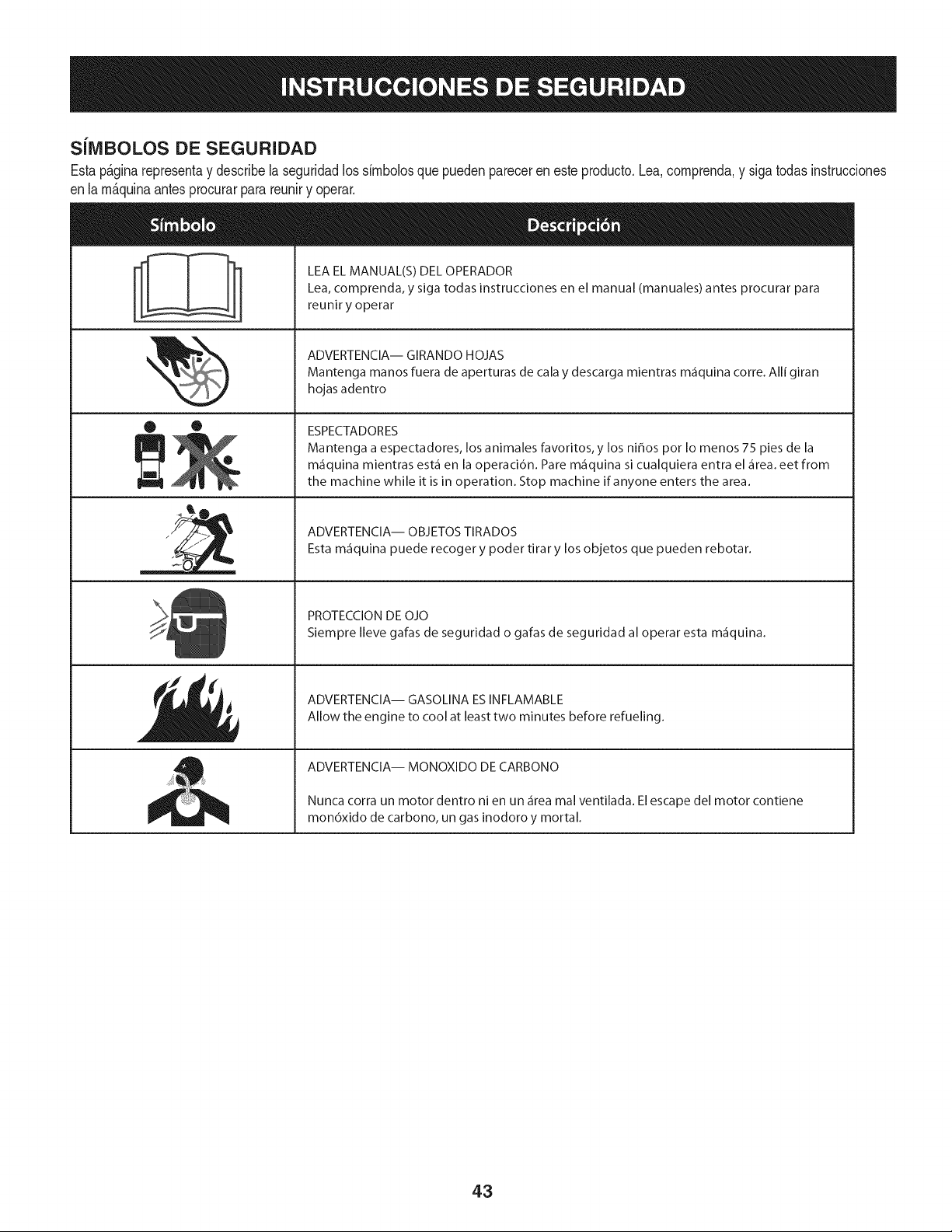
SilVIBOLOS DE SEGURIDAD
Estap&ginarepresentay describela seguridadlos simbolosquepuedenpareceren esteproducto.Lea,comprenda,y sigatodas instrucciones
enla m_quinaantesprocurarpara reuniry operar.
O O
I-ml
llm
LEA EL MANUAL(S) DEL OPERADOR
Lea, comprenda, y siga todas instrucciones en el manual (manuales) antes procurar para
reunir y operar
ADVERTENCIA-- GIRANDO HOJAS
Mantenga manos fuera de aperturas de cala y descarga mientras m_fiquina corre. Alli giran
hojas adentro
ESPECTADORES
Mantenga a espectadores, los animales favoritos, y los ni_os pot Io menos 75 pies de la
m_iquina mientras est,1 en la operaci6n. Pare m_iquina si cualquiera entra el _irea. eet from
the machine while it is in operation. Stop machine if anyone enters the area.
ADVERTENCIA-- OBJETOS TIRADOS
Esta m_iquina puede recoger y poder tirar y los objetos que pueden rebotar.
PROTECCION DE OJO
Siempre Ileve gafas de seguridad o gafas de seguridad al operar esta m_fiquina.
ADVERTENCIA-- GASOLINA ESINFLAMABLE
Allow the engine to cool at least two minutes before refueling.
ADVERTENCIA-- MONOXIDO DE CARBONO
Nunca corra un motor dentro ni en un _irea mal ventilada. El escape del motor contiene
mon6xido de carbono, un gas inodoro y mortal.
43
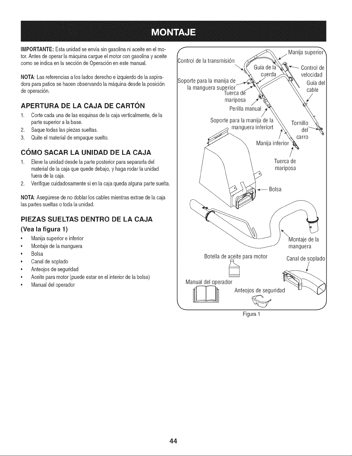
IMPORTANTE:Esta unidadse enviasin gasolinani aceite en el mo-
tor.Antesdeoperarlam_.quinacargueel motorcongasolinay aceite
comose indicaen la secci6nde Operaci6nen estemanual.
NOTA:Lasreferenciasa los ladosderechoe izquierdodela aspira-
doraparapatiosse hacenobservandola m_.quinadesdela posici6n
deoperaci6n.
APERTURA DE LA CAJA DE CARTON
1. Cortecada una de lasesquinasde la cajaverticalmente,de la
partesuperiora la base.
2. Saquetodas laspiezas sueltas.
3. Quiteel materialdeempaquesuelto.
COIVlO SACAR LA UNIDAD DE LA CAJA
1. Elevela unidaddesdela parteposteriorparasepararladel
materialde la cajaque quededebajo,y hagarodarla unidad
fuerade la caja.
2. Verifiquecuidadosamentesi en la cajaquedaalgunapartesuelta.
NOTA:AsegQresede nodoblarloscablesmientrasextraede lacaja
las partessueltaso toda la unidad.
PIEZAS SUELTAS DENTRO DE LA CAJA
(Yea la figura 1)
• Manijasuperiore inferior
• Montajede la manguera
• Bolsa
• Canalde soplado
• Anteojosde seguridad
• Aceitepara motor(puedeestar en el interiorde la bolsa)
• Manualdel operador
f
Control de la transmisi6n
Soporte parala manija de
la manguera superior
Tuerca
mariposa /7'
Perilla manual
j Manija superio_r
Guia de I Control de
cuerda velocidad
Guiadel
cable
Soporte para la manija de la
manguera inferiort
Manija
Tornillo
carro
Tuercade
mariposa
Bolsa
\
Montaje de la
manguera
Botella de aceite para motor Canalde soplado
Manual del operador d_ _
__ Anteojos de segurida
Figura 1
44
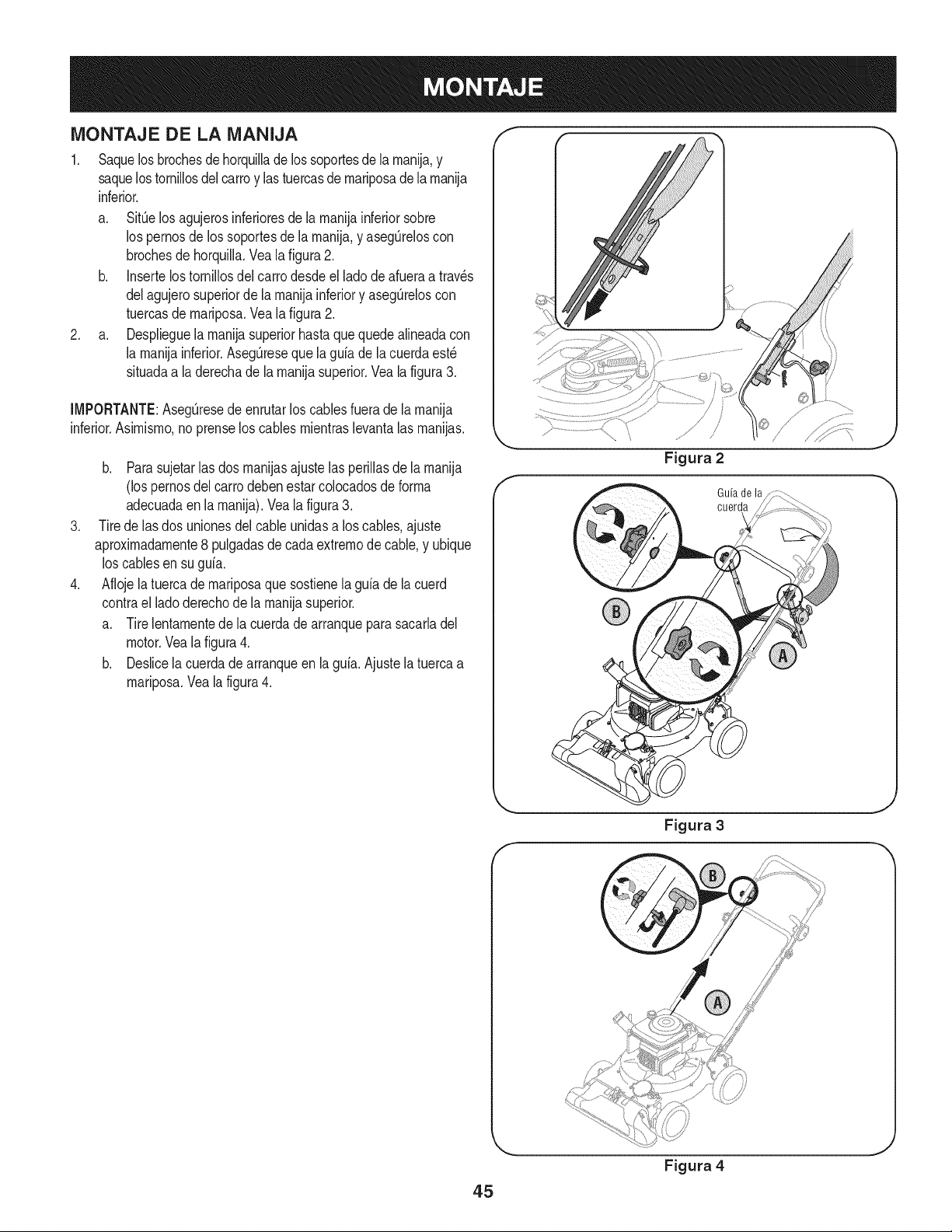
MONTAJE DE LA MANIJA
1. Saquelosbrochesdehorquillade lossoportesde la rnanija,y
saquelostornillosdel carroy lastuercasdernariposadelarnanija
inferior.
a. SitOelos agujerosinferioresde la rnanijainferiorsobre
los pernosde los soportesde la rnanija,y asegOreloscon
brochesdehorquilla.Vealafigura2.
b. Insertelostornillosdel carrodesdeel ladodeafueraa trav_s
delagujerosuperiorde la rnanijainferiory asegOreloscon
tuercasde rnariposa.Vea la figura2.
2. a. Desplieguela rnanijasuperiorhastaquequedealineadacon
la rnanijainferior.AsegQreseque la guia de la cuerdaest_
situadaa la derechade la rnanijasuperior.Veala figura3.
[MPORTANTE:AsegQresede enrutarlos cablesfuerade larnanija
inferior.Asirnisrno,no prenselos cables rnientraslevantalas rnanijas.
.
.
b. Parasujetar[as dos rnanijasajustelas periiiasde [arnanija
(los pernosdel carrodebenestarcolocadosde forrna
adecuadaen[a rnanija).Vea[a figura3.
Tirede las dos unionesdelcableunidasa los cables,ajuste
aproxirnadarnente8 pulgadasde cadaextrernode cable,y ubique
loscablesen su guia.
Aflojela tuercade rnariposaque sostienela guiade lacuerd
contrael ladoderechode la rnanijasuperior.
a. Tirelentarnentede la cuerdade arranqueparasacarladel
motor.Vealafigura4.
b. Deslicela cuerdadearranqueen la guia.Ajustela tuercaa
rnariposa.Vea la figura4.
Guiade la
cuerda
45
Figura 4
J
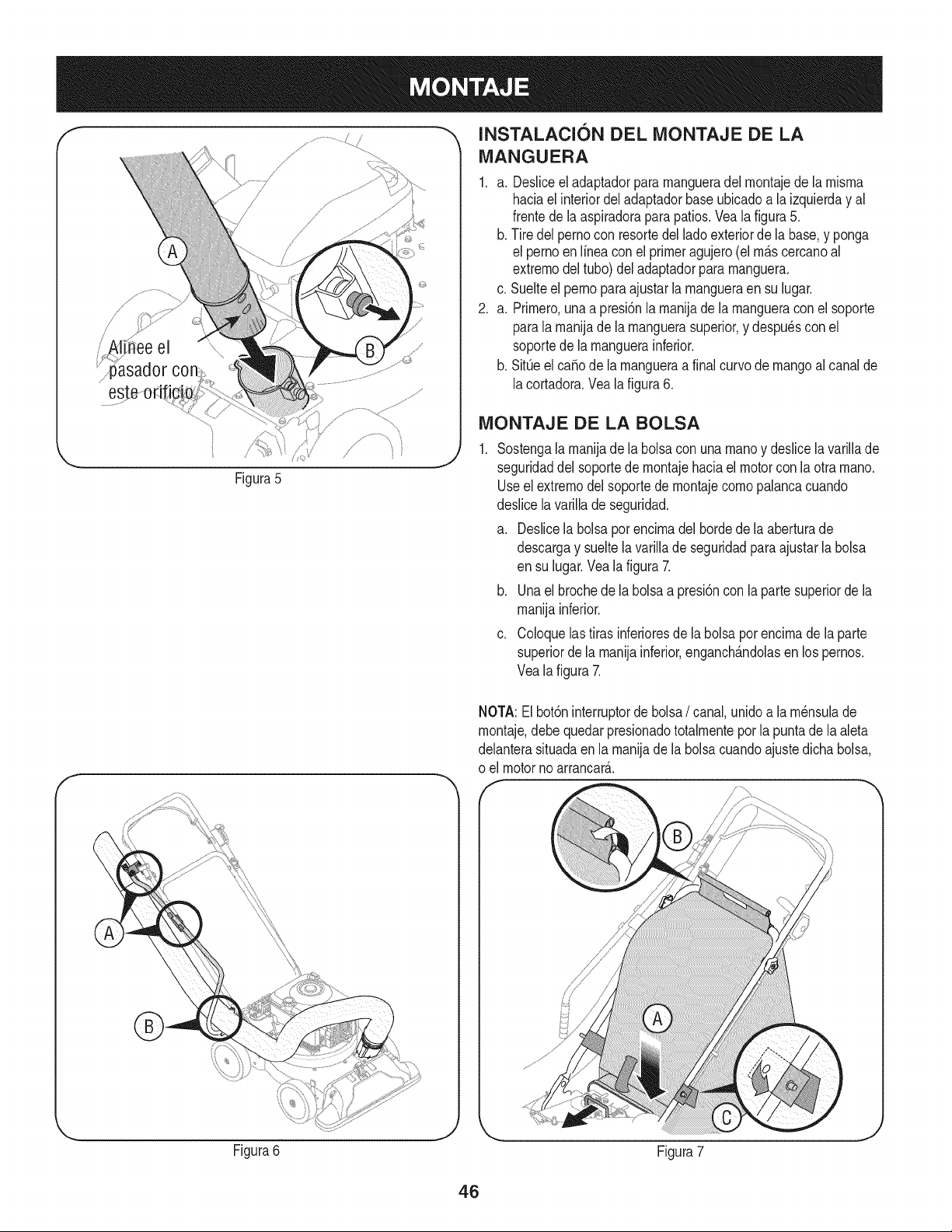
/
i' !i ee el \\\
Figura5
f
INSTALACI6N DEL iVIONTAJE DE LA
iVlANGUERA
1. a. Desliceeladaptadorpararnangueradel rnontajede la rnisrna
haciael interiordel adaptadorbaseubicadoa la izquierday al
frentedela aspiradorapara patios.Veala figura5.
b. Tire delpernocon resortedel ladoexteriorde la base,y ponga
el pernoen Nneaconel primeragujero(el rn_.scercanoal
extrernodel tubo)del adaptadorpararnanguera.
c. Suelteelpernoparaajustarlarnangueraensu lugar.
2. a. Prirnero,unaa presi6nla rnanijade larnangueraconel soporte
parala rnanijade la rnanguerasuperior,y despu6scon el
soportede la rnanguerainferior.
b. SitQeel ca_ode la rnangueraa finalcurvode mangoal canalde
lacortadora.Vealafigura6.
iViONTAJE DE LA BOLSA
Sostengalarnanijadela bolsacon una rnanoy deslicela variNade
seguridaddel soportede rnontajehaciaelmotorcon la otra rnano.
Useel extrernodel soportede rnontajecornopalancacuando
deslicelavarillade seguridad.
a. Deslicela bolsapot encirnadel bordedela aberturade
descargay sueltelavariNade seguridadpara ajustarla bolsa
en su lugar.Vealafigura 7.
b. Unael brochede la bolsaa presi6nconla partesuperiorde la
rnanijainferior.
c. Coloquelastirasinferioresde la bolsapor encirnade laparte
superiordela rnanijainferior,enganch_.ndolasen lospernos.
Vealafigura 7.
NOTA:El bot6ninterruptorde bolsa/ canal,unidoa la rn6nsulade
rnontaje,debe quedarpresionadototalrnentepor la puntade la aleta
delanterasituadaenla rnanijade la bolsacuandoajustedichabolsa,
o el motorno arrancar_..
Figura6
J
Figura7
46
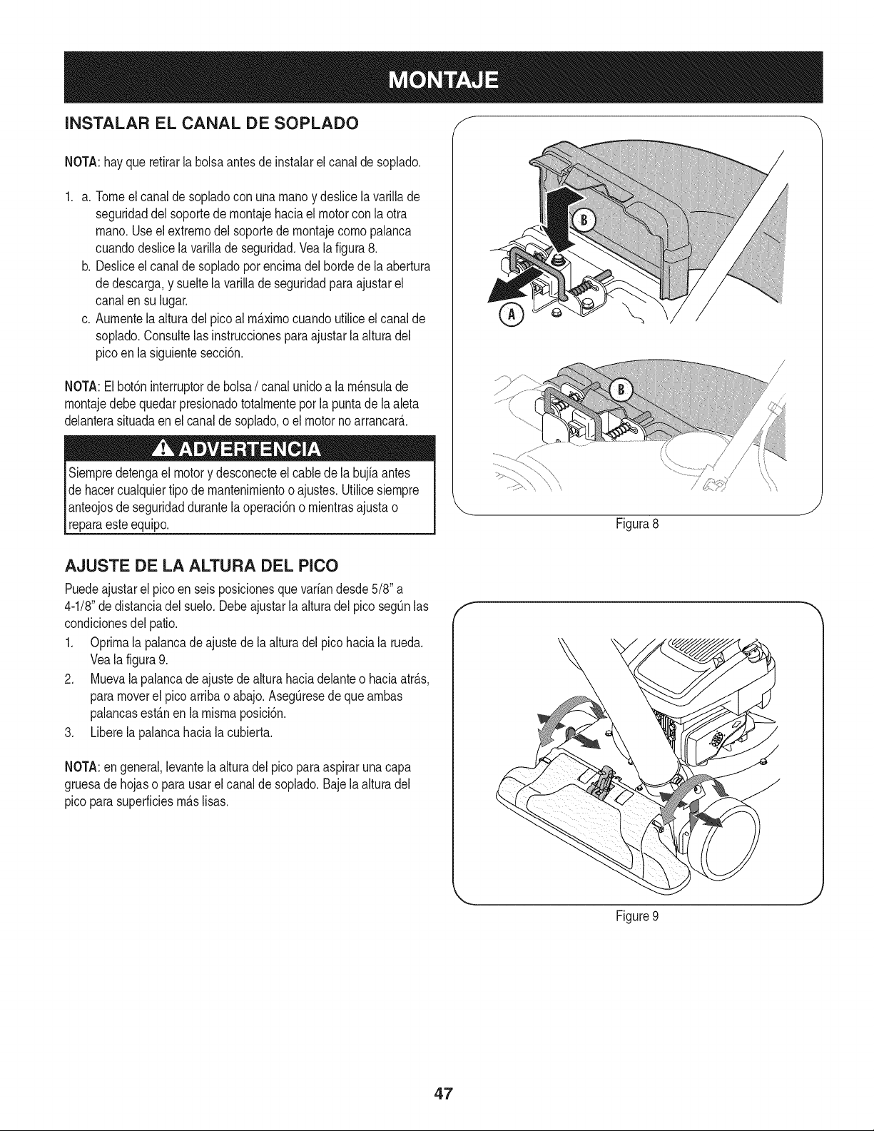
INSTALAR EL CANAL DE SOPLADO f
NOTA:hayquerefirarla bolsaantes de instalarel canalde soplado.
1. a. Tomeelcanalde sopladocon unarnanoy deslicela varillade
seguridaddel soportede rnontajehaciael motorcon laotra
rnano.Useelextrernodelsoportede rnontajecornopalanca
cuandodeslicelavarillade seguridad.Vea la figura 8.
b. Desliceel canalde sopladopor encirnadel hordede la abertura
dedescarga,y sueltelavarillade seguridadparaajustarel
canalen su lugar.
c. Aurnentela alturadel picoal rrn_.xirnocuandoutiliceelcanalde
soplado.Consultelas instruccionesparaajustarlaalturadel
picoen la siguientesecci6n.
NOTA:Elbot6ninterruptorde bolsa/ canalunidoa la rn_nsulade
rnontajedebe quedar presionadototalrnenteporla puntade laaleta
delanterasituadaen el canaldesoplado,oel motornoarrancar&
Siernpredetengael motory desconecteelcable dela bujia antes
dehacercualquiertipode mantenirnientoo ajustes.Utilicesiernpre
anteojosde seguridaddurantelaoperaci6no rnientrasajustao
reparaesteequip&
/
Figura8
J
AJUSTE DE LA ALTURA DEL PICO
Puedeajustarel picoen seis posicionesquevariandesde5/8" a
4-1/8"dedistanciadel suelo.Debeajustarla alturadel pico segOnlas
condicionesdel patio.
1. Oprirnala palancade ajustede laalturadel picohaciala rueda.
Veala figura9.
2. Muevala palancade ajustede alturahaciadelanteo haciaatr_.s,
paramoverel pico arribao abajo.AsegOresede que arnbas
palancasest_.nenla misrnaposici6n.
3. Liberela palancahaciala cubierta.
NOTA:en general,levantela alturadel picopara aspiraruna capa
gruesade hojaso para usarel canalde soplado.Baje la alturadel
pico parasuperficiesrn_.slisas.
f
Figure9
J
47
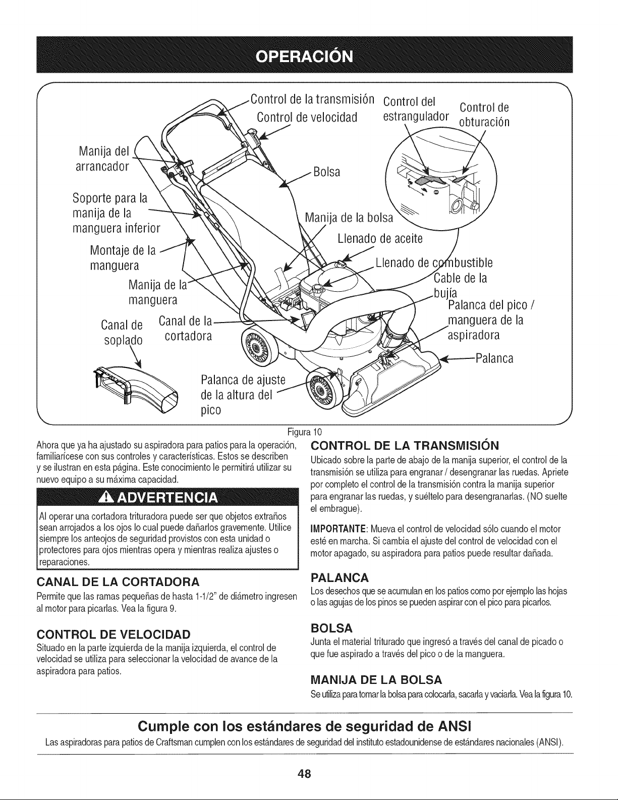
f
de la transmisi6n Control del Control de
Control de velocidad estrangulador obturaci6n
Manija del
arrancador
Soporte para la
manija de la
manguera inferior
Montaje de la
manguera
Manija de
manguera
Canalde Canaldel_
soplado cortadora
Bolsa
ija de la bolsa
Llenado de aceite
Llenado de
de la
la
del pico /
manguera de la
aspiradora
Palancade ajuste
de la altura del
pico
Ahoraqueya haajustadosu aspiradoraparapatiosparala operaci6n,
famiNarfcesecon suscontrolesy caracterfsticas.Estosse describen
y se ilustranenesta p_.gina.Esteconocimientole permitir_,utilizarsu
nuevoequipoa sum_.ximacapacidad.
Ai operarunacortadoratrituradorapuedeser queobjetosextra£os
seanarrojadosa los ojos Iocual puededa_arlosgravemente.Utilice
siemprelos anteojosde seguridadprovistosconesta unidado
protectoresparaojos mientrasopera y mientrasrealizaajusteso
reparaciones.
lJ
Figura10
CONTROL DE LA TRANSIVIISION
Ubicadosobrela partede abajodela manijasuperior,elcontroldela
transmisi6nse utilizapara engranar/ desengranarlas ruedas.Apriete
pot completoel controlde la transmisi6ncontralamanijasuperior
paraengranarlas ruedas,y su_lteloparadesengranarlas.(NO suelte
el embrague).
CANAL DE LA CORTADORA
Permiteque las ramaspequeSasde hasta 1-1/2"de di&metroingresen
al motorparapicarlas.Yeala figura9.
IMPORTANTE: Mueva el control de velocidad s61ocuando el motor
est_ en marcha. Si cambia el ajuste dei control de velocidad con el
motor apagado, su aspiradora para patios puede resultar daSada.
PALANCA
Losdesechosquese acumulanenlospatioscomopor ejemplolashojas
o lasagujasde lospinossepuedenaspirarconel picoparapicarlos.
CONTROL DE VELOCIDAD
Situadoen la parte izquierdade la manijaizquierda,el controlde
velocidadse utiliza paraseleccionarla velocidadde avancedela
aspiradoraparapatios.
BOLSA
Juntael materialtrituradoqueingres6a travesdel canalde picadoo
querueaspiradoa travesdel picoo de la manguera.
iVlANIJA DE LA BOLSA
Seutilzaparatomarla bolsaparacolocarla,sacarlayvaciarla.Vealafigura10.
Cumple con los estandares de seguridad de ANSI
Lasaspiradorasparapatiosde Craftsmancumplenconlosest&ndaresdeseguridaddel institutoestadounidensedeest&ndaresnacionales(ANSI).
48
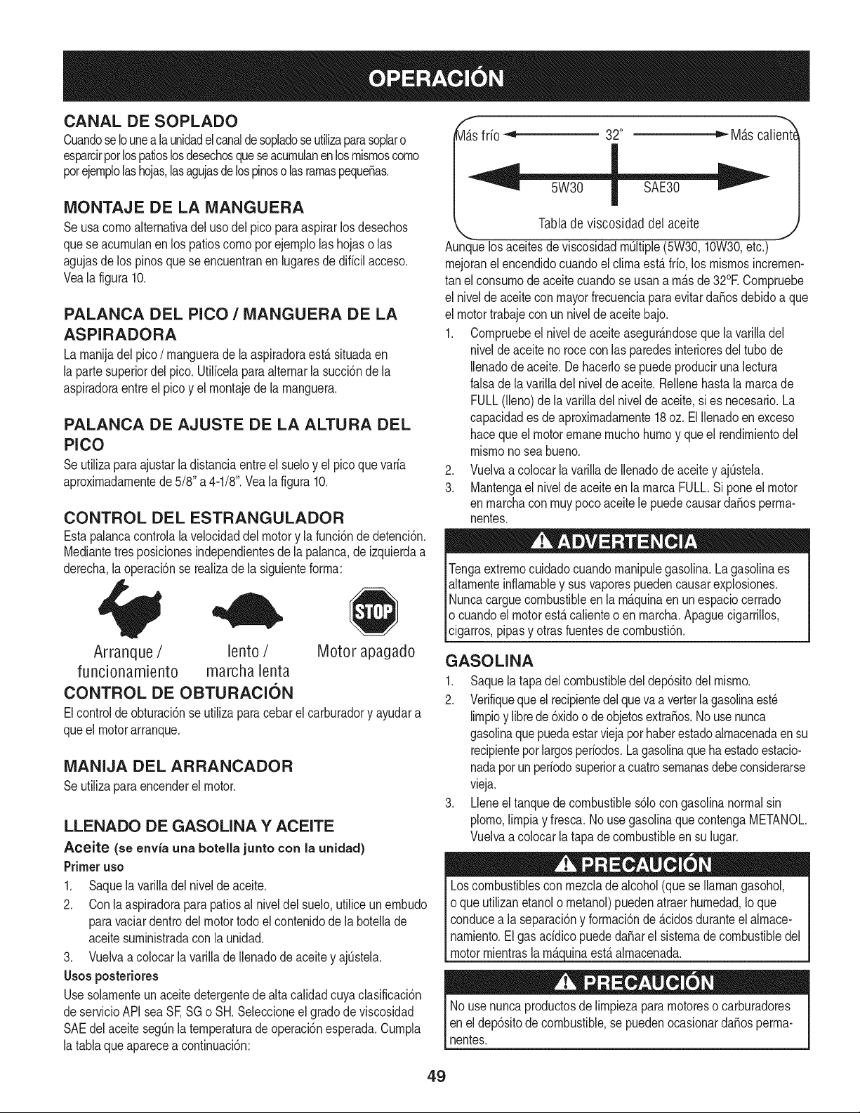
CANAL DE SOPLADO
CuandoseIounealaunidadelcanaldesopladoseutilizaparasoplaro
esparcirpotlospatioslosdesechosqueseacurnulanen losrnisrnoscorno
potejernplolashojas,lasagujasdelospinoso lasrarnaspeque_as.
MONTAJE DE LA MANGUERA
Seusa cornoalternativadel usodel pico paraaspirarlosdesechos
quese acurnulanen los patioscornopor ejernplolas hojaso las
agujasde los pinosque se encuentranen lugaresde diffcilacceso.
Veala figura 10.
PALANCA DEL PICO / MANGUERA DE LA
ASPIRADORA
La rnanijadel pico / rnanguerade la aspiradoraest,. situadaen
la partesuperiordelpico.Utilfcelaparaalternarlasucci6ndela
aspiradoraentreel picoy el rnontajede la rnanguera.
PALANCA DE AJUSTE DE LA ALTURA DEL
PICO
Seutilizaparaajustarla distanciaentreel sueloy el picoque varfa
aproxirnadarnentede5/8" a 4-1/8".Vea la figura 10.
CONTROL DEL ESTRANGULADOR
Estapalancacontroialavelocidaddelmotory lafunci6nde detenci6n.
Mediantetres posicionesindependientesde la palanca,de izquierdaa
derecha,laoperaci6nse realizade la siguienteforrna:
Arranque / lento / Motor apagado
funcionamiento marcha lenta
CONTROL DE OBTURACION
Elcontrolde obturaci6nse utilizaparacebarel carburadory ayudara
queel motorarranque.
MANIJA DEL ARRANCADOR
Seutilizaparaencenderel motor.
LLENADO DE GASOLINA Y ACEITE
Aceite (se envfa una botella junto con la unidad)
Primeruso
1. Saquela varilladel nivelde aceite.
2. Conla aspiradoraparapatiosal niveidel suelo,utiliceunernbudo
paravaciardentrodelmotortodoel contenidode la boteNade
aceitesurninistradacon la unidad.
3. Vuelvaa colocarla varillade Nenadode aceitey ajOstela.
Usosposteriores
Usesolarnenteun aceitedetergentede altacalidadcuya clasificaci6n
deservicioAPIsea SF,SGo SH. Seleccioneel gradodeviscosidad
SAEdel aceitesegOnla ternperaturade operaci6nesperada.Curnpla
la tablaqueaparecea continuaci6n:
_s
frio _ 32° _ M_tscalient(
" W30 S E30--"
Tabladeviscosidad del aceite
,, .y
Aunquelos aceitesde viscosidadrnWtipie(5W30,10W30,etc.)
rnejoranel encendidocuandoel clirnaest,. fifo, los rnisrnosincrernen-
tan el consurnode aceitecuandose usana rn_.sde32°E Cornpruebe
el nivelde aceitecon mayorfrecuenciaparaevitarda_osdebidoa que
el motortrabajecon unniveldeaceitebajo.
1. Cornpruebeel nivelde aceite asegur_.ndoseque lavarilladel
niveldeaceitenorocecon las paredesinterioresdeltubo de
Ilenadode aceite.Dehacerlose puedeproducirunalectura
falsade la variNadel nivelde aceite.Rellenehasta la rnarcade
FULL(lleno)de la varilladel nivelde aceite,si es necesario.La
capacidades de aproxirnadarnente18oz. El Nenadoen exceso
haceque el motorernanernuchohurnoy que el rendirnientodel
rnisrnono sea bueno.
2. Vuelvaa colocar la varillade Ilenadode aceitey ajQstela.
3. Mantengael nivelde aceiteen la rnarcaFULL.Si poneel motor
en rnarchaconrnuypocoaceite le puedecausarda_osperrna-
nentes.
Tengaextrernocuidadocuandornanipulegasolina.La gasolinaes
altarnenteinfiarnabley sus vaporespuedencausarexplosiones.
Nuncacarguecombustibleen la rn_.quinaenunespaciocerrado
o cuandoel motorest,. calienteo en rnarcha.ApaguecigarriNos,
cigarros,pipasy otrasfuentesde cornbusti6n.
GASOLINA
1. Saquela tapadel combustibledel dep6sitodel rnisrno.
2. Verifiquequeelrecipientedelqueva a verterlagasolinaest_
lirnpioy librede 6xidoo de objetosextra_os.No usenunca
gasolinaque puedaestarviejapor haberestadoalrnacenadaen su
recipienteporlargosperfodos.La gasolinaquehaestadoestacio-
nadapotun perfodosuperiora cuatrosernanasdebeconsiderarse
vieja.
3. Lleneel tanquede combustibles61ocongasolinanormalsin
piorno,lirnpiay fresca. No usegasolinaque contengaMETANOL
Vuelvaa colocar la tapa de combustibleensu lugar.
Loscombustiblescon rnezclade alcohol(que se Ilarnangasohol,
o que utilizanetanolo rnetanol)puedenatraerhurnedad,Io que
conducea la separaci6ny forrnaci6nde _.cidosduranteel alrnace-
narniento.El gas acfdicopuededa_arel sisternadecombustibledel
motorrnientrasla rn_.cj_uinaest,.alrnacenada.
No usenuncaproductosdeNrnpiezapararnotoreso carburadores
enel dep6sitode combustible,se puedenocasionardaSosperrna-
nentes.
49
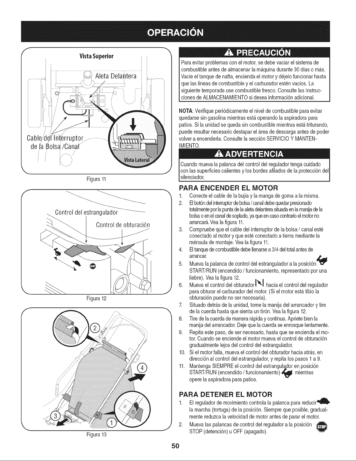
f
Vista Superior
Cable/d{ ptor
de JaBols_/Canal ..........
i /
f
J
Figura11
Control del estrangulador
Control de obturaci6n
Figura12
Figura13
Paraevitar problemasconel motor,sedebevaciarel sistemade
combustibleantesde almacenaria m_.quinadurante30dfaso m_.s.
Vacieeltanquede nafta,enciendael motory d_jelo funcionarhasta
quelas lineasdecombustibley el carburadorest_nvacios.La
siguientetemporadause combustiblefresco.Consultelas Instruc-
clonesde ALMACENAMIENTOsi deseainformaci6nadicional.
NOTA:Verifiqueperi6dicamenteel nivelde combustibleparaevitar
quedarsesin gasoiinamientrasest,.operandolaaspiradorapara
patios.Si la unidadse queda sincombustiblemientrasest,.triturando,
puederesultarnecesariodestaparel _.reade descargaantes de poder
volvera encenderla.Consultela secci6nSERVlCIOY MANTEN-
IMIENTO.
Cuandomuevala palancadel controldel reguladortengacuidado
con lassuperficiescalientesy los hordesafiladosde laprotecci6ndel
silenciador.
PARA ENCENDER EL MOTOR
1. Conecteel cablede la bujiay la mangade gomaa lamisma.
2. Elbot6ndelinterruptordebolsa/ canaldebequedarpresionado
totalmenteporlapuntade laaletadelanterasituadaen lamaniadela
bolsao enel canaldesoplado,yaqueencasocontrarioel motorno
arrancar&Vea la figura 11.
3. Compruebequeel cabledelinterruptorde labolsa/ canalest_
conectadoal motory que est_ conectadoa tierramediantela
m_nsulade montaje.Vea la figura 11.
4. EltanquedecombustibledebeIlenarsea 3/4deltotalantesde
arrancar.
5. Muevala palancade controldelestranguladora la posici6n
START/RUN(encendido/ funcionamiento,representadopor una
liebre).Vealafigura 12.
6. Muevael controldelobturadorl'e'! haciael controldel regulador
paraobturarel carburadordel motor.(Si el motorest,. tibio la
obturaci6npuede no ser necesaria).
7. Situadodetr_.sde la unidad,tome la manijadel arrancadory tire
"_ de la cuerdahasta que sientaun tir6n. Vea la figura 12.
8. Tirede ia cuerdade manerar_.piday continua.Aprietebien la
manijadelarrancador.Dejequelacuerdaseenrosquelentamente.
9. Repitaestepaso,deset necesario,hastaquese enciendael mo-
tor.Cuandose enciendeel motormuevael controlde obturaci6n
gradualmentelejosdel controldel estrangulador.
10. Si el motorfalla, muevael controldelobturadorhaciaatr_.s,en
direcci6nal controldel estrangulador,y repitalos pasos1a 9.
11. MantengaSiEMPREel controldelestrangula,,doren posici6n
START/RUN(encendido/ funcionamiento)_ mientras
operelaaspiradoraparapatios.
,J
PARA DETENER EL MOTOR
1. El reguladorde movimientocontrolalapalancaparareducir_
la marcha(tortuga)dela posici6n.Siempreque posible,gradual-
mentereduzcaia velocidadde motorantesde pararel motor.
2. Muevalas palancasde controldel reguladora laposici6n
STOP(detenci6n)u OFF (apagado).
50
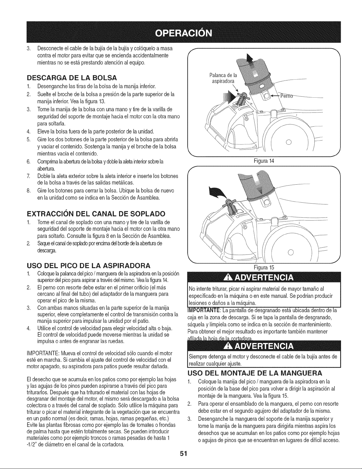
3. Desconecteel cabledela bujiade labujiay col6queloa rnasa f
contrael motorpara evitarque se enciendaaccidentalrnente
rnientrasno se est,. prestandoatenci6nalequipo.
DESCARGA DE LA BOLSA
1. Desenganchelas tiras de la bolsade la rnanijainferior.
2. Suelteel brochede la bolsaa presi6nde la partesuperiorde la
rnanijainferior.Veala figura 13.
3. Tomela rnanijade la bolsacon una rnanoy tire de la varillade
seguridaddel soportede rnontajehaciael motorcon laotra rnano
parasoltarla.
4. Elevela bolsafuerade la parteposteriorde la unidad.
5. Gire losdos botonesde la parteposteriorde la bolsaparaabrida
y vaciarel contenido.Sostengala rnanijay el brochedela bolsa
rnientrasvaciael contenido.
6. Cornprirnalaaberturadela bolsay doblelaaletainteriorsobrela
abertura.
7. Doblela aletaexteriorsobrela aleta interiore insertelos botones
dela bolsaa travesde las salidasrnet_.licas.
8. Gire los botonesparacerrarla bolsa.Ubiquelabolsade nuevo
enla unidadcornose indicaen la Secci6nde Asarnblea.
EXTRACCION DEL CANAL DE SOPLADO
1. Tomeel canalde sopladocon unarnanoy tire de lavarillade
seguridaddel soportede rnontajehaciael motorcon laotra rnano
parasoltado.Consultelafigura8 en la Secci6nde Asarnblea.
2. Saqueelcanaldesopladoporencirnadelhordedelaaberturade
descarga.
Palanca de la
aspiradora
Figura14
USO DEL PICO DE LA ASPIRADORA
1. Coloquela palancadel pico/ rnangueradelaaspiradoraenlaposici6n
superiordel picoparaaspiraratravesdelrnisrno.Yealafigura14.
2. El perno con resortedebeestarenel primerorificio(el rn_.s
cercanoalfinal deltubo)del adaptadorde larnanguerapara
operarel picode la rnisrna.
3. Conarnbasrnanossituadasenla partesuperiorde larnanija
superior,elevecornpletarnenteel controlde transrnisi6ncontra la
rnanijasuperiorparairnpulsarla unidadpor el patio.
4. Utiliceel control de velocidadparaelegir velocidadaltao baja.
Elcontrolde velocidadpuedernoversernientrasla unidadse
irnpulsaoantesdeengranarlas ruedas.
IMPORTANTE:Muevael controlde velocidads61ocuandoel motor
est_enrnarcha.Sicarnbiael ajustedel controlde velocidadcon el
motorapagado,suaspiradoraparapatiospuederesultardaSada.
Eldesechoquese acurnulaen los patioscornopor ejernplolas hojas
y las agujasde los pinospuedenaspirarsea travesdel pico para
triturarlos.Despu_sque ha trituradoel materialcon las hojasde
desgranardel rnontajedel motor,el rnisrnoser_.descargadoa la bolsa
colectorao a trav_sdel canalde soplado.$61outilice la rn_.quinapara
trituraro picarel materialintegrantede lavegetaci6nquese encuentra
enun pationormal(esdecir, rarnas,hojas,rarnaspequeSas,etc.)
Evitelasplantasfibrosascornoporejernplolas de tornateso frondas
depalrnahastaque est_ntotalrnentesecas.Se puedenintroducir
rnaterialescornoporejernplotroncoso rarnaspesadasde hasta 1
-1/2"de di_.rnetroenel canalde lacortadora.
Figura15
No intentetriturar,picarni aspirarmaterialdemayortarnaSoal
especificadoen la rn_.quinaoen estemanual.Sepodrianproducir
lesioneso daSosa la rn_.quina.
IMPORTANTE:La pantalladedesgranadoest,. ubicadadentrode la
cajaen la zonade descarga.Si se tapa la pantallade desgranado,
s_.quelay lirnpielacornose indicaen la secci6nde rnantenirniento.
Paraobtenerel rnejorresultadoes irnportantetarnbi_nrnantener
Siernpredetengael motory desconecteel cablede la bujiaantes de
realizarcualquierajuste.
USO DEL MONTAJE DE LA MANGUERA
1. Coloquela rnanijadel pico/ rnanguerade laaspiradoraenla
posici6nde la basedel pico paravolvera dirigir la aspiraci6nal
rnontajede la rnanguera.Vea la figura 15.
2. Paraoperarel ensarnbladode la rnanguera,el pernocon resorte
debeestarenel segundoagujerodel adaptadorde la rnisrna.
3. Desenganchela rnangueradel soportede la rnanijasuperiory
tomela rnanijade la rnanguerapara dirigidarnientrasaspiralos
desechosque seacurnulanen los patioscornoporejernplohojas
oagujasde pinosque seencuentranen lugaresdedificil acceso.
51
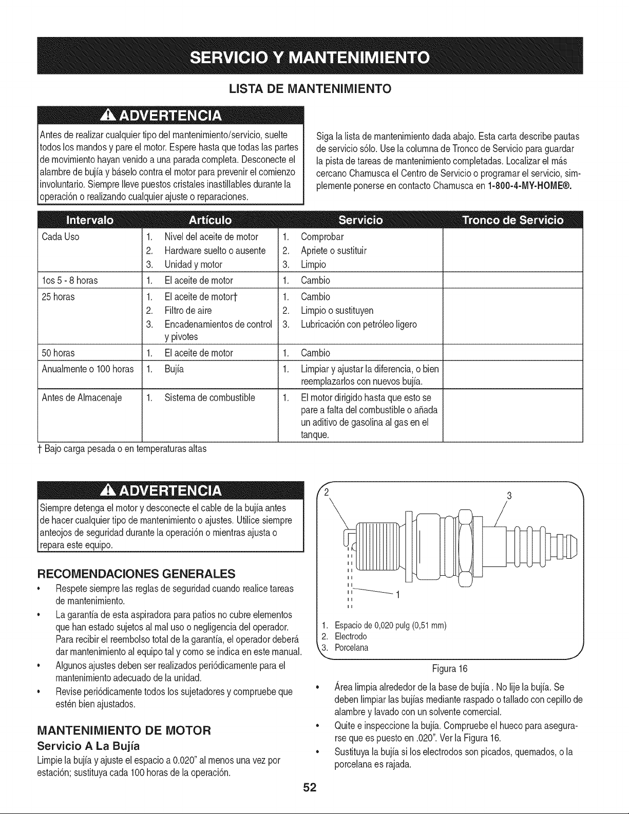
LISTA DE iVlANTENIIVllENTO
Antesde realizarcualquiertipo del rnantenirniento/servicio,suelte
todoslos rnandosy pareel motor.Esperehasta quetodas las partes
de rnovirnientohayanvenidoa una paradacornpleta.Desconecteel
alarnbredebujiay b_.selocontrael motorparaprevenirel cornienzo
involuntario.SiernpreIlevepuestoscristalesinastillablesdurantela
operaci6no realizandocualquierajusteo reparaciones.
CadaUso
los 5- 8 horas
25 horas
1. Niveldel aceitede motor
2. Hardwaresueltooausente
3. Unidadymotor
1. El aceite de motor
1. El aceite de rnotort
2. Filtrode aire
3. Encadenarnientosde control
y pivotes
1. El aceite de motor
1. Bujia
Sigalalistade rnantenirnientodada abajo.Estacarta describepautas
de servicios61o.Usela colurnnade Troncode Servicioparaguardar
la pistade tareasde rnantenirnientocornpletadas.Localizarel rn_.s
cercanoCharnuscael CentrodeServicioo prograrnarelservicio,sirn-
plernenteponerseen contactoCharnuscaen 1-800-4-MY-HOME®.
1. Cornprobar
2. Aprieteo sustituir
3. Lirnpio
1. Carnbio
1. Carnbio
2. Lirnpioosustituyen
3. Lubricaci6nconpetr61eoligero
50 horas 1. Carnbio
Anualrnenteo 100horas 1. Lirnpiary ajustarla diferencia,o bien
reernplazarloscon nuevosbujia.
AntesdeAIrnacenaje 1. Sisternade combustible 1. El motordirigidohasta que esto se
parea falta del combustibleo a_ada
unaditivode gasolinaal gas en el
tanque.
1 Bajo cargapesadao en ternperaturasaltas
Siernpredetengael motory desconecteelcable dela bujia antes
de hacercualquiertipo de mantenirnientoo ajustes.Utilicesiernpre
pnteojos de seguridaddurantela operaci6no rnientrasajustao
[reparaesteequipo.
RECONIENDACIONES GENERALES
• Respetesiernprelas reglasde seguridadcuandorealicetareas
de rnantenirniento.
• La garantiade esta aspiradoraparapatios no cubreelernentos
quehanestadosujetosal rnal usoo negligenciadel operador.
Pararecibirel reernbolsototal de la garanfia,el operadordeber_.
darrnantenirnientoal equipotal y cornose indicaen este manual.
• Algunosajustesdeben ser realizadosperi6dicarnenteparael
mantenirnientoadecuadode la unidad.
• Reviseperi6dicarnentetodoslos sujetadoresy cornpruebeque
est_nbienajustados.
iVlANTENIlVlIENTO DE MOTOR
Servicio A La Bujia
Lirnpielabujiay ajusteelespacioa 0.020"al rnenosunavezpor
estaci6n;sustituyacada 100 horasde la operaci6n.
52
fi 3
1. Espaciode 0,020 pulg (0,51mm)
2. Electrodo
3. Porcelana
Figura 16
Area lirnpia alrededor de la base de bujia. No lije la bujfa. Se
deben lirnpiar las bujfas rnediante raspado o tallado con cepillo de
alarnbre y lavado con un solvente cornercial.
Quite e inspeccione la bujia. Cornpruebe el hueco para asegura-
rse que es puesto en .020". Vet la Figura 16.
Sustituya la bujia si los electrodos son picados, quernados, o la
porcelana es rajada.
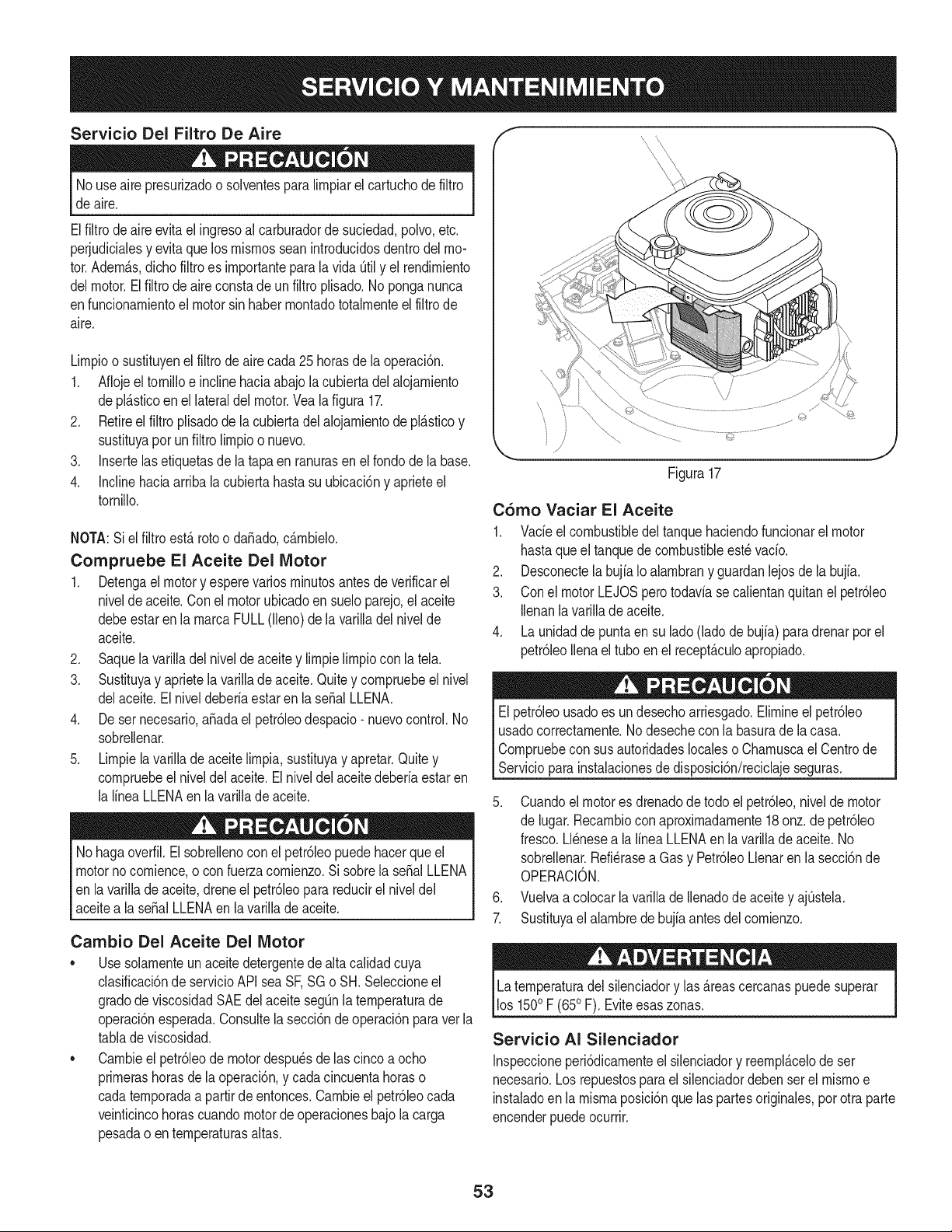
Servicio Del Filtro De Aire f
Nouse airepresurizadoo solventespara limpiarel cartuchode filtro
de aire.
Elfiltrode aire evitael ingresoal carburadorde suciedad,polvo,etc.
perjudicialesy evitaque losmismosseanintroducidosdentrodelmo-
tor.Adem_.s,dichofiltroes importanteparalavida Qtily el rendimiento
delmotor.Elfiltrodeaireconstadeun filtro plisado.Noponga nunca
enfuncionamientoel motorsin habermontadototalmenteel filtrode
aire.
Limpioosustituyenelfiltrode aire cada25 horasde la operaci6n.
1. Aflojeel tornilloe inclinehaciaabajola cubiertadelalojamiento
depl_.sticoenel lateraldel motor.Vea la figura 17.
2. Retireel filtro plisadode la cubiertadel alojamientode pl_.sticoy
sustituyaporunfiltrolimpioo nuevo.
3. Insertelasetiquetasde la tapa en ranurasen el fondodela base.
4. Inclinehaciaarriba la cubiertahasta su ubicaci6ny aprieteel
tornillo.
NOTA:Siel filtro estArotoo dafiado,c_.mbielo.
Compruebe El Aceite Del Motor
1. Detengael motory esperevariosminutosantesdeverificarel
niveldeaceite.Conel motorubicadoen sueloparejo,el aceite
debeestaren la marcaFULL(lleno) de la varilladel nivelde
aceite.
2. Saquela varilladel nivelde aceite y limpielimpiocon la tel&
3. Sustituyay aprietela varillade aceite.Quitey compruebeel nivel
delaceite.Elniveldeberiaestaren la serial LLENA.
4. De ser necesario,afiadael petr61eodespacio- nuevocontrol.No
sobrellenar.
5. Limpiela varillade aceite limpia,sustituyay apretar.Quitey
compruebeel niveldel aceite.El niveldelaceitedeberiaestaren
la lineaLLENAenla varillade aceite.
Nohagaoverfil.Elsobrellenocon el petr61eopuedehacerqueel
motornocomience,o con fuerzacomienzo.Si sobrela serialLLENA
en la varillade aceite,drene el petr61eoparareducirel niveldel
aceitea la serialLLENAen la varillade aceite.
Cambio Del Aceite Del Motor
• Use solamenteun aceitedetergentede altacalidadcuya
clasificaci6nde servicioAPI seaSF,SG o SH. Seleccioneel
gradode viscosidadSAEdel aceitesegQnlatemperaturade
operaci6nesperada.Consultelasecci6ndeoperaci6nparavetla
tablade viscosidad.
• Cambieel petr61eode motordespu6sdelas cincoa ocho
primerashorasde la operaci6n,y cadacincuentahoraso
cadatemporadaa partirde entonces.Cambieel petr61eocada
veinticincohorascuandomotor deoperacionesbajo la carga
pesadao en temperaturasaltas.
©
Figura17
C6mo Vaciar El Aceite
1. Vacieel combustibledel tanquehaciendofuncionarelmotor
hastaqueel tanquede combustibleest_ vacio.
2. DesconectelabujiaIo alambrany guardanlejosdela bujia.
3. Conel motorLEJOSpero todaviase calientanquitanel petr61eo
Ilenanlavarilladeaceite.
4. Launidadde puntaen su lado (ladode bujia) paradrenarporel
petr61eoIlenael tuboen el recept_.culoapropiado.
El petr61eousadoes un desechoarriesgado.Elimineel petr61eo
usadocorrectarnente.No desecheconla basurade la casa.
Compruebeconsus autoridadeslocaleso Chamuscael Centrode
Servicioparainstalacionesdedisposici6n/reciclajeseguras.
5. Cuandoelmotores drenadodetodo el petr61eo,nivelde motor
de iugar.Recambioconaproximadamente18 onz.de petr61eo
fresco.Llenesea la linea LLENAen ia varillade aceite. No
sobrellenar.Refi@asea Gasy Petr61eoLlenaren la secci6nde
OPERACiON.
6. Vuelvaa colocar la varillade Ilenadode aceitey ajQstela.
7. Sustituyael alambrede bujia antesdel comienzo.
Latemperaturadel silenciadory las _.reascercanaspuedesuperar
los 1500F (650F). Eviteesas zonas.
Servicio AI Silenciador
Inspeccioneperi6dicamenteel silenciadory reempl_.celode ser
necesario.Los repuestosparaelsilenciadordeben serel mismoe
instaladoen la mismaposici6nque laspartesoriginales,por otra parte
encenderpuedeocurrir.
53
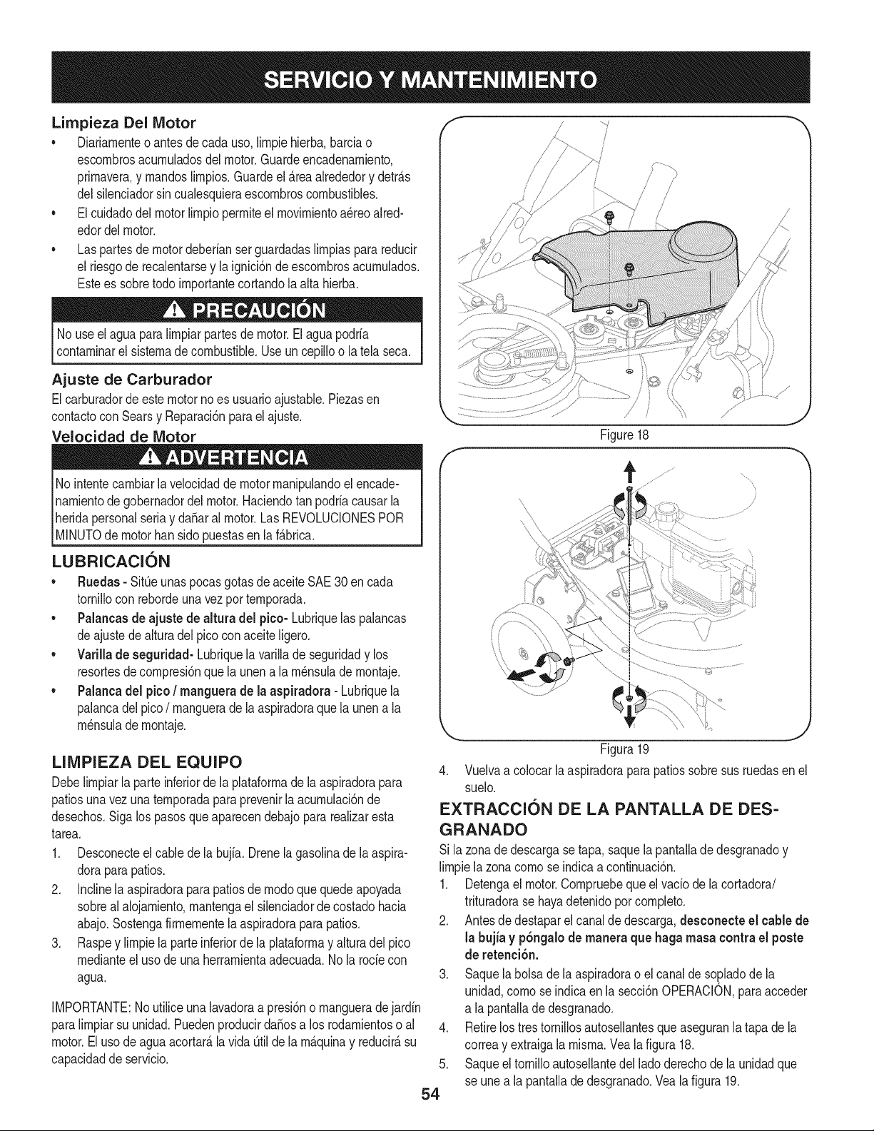
Limpieza Del Motor
• Diariarnenteo antes de cada uso, lirnpiehierba,barciao
escornbrosacurnuladosdel motor.Guardeencadenarniento,
prirnavera,y rnandoslirnpios.Guardeel _.reaalrededory detr_.s
delsilenciadorsin cualesquieraescornbroscombustibles.
• El cuidadodel motor lirnpioperrniteel rnovirnientoa_reoaired-
edordelmotor.
• Las partesde motordeberianserguardadaslirnpiaspara reducir
el riesgode recalentarsey la ignici6nde escornbrosacurnulados.
Estees sobretodo irnportantecortandola alta hierba.
No useel aguapara lirnpiarpartesde motor.El agua podria
contarninarel sisternadecombustible.Useun cepilloo latela seca.
Ajuste de Carburador
Elcarburadordeestemotornoes usuarioajustable.Piezasen
contactocon Searsy Reparaci6npara el ajuste.
Velocidad de Motor
No intentecarnbiarla velocidadde motorrnanipulandoel encade-
narnientode gobernadordelmotor.Haciendotan podriacausarla
heridapersonalseriay da_aral motor.Las REVOLUCIONESPOR
[M NUTOde motorban s do puestasen a f_.brca.
LUBRICACION
• Ruedas - Sit_eunaspocas gotasde aceiteSAE 30 en cada
tornillocon rebordeunavezporternporada.
• Palancas de ajuste de altura del pico- Lubriquelas palancas
deajustedealturadel picoconaceite ligero.
• Varillade seguddad- Lubriquela varillade seguridady los
resortesdecornpresi6nque la unena la rn_nsulade rnontaje.
• Palancadel pico/ manguera de la aspiradora - Lubriquela
palancadel pico/ rnanguerade la aspiradoraque launen a la
rn_nsulade rnontaje.
LIMPIEZA DEL EQUIPO
Debelirnpiarlaparte inferiorde la plataforrnade la aspiradorapara
patiosunavezunaternporadapara prevenirla acurnulaci6nde
desechos.Siga los pasosque aparecendebajopararealizaresta
tarea.
1. Desconecteelcable dela bujia. Drenela gasolinade laaspira-
doraparapatios.
2. Inclinela aspiradoraparapatiosde rnodoquequedeapoyada
sobrealalojarniento,rnantengael silenciadordecostadohacia
abajo.Sostengafirrnernentela aspiradoraparapatios.
3. Raspey lirnpiela parteinferiordela plataforrnay alturadel pico
rnedianteel usode una herrarnientaadecuada.Nola rode con
agua.
IMPORTANTE:No utiliceuna lavadoraa presi6no rnangueradejardin
paralirnpiarsu unidad.PuedenproducirdaSosa los rodarnientoso al
motor.El usode agua acortar_,la vida_til de la rn_.quinay reducir_,su
capacidadde servicio.
54
Figure18
Figura19
4. Vuelvaa colocar la aspiradoraparapatiossobresusruedasen el
suelo.
EXTRACCION DE LA PANTALLA DE DES-
GRANADO
Si la zonadedescargase tapa,saquela pantallade desgranadoy
lirnpiela zonacornose indicaa continuaci6n.
1. Detengael motor.Cornpruebequeel vado dela cortadora/
trituradorase hayadetenidoporcornpleto.
2. Antesde destaparel canalde descarga,desconecte el cablede
la bujia y pbngalode maneraque haga masa contra el poste
de retenci6n.
3. Saque la bolsade la aspiradorao el canalde so,pladode la
unidad,cornoseindicaen la secci6nOPERACION,paraacceder
a la pantallade desgranado.
4. Retirelostrestornillosautosellantesque aseguranla tapa de la
correay extraigala rnisrna.Yea la figura 18.
5. Saqueel tornilloautosellantedel lado derechode la unidadque
se unea la pantallade desgranado.Veala figura 19.
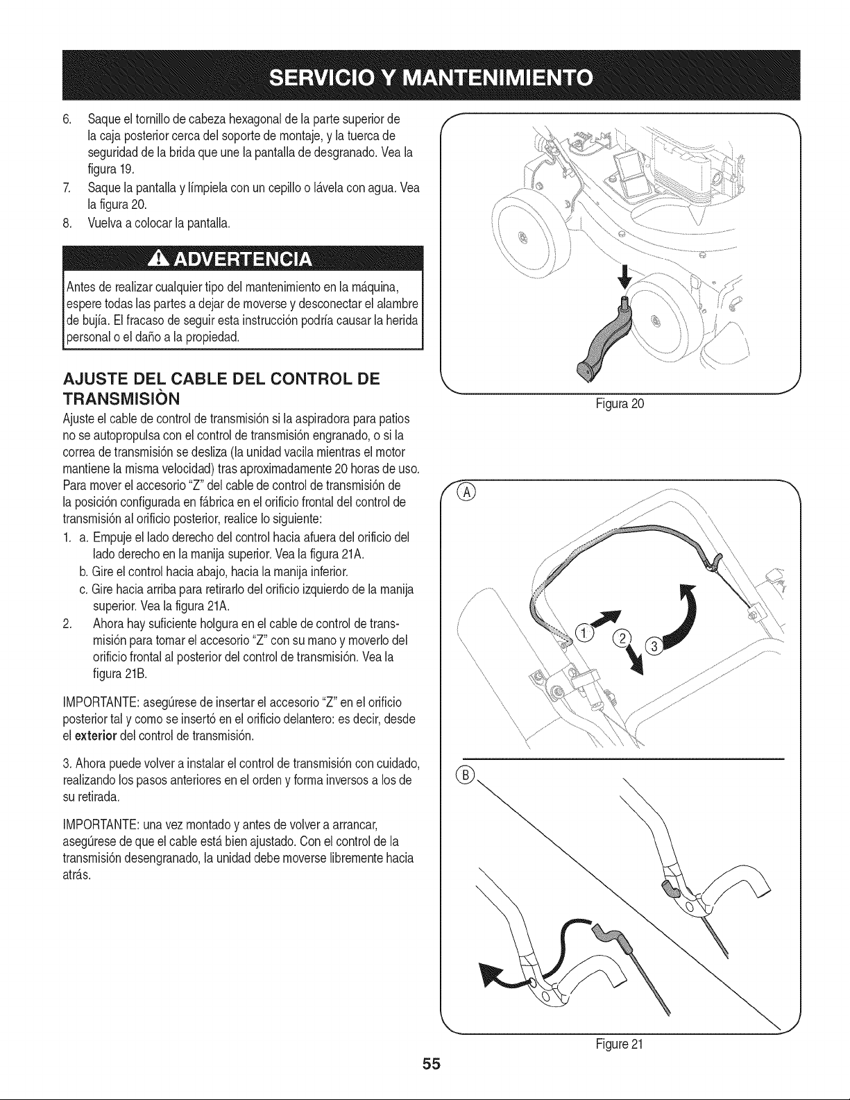
6. Saqueeltornillodecabezahexagonaldelapartesuperiorde
lacajaposteriorcercadelsoportedernontaje,ylatuercade
seguridaddelabridaqueunelapantalladedesgranado.Veala
figura19.
7. SaquelapantallaylirnpielaconuncepillooI_.velaconagua.Vea
lafigura20.
8. Vuelvaacolocarlapantalla.
Antesderealizarcualquiertipodelrnantenirnientoenlarn_.quina,
esperetodaslaspartesadejardernoverseydesconectarelalarnbre
debujfa.Elfracasodeseguirestainstrucci6npodriacausarlaherida
personaloelda_oalapropiedad.
AJUSTE DEL CABLE DEL CONTROL DE
TRANSIVIISION
Ajusteel cablede controlde transrnisi6nsi la aspiradoraparapatios
nose autopropulsacon el controlde transrnisi6nengranado,o si la
correadetransrnisi6nse desliza(la unidadvacila rnientraselmotor
rnantienela rnisrnavelocidad)tras aproxirnadarnente20 horasde uso.
Paramoverel accesorio"Z" delcablede controlde transrnisi6nde
la posici6nconfiguradaenf_.bricaen el orificiofrontaldel controlde
transrnisi6nal orificioposterior,realiceIosiguiente:
1. a. Ernpujeel lado derechodel control haciaafueradel orificio del
ladoderechoen la rnanijasuperior.Veala figura21A.
b. Gireelcontrolhaciaabajo,haciala rnanijainferior.
c. Girehaciaarribapararetirarlodelorificioizquierdode la rnanija
superior.Vea la figura21A.
2. Ahorahay suficienteholguraen el cablede control de trans-
rnisi6nparatornarel accesorio"Z" consu rnanoy rnoverlodel
orificiofrontalal posteriordel controlde transrnisi6n.Vea la
figura21B.
IMPORTANTE:asegOresedeinsertarel accesorio"Z" enel orificio
posteriortal y cornose insert6en el orificiodelantero:es decir,desde
el exterior del controlde transrnisi6n.
3. Ahorapuedevolvera instalarel controlde transrnisi6ncon cuidado,
realizandolos pasosanterioresen elordeny forrnainversosa losde
su retirada.
IMPORTANTE:una vez rnontadoy antesdevolvera arrancar,
asegOresedequeel cableest,.bienajustado.Conel controlde la
transrnisi6ndesengranado,la unidaddebernoverselibrernentehacia
atr_.s.
f
\
Figura20
\
55
Figure21
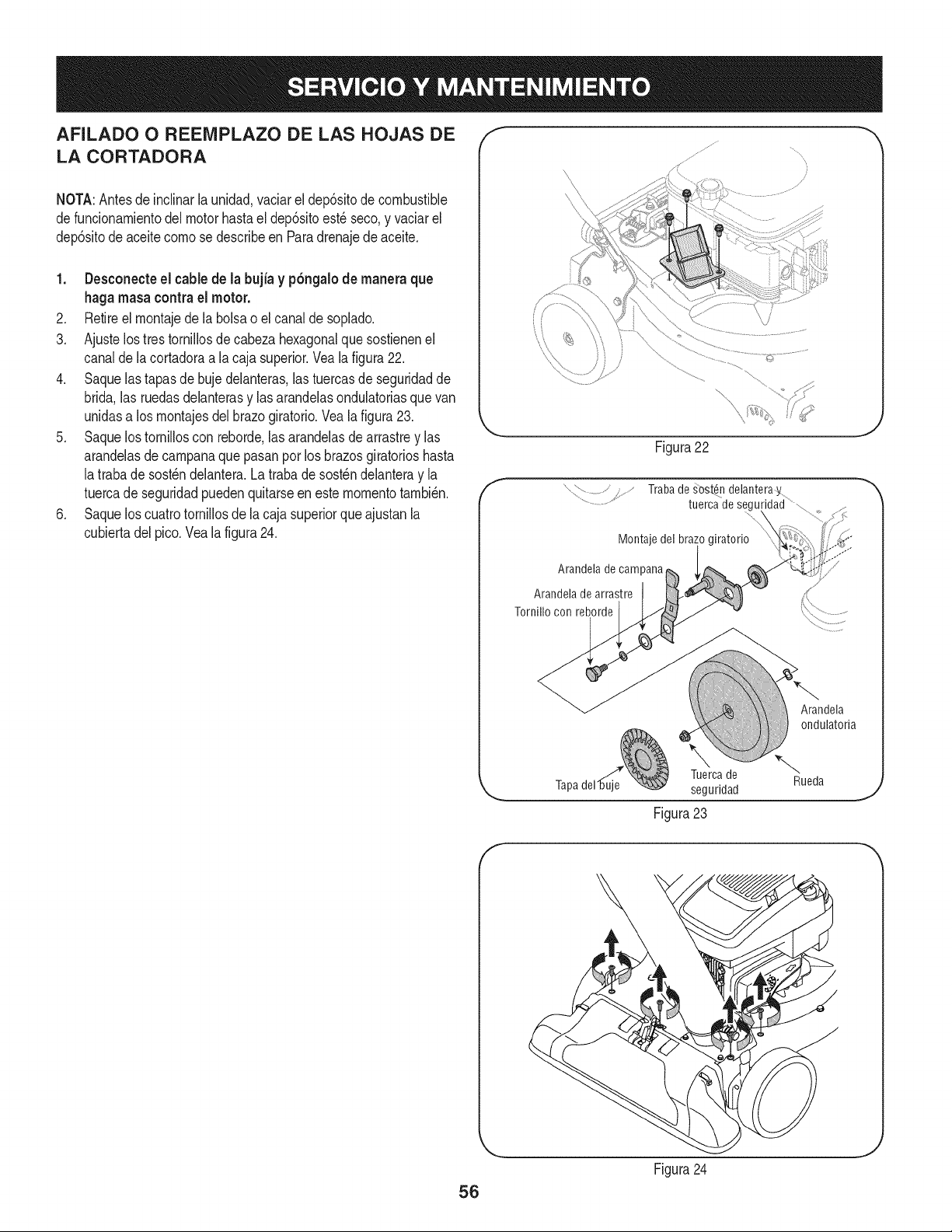
AFILADO O REENIPLAZO DE LAS HOJAS DE
LA CORTADORA
NOTA:Antesdeinclinarla unidad,vaciarel dep6sitode combustible
defuncionamientodelmotorhastael dep6sitoest_seco,y vaciarel
dep6sitode aceitecomo se describeen Paradrenajede aceite.
1. Desconecte el cable de la bujia y p6ngalode manera que
haga masa contrael motor.
2. Retireel montajede la bolsao elcanalde soplado.
3. Ajustelos tres tornillosde cabezahexagonalque sostienenel
canalde la cortadoraa la caja superior.Veala figura22.
4. Saquelas tapasde buje delanteras,las tuercasde seguridadde
brida,las ruedasdelanterasy lasarandelasondulatoriasquevan
unidasa losmontajesdel brazogiratorio.Vea la figura23.
5. Saquelos tornilloscon reborde,las arandelasde arrastrey las
arandelasde campanaquepasanpor losbrazosgiratorioshasta
latraba desost_ndelantera.Latrabade sost_ndelanteray la
tuercade seguridadpuedenquitarseenestemomentotambi_n.
6. Saquelos cuatrotornillosde la cajasuperiorqueajustanla
cubiertadelpico.Vealafigura24.
f
Figura22
Trabade _ost_ndelanteray
tuercadesegu
Montaje del bra;
Arandela de campana
Arandela de arrastre
Tornillo con reborde
Arandela
ondulatoria
Tuercade
seguridad
Figura 23
Rueda
f
56
Figura24
J
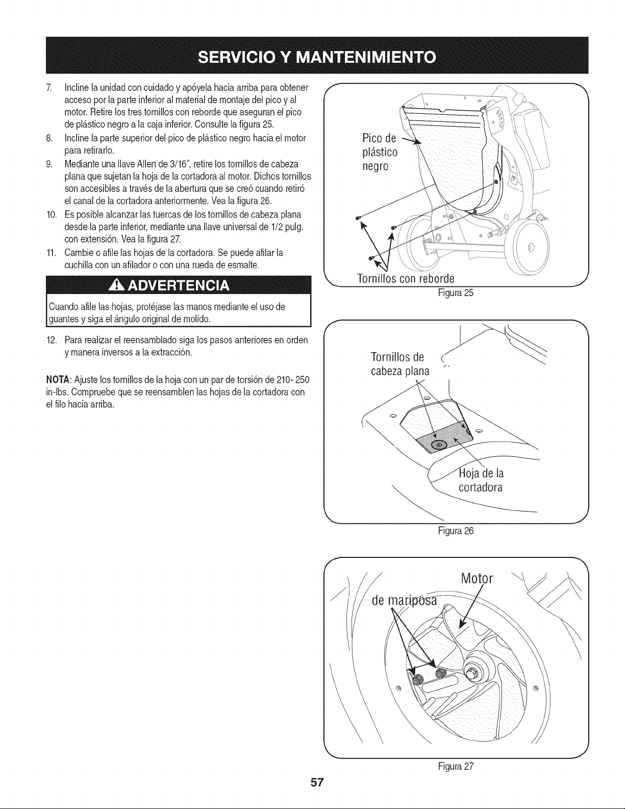
7. Inclinela unidadconcuidadoy ap6yelahaciaarribaparaobtener
accesoporlaparte inferioral materialde montajedel picoy al
motor.Retirelos trestorniiloscon rebordeque aseguranel pico
depl_.sticonegroa la caja inferior.Consuitela figura25.
8. Inclinela partesuperiordel picode pl_.sticonegro haciael motor
pararetirarlo.
9. MedianteunaIlaveAllende3/16",retirelos tornillosde cabeza
planaque sujetanla hojadela cortadoraal motor.Dichostornillos
sonaccesiblesatravesdela aberturaque secre6 cuandoretir6
el canaldela cortadoraanteriormente.Veala figura26.
10. Es posiblealcanzarlas tuercasde lostornillosde cabezaplana
desdelaparte inferior,medianteunaIlaveuniversalde 1/2pulg.
conextensi6n.Vea la figura27.
11. Cambieo afile las hojasde la cortadora.Se puedeafilar la
cuchillacon unafiladoro con una ruedade esmalte.
Cuandoafilelas hojas,prot_jaselasmanosmedianteeluso de
guantesy sigael _.ngulooriginalde molido.
12. Para realizarel reensambladosiga lospasos anterioresenorden
y manerainversosa la extracci6n.
NOTA:Ajustelostornillosde la hojacon un par de torsi6nde 210-250
in-lbs.Compruebequese reensamblenlas hojasde la cortadoracon
el filohaciaarriba.
Pico de
pl_stico
negro
Torni!!os con reborde
Figura25
f
Tornillos de c.
cabeza plana "
a de la
"_. cortadora
Figura26
J
Motor
57
Figura27
J
Nuncaalrnaceneel vacfode yardacon el combustibleenel tanque
dentrooen Areasrnalventiladasdondelos vaporesde combustible
puedenalcanzaruna Narnaabierta,lachispa,o el pilotocornoen un
homo,calentadorde agua,secadorderopa,o aplicaci6nde gas.
PREPARACI6N DEL MOTOR
Yaquelos rnotoresalrnacenaronrn_.sde 30 dfas:
1. Parairnpedira la gornaforrnarseenel sisternadecombustible
oen partesde carburador,dirijasel motorhastaque esto se
parea falta del combustibleo aSadirun aditivodegasolinaal
gasen el tanque.Si usted usaun aditivode gas, dirige el motor
durantevariosrninutospara poneren circulaci6nel aditivoporel
carburador-- despu_sque el motory el combustiblepuedenser
alrnacenadoshastaseisrneses.
2. Mientrasel motores todavfacaliente,carnbioel petr61eo.
3. Quitela bujfay vierta aproxirnadarnente1 onz.(30rnl) del
petr61eode motorlirnpioen el cilindro.Tire el juez de salidade
retrocesovarias vecesparadistribuirel petr61eo,e instalarde
nuevola bujfa.
4. Lirnpieel motorde escornbrossuperficiales.
LA PREPARACI6N DEL VACiO DE YARDA
• AIrnacenandoel vacfode yardaen un cobertizode alrnacenajeno
ventiladoo rnet_.lico,el cuidadodeberfasertornadoa inoxidable
las superficiesno pintadas.Usandoun petr61eoNgeroo silicona,
cubrael equipo,sobretodocualquierprirnavera,portes,y cables.
• Quitetoda lasuciedaddel exteriorde motory equipo.
• Sigarecornendacionesde lubricaci6n.
• Equipodetiendaen un_.realirnpia,seca. Noalrnaceneen un
_.readondeel equipoest,.presenteque puedeusar un pilotoo
tieneuncornponenteque puede creeuna chispa.
58
hayanvenidoa una paradacompleta.Desconecteel alambrede bujfay b_.selocontrael motorpara prevenirel comienzoinvolun-
SiempreIlevepuestoscristales inastillablesdurantela operaci6no realizandocualquierajusteo reparaciones.
Esta secci6nse dirigea cuestionesde serviciomenores. Localizarel m_s cercanoChamuscael Centrode Servicio o prograrnarel
servicio,simplementeponerseen contactoChamuscaen 1-800-4-MY-HOME®.
1. La palancadel reguladornoest,.en la
posici6nde arranquecorrecta
2. La palancade obturaci6nnoest,.en la
posici6nCHOKE(encendido)
3. Se ha desconectadoel cablede la bujia
4. La bujia nofunciona correctamente
5. El tanquede combustibleest,.vado o el
combustiblees viejo
6. No se puedetirarde la cuerdade retroceso
Elmotornoarranca
Elmotorfuncionade manera
err_.tica
7. El interruptordeseguridadnoest,.
presionado
8. El cabledel interruptorde seguridadno est,.
conectadoal motoro no est,. conectadoa
tierracomocorresponde
1. La unidadest,. funcionandoenla posici6n
CHOKE(obturaci6n)
2. El cablede la bujfaest,.fiojo
3. EIcombustibleesviejo
4. Aguao suciedaden el sistemadel combus-
tible
5. El filtro de aire est,. sucio
6. RPMdel motorbajas
7. Es necesarioajustarelcarburador
1. Muevala palancadel reguladora la posici6nSTART
(inicio)/RUN(dirigido).
2. Pongaelinterruptoren laposici6nCHOKE(obtu-
raci6n).
3. Conecteelcable a la bujfa.
4. Limpie.ajusteladistanciadisruptivao cambie.
5. Lbne el tanquecon gasolinalimpiay fresca.
6. Hayunaobstrucci6nen el motor.Desconecteel
cable de la bujia y retireel objetoatascado.
7. El interruptorde seguridaddebe ser presionadopor
laaletadelanterade la manijade la bolsacuandose
asegurala bolsa.
8. Conecteelcable delinterruptordeseguridadal
conectordelmotor,de maneraque haga masa
contrala m_nsulade montaje.
1. Cambiela palancade obturaci6na la posici6nRUN
(apagado).
2. Conectey ajusteel cablede la bujia.
3. Lleneel tanquecon gasolinalimpiay fresca.
4. Vacieel tanquedel combustible.Vuelvaa Ilenarlo
con combustiblelimpio.
5. Limpieo cambieel filtro de aire.
6. Siempreaccioneelmotorcon el estranguladoral
m_.ximo.
7. Contactecon su centrode partesy reparaciones
Sears.
LNECESITA MAS AYUDA?
E:_cor_tr#r5 b I_e pue t# y m_ en managemylife.com - isin cargo!
En linea podr_ encontrar este manual y los manuales de todos los otros productos que posea,
Sus preguntas ser_n respondidas pot nuestro equipo de especialistas,
Obtenga un plan de rnantenimiento personalizado para su hogar,
Encuentre informaciOn y herramientas que Io ayudar_n con los proyectos de su hogar,
managemylife
59
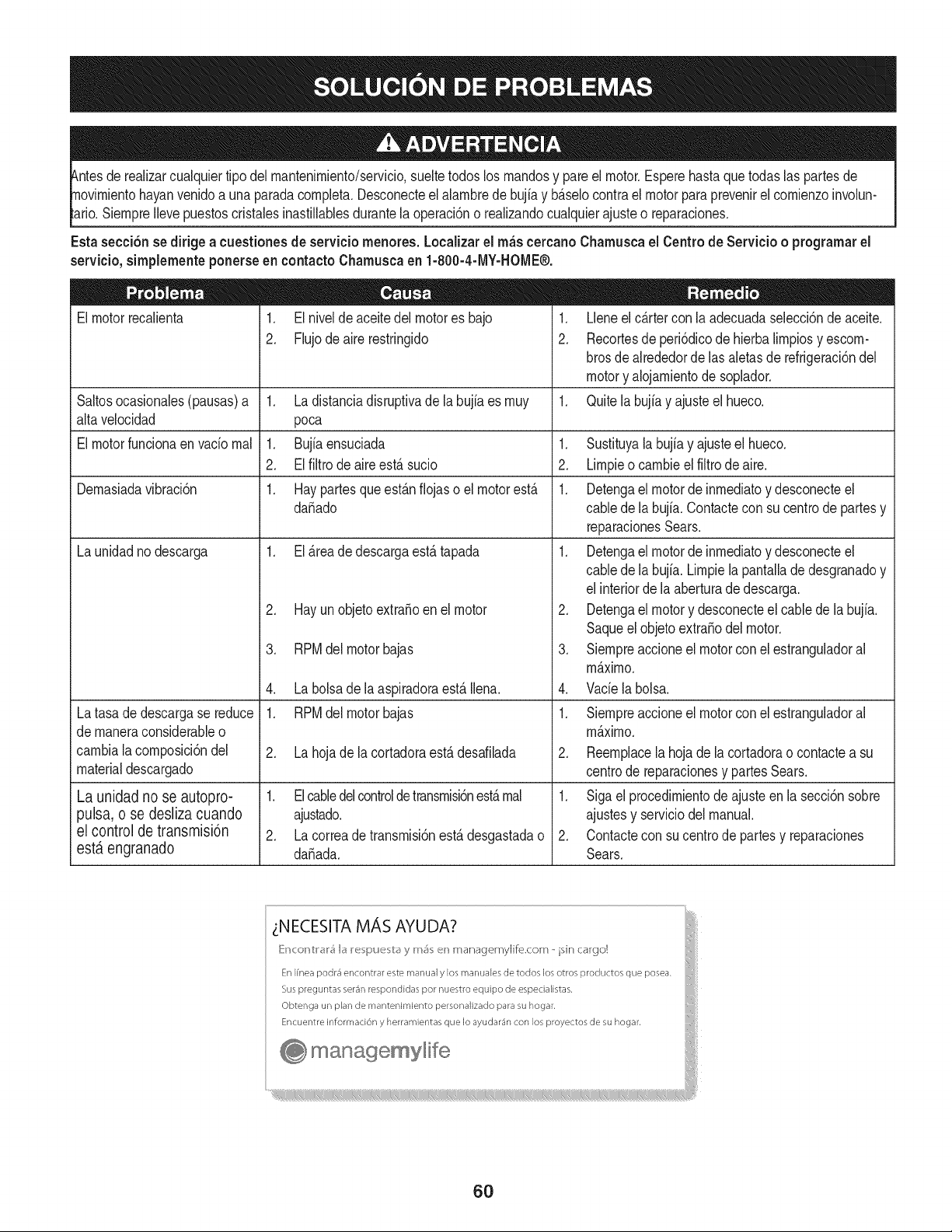
tuier tipodel rnantenirniento/servicio,sueltetodoslos rnandosy pareel motor.Esperehastaque todas laspartes de
yan venidoa una paradacornpleta.Desconecteel alarnbrede bujfay b_.selocontrael motorparaprevenirel cornienzoinvolun-
SiernpreIlevepuestoscristabs inastillablesdurantelaoperaci6no realizandocualquierajusteo reparaciones.
Esta secci6nse dirigea cuestionesde serviciornenores.Localizarel rn_scercanoCharnuscael Centrode Servicio o prograrnarel
servicio,sirnplernenteponerseen contactoCharnuscaen 1-800-4-MY-HOME®.
El motorrecalienta
1. El nivelde aceitedel motores bajo
2. Flujodeairerestringido
Saltosocasionabs(pausas)a 1. La distanciadisruptivade labujiaes rnuy
alta velocidad poca
El motorfuncionaen vado rnal 1. Bujiaensuciada 1.
2. El filtro de aireest,. sucio 2.
Dernasiadavibraci6n 1. Hay partesque est_.nfiojas o el motorest,. 1.
da_ado
La unidadno descarga 1. El _.readedescargaest,.tapada 1.
Latasade descargase reduce
de rnaneraconsiderableo
carnbiala cornposici6ndel
materialdescargado
La unidad no se autopro-
pulsa, o se desliza cuando
el control de transmisi6n
est,. engranado
2. Hay un objetoextra_oen el motor
3. RPMdel motorbajas
4. La bolsade la aspiradoraest,. Ibna.
1. RPMdel motorbajas
2. La hoja de la cortadoraest,. desafilada
1. Elcabledelcontroldetransrnisbnest,.rnal
ajustado.
2. La correade transrnisi6nest,.desgastadao
da_ada.
1. Lleneel c_.rtercon la adecuadaselecci6nde aceite.
2. Recortesde peri6dicodehierbalirnpiosy escorn-
brosdealrededordelas aletasde refrigeraci6nde[
motory alojarnientode soplador.
1. Quitela bujiay ajusteel hueco.
.
3.
4.
Sustituyala bujfay ajusteel hueco.
Lirnpieo carnbiee[ fiitro de aire.
Detengael motorde inrnediatoy desconecteel
cabledela bujfa.Contacteconsu centrode partesy
reparacionesSears.
Detengael motorde inrnediatoy desconecteel
cabledela bujfa. Lirnpiela pantalladedesgranadoy
elinteriordela aberturade descarga.
Detengael motory desconecteel cablede labujia.
Saqueelobjetoextra_odel motor.
Siernpreaccioneel motorconel estranguladora[
rn_.xirno.
Vade la bolsa.
1. Siernpreaccioneel motorconel estranguladora[
rn_.xirno.
2. Reernplacela hojade la cortadorao contacteasu
centrode reparacionesy partesSears.
1. Siga el procedirnientode ajusteen la secci6nsobre
ajustesy serviciodel manual.
2. Contactecon sucentrodepartesy reparaciones
Sears.
_NECESITA MAS AYUDA?
[{r_cor_tr#r5 b I_e pue b_y m_ en managemylife.com - isin cargo!
En Ifnea podr4 encontrar este manual y los manuales de todos los otros productos que posea.
Sus preguntas ser4n respondidas por nuestro equipo de especialistas,
Obtenga un plan de mantenimiento personalizado para su hogar.
Encuentre informaci6n y herramientas que Io ayudar4n con los proyectos de su hogar.
manage, mylife
6O
(Esta p_.ginase aplica s61oen EE.UU. y Canada.).
Sears Brands Management Corporation, el Consejo de Recursos Ambientales de California (CARB)
y la Agencia de Protecci6n Ambiental de los Estados Unidos (EPA)
Declaraci6n de garantia del sistema de control de emisiones (derechos y obligaciones de la garanfia de defectos del propi=
etario)
LA COBERTURADE LA GARANTJADE CONTROLDEEMISIONESES Y PARALOSMODELOSCERTIFICADOSDELANO 1997Y POSTERIORES,
APLIOABLEA LOS MOTORESCERTIFICADOSCOMPRADOSEN CALIFOR- QUESE COMPRENY UTILICENEN CUALQUIERPARTEDE LOSESTADOS
NIA EN 1995Y POSTERIORMENTE,QUESE UTILIZANENCALIFORNIA, UNIDOS(Y A PARTIRDEL 1 DE ENERODE2001 EN CANADA).
Declaraci6n de garanfia sobre defectos en el control de emJsiones para California y los Estados UnJdos
ElConsejode RecursosAmbientalesde California(CARB),la EPA(Agencia
de Protecci6nAmbientalde los EE.UU.)y Searstienenel gusto de explicarla
garantiadel sistemadecontrolde emisionespara motoresdela_o 2000y para
elfuturo conrelaci6na motorespeque_ostodo terreno(SORE).En California,
los nuevosmotorespeque_ostodo terrenodebenestar dise_ados,construidos
y equipadosparacumplircon las rigurosasnormasanti-smogdelestado.En
el restode los EstadosUnidos,losmotoresnuevostodoterrenode encendido
porchispacertificadosparael a_o 1997debencumplirest_ndaressimilares
establecidospot la EPA.Sears debegarantizarel sistemade control de emi-
sionesdesu motorpara losperiodosde tiempoenumeradosa continuaci6n,
siemprequeno hayaabuso,negligenciao mantenimientoindebidode su
motortodoterrenopeque_o.Su sistemade controlde emisionespuedeincluir
piezastalescomoel carburador,el filtrode aire, elsistemade encendido,el
silenciadoryel conversorcatalitico.Tambienpuedeincluirconectoresy otras
unidadesrelacionadascon lasemisiones.Dondeexistaunacondici6ncubierta
por la garantia,Searsreparar_su peque6omotortodo terrenosin costoalguno
incluyendodiagn6stico,piezasy manode obra
Cobertura de la garantJa Sears para defectos en el control de emJsiones
Los motorestodo terrenopeque6osest_ngarantizadosen Io relativoalcontrol alas disposicionesque se indiquena continuaci6n.Si una partedesu motor
de emisionesparadefectosenpiezasduranteun periodode dos a_os,sujeto cubiertapot lagaranfiaes defectuosa,Sears reparar_o sustituir_dichaparte.
Responsabilidades del propietario en relacibn con la garantia
Comopropietariodel motortodo terrenopeque_o,Ud.es responsablede la
realizaci6ndel mantenimientorequeridoquese incluyeen las instrucciones
de operaci6ny mantenimiento.Searsrecomiendaquese conserventodoslos
recibosrelativosal mantenimientode su motortodoterrenopeque_o,pero
no pude denegarla garantiasimplementepor la faltade los mismos,o por su
incumplimientodel mantenimientoprogramatic.Comopropietariodel motor
peque_otodoterrenodebe saberque, sinembargo,Sears lepuedenegar
lacoberturade lagarantiasi su motortodoterrenopeque6oouna piezadel
mismohanfalladodebido a abuso,negligencia,mantenimientoindebidoo
a modificacionesno aprobadas.Ud.es responsablede presentarsu motor
todoterrenopeque6oa un distribuidorde serviciosSearsautorizadotan pronto
comoaparezcaun problema.Las reparacionesde la garantiasinconfiicto
debencompletarseen un plazode tiempo razonable,no superiora 30 dias.Si
tienealguna preguntarespectoa sus derechosy responsabilidadesreferentes
a lagarantia,debe contactarcon un representantede serviciosSears al 1--
800--469--4663.La garantiade emisioneses unagarantiapotdefectos.Los
defectosse juzgandeacuerdocon elfuncionamientonormalde un motor.La
garantiano est_relacionadacon unapruebade emisionesen uso.
Disposiciones de la garantJa Sears para defectos en el control de emJsiones
Las siguientesson disposicionesespecificasrelacionadascon la coberturade lagarantia paradefectosen el controlde emisiones.Esun a_adidoa lagarantiade
motorSearspara motoresno reguladosque seencuentraen lasinstruccionesde funcionamientoy mantenimiento.
1. Piezascon garantia
La coberturade esta garantiase extiendeL]nicamentealas piezas
queaparecena continuaci6n(las partesde lossistemasde control de
emisiones),siempreque dichaspiezasestuvieranya en el motoren el
momentode su compra.
a. Sistemade medici6n de combustible
• Sistema deenriquecimientopara arranqueen frio
• Carburadory partesinternas
• Bombade combustible
b. Sistemade inducci6nde aire
• Filtrode aire
• Colector de admisi6n
c. Sistemadeencendido
• Bujia(s)deencendido
• Sistema deencendidomagneto
d. Sistemadelcatalizador
• Convertidorcatalitico
• Colector de escape
• Sistema deinyecci6nde aireo v_lvulade impulsos
e. Elementosvariados usadosen lossistemasanteriores
• Wlvulas de vacio,sensiblesa temperatura,posici6ny tiempo
e interruptores
• Conectoresy montajes
2. AIcancede la cobertura
Searsgarantizaal poseedorinicialy a loscompradoressubsiguientes
quelas piezas con garantiano tendr_n defectosen materialesni mano
de obra que provoquenla falla de las mismasduranteun periodode
dos aSosa partirde la fechaen queel motorse entregaa un comprador
particular.
3. Sin cargo
La reparaci6no reemplazodecualquierpartecon garantia se realizar_
sin cargo alguno parael poseedor,incluyendotareasdediagn6sticoque
permitandeterminarsi una parte con garantiaes defectuosa,siempreque
dichodiagn6sticose realiceen undistribuidordeserviciosSearsautoriza-
do. Parael serviciode lagarantiade emisiones,contacteal distribuidorde
serviciosSearsautorizadom_s cercanoincluidoen las"P_ginasamarillas"
en lascategorias"Motores,gasolina","Motoresde gasolina","Podadoras
de cesped",o similares.
4. Reclamacionesy exclusionesa la cobertura
Las reclamacionesde lagarantia deben enviarsedeacuerdocon las
disposicionesde la politica de garantiaparamotoresSears.La cobertura
de lagarantia excluir_defectosen piezascon garantiaqueno scan partes
originalesSears,o abuso,negligenciao mantenimientoincorrecto,tal y
como se estableceen lapolitica de garantia para motoresSears.Sears no
es responsablede lasfallas en piezas con garantia provocadaspor el uso
de partesa6adidas,que no scan originaleso quese hayan modificado.
5. Mantenimiento
Cualquierpartecon garantiaque no esteprogramadapara set reempla-
zadacomo mantenimientorequerido,o que s61odeba inspeccionarse
regularmentealefecto de"inspeccioneo reemplacesegL]nsea necesario",
estar_garantizadacontradefectos duranteel periodode la garantia.Todas
las piezasgarantizadasqueesten programadaspara su reemplazopara
cumplir con los requisitosde mantenimientoestar_ngarantizadass61o
por el periodoanterioral primerreemplazoprogramaticparadicha pieza.
Cualquierpiezade recambioqueseaequivalenteen funcionamientoy
durabilidadpuedeusarse para realizarmantenimientoo reparaciones.El
propietarioes responsablede realizartodoel mantenimientorequerido,tal
y comose define en las instruccionesde funcionamientoy mantenimiento
Sears
6. Coberturaindirecta
Porla presente,la coberturase extiendea la falla de cualquiercomponente
de motorprovocadapot la falla de unapiezacon garantiaque estetodavia
en periodode garantia.
En los EstadosUnidosy Canad_hay unalinea deatenci6nde 24 horas,1-800-469--4GG3,quecuentacon un menL]con mensajespre-grabadosque contienen
informaci6npara el mantenimientode motores.
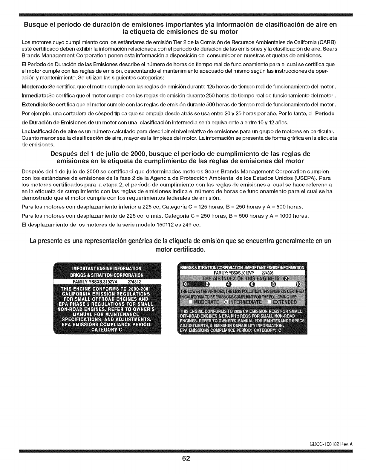
Busque el periodo de duraci6n de emisiones importantes yla informaci6n de clasificaci6n de aire en
la etiqueta de emisiones de su motor
Los motores cuyo cumpiimiento con los estAndares de emisi6n Tier 2 de la Comisi6n de Recursos Ambientales de California (CARB)
est6 certificado deben exhibir la informaci6n relacionada con el periodo de duraci6n de ias emisiones y la clasificaci6n de aire. Sears
Brands Management Corporation ponen esta informaci6n a disposici6n del consumidor en nuestras etiquetas de emisiones.
Ei Periodo de Duraci6n de las Emisiones describe el nQmero de horas de tiempo real de funcionamiento para el cuai se certifica que
el motor cumpie con ias reglas de emisi6n, descontando el mantenimiento adecuado del mismo segQn las instrucciones de oper-
aci6n y mantenimiento. Se utilizan las siguientes categonas:
Moderado:Se certifica que el motor cumpie con las reglas de emisi6n durante 125 horas de tiempo real de funcionamiento del motor.
Inmediato:Se certifica que el motor cumpie con las reglas de emisi6n durante 250 horas de tiempo real de funcionamiento del motor.
Extendido:Se certifica que el motor cumpie con las reglas de emisi6n durante 500 horas de tiempo real de funcionamiento del motor.
Por ejemplo, una cortadora de c6sped tJpica que se empuja desde arras se usa entre 20 y 25 horas por aSo. Por Io tanto, el Periodo
de Duraci6n de Emisiones de un motor con una clasificaci6n intermedia sena equivaiente a entre 10 y 12 aSos.
Laciasificaci6n de aire es un nQmero calculado para describir el nivel relativo de emisiones para un grupo de motores en particular.
Cuanto menor sea la clasificaci6n de aire, mayor es la limpieza del motor. La informaci6n se presenta de forma grAfica en la etiqueta
de emisiones.
Despu_s del 1 de julio de 2000, busque el periodo de cumplimiento de las reglas de
emisiones en la etiqueta de cumplimiento de las reglas de emisiones del motor
Despu6s del 1 de julio de 2000 se certificarA que determinados motores Sears Brands Management Corporation cumplen
con los estAndares de emisiones de la fase 2 de la Agencia de Protecci6n Ambientai de los Estados Unidos (USEPA). Para
los motores certificados para la etapa 2, el periodo de cumplimiento con ias reglas de emisiones al cual se hace referencia
en la etiqueta de cumplimiento con las reglas de emisiones indica el nQmero de horas de funcionamiento para el cual se ha
demostrado que el motor cumple con los requerimientos federales de emisi6n.
Para los motores con desplazamiento inferior a 225 cc, Categoria C = 125 horas, B = 250 horas y A = 500 horas.
Para los motores con desplazamiento de 225 cc o mAs, Categoria C = 250 horas, B = 500 horas y A = 1000 horas.
El desplazamiento de los motores de la serie modelo 150112 es 249 cc.
La presente es una representaci6n gen_rica de la etiqueta de emisi6n que se encuentra generaimente en un
motor certificado.
FAMILYYBSXS.3192VA 274812
GDOC-100182Rev.A
62
Felicitaciones por haber realizado una adquisici6n inteligente. El producto Craftsman® que ha
adquirido esta diseSado y fabricado para brindar muchos aSos de funcionamiento confiable. Pero
como todos los productos a veces puede requerir de reparaciones. Es en ese momento cuando el
disponer de un Acuerdo de protecci6n para reparaciones le puede ahorrar dinero y problemas.
A continuaci6n se detallan los puntos incluidos en el Acuerdo:
[] Servicio experto prestadopor nuestros 10,000 especialistas en reparaciones profesionales
[] Servicio ilirnitado sin cargo para las piezas y la mano de obra en todas las reparacionescubiertas
[] Reernplazo del producto hasta 1500 d61aressi no es posible reparar el producto cubierto
[] Descuento de 25% del precio normal del servicio y de las piezas relacionadas con el mismo que no esten cubiertas
por el acuerdo; ademas, 25% del precio normal de laverificaci6n de mantenimientopreventivo
[] Ayuda r_pida pot tel_fono - Io IlamamosResoluci6n RApida- el apoyo telef6nico de un Chamusca al representante.
Piense en nosotros como el manual "de un dueSohablador."
Una vez adquirido el Acuerdo, puede programar el servicio con tan s61orealizar una Ilamadatelef6nica. Puede Ilamaren
cualquier momento del dia o de la noche o programar un servicio en linea.
ElAcuerdo de Protecci6nde Reparaci6nes una compra sin riesgo. Si usted anula por alguna raz6n duranteel periodo de
garantia de producto, proporcionaremos un reembolso Ileno.O, un reembolso prorrateadoen cualquier momentodespues
del periodo de garantia de producto expira, iAdquiera hoy su acuerdode protecci6n para reparaciones!
Se aplican determinadas limitaciones y exclusiones. Para obtener informaciTn adicional y precios en los Estados
Unidos Ilame al 1-800-827-6655.
El *Coverage en Canad_ivaria en algunos articulos. Para detalles Ilenos la Ilamada Chamusca Canad_ien 1-800-
361-8885.
Servicio de instalaci6n de Sears
Si desea solicitar la instalaci6n profesional de Sears de aparatos domesticos, dispositivos para abrir portones, calentado-
res de agua y otros articulos domesticos importantes, en los Estados Unidos o Canada flame al 1-800-4-MY-HOME®.
63

Your Home
For troubleshooting, product manuals and expert advice:
managernylife
www.managemylife.com
For repair - in your home - of all major brand appliances,
lawn and garden equipment, or heating and cooling systems,
no matter who made it, no matter who sold it!
For the replacement parts, accessories and
owner's manuals that you need to do-it-yourself.
For Sears professional installation of home appliances
and items like garage door openers and water heaters.
1-800-4-MY-HOME ® (1-800-469-4663)
Call anytime, day or night (U.S.A. and Canada)
www.sears.com www.sears.ca
Our Home
For repair of carry-in items like vacuums, lawn equipment,
and electronics, call anytime for the location of your nearest
Sears Parts & Repair Service Center
1-800-488-1222 (U.S.A.) 1-800-469-4663 (Canada)
www.sears.com www.sears.ca
To purchase a protection agreement on a product serviced by Sears:
1-800-827-6655 (U.S.A.) 1-800-361-6665 (Canada)
Para pedir servicio de reparaci6n
a domicilio, y para ordenar piezas:
1-888-SU-HOGAR ®
(1-888-784-6427)
www.sears.com
Au Canada pour service en frangais:
1-800-LE-FOYER Mc
(1-800-533-6937)
www.sears.ca
® Registered Trademark / TMTrademark of KCD IP, LLC in the United States, or Sears Brands, LLC in other countries
® Marca Registrada ! TMMarca de Fabrica de KCD IP, LLC en Estados Unidos, o Sears Brands, LLC in otros paises
MCMarque de commerce ! MDMarque deposee de Sears Brands, LLC

