OWNER'S MANUAL
CAUTION
RISKOFELECTRICSHOCK
\ DONOTOPEN
CAUTION: TO REDUCE THE RISK OF
ELECTRIC SHOCK, DO NOT REMOVE
COVER (OR BACK). NO USER-SERVICEABLE
PARTS INSIDE. REFER SERVICING TO
QUALIFIED SERVICE PERSONNEL.
• Explanation of Graphical Symbols
The lightning flash with anowhead symbol, within all
equilateral triangle, is intended to alert you to the
presence of uninsulated "dangerous voltage" within
the product's enclosure that may be of sufficient
magnitude to constitute a risk of electric shock to
persons
The exclamation point within an equilateral triangle
is intended to alert you to the presence ofilnponant
operating and maintenance (servicing) instructions in
the literature accompanying the applimlce
1 Read Instructions All the safety and operating instructions
should be read before the product is operated.
2 Retain Instructions The safety and operating instructions
should be retained for ffltttre reference.
3 Heed "V\_arnings All warnings on the product and in the
operating instructions should be adhered to.
4 Follow Instructions All operating and use instructions
should be followed.
5 Cleaning Unplug this product from the wall outlet before
cleaning. Do not use liquid cleaners or aerosol cleaners.
6 Attachments Do not use attaclnnents not recomlnended by
the product manufacturer as they may cause hazards.
7 Water and Moisture Do not use this product near water
lbr exanlple, near a bath tub. wash bowl kitchen sink, or
laundry tub: in a wet basement: or near a swinmling pool:
and the like.
8 Accessories Do not place this product on an unstable cart,
stand, tripod, bracket, or table. The product may fall
cansing serious il_iury to a child or adult, and serious
dan_age to the product. Use only with a cart, stand, tripod,
bracket, or table reconnnended by the manufacturer, or sold
with the product. Any motmting of the product should
lbllow the manufi_cturer's instructions, and should use a
mounting accessory recommended by the manu±'acmrer.
9 A prodnct and cart combination should be moved with care.
Quick stops, excessive lbrce, and nneven surfaces may
cause the prodnct and cart combination to
overturll.
10 Ventilation Slots and openings in the cabinet are provided
for ventilation and to ensure reliable operation of the
product and to protect it from overheating, and these
openings must not be blocked or covered. The openings
should never be blocked by placing the product on a bed,
sofa, rug, or other similar surfi_ce. This product should not
be placed in a built-in installation such as a bookcase or rack
unless proper ventilation is provided or the manu*hcmrer's
instructions have been adhered to.
11 Power Sources This product shouldbe operated only from
the type of power sonrce indicated on the marking label. If
)<_uare not sure of the type of power supply to your home.
consult yoar prodnct dealer or local power company. For
prodncts intended to operate from batte D"power, or other
sources, refer to the operating instructions.
12 Grounding or Polarization This product may be equipped
with a polarized alternating current line plug (a plug having
one blade wider than the other). This plug will fit into the
power outlet only one way. This is a safety feature. If you
are tmable to insert the plug fully into the outlet, try
reversing the plug. If the plug should still fail to fit, contact
3_ur electrician to replace yottr obsolete outlet. Do not
defeat the safety purpose of the polarized plug.
13 Power-Cord Protection Power-supply cords should be
routed so that they are not likely to be walked on or pinched
by items placed upon or against them, paying particular
attention to cords at plugs, convenience receptacles, and the
point where they exit froln the product.
14 Lightning For added protection for this product dnring a
lighming storm, or when it is left unattended and unused for
long periods of time. unplug it from the wall outlet and
disconnect the antenna or cable system. This will prevent
damage to the product due to lighming and power-line
surges.
15 Power Lines An outside antenna system should not be
located in the vicinity of overhead power lines or other
electric light or power circuits, or where it can fall into such
power lines or circuits. \_l_en installing an outside ante_ma
system, extreme care should be taken to keep from touching
such power lines or circuits as contact with them might be
*;atal.
16 Overloading Do not overload wall outlets, extension
cords, or integral convenience receptacles as this can result
in a risk of fire or electric shock.
17 Object and Liqnid Entry Never push objects of any"kind
into this product through openings as they may touch
dangerous voltage poims or short-out parts that could result
in a fire or electric shock. Never spill liquid of any kind on
the product.
18 Servicing Do not attempt to service this product yonrself
as opening or removing covers may expose you to
dangerous voltage or other hazards. Refer all servicing to
qualified selwice personnel.
19 Damage Requiring Service Unplug this product from the
wall outlet and refer servicing to qnalified service persmmel
under the following conditions:
a) When the power-supply cord or plug is damaged,
b) If liquid has been spilled, or ot!iects have ±;alleninto the
product,
c) If the product has been exposed to rain or water,
2O
21
22
d) If the product does not operate nom'lally by following
the operating instructions. Adjust only those controls
that are covered by the operating instructions as an
improper ac[iusnnent of other controls may result in
damage and will often require extensive work by a
qualified technician to restore the product to its normal
operation.
e) If the product has been dropped or danlaged in any
wa?\ and
f) When the product exhibits a distinct change in
peribnnance - this indicates a need for service.
Replacemem Parts When replacement parts are required.
be sure the service teclmician has used replacement parts
specified by the manufacturer or have the same
characteristics as the original part. Unauthorized
substitutions 1nay result in fire, electric shock, or other
hazards.
Safety Check Upon completion of any service or repairs to
this product, ask the service technician to perform safety
checks to deterlrfine that the product is in proper operating
condition.
"v\M1or Ceiling Mounting The unit should be mounted
to a wall or ceiling only as reconmlended by the
manufacturer.
23 Heat The product should be situated away _om heat
sources such as radiators heat registers, stoxes or other
products (including anlplifiers) that produce heat.
24
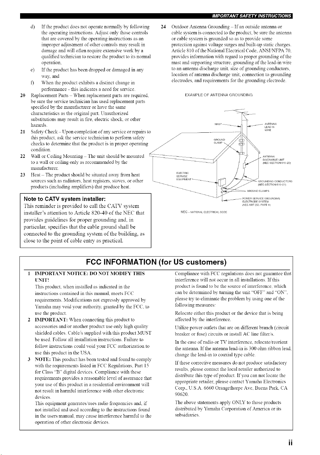
Outdoor Antenna Grounding If an outside antenna or
cable system is connected to the producL be sure the antenna
or cable system is grounded so as to provide some
protection against voltage surges and built-up static charges.
Article 810 of the National Electrical Code. ANSI_FPA 70,
provides in±\mnation with regard to proper grounding of the
mast and supporting structure, grounding of the lead-in wire
to an anteana discharge unit. size of gounding conductors,
location of antelma discharge unit, connection to grounding
electrodes, and requirements for the grounding electrode.
EXAMPLE OF ANTENNA GROUNDING
Note to CATV system installer:
This reminder is provided to call the CATV system
installer's attention to Article 820-40 of the NEC that
provides guidelines for proper grounding and, in
particular, specifies that the cable ground shall be
connected to the grounding system of the building, as
close to the point of cable entry as practical.
NEC NATIONAL ELECTRICALCODE
FCC INFORMATION (for US customers)
1 IMPORTANT NOTI(E: DO NOT MODIFY THIS
UNIT!
This product, when installed as indicated in the
instructions contained in this manual, meets FCC
requirements. Modifications not expressly approved by
Yanlaha may void your anthorit3: granted by the FCC, to
use the product.
IMPORTANT: _X&enconnecting this product to
accessories and/or another product use only high quality
shielded cables. Cableis supplied with this product MUST
be used. Follow all installation instructions. Failttre to
follow instructions could void your FCC anthorization to
use this product in the USA.
NOTE: This product has been tested and found to comply
with the requirements listed in FCC Regulations. Part 15
for Class "B" digital devices. Compliance with these
requirements provides a reasonable level of assurance that
yore- use of this product in a residential environment will
not result in harmful interference with other electronic
devices.
This equipment generates/uses radio frequencies and, if
not installed and used according to the instructions found
in the users manual, may cause interference harntful to the
operation of other electronic devices.
Compliance with FCC regulations does not guarantee that
interference will not occur in all installations. If this
product is funnd to be the source of interference, which
can be determined by ttmting the unit "OFF" and "ON",
please tD" to eliminate the problem by using one of the
following measures:
Relocate either this product or the device that is being
affected by the interference.
Utilize power outlets that are on different branch (circuit
breaker or fuse) circuits or install AC line filteris.
In the case of radio or TV interference, relocate reorient
the antenna. If the antenna lead-in is 300 olnn ribbon lead.
change the lead-in to coaxial type cable.
If these corrective measures do not produce satisI;autoD"
results, please contact the local retailer authorized to
distribute this type of product. If you can not locate the
appropriate retailer, please contact Yamaha Electronics
Corp.. U.S.A. 6660 Orangethorpe Ave. Buena Park. CA
90620.
The above statements apply ONLY to those products
distributed by Yamaha Corporation of America or its
subsidiaries.
1 Toassurethefinestper%rmance,pleasereadthismanual
carefidly.Keepitinasafeplacelbrfuturereference.
2 Installthissoundsysteminawellventilate&cool,dr?_clean
placeawayfromdirectstmlighLheatsources,vibration.
dust.moisture,and/orcold.Allowventilationspaceofatleast
30cmonthetop,20cmontheleftandright,and20cmon
thebackofthisunit.
3 Locatethisunitawayfromotherelectricalappliances,motors,
ortransformerstoavoidhunnningsounds.
4 Donotexposethistulittosuddentemperaturechangesfrom
coldtohot.anddonotlocatethisunitinanenvironmentwith
highhmnidity(i.e.aroomwithahumidifier)toprevent
condensationinsidethisunit.whichmaycanseanelectrical
shock,fire,damagetothisunit,andorpersonalinjury.
g Avoid installing this unit where lbreign ol_jects may fall onto
this unit andor this unit may be exposed to liquid dripping or
splashing. On the top of this unit, do not place:
Other components, as they may cause dan_age and/or
discoloration on the surface of this unit.
Burning objects (i.e. candles), as they may canse fire.
danlage to this trail and/or personal il_inry.
Containers with liquid in them, as they may fall and liqnid
may cause electrical shock to the user and/or dan_age to
this trait.
6 Do not cover this unit with a newspaper, tablecloth, curtain.
etc. in order not to obstruct heat radiation. If the temperature
inside this unit rises, it may cause fire. dan_age to this unit,
andor personal iNms".
7 Do not plug in this unit to a wall outlet until all connections
are complete.
8 Do not operate this mlit upside-down. It may overheaL
possibly causing dan_age.
9 Do not use lbrce on switches, knobs andor cords.
10 When discolmecting the power cable from the wall outlet.
grasp the plug; do not pull the cable.
1t Do not clean this trait with chemical solvents: this might
damage the finish. Use a clean, @ cloth.
11 Only voltage specified on this unit must be used. Using this
unit with a higher voltage than specified is dangerous and may
canse fire, damage to this unit, and/or personal injur?_
YAMAHA will not be held responsible for any damage
resulting from use of this unit with a voltage other than
specified.
13 To prevent damage by lightning, disconnect the AC power
cable and disconnect the antenna cable when there is an
electrical storm.
14 Do not attempt to modil_" or fix this unit. Contact qualified
YAMAHA service persolmel when any service is needed. The
cabinet should never be opened t\_r any reasons.
15 When not planning to use this unit lbr long periods of time
(i.e. vacation), discolmect the AC power plug from the wall
outlet.
16 Be sttre to read the "TROUBLESHOOTING" section on
common operating errors before concluding that this unit is
faulty.
17 Beibre moving this unit, press STANDB_ON to set this trait
in the standby mode, and disconnect the AC power plug from
the wall outlet.
18 VOLTAGE SELECTOR (Asia and General models only)
The VOLTAGE SELECTOR on the rear panel of this unit
nmst be set lbr your local main voltage BEFORE plugging
into the AC main suppl?_ Voltages are:
General model ............. AC 110/120_20/230240 V. 50/60 Hz
Asia model ................................ AC 220/g30_40 \_ 50/60 Hz
WARNING
TO REDUCE THE RISK OF FIRE OR ELECTRIC
SHOCK, DO NOT EXPOSE THIS UNIT TO RAIN
OR MOISTURE.
This unit is not disconnected from the AC power
source as long as it is connected to the wall outlet,
even if this unit itself is turned off. This state is called
the standby mode. In this state, this unit is designed to
consume a very small quantity of power.
FOR CANADIAN CUSTOMERS
To prevent electric shock, match wide blade of plug to
wide slot and fully insert.
This (?lass B digital apparatus complies with Canadian
ICES-003.
POUR LES CONSOMMATEURS CANADIENS
Pour dviter les chocs dlectriques, introduire la lmne la
plus large de la fiche dans la borne con'espondante de
la prise et pousser jusqu'au fond.
Cet appareil numdrique de la classe Best conforme
la norme NMB-003 du Canada.
IMPORTANT
Please record the serial number of this unit in the space
below.
MODEL:
Serial No.:
The serial number is located on the rear of the unit.
Retain this Owner's Manual in a safe place for future
reference.
We Want You Listening For A Lifetime
YAMAHA and the Electronic Indnstries Association's Consumer Electronics Group want you to get the most out of your
equipment by playing it at a safe level. One that lets the somld come through loud and clear without annoying blaring or
distortion and, most importantl?_ without affecting your sensitive hearing. Since hearing damage from loud sounds is
often undetectable until it is too late. YAMAHA and the Electronic Industries Association's Consumer Electronics Group
recommend you to avoid prolonged exposure from excessive volume levels.
iii
LISTENING
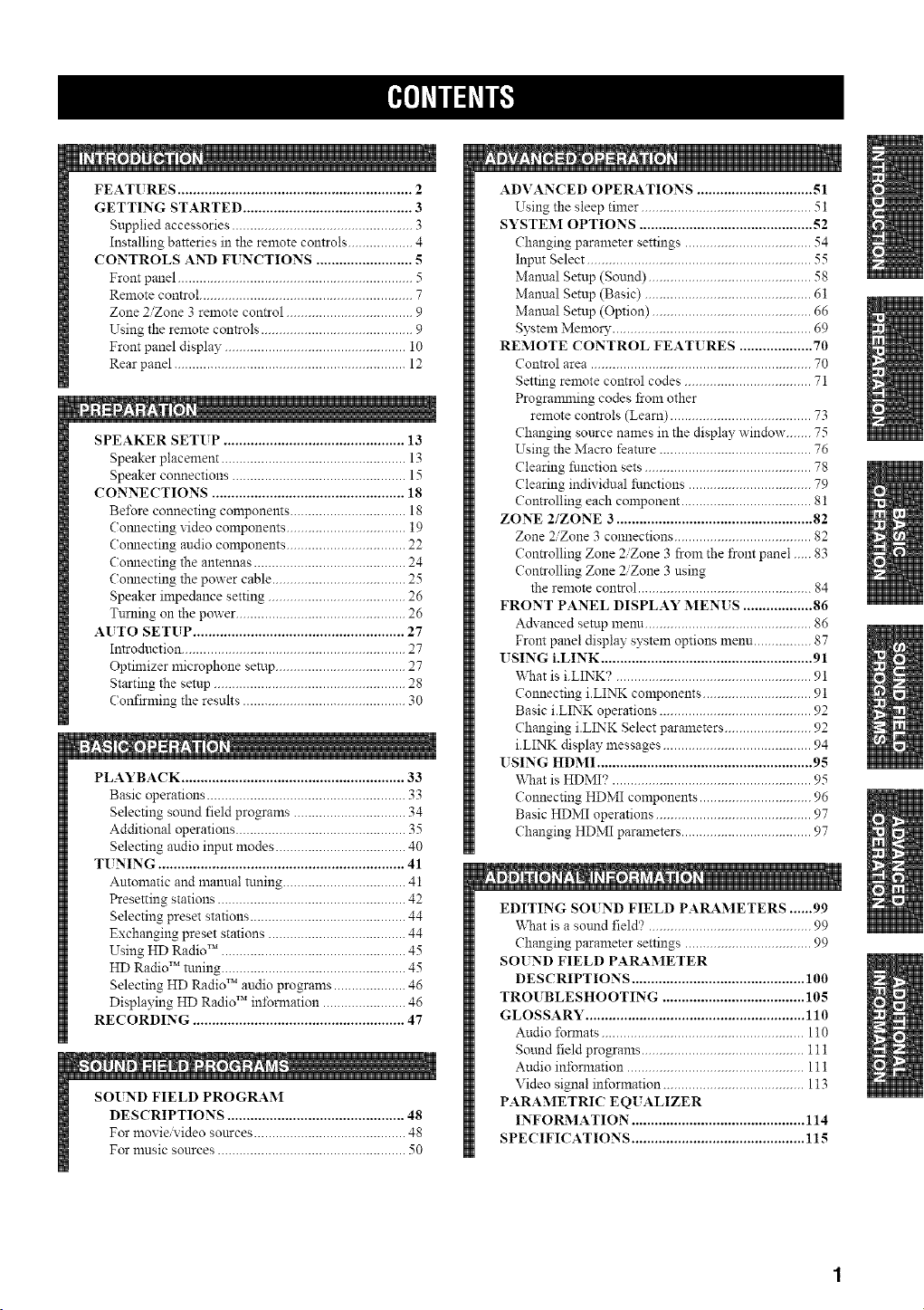
FEATURES ............................................................. 2
GETTING STARTED ............................................ 3
Supplied accessories .................................................. 3
Installing batteries in the remote controls .................. 4
CONTROLS AND FUNCTIONS ......................... 5
Front panel ................................................................. 5
Remote control ........................................................... 7
Zone 2/Zone 3 remote control ................................... 9
Using the remote controls .......................................... 9
Front panel display .................................................. 10
Rear panel ................................................................ 12
SPEAKER SETUP ............................................... 13
Speaker placement ................................................... 13
Speaker connections ................................................ 15
CONNECTIONS .................................................. 18
Be_bre connecting components ................................ 18
Comlecting video components ................................. 19
Comlecting audio components ................................. 22
Cormecting the antennas .......................................... 24
Cormecting the power cable ..................................... 25
Speaker impedance setting ...................................... 26
Turning on the power ............................................... 26
AUTO SETUP ....................................................... 27
Introduction .............................................................. 27
Optimizer microphone sen.lp.................................... 27
Starting the setup ..................................................... 28
Confirming the results ............................................. 30
PLAYBACK .......................................................... 33
Basic operations ....................................................... 33
Selecting sound field programs ............................... 34
Additional operations ............................................... 35
Selecting audio input modes .................................... 40
TUNING ................................................................ 41
Automatic and manual n.ming .................................. 41
Presetting stations .................................................... 42
Selecting preset stations ........................................... 44
Exchanging preset stations ...................................... 44
Using HD Radio TM ................................................... 45
HD Radio TM tuning ................................................... 45
Selecting HD Radio TM audio programs .................... 46
Displaying HD Radio TM infomlation ....................... 46
RECORDING ....................................................... 47
[]
SOUND FIELD PROGI_&M
DESCRIPTIONS .............................................. 48
For movie video sonrces .......................................... 48
For nmsic sonrces .................................................... 50
N
ADVANCED OPERATIONS .............................. 51
Using the sleep timer ............................................... 51
SYSTEM OPTIONS ............................................. 52
Changing parameter settings ................................... 54
Input Select .............................................................. 55
Manual Setup (Sound) ............................................. 58
Mannal Setup (Basic) .............................................. 61
Manual Setup (Option) ............................................ 66
System Memory ....................................................... 69
REMOTE CONTROL FEAT[ RES ................... 70
Control area ............................................................. 70
Setting remote control codes ................................... 71
Programlning codes from other
remote controls (Learn) ....................................... 73
Changing sonrce names in the display window....... 75
Using the Macro feature .......................................... 76
Clearing function sets .............................................. 78
Clearing individual fimctions .................................. 79
Controlling each component .................................... 81
ZONE 2/ZONE 3 ................................................... 82
Zone 2/Zone 3 connections ...................................... 82
Controlling Zone 2/Zone 3 from the front panel ..... 83
Controlling Zone 2/Zone 3 using
the remote control ................................................ 84
FRONT PANEL DISPLAY MENUS .................. 86
Advanced setup menn .............................................. 86
Front panel display system options menu ................ 87
USING i.LINK ....................................................... 91
What is i.LINK? ...................................................... 91
Connecting i.LINK components .............................. 91
Basic i.LINK operations .......................................... 92
Changing i.LINK Select parameters ........................ 92
i.LINK display messages ......................................... 94
USING HDMI ........................................................ 95
What is HDMI? ....................................................... 95
Connecting HDMI components ............................... 96
Basic HDMI operations ........................................... 97
Changing HDMI parameters .................................... 97
m
EDITING SOIND FIELD PAI_&METERS ...... 99
What is a sotmd field'? ............................................. 99
Changing parameter settings ................................... 99
SOIND FIELD PARAMETER
DESCRIPTIONS ............................................. 100
TROUBLESHOOTING ..................................... 105
GLOSSARY ......................................................... 110
Audio ±\mnats ........................................................ 110
Sound field programs ............................................. 111
Audio in±bmlation ................................................. 111
Video signal information ....................................... 113
PARAMETRIC EQ[ ALIZER
INFOR2MATION ............................................. 114
SPECIFICATIONS ............................................. 115
Built-in 7-channel power amplifier
4_ Mininmm RMS Output Power
(0.04% THD, 20 Hz to 20 kHz, 8 _Q)
Front: 130 W + 130 W
Center: 130 W
Sun'ound: 130 W + 130 W
Sun'ound Back: 130 W + 130 W
Sound field features
4_ Proprieta W YAMAHA technology for the creation of"
sound fields
4_ THX Select2
SRS CS i1 (U.S.A. model only)
4_ Dolby DigitaliDolby Digital EX decoder
4_ DTSiDTS-ES Matrix 6.1, Discrete 6.1,
DTS Neo:6 decoder, DTS 96/24
Dolby Pro Logic_olby Pro Logic 1I
Dolby Pro Logic ]lx decoder
Virtual CINEMA DSP
4_ SILENT CINEMA TM
Sophisticated AM/FM tuner
4_ 40-station random access preset tuning
4_ Automatic preset tuning
4_ Preset station shifting capability (preset editing)
4_ HD Radio TM digital broadcast reception capability
• *"4"-indicates a tip for your operation.
Other features
YPAO: YAMAHA Parametric Room Acoustic
Optimizer for automatic speaker setup
192-kHzi2 4-bit Di A converter
GUI (graphical user interface) menus that allow you to
optimize this unit to suit your individual audio/video
system
I_ 6 or 8-channel additional input jacks lbr discrete
multi-channel input
• ' Short message function
PURE DIRECT for pure fidelity sound with analog,
DSD, PCM and multi-channel PCM sources
• ' S-video signal input/output capability
• ' Component video input, output capability
I_ Video signal conversion (composite video ++
S-video > component video) capability for monitor
out
I_ i.LINK inter_ace for direct digital transfer of digital
audio signals
I_ HDMI interface for standard, enhanced or
high-definition video as well as nmlti-channel digital
audio
Optical and coaxial digital audio signal jacks
I_ Sleep timer
I_ Cinema and music night listening mode
I_ Remote control with preset remote control codes and
learning macro capability
I_ Zone 2/Zone 3 custom installation facility
I_ Zone 2/Zone 3 remote control for controlling
Zone ZZone 3 components connected to this unit
• Some operations can be peribrmed by using either the buttons on the main unit or on the remote control. In cases when the breton
names differ between the main trait and the remote control, the button nan_e on the remote control is given in parentheses.
• This manual is printed prior to production. Design and specifications are sulziect to change in part as a result of improvements, etc.
In case of difEerences between the mannal and product, the product has priority.
D_GITAL + EX
IL;® +
Manufactured under license froln Dolby Laboratories.
"Dolby", "Snrround EX", and the double-D symbol are
trademarks of Dolby Laboratories.
.LINK andthe 1.LI_K logo g are trademarks of Sony
Corporation.
SILENT '_
CINEMA
"SILENT CINEMA" is a trademark of YAMAHA
CORPORATION.
"DTS", "DTS-ES", "Neo:6" and "DTS 96/24" are trademarks of
Digital Theater Systems. Inc.
H 2JrgH
"HDMI", the "HDMI" logo and "High-Definition Multimedia
Interface" are trademarks or registered trademarks of HDMI
Licensing LLC.
HD RadioTM technology manufactured under license from
iBiquity Digital Corporation. "iBiquity Digital" and the "HD
Radio" and "HD" symbols are registered trademarks of iBiqtdty
Digital Corporation. U.S. and Foreign Patents.
Circle Surround I1, Dialog Clarity, TruBass. SRS and the (o>
symbol are trademarks of SRS Labs, Inc.
Circle Surrotmd II, Dialog Clarity and TruBass technologies are
incorporated under license from SRS Labs. Inc.
The THX logo is a trademark of THX Ltd. which may be
registered in some jurisdictions. All rights reserved.
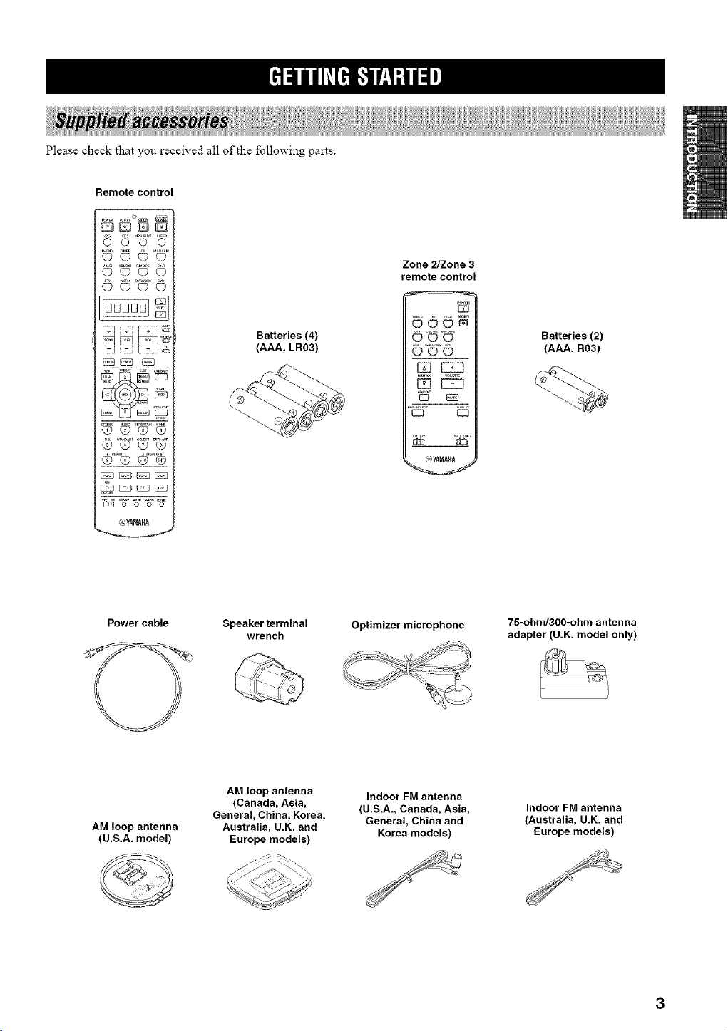
Please check that you received all of the following parts.
Remote control
5 D°N_
0©00
000©
O_Q_
0_0_
0111111
Batteries (4)
(AAA, LR03)
Zone _Zone3
remote control
d©©W
©'6-©"
©©©
[2312751
D
C] K73
...... z0,E,z0,E_
Batteries (2)
(AAA, R03)
Power cable
Speaker terminal
wrench
Optimizer microphone
75-ohnd300-ohm antenna
adapter (U.K. model only)
AM loop antenna
(U.S.A. model)
G
AM loop antenna
(Canada, Asia,
General, China, Korea,
Australia, U.K. and
Europe models)
Indoor FM antenna
(U.S.A., Canada, Asia,
General, China and
Korea models)
Indoor FM antenna
(Australia, U.K. and
Europe models)
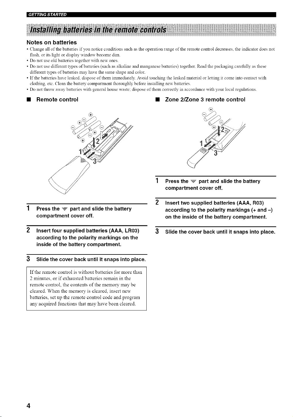
Notes on batteries
• Change all of the batteries if you notice conditions such as the operation range of the remote control decreases, the indicator does not
flash, or its light or display window become dim.
• Do not use old batteries together with new ones.
• Do not use different t?_pes of batteries (such as alkaline and manganese batteries) together. Read the packaging carefi.dly as these
different types of batteries may have the same shape and color.
• If the batteries have leaked, dispose of them in_nediately. Avoid touching the leaked material or letting it come into contact with
clothing, etc. Clean the batter?,, comparm_ent thoroughly before installing new batteries.
• Do not throw away batteries with general house waste: dispose of them correctly in accordance with your local regulations.
• Remote control • Zone 2/Zone 3 remote control
1 Press the _ part and slide the battery
compartment cover off.
2 Insert four supplied batteries (AAA, LR03)
according to the polarity markings on the
inside of the battery compartment.
3 Slide the cover back until it snaps into place.
If the remote control is without batteries for more than
2 minutes, or if exhausted batteries remain in the
remote control, the contents of the memory may be
cleared. When the memory is cleared, insert new
batteries, set up the remote control code and program
any acquired fimetions that may have been cleared.
Press the _ part and slide the battery
compartment cover off.
Insert two supplied batteries (AAA, R03)
according to the polarity markings (+ and -)
on the inside of the battery compartment.
3 Slide the cover back until it snaps into place.
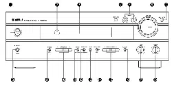
Q • O
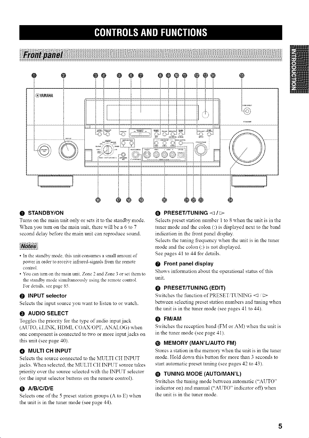
O STANDBY/ON
Turns on the main unit only or sets it to the standby mode.
When you turn on the main unit, there will be a 6 to 7
second delay before the main unit can reproduce sound.
• In the standby mode, this unit consmnes a small amount of
power in order to receive infrared-signals from the remote
control.
• You can turn on the main unit, Zone 2 and Zone 3 or set them to
the standby mode simultaneously using the remote control.
For details, see page 85.
O INPUT selector
Selects the input source you want to listen to or watch.
O AUDIO SELECT
Toggles the priority for the type of audio input jack
(AUTO, iiINK, HDMI, COAX/OPT, ANALOG) when
one component is connected to two or more input jacks on
this unit (see page 40).
• MULTI CH INPUT
Selects the source connected to the MULTI CH INPUT
jacks. When selected, the MULTI CH INPUT source takes
priority over the source selected with the INPUT selector
(or the input selector buttons on the remote control).
0 A/BIC/DIE
Selects one of the 5 preset station groups (A to E) when
the unit is in the tuner mode (see page 44).
O PRESET/TUNING <1/C>
Selects preset station number 1 to 8 when the unit is in the
tuner mode and the colon (:) is displayed next to the band
indication in the front panel display.
Selects the tuning frequency when the unit is in the tuner
mode and the colon (:) is not displayed.
See pages 41 to 44 for details.
O Front panel display
Shows information about the operational stares of this
unit.
O PRESET/TUNING (EDIT)
Switches the function of PRESET TUNING <1
between selecting preset station numbers and tuning when
the unit is in the tuner mode (see pages 41 to 44).
0 FM/AM
Switches the reception band (FM or AM) when the unit is
in the tuner mode (see page 41).
@ MEMORY (MAN'L/AUTO FM)
Stores a station in the lIlelIlOfy when the unit is in the tuner
mode. Hold down this button for more than 3 seconds to
start automatic preset tuning (see pages 42 to 43).
• TUNING MODE (AUTO/MAN'L)
Switches the tuning mode between automatic ("AUTO"
indicator on) and manual ("AUTO" indicator of'l) when
the unit is in the tuner mode.
O STRAIGHT/EFFECT
Switches the sound fields off or on. When STRAIGHT is
selected, input signals (2-channel or multi-channel) are
output directly from their respective speakers without
effect processing.
@ Remote control sensor
Receives signals from the remote controls.
• TONE CONTROL
Use to adjust the bass treble balance for the front left right
and center channels (see page 35).
O PURE DIRECT
Turns on 02"off the PURE DIRECT mode. Lights up when
mined on (see page 38).
@ REC OUT/ZONE 2
Selects the source you want to direct to the audio video
recorder and ZONE 2 outputs independently of the source
you are listening to or watching in the main room. When
set to the SOURCE.REMOTE position, the input source is
directed to all outputs. The source in Zone 2 and the
source you record are always identical.
• OPTIMIZER MIC jack
Use to connect and input audio signals from the supplied
microphone for use with the AUTO SETUP function
(see page 27).
_) SPEAKERS A/B
Turn o1"1or off the set of front speakers connected to the
A and/or B terminals on the rear panel each time the
corresponding button is pressed.
@ _ PHONES (SILENT CINEMA) jack
Outputs audio signals lbr private listening with
headphones. When you connect hea@hones, no signals
are output at the PRE OUT jacks or to the speakers.
All Dolby Digital and DTS audio signals are mixed down
to the front left and right channels.
_} VIDEO AUX jacks
Input audio and video signals fi'om an extemal source
such as a game console. To reproduce source signals at
these jacks, select V-AUX as the input source.
@ ZONE ON/OFF
MAIN
Turns on the power of the main unit or sets it to the
standby mode (see page 83).
ZONE 2
Turns on the power of Zone 2 02"sets it to the standby
mode (see page 83).
ZONE 3
Turns on the power of Zone 3 02"sets it to the standby
mode (see page 83).
_) ZONE CONTROL
Press to control the input or adjust the volume level for the
currently selected zone (the main unit, Zone 2 or Zone 3)
(see page 83). After you press ZONE CONTROL, the
indicator for the currently selected zone flashes in the
l_cont panel display for approximately 5 seconds. While the
indicator is flashing, perform the desired operation.
PROGRAM selector
Use to select sound field programs 02"adjust bass.treble
balance (in conjunction with TONE CONTROL).
_) VOLUME
Controls the output level of all audio channels.
This does not affect the REC OUT level.
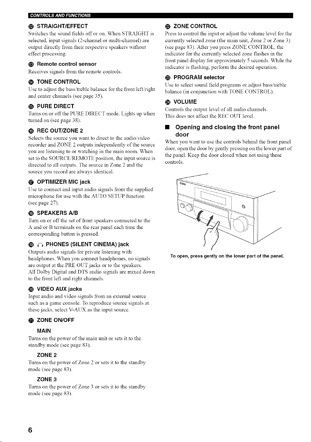
• Opening and closing the front panel
door
When you want to use the controls behind the fi'ont panel
door, open the door by gently pressing on the lower part of
the panel. Keep the door closed when not using these
controls.
To open, press gently on the lower part of the panel.
_o]dll;{o]ik'JF:hqlJ_lJd[ell[o]dt.
This section describes the function of each control on the
remote control used to control this unit. To operate other
components, see "REMOTE CONTROL FEATURES" on
page 70. Set AMPiSOURCEiTV to AMP to operate this
unit.
O .........
O ............
(N3 GD
© ©
TUNER ¢D _It,lULTFCHIN
CBL/SAT MDFrApE CD_"""" '-_R_''_I
VCR I DW_VCR2 DVD
C) O
SOURCE
L2_J ©
STEREO MUSIC ENTERTAIN MOWE
OOCDO
TH× S_'ANDARD SELECT EXTDSUn./
CDQOQ/
Q©
.....................................,!
@YANAHA
--@
--@
--@
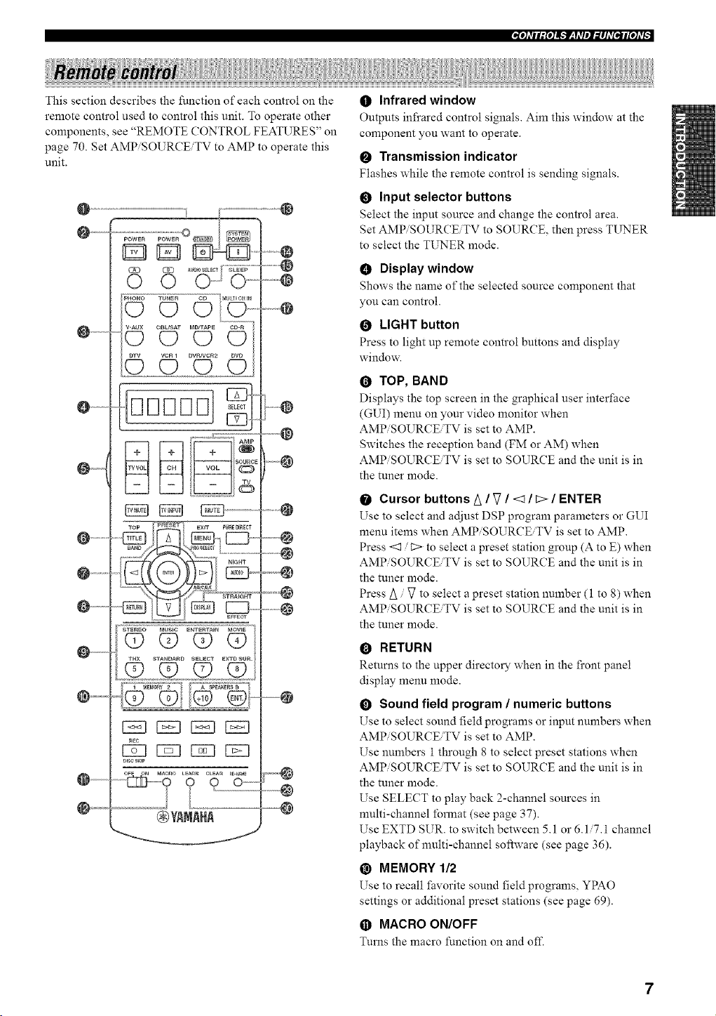
O Infrared window
Outputs infrared control signals. Aim this window at the
component you want to operate.
O Transmission indicator
Flashes while the remote control is sending signals.
Input selector buttons
Select the input source and change the control area.
Set AMPiSOURCEiTV to SOURCE, then press TUNER
to select the TUNER mode.
• Display window
Shows the name of the selected source component that
you can control.
LIGHT button
Press to light up remote control buttons and display
windox_
TOP, BAND
Displays the top screen in the graphical user interface
(GUI) menu on your video monitor when
AMPiSOURCEiTV is set to AMP.
Switches the reception band (FM or AM) when
AMPiSOURCEiTV is set to SOURCE and the unit is in
the tuner mode.
Cursor buttons A / V / <1 / L> / ENTER
Use to select and adjust DSP program parameters o1"GUI
menu items when AMPiSOURCEiTV is set to AMP.
Press <1 /C> to select a preset station group (A to E) when
AMPiSOURCEiTV is set to SOURCE and the unit is in
the tuner mode.
Press/_ / _ to select a preset station number (1 to 8) when
AMPiSOURCEiTV is set to SOURCE and the unit is in
the tuner mode.
RETURN
Returns to the upper directory when in the front panel
display menu mode.
0 Sound field program / numeric buttons
Use to select sound field programs or input numbers when
AMPiSOURCEiTV is set to AMP.
Use numbers 1 through 8 to select preset stations when
AMPiSOURCEiTV is set to SOURCE and the unit is in
the tuner mode.
Use SELECT to play back 2-channel sources in
nmlti-channel format (see page 37).
Use EXTD SUR. to switch between 5.1 or 6.1/7.1 channel
playback of multi-channel software (see page 36).
@ MEMORY 112
Use to recall favorite sound field programs, YPAO
settings or additional preset stations (see page 69).
• MACRO ON/OFF
Turns the macro function on and off.
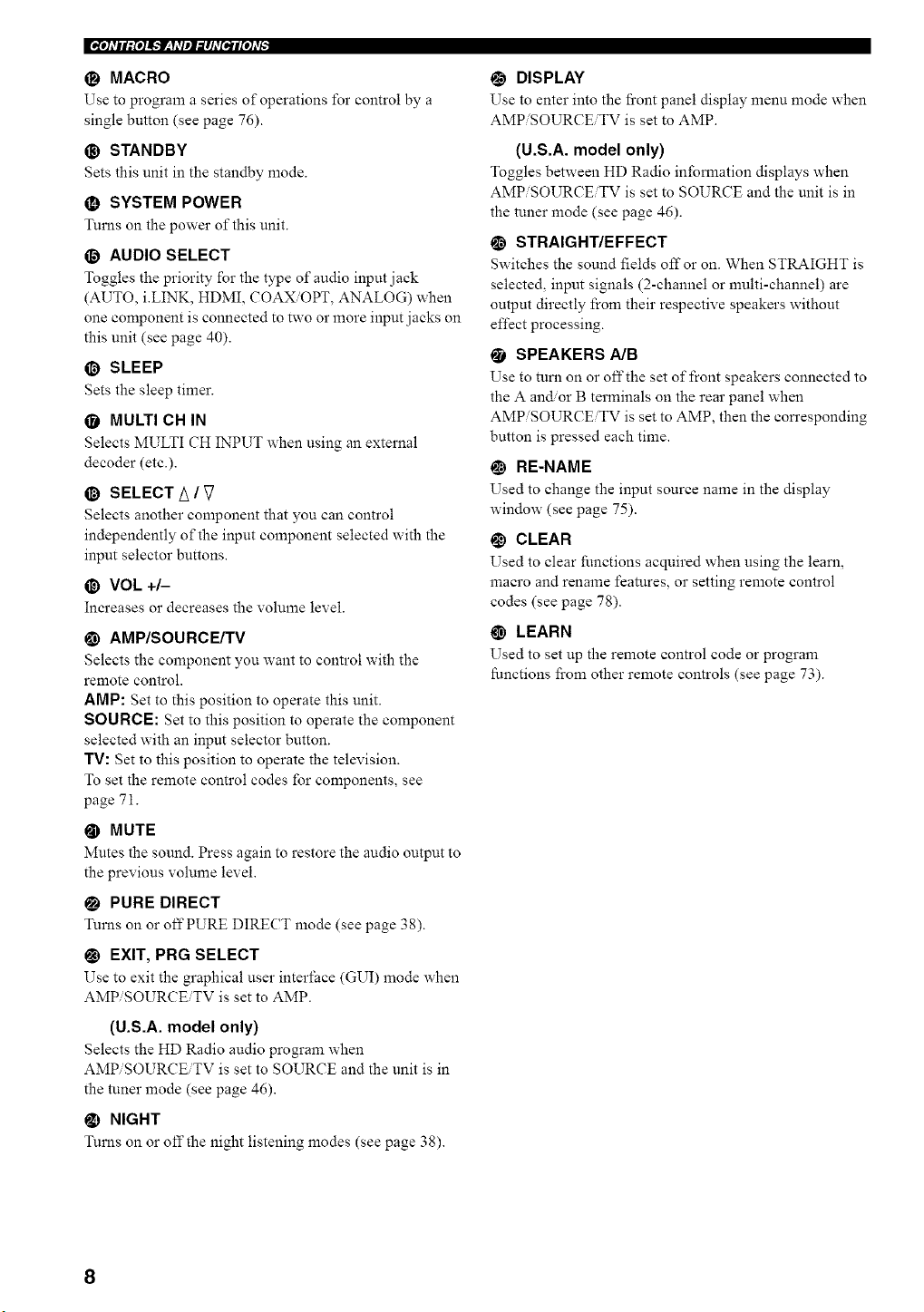
1_ MACRO
Use to program a series of operations 1"o1"control by a
single button (see page 76).
O STANDBY
Sets this unit in the standby mode.
O SYSTEM POWER
Turns on the power of this unit.
O AUDIO SELECT
Toggles the priority l"orthe type of audio input jack
(AUTO, i.LINK, HDMI, COAX/OPT, ANALOG) when
one component is connected to two or more input jacks on
this unit (see page 40).
@ SLEEP
Sets the sleep timer.
• MULTI CH IN
Selects MULTI CH INPUT when using an external
decoder (etc.).
@ SELECT/_ / V
Selects another component that you can control
independently of the input component selected with the
input selector buttons.
@ VOL +/-
Increases or decreases the vohnne level.
@ AMP/SOURCE/TV
Selects the component you want to control with the
remote control.
AMP: Set to this position to operate this unit.
SOURCE: Set to this position to operate the component
selected with an input selector button.
TV: Set to this position to operate the television.
To set the remote control codes for components, see
page 71.
@ MUTE
Mutes the sound. Press again to restore the audio output to
the previous volume level.
PURE DIRECT
Turns on or off PURE DIRECT mode (see page 38).
_1 EXIT, PRG SELECT
Use to exit the graphical user interface (GUI) mode when
AMPiSOURCEiTV is set to AMP.
(U.S.A. model only)
Selects the HD Radio audio program when
AMPiSOURCEiTV is set to SOURCE and the unit is in
the tuner mode (see page 46).
NIGHT
Turns on or off the night listening modes (see page 38).
DISPLAY
Use to enter into the fi'ont panel display menu mode when
AMPiSOURCEiTV is set to AMP.
(U.S.A. model only)
Toggles between HD Radio infomlation displays when
AMPiSOURCEiTV is set to SOURCE and the unit is in
the tuner mode (see page 46).
_) STRAIGHT/EFFECT
Switches the sound fields off or on. When STRAIGHT is
selected, input signals (2-channel or multi-channel) are
output directly from their respective speakers without
effect processing.
• SPEAKERS A/B
Use to turn on or off the set of front speakers connected to
the A and.or B terminals on the rear panel when
AMPiSOURCEiTV is set to AMP, then the corresponding
button is pressed each time.
_) RE-NAME
Used to change the input source name in the display
window (see page 75).
@ CLEAR
Used to clear functions acquired when using the learn,
macro and rename features, or setting remote control
codes (see page 78).
G) LEARN
Used to set up the remote control code or program
functions fi'om other remote controls (see page 73).
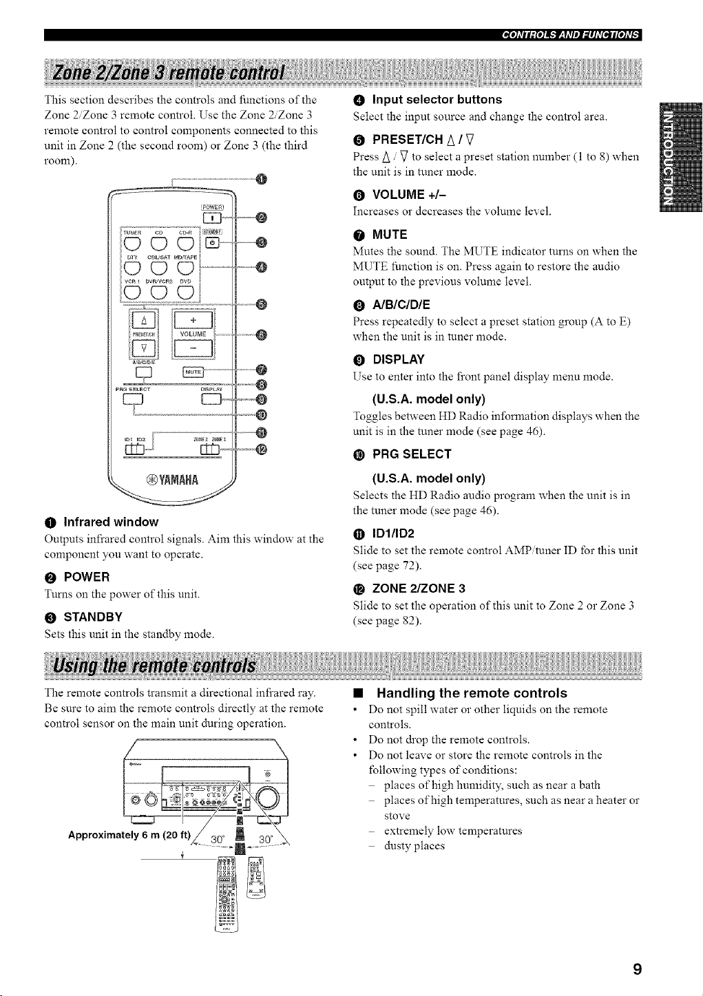
_e]dll;[e]J_'f_qdlel_lJd[e_Jl[e]d[,
This section describes the controls and functions of the
Zone 2/Zone 3 remote control. Use the Zone 2/Zone 3
remote control to control components connected to this
unit in Zone 2 (the second room) or Zone 3 (the third
room).
@
'POWER'
WB/C/O/E /
DlaPLA¥
Z_E_ Z_Ea
@YANAHA
O Infrared window
--@
....... 4_
Outputs infrared control signals. Aim this window at the
component you want to operate.
O POWER
Turns on the power of this unit.
O STANDBY
Sets this unit in the standby mode.
O Input selector buttons
Select the input source and change the control area.
O PRESET/CH A / V
Press/_ / V to select a preset station number (1 to 8) when
the unit is in tuner mode.
O VOLUME +/-
Increases or decreases the volume level.
O MUTE
Mutes the sound. The MUTE indicator turns on when the
MUTE function is on. Press again to restore the audio
output to the previous volume level.
O A/B/C/DIE
Press repeatedly to select a preset station group (A to E)
when the unit is in tuner mode.
O DISPLAY
Use to enter into the front panel display menu mode.
(U.S.A. model only)
Toggles between HD Radio information displays when the
unit is in the tuner mode (see page 46).
@ PRG SELECT
(U.S.A. model only)
Selects the HD Radio audio program when the unit is in
the tuner mode (see page 46).
• IDI/ID2
Slide to set the remote control AMP tuner ID lbr this unit
(see page 72).
O ZONE 2/ZONE 3
Slide to set the operation of this unit to Zone 2 or Zone 3
(see page 82).
The remote controls transmit a directional infi'ared ray.
Be sure to aim the remote controls directly at the remote
control sensor on the main unit during operation.
Approximately 6 m (20 ft)
• Handling the remote controls
• Do not spill water or other liquids on the remote
controls.
• Do not drop the remote controls.
• Do not leave or store the remote controls in the
following types of conditions:
places of high humidity, such as near a bath
places of high temperatures, such as near a heater or
stove
extremely low temperatures
dusty places
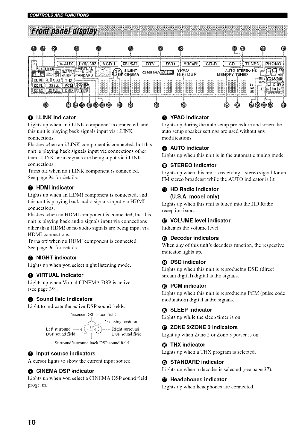
O i.LINK indicator
Lights up when an i.LINK component is connected, and
this unit is playing back signals input via i.LINK
connections.
Flashes when an i.LINK component is connected, but this
unit is playing back signals input via connections other
than i.LINK or no signals are being input via iiINK
connections.
Turns off when no iiINK component is connected.
See page 94 for details.
O HDMI indicator
Lights up when an HDMI component is connected, and
this unit is playing back audio signals input via HDMI
connections.
Flashes when an HDMI component is connected, but this
unit is playing back audio signals input via connections
other than HDMI or no audio signals are being input via
HDMI connections.
Turns off when no HDMI component is connected.
See page 96 for details.
O NIGHT indicator
Lights up when you select night listening mode.
• VIRTUAL indicator
Lights up when Virtual CINEMA DSP is active
(see page 39).
O Sound field indicators
Light to indicate the active DSP sound fields.
Presence DSP sound field
r
/ -x . Listenina position
Left surrour, d ( i '.)._,_): Right surround
DSP sound field " > " .... DSP so_mdfield
Sunotmdisurround back DSP sound field
Input source indicators
A cursor lights to show the current input source.
O CINEMA DSP indicator
Lights up when you select a CINEMA DSP sound field
program.
O YPAO indicator
Lights up during the auto setup procedure and when the
auto setup speaker settings are used without any
modifications.
AUTO indicator
Lights up when this unit is in the automatic tuning mode.
@ STEREO indicator
Lights up when this unit is receiving a stereo signal for an
FM stereo broadcast while the AUTO indicator is lit.
HD Radio indicator
(U.S.A. model only)
Lights up when this unit is tuned into the HD Radio
reception band.
• VOLUME level indicator
Indicates the volume level.
@ Decoder indicators
When any of this unit's decoders function, the respective
indicator lights up.
DSD indicator
Lights up when this unit is reproducing DSD (direct
stream digital) digital audio signals.
O PeN indicator
Lights up when this unit is reproducing PCM (pulse code
modulation) digital audio signals.
@ SLEEP indicator
Lights up while the sleep timer is on.
ZONE 2/ZONE 3 indicators
Light up when Zone 2 or Zone 3 power is on.
@ THX indicator
Lights up when a THX program is selected.
@ STANDARD indicator
Lights up when a decoder is selected (see page 37).
Headphones indicator
Lights up when headphones are connected.
10
@ SP A B indicators
Light up according to the set of front speakers selected.
Both indicators light up when both sets of speakers are
selected, or when bi-wiring.
• SILENT CINEMA indicator
Lights up when headphones are connected and a sound
field program is selected (see page 36).
Multi-information display
Shows the cun'ent sound field program name and other
infomlation when adjusting or changing settings.
_) HiFi DSP indicator
Lights up when you select a HiFi DSP sound field
program.
_) MEMORY indicator
Flashes to show a station can be stored.
!_1 TUNED indicator
Lights up when this unit is tuned into a station.
• MUTE indicator
Flashes while the MUTE function is on.
_) 96/24 indicator
Lights up when a DTS 96/24 signal is input to this unit.
_) LFE indicator
Lights up when the input signal contains an LFE signal.
Input channel indicators
Indicate the channel components of current digital input
signal.
@ Presence and surround back speaker
indicators
Indicate the connection of presence and, or sun'ound back
speakers when using the Auto Setup setting (page 27) or
Speaker Level setting (page 65).
_e]dll;{e]i_NF_qdlel_il]d[eJlr[e]dt,
11
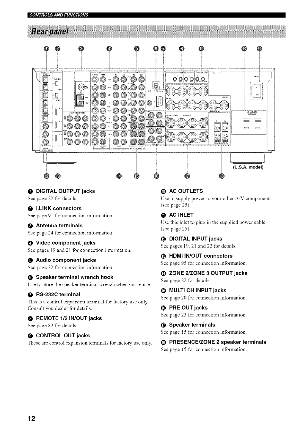
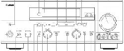
|_[o]dll:{o]i_.'Jr__yd]l]:l]d[tll[o]d[
e o
0 DIGITAL OUTPUT jacks
See page 22 for details.
O i.LINK connectors
See page 91 for connection information.
O Antenna terminals
See page 24 for connection information.
O Video component jacks
See pages 19 and 21 for connection information.
O Audio component jacks
See page 22 for connection information.
O Speaker terminal wrench hook
Use to store the speaker terminal wrench when not in use.
O RS-232C terminal
This is a control expansion terminal for factory use only.
Consult you dealer for details.
O REMOTE 112 IN/OUT jacks
See page 82 for details.
0 CONTROL OUT jacks
These are control expansion terminals for f:actory use only.
@
(U.S.A. model)
@ AC OUTLETS
Use to supply power to your other AV components
(see page 25).
• AC INLET
Use this inlet to plug in the supplied power cable
(see page 25).
O DIGITAL INPUT jacks
See pages 19, 21 and 22 for details.
@ HDMI IN/OUT connectors
See page 95 for connection information.
• ZONE 2/ZONE 3 OUTPUT jacks
See page 82 for details.
O MULTI CH INPUT jacks
See page 20 for connection information.
@ PRE OUT jacks
See page 23 for connection information.
• Speaker terminals
See page 15 for connection information.
@ PRESENCE/ZONE 2 speaker terminals
See page 15 for connection information.
12
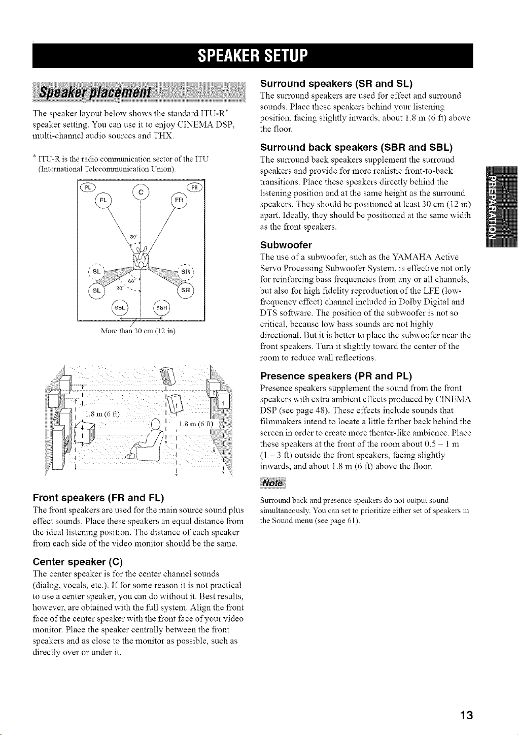
The speaker layout below shows the standard ITU-R*
speaker setting. You can use it to enjoy CINEMA DSP,
multi-channel audio sources and THX.
* ITU-R is the radio commtmication sector of the ITU
(International Teleconmmnication Union).
More than 30 cm (t2 in)
Surround speakers (SR and SL)
The surround speakers are used for effect and surround
sounds. Place these speakers behind your listening
position, facing slightly inwards, about 1.8 m (6 ft) above
the floor.
Surround back speakers (SBR and SBL)
The surround back speakers supplement the surround
speakers and provide for more realistic front-to-back
transitions. Place these speakers directly behind the
listening position and at the same height as the sun'ound
speakers. They should be positioned at least 30 cm (12 in)
apart. Ideally, they should be positioned at the same width
as the front speakers.
Subwoofer
The use of a subwoofer, such as the YAMAHA Active
Servo Processing Subwoofer System, is effective not only
for reinforcing bass fi'equencies fi'om any or all channels,
but also for high fidelity reproduction of the LFE (low-
frequency effect) channel included in Dolby Digital and
DTS software. The position of the subwoofer is not so
critical, because low bass sounds are not highly
directional. But it is better to place the subwoofer near the
front speakers. Turn it slightly toward the center of the
room to reduce wall reflections.
Presence speakers (PR and PL)
Presence speakers supplement the sound from the front
speakers with extra ambient effects produced by CINEMA
DSP (see page 48). These effects include sounds that
filmmakers intend to locate a little fi_rther back behind the
screen in order to create more theater-like ambience. Place
these speakers at the front of the room about 0.5 1 m
(1 3 R) outside the front speakers, facing slightly
inwards, and about 1.8 m (6 ft) above the floor.
Front speakers (FR and FL)
The l_ont speakers are used for the main source sound plus
effect sounds. Place these speakers an equal distance fi'om
the ideal listening position. The distance of each speaker
from each side of the video monitor should be the same.
Center speaker (C)
The center speaker is for the center channel sounds
(dialog, vocals, etc.). If for some reason it is not practical
to use a center speaker, you can do without it. Best results,
however, are obtained with the full system. Align the front
face of the center speaker with the front face of your video
monitor. Place the speaker centrally between the front
speakers and as close to the monitor as possible, such as
directly over or under it.
Surround back and presence speakers do not output sound
simultaneousl?: You can set to prioritize either set of speakers in
the Sound menu (see page 61).
13
IFI+IRf+<+N+-'I-.-ilq+
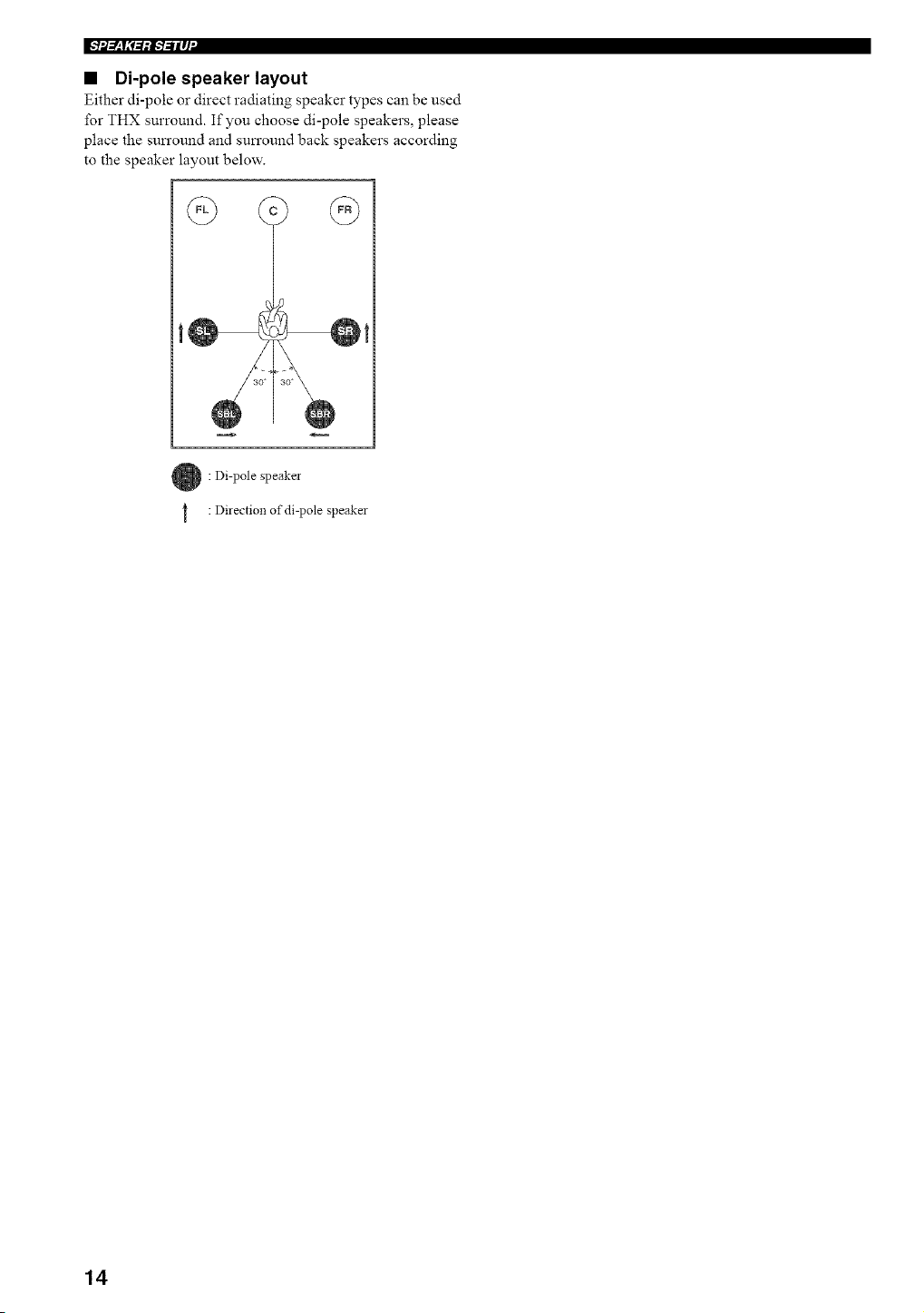
• Di-pole speaker layout
Either di-pole or direct radiating speaker types can be used
for THX surround. If you choose di-pole speakers, please
place the sun'ound and sun'ound back speakers according
to the speaker layout below.
: Di-pole speaker
: Direction of di-pole speaker
14
i+_ f+1.+,+I--I--iiif+
Be sure to connect the left channel (L), right channel (R),
'%" (red) and .... (black) properly. If the connections are
faulty, no sound will be heard from the speakers, and if the
polarity of the speaker connections is incorrect, the sound
will be unnatural and lack bass.
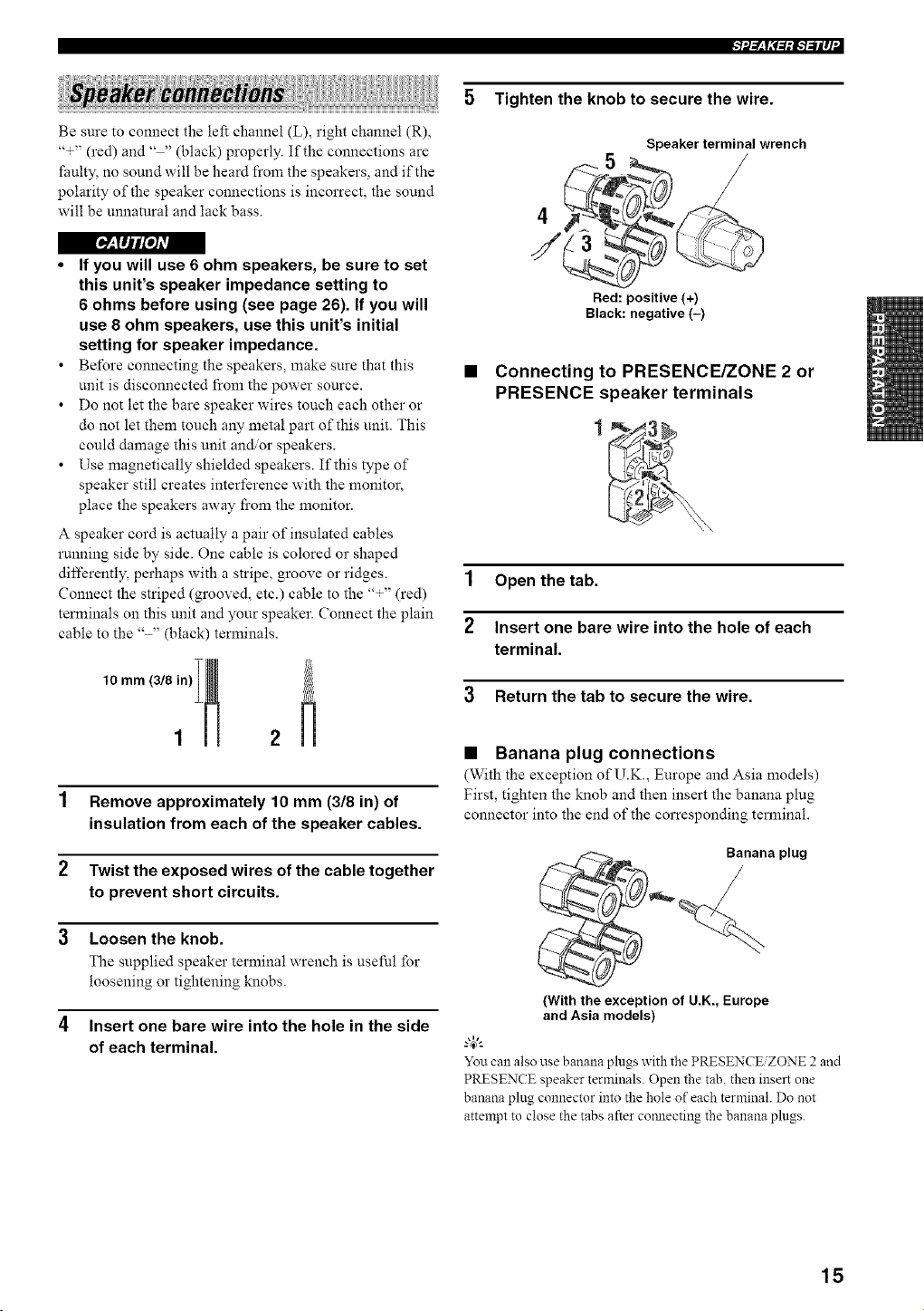
Tighten the knob to secure the wire.
Speaker terminal wrench
5
/
4
[O'_+I Ij I'l'o/AVl
• If you will use 6 ohm speakers, be sure to set
this unit's speaker impedance setting to
6 ohms before using (see page 26). If you will
use 8 ohm speakers, use this unit's initial
setting for speaker impedance.
• Before connecting the speakers, make sure that this
unit is disconnected from the power source.
• Do not let the bare speaker wires touch each other or
do not let them touch any metal part of this unit. This
could damage this unit and/or speakers.
• Use magnetically shielded speakers. If this type of
speaker still creates interference with the monitor,
place the speakers away fi'om the monitor.
A speaker cord is actually a pair of insulated cables
running side by side. One cable is colored or shaped
differently+ perhaps with a stripe, groove or ridges.
Connect the striped (grooved, etc.) cable to the '%" (red)
terminals on this unit and your speaker. Connect the plain
cable to the .... (black) terminals.
1 Remove approximately 10 mm (3/8 in) of
insulation from each of the speaker cables.
2 Twist the exposed wires of the cable together
to prevent short circuits.
3 Loosen the knob.
The supplied speaker terminal wrench is useful for
loosening or tightening knobs.
4 Insert one bare wire into the hole in the side
of each terminal.
Red: positive (+)
Black: negative (-)
• Connecting to PRESENCE/ZONE 2 or
PRESENCE speaker terminals
1 Open the tab.
2 Insert one bare wire into the hole of each
terminal.
3 Return the tab to secure the wire.
• Banana plug connections
(With the exception of U.K., Europe and Asia models)
First, tighten the knob and then insert the banana plug
connector into the end of the corresponding terminal.
Banana plug
{With the exception of U.K., Europe
and Asia models)
g4_"-
Youcan also use banana plugs with the PRESENC_ZONE 2 and
PRESENCE speaker terminals. Open the tab, then insert one
banana plug connector into the hole of each terminal. Do not
attempt to close the tabs after comlecting the banana plugs.
15
IFI+IRf+<+N+-'I-.-ilq+
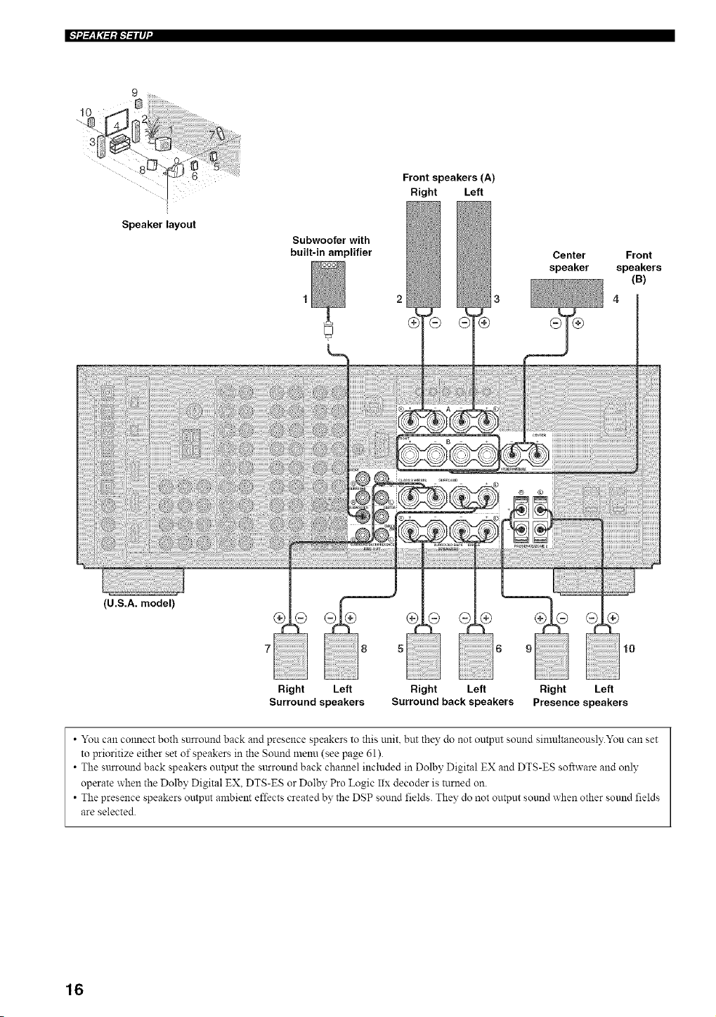
Speaker layout
Subwoofer with
built-in amplifier
Front speakers (A)
Right Left
2 3
Center
speaker
Front
speakers
(B)
4
(U.S.A. model)
7 !ii!ii!ii!ii!ii!ii! i i !+i ij,i,!,!
Right Left
Surround speakers
10
Right Left Right Left
Surround back speakers Presence speakers
• You can cmmect both surround back and presence speakers to this trait, but they do not output sound sinmltaneously.You can set
to prioritize either set of speakers in the Sound menu (see page 61).
• The snrroulld back speakers output the sttrround back chamlel included in Dolby Digital EX and DTS-ES software and only
operate when the Dolby Digital EX. DTS-ES or Dolby Pro Logic Ilx decoder is turned on.
• The presence speakers output ambient effects created by the DSP sound fields+ They do not output sound when other sound fields
are selected.
16
• FRONT terminals
Connect one o1"two speaker systems to these terminals.
If you use only one speaker system, connect it to either of
the FRONT A or B terminals.
The Canada model cannot output to two separate speaker systems
simultaneously.
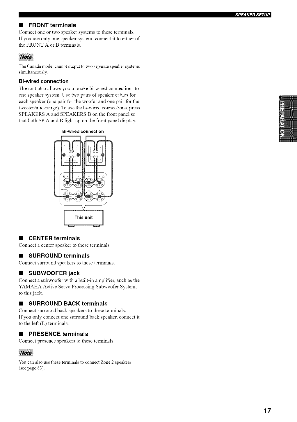
Bi-wired connection
The unit also allows you to make bi-wired connections to
one speaker system. Use two pairs of speaker cables for
each speaker (one pair for the woofer and one pair for the
tweetermid-range). To use the bi-wired connections, press
SPEAKERS A and SPEAKERS B on the front panel so
that both SPA and B light up on the front panel display.
Bi-wired connection
I 1
V
• CENTER terminals
Connect a center speaker to these terminals.
• SURROUND terminals
Connect surround speakers to these terminals.
• SUBWOOFER jack
Connect a subwoofer with a built-in amplifier_ such as the
YAMAHA Active Selwo Processing Subwoofer System,
to this jack.
• SURROUND BACK terminals
Connect sun'ound back speakers to these terminals.
If you only connect one sun'ound back speaker, connect it
to the left (L) terminals.
• PRESENCE terminals
Connect presence speakers to these terminals.
You can also use these terminals to connect Zone 2 speakers
(see page 83).
17
[_:lIHr*1#|
Do not connect this unit or other components to the mains
power until all connections between components are
complete.
• Cable indications
For analog signals
left analog cables _rll _ "
iight analog cables _JH_ "
For digital signals
optical cables _ =oF
coaxial cables _lclL
For video signals
video cables _
S-video cables -ql_"
• Analog jacks
You can input analog signals from audio components by
connecting audio pin cables to the analog jacks on this
unit. Connect red plugs to the right jacks and white plugs
to the left jacks.
• Digital jacks
This unit has digital j acks lbr direct transmission of digital
signals through either coaxial or fiber optic cables. You
can use the digital jacks to input PCM, Dolby Digital and
DTS bitstreams. When you connect components to both
the COAXIAL and OPTICAL jacks, priority is given to
signals input at the COAXIAL jack. All digital input jacks
are compatible with 96-kHz sampling digital signals.
This unit handles digital and analog signals independently. Thus
audio signals inpnt at the analog jacks are only output at the
analog OUT (REC)jacks. Likewise audio signals inpnt at the
digital (OPTICAL or COAXIAL) jacks are only outpnt at the
DIGITAL OUTPUT jacks.
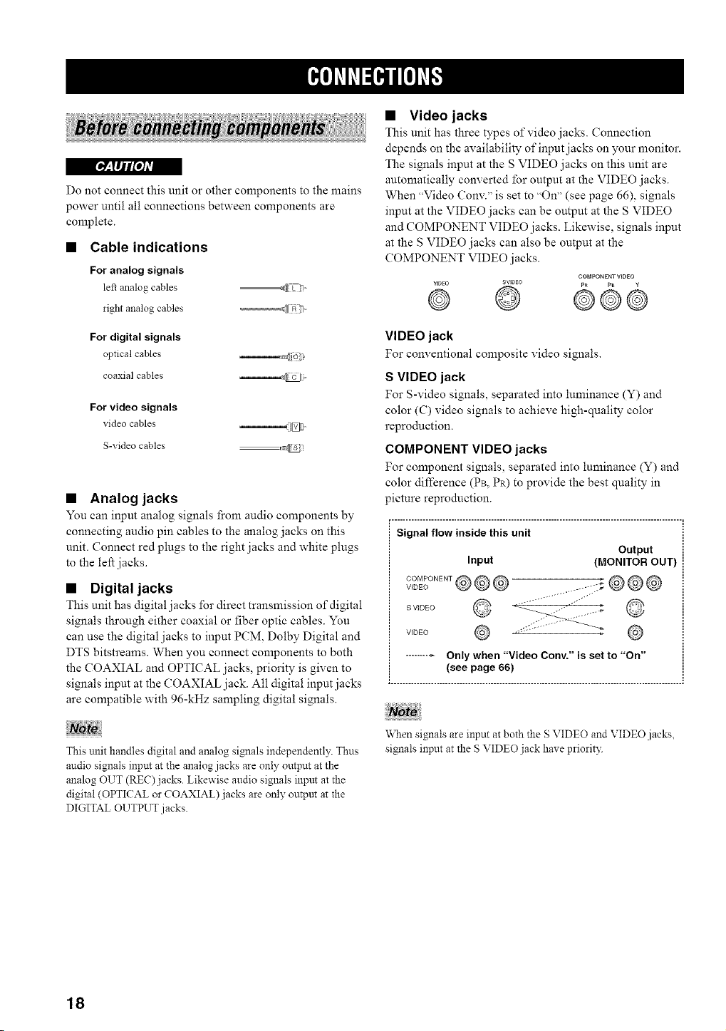
• Video jacks
This unit has three types of video jacks. Connection
depends on the availability of input jacks on your monitor.
The signals input at the S VIDEO jacks on this unit are
automatically converted for output at the VIDEO jacks.
When "Video Conv." is set to "On" (see page 66), signals
input at the VIDEO jacks can be output at the S VIDEO
and COMPONENT VIDEO jacks. Likewise, signals input
at the S VIDEO jacks can also be output at the
COMPONENT VIDEO j acks.
CO_._ PONENT VIDEO
VIDEO SVIDBO p_ p_ g
@ @ @@@
VIDEO jack
For conventional composite video signals.
S VIDEO jack
For S-video signals, separated into luminance (Y) and
color (C) video signals to achieve high-quality color
reproduction.
COMPONENT VIDEO jacks
For component signals, separated into luminance (Y) and
color difference (PB, Pa) to provide the best quality in
picture reproduction.
r- ..................................................................................................... ,
Signal flow inside this unit
Output
Input (MONITOR OUT)
.....
S VIDEO
VIDEO ,,_'" ,,
_,Nen signals are input at both the S VIDEO and VIDEO jacks,
signals input at the S VIDEO jack haxe priority.
18
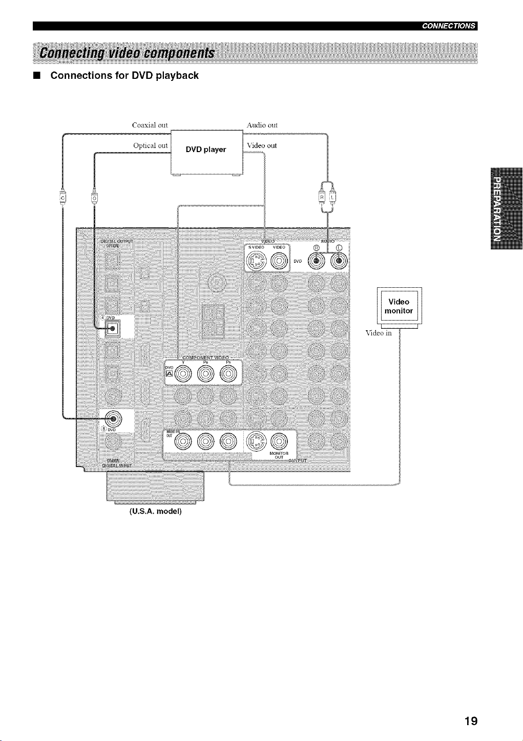
• Connections for DVD playback
Coaxial out
Optical out {_
(U.S.A. model)
DVD player
Audio out
®
Video in
19
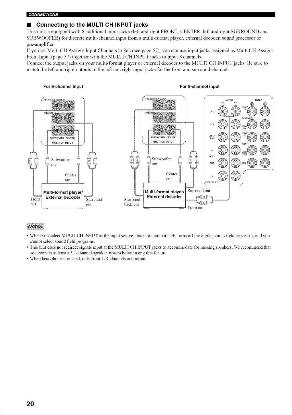
• Connecting to the MULTI CH INPUT jacks
This unit is equipped with 6 additional input jacks (left and right FRONT, CENTER, left and right SURROUND and
SUBWOOFER) for discrete nmlti-channel input from a nmlti-fonnat player, external decoder, sound processor or
pre-amplifier.
If you set Multi CH Assign: Input Channels to 8ch (see page 57), you can use input jacks assigned as Multi CH Assign:
Front Input (page 57) together with the MULTI CH INPUT jacks to input 8 channels.
Connect the output jacks on your multi-format player or external decoder to the MULTI CH INPUT jacks. Be sure to
match the left and right outputs to the left and right input jacks for the front and surround channels.
For 6-channel input For 8-channel input
oTv@
CBU @
SAT
,°@
f
AUDIO AUDIO
® O @ ©
e@2@©
@
CD-R
@
Q/
• "Whenyou select MULTI CH INPUT as the input source, this unit automatically turns offthe digital sound field processor, and you
cannot select sound field programs.
• This unit does not redirect signals input at the MULTI CH INPUT jacks to accommodate for missing speakers. We recommend that
you connect at least a 5.1-channel speaker system be*\_re using this feature.
• When hea@hones are used, only front LiR channels are outpm.
20
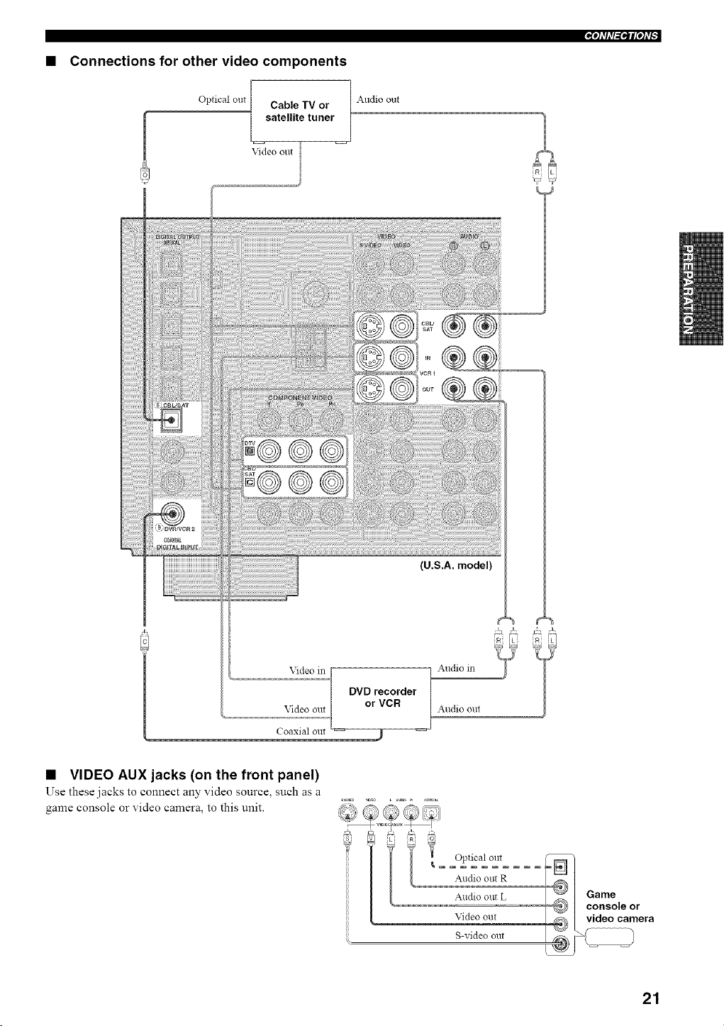
• Connections for other video components
_ql'h'l_f_llql'f
Optical out Cable TV or Audio out
satellite tuner
Video out
{U.S.A. model)
Video in
Video out
Coaxial out
DVD recorder
or VCR
Audio m
Audio out
• VIDEO AUX jacks (on the front panel)
Use these jacks to connect any video source, such as a
game console or video camera, to this unit.
Optical out
Audio out R
Audio out L
Video out
S-video out
21
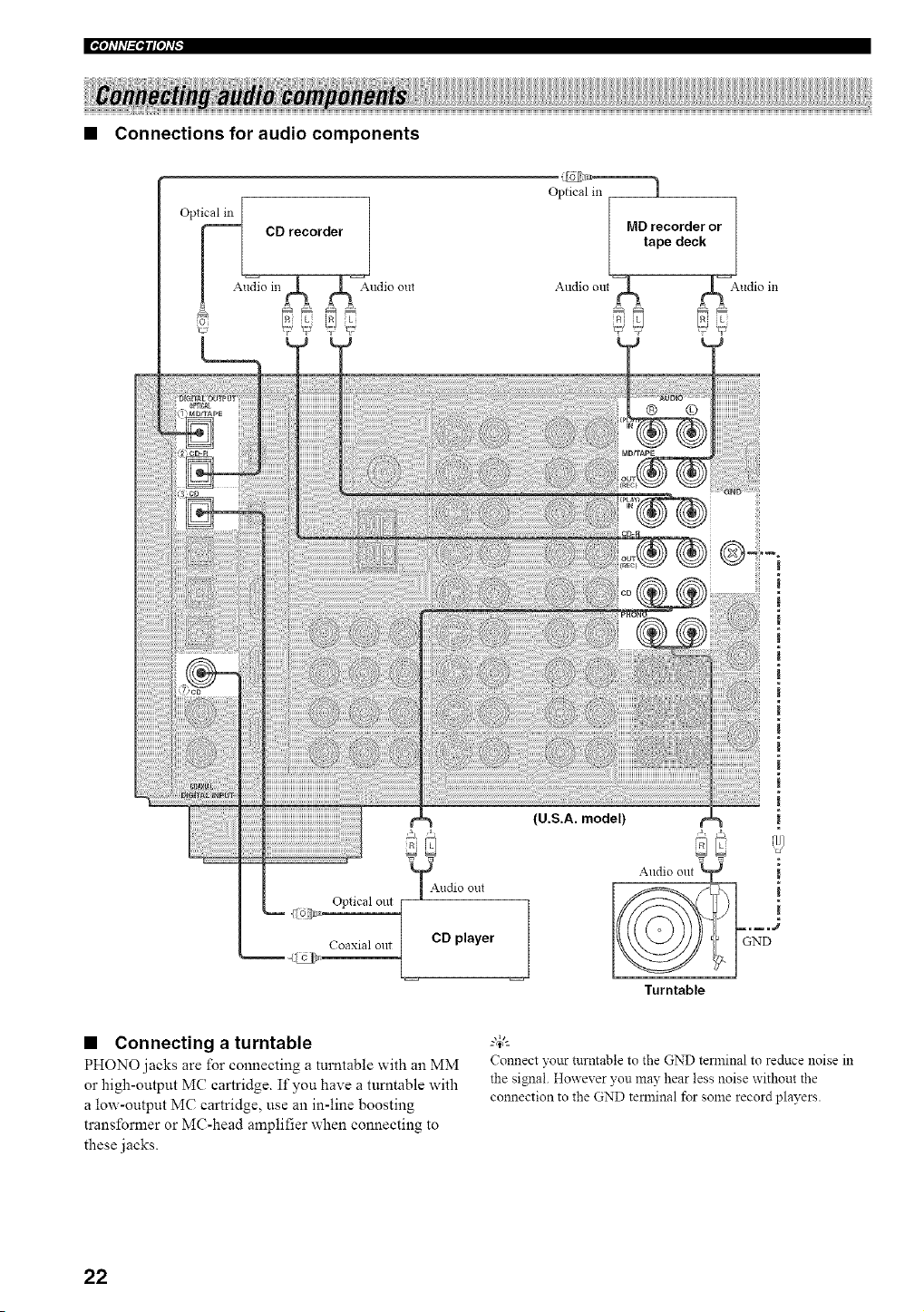
• Connections for audio components
Optical in I
F CD recorder
[ Audi° in A A--Audio out
Audio out
MD recorder or
tape deck
A Audio in
iLi
Optical out j
!
Coaxial out / CD player
(U.S.A. model)
• Connecting a turntable
PHONO jacks are for connecting a turntable with an MM
or high-output MC cartridge. If you have a turntable with
a low-output MC cartridge, use an in-line boosting
transformer or MC-head amplifier when connecting to
these jacks.
Connect your turntable to the GND terminal to reduce noise in
the signal. However you may hear less noise without the
connection to the GND terminal for some record players.
22
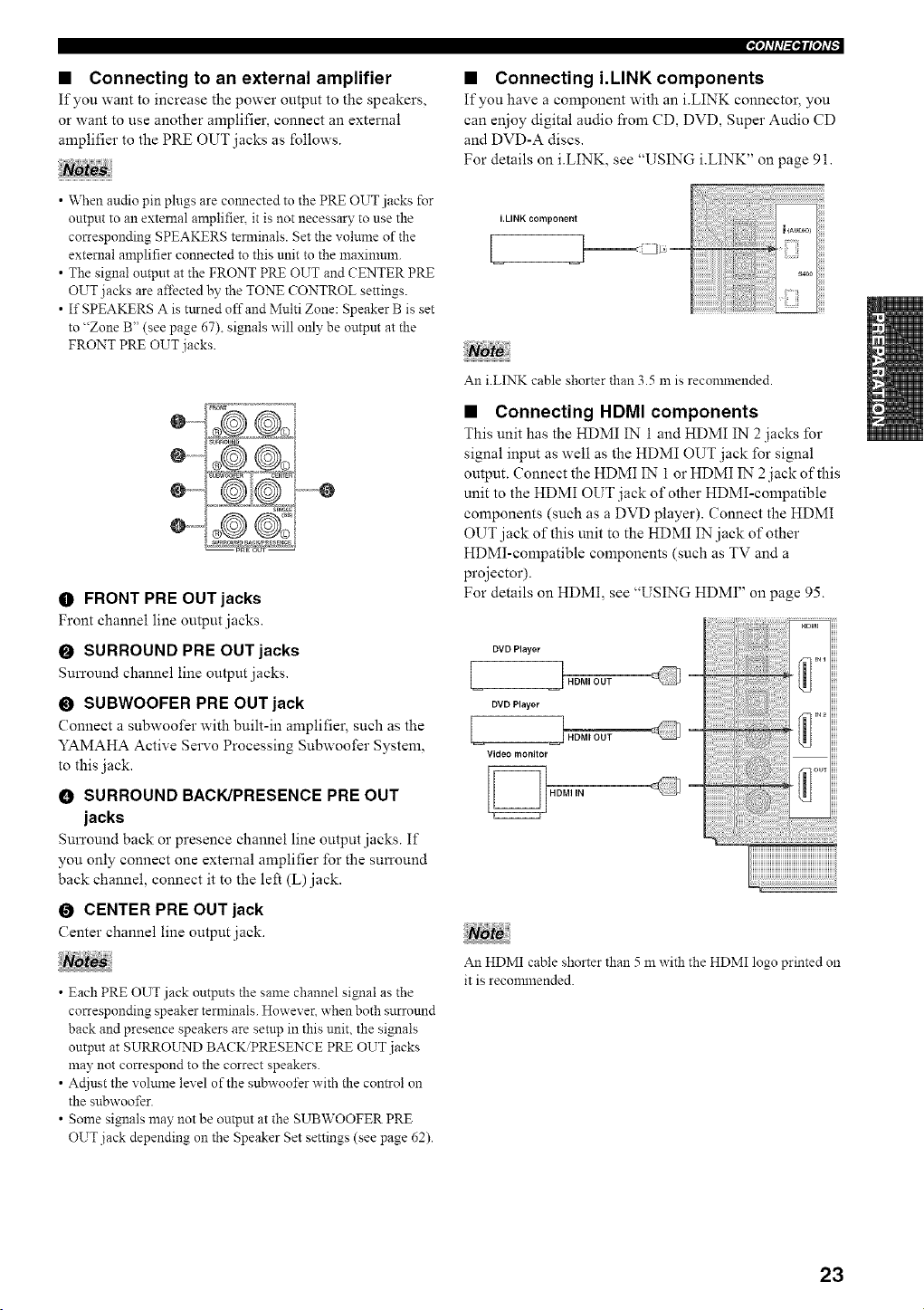
• Connecting to an external amplifier
If you want to increase the power output to the speakers,
or want to use another amplifier, connect an external
amplifier to the PRE OUT jacks as follows.
• When audio pin plugs are cmmected to the PRE OUT jacks for
output to an external amplifier, it is not necessary to use the
corresponding SPEAKERS terminals. Set the volume of the
external amplifier connected to this unit to the maxinmln.
• The signal output at the FRONT Pl_ OUT and CENTER PILE
OUT jacks are affected by the TONE CONTROL settings.
• If SPEAKERS A is turned off and Multi Zone: Speaker B is set
to "Zone B" (see page 67), signals will only be output at the
FRONT PILE OUT jacks.
_Rom
surround
0 .............
sJn_L_
_U_OUn_ae_P_ESE_¢E
O FRONT PRE OUT jacks
Front channel line output jacks.
O SURROUND PRE OUT jacks
Surround channel line output jacks.
• SUBWOOFER PRE OUT jack
Connect a subwoofer with built-in amplifier, such as the
YAMAHA Active Servo Processing Subwoofer System,
to this jack.
0 SURROUND BACK/PRESENCE PRE OUT
jacks
Surround back or presence channel line output jacks. If
you only connect one external amplifier for the surround
back channel, connect it to the left (L)jack.
O CENTER PRE OUT jack
Center channel line output jack.
• Each PRE OUT jack outputs the same channel signal as the
corresponding speaker terminals. However, when both surround
back and presence speakers are setup in this unit, the signals
output at SURROUND BA(KiPRESENCE PILE OUT jacks
may not correspond to the correct speakers.
• Adjust the volume level of the subwoofer with the control on
the subwoofer.
• Some signals may not be output at the SUBWOOFER PILE
OUT jack depending on the Speaker Set settings (see page 62).
• Connecting i.LINK components
If you have a component with an i.LINK connector, you
can enjoy digital audio from CD, DVD, Super Audio CD
and DVD-A discs.
For details on i.LINK, see "USING i.LINK" on page 91.
i.LINK component
[
An i.LINK cable shorter than 3.5 m is recomlnended.
• Connecting HDMI components
This unit has the HDMI IN 1 and HDMI IN 2 jacks for
signal input as well as the HDMI OUT jack for signal
output. Connect the HDMI IN 1 or HDMI 1N 2 jack of this
unit to the HDMI OUT jack of other HDMI-compatible
components (such as a DVD player). Connect the HDMI
OUT jack of this unit to the HDMI IN jack of other
HDMI-compatible components (such as TV and a
projector).
For details on HDMI, see "USING HDMI" on page 95.
[
DVD Player
] HDMI OUT
DVD Player
! HDM, OUT
Video monitor
An HDMI cable shorter than 5 m with the HDMI logo printed on
it is reconunended.
23
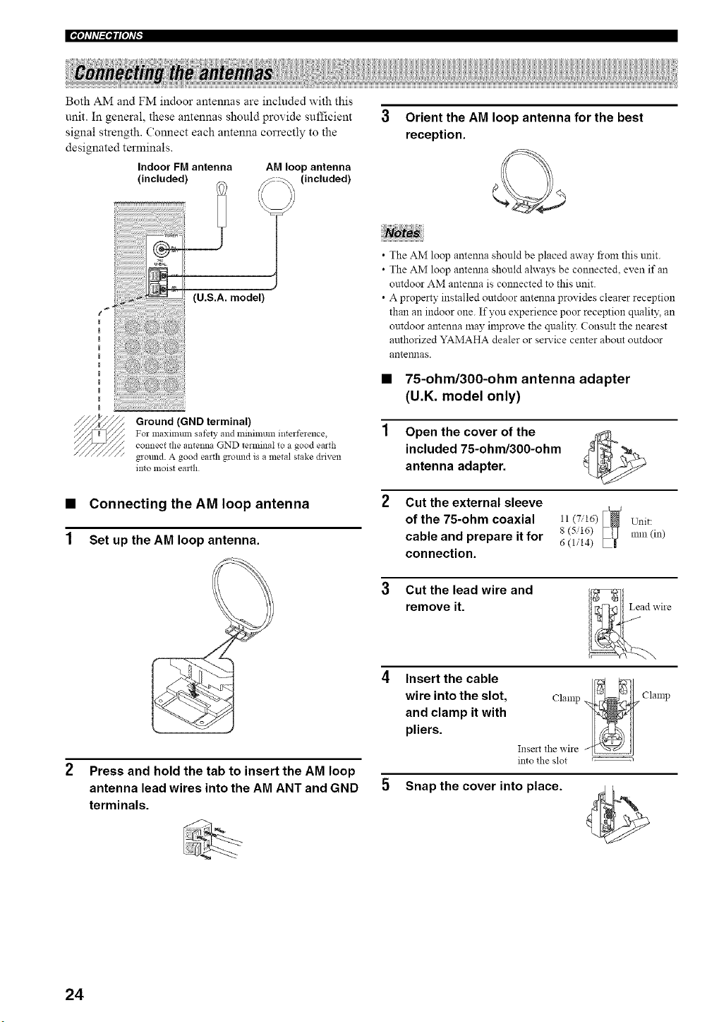
Both AM and FM indoor antennas are included with this
Indoor FM antenna
(included)
unit. In general, these antennas should provide sufficient
signal strength. Connect each antenna correctly to the
designated terminals.
AM loop antenna
(included)
t _
(U.S.A. model)
Ground(GNDterminal)
For maxilll/lm safety and llliIlimum interference
connect the antenna GND terminal to a good earth
ground. A good eartll ground is a metal stake driven
into moist earth
1
Connecting the AM loop antenna
Set up the AM loop antenna.
2 Press and hold the tab to insert the AM loop
antenna lead wires into the AM ANT and GND
terminals.
3 Orient the AM loop antenna for the best
reception.
• The AM loop antenna should be placed away from this unit.
• The AM loop antemla should ahvays be connected, even if an
outdoor AM antemla is connected to this unit.
• A property installed outdoor antenna provides clearer reception
than an indoor one. If you experience poor reception qnalit,,:an
outdoor antenna nlay improve the qualit3: Consult the nearest
authorized YAMAHA dealer or service center about outdoor
antelmas.
• 75-ohm/300-ohm antenna adapter
(U.K. model only)
Open the cover of the
included 75-ohm/300-ohm
antenna adapter.
Cut the external sleeve
I I
of the 75-ohm coaxial 11(7,,'16) _
8 (5/16)
cable and prepare it for 6(>'14)
connection.
Unit:
mm (in)
3 Cut the lead wire and
remove it.
viie
Insert the cable
wire into the slot,
and clamp it with
pliers.
Clamp._. Clamp
Insmtthe wire -'___" j
into the slot
Snap the cover into place.
24
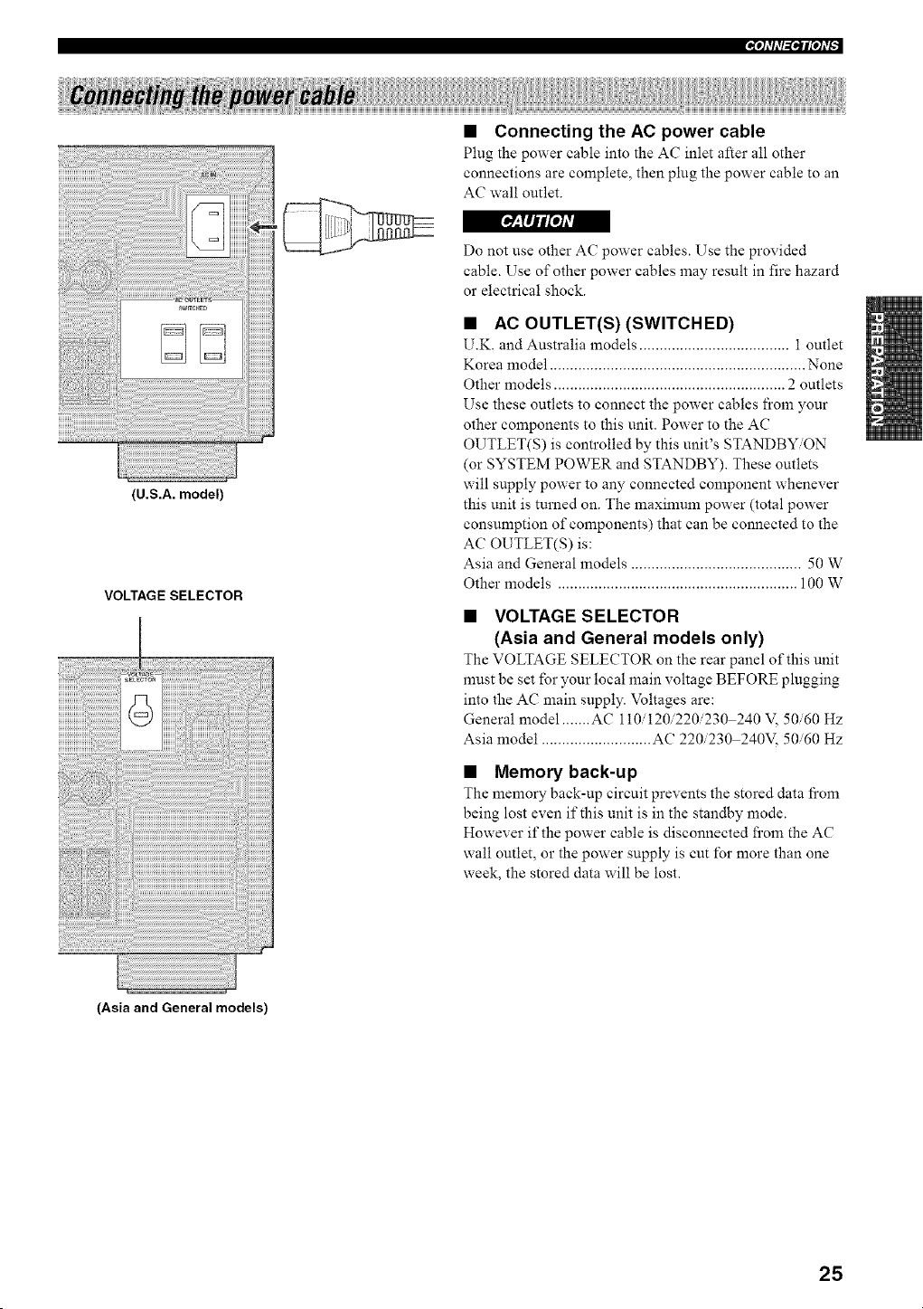
_°tfl_l_
• Connecting the AC power cable
Plug the power cable into the AC inlet after all other
connections are complete, then plug the power cable to an
AC wall outlet.
[_-'TIJil'o/#l
(U.S.A. model)
VOLTAGE SELECTOR
Do not use other AC power cables. Use the provided
cable. Use of other power cables may result in fire hazard
or electrical shock.
• AC OUTLET(S) (SWITCHED)
U.K. and Australia models ..................................... 1 outlet
Korea model ............................................................... None
Other models ......................................................... 2 outlets
Use these outlets to connect the power cables from your
other components to this unit. Power to the AC
OUTLET(S) is controlled by this unit's STANDBY/ON
(or SYSTEM POWER and STANDBY). These outlets
will supply power to any connected component whenever
this unit is turned on. The maximum power (total power
consumption of components) that can be connected to the
AC OUTLET(S) is:
Asia and General models .......................................... 50 W
Other models ........................................................... 100 W
• VOLTAGE SELECTOR
(Asia and General models only)
The VOLTAGE SELECTOR on the rear panel of this unit
must be set for your local main voltage BEFORE plugging
into the AC main supply. Voltages are:
General model ....... AC 110/120/220/230 240 V, 50/60 Hz
Asia model ........................... AC 220/230 240V, 50/60 Hz
• Memory back-up
The memory back-up circuit prevents the stored data fi'om
being lost even if this unit is in the standby mode.
However if the power cable is disconnected fi'om the AC
wall outlet, or the power supply is cut/'or more than one
week, the stored data will be lost.
(Asia and General models)
25
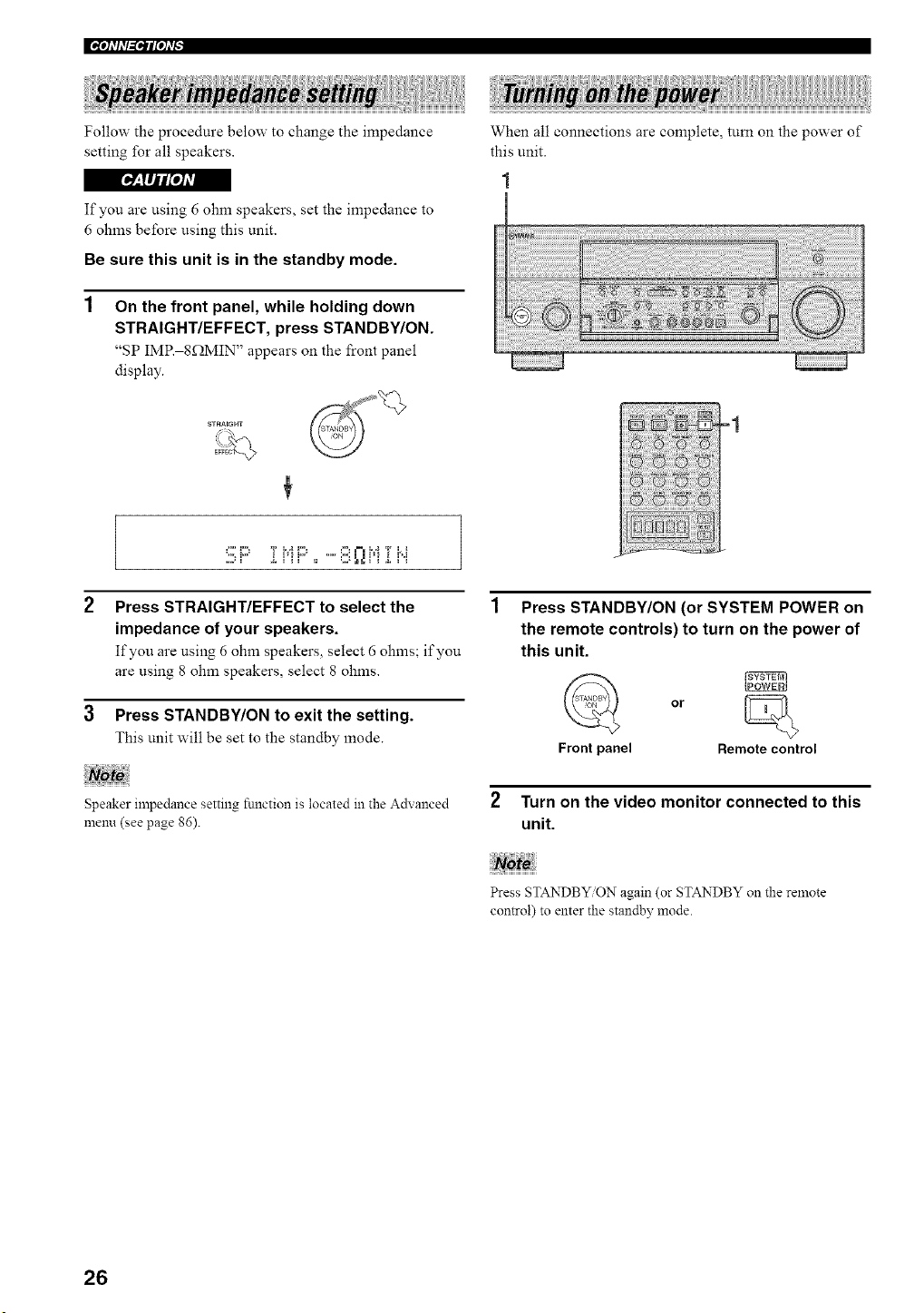
Follow the procedure below to change the impedance
setting for all speakers.
r_o,]__[Ijl[oIAvl
If you are using 6 ohm speakers, set the impedance to
6 ohms before using this unit.
Be sure this unit is in the standby mode.
On the front panel, while holding down
STRAIGHT/EFFECT, press STANDBY/ON.
"SP IMP. 8f2MIN" appears on the front panel
display.
When all connections are complete, turn on the power of
this unit.
STRAIGHT
:i!ilF' :[J"lJ:::',,' 8 QJfi:[J'.i
2 Press STRAIGHT/EFFECT to select the
impedance of your speakers.
If you are using 6 ohm speakers, select 6 ohms; if you
are using 8 ohm speakers, select 8 ohms.
3 Press STANDBY/ON to exit the setting.
This unit will be set to the standby mode.
Speaker impedance setting fnnction is located in the Advanced
menu (see page 86).
Press STANDBY/ON (or SYSTEM POWER on
the remote controls) to turn on the power of
this unit.
fyo_1
or
Front panel Remote control
2 Turn on the video monitor connected to this
unit.
Press STANDBY ON again (or STANDBY on the remote
control) to enter the standby mode.
26
iiil N ii iiI!i!iiii Ii!!i!iiiiU iii !!ii!!!ii!!!iii!!!iii!Iii i! ;iii!!i iH i! ;i!I
This receiver employs YAMAHA Parametric Room
Acoustic Optimizer (YPAO) technology which lets you
avoid troublesome listening-based speaker setup and
achieves highly accurate sound adjustments. The supplied
optimizer microphone collects and analyzes the sound
your speakers produce in your actual listening
environment.
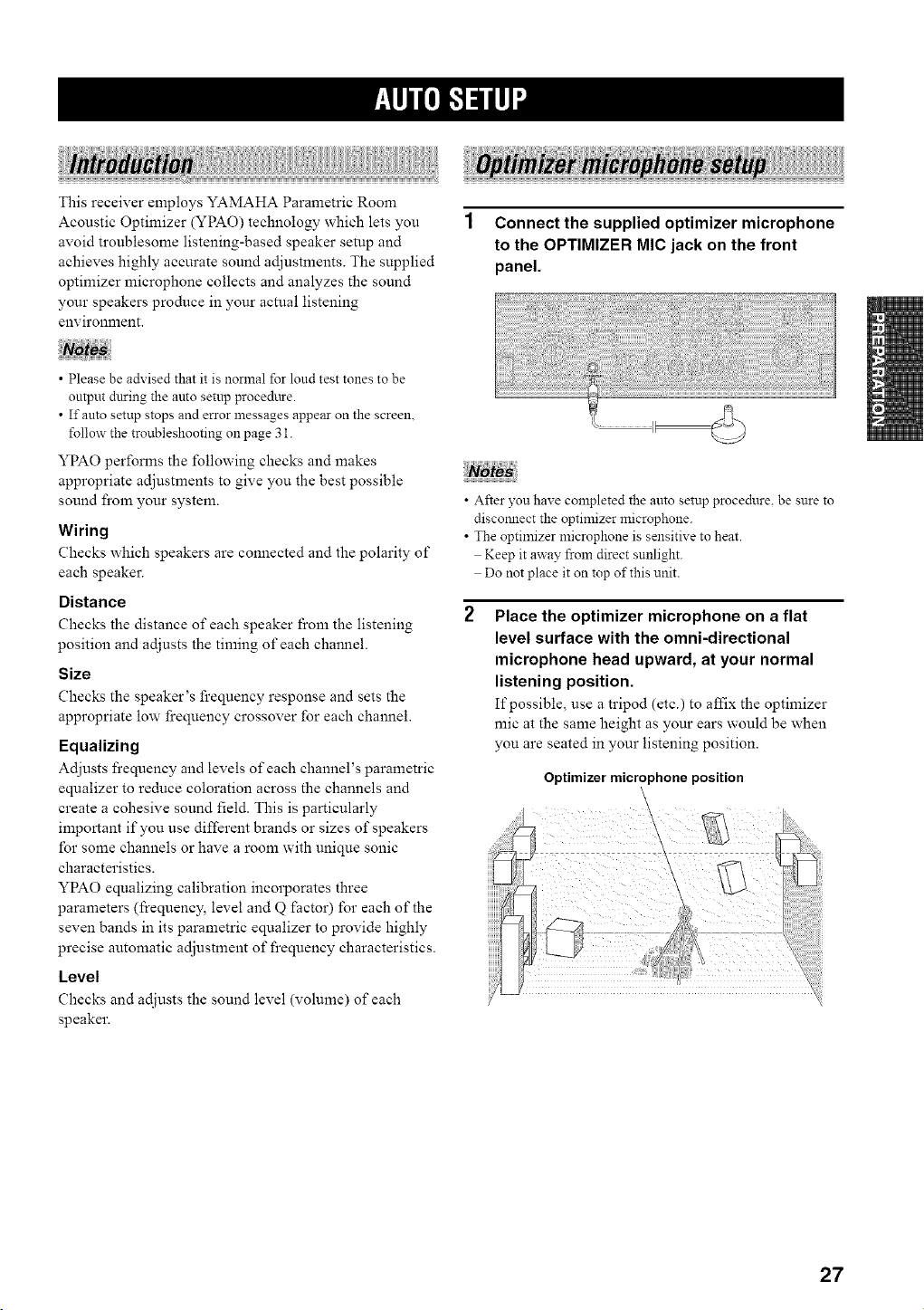
1 Connect the supplied optimizer microphone
to the OPTIMIZER MIC jack on the front
panel.
• Please be advised that it is normal for loud test tones to be
output chtring the auto setup procedttre.
• If auto setup stops and error messages appear on the screen.
follow the troubleshooting on page 31.
YPAO performs the following checks and makes
appropriate adjustments to give you the best possible
sound from your system.
Wiring
Checks which speakers are connected and the polarity of
each speaker.
Distance
Checks the distance of each speaker from the listening
position and adjusts the timing of each channel.
Size
Checks the speaker's frequency response and sets the
appropriate low frequency crossover for each channel.
Equalizing
Adjusts frequency and levels of each channel's parametric
equalizer to reduce coloration across the channels and
create a cohesive sound field. This is particularly
important if you use different brands or sizes of speakers
for some channels or have a room with unique sonic
characteristics.
YPAO equalizing calibration incorporates three
parmneters (frequency, level and Q factor) for each of the
seven bands in its parametric equalizer to provide highly
precise automatic adjustment of frequency characteristics.
Level
Checks and adjusts the sound level (volume) of each
speaker.
• After you have completed the auto setup procedure, be snre to
disconnect the optimizer microphone.
• The optimizer microphone is sensitive to heat.
Keep it away from direct sunlight.
Do not place it on top of this unit.
Place the optimizer microphone on a flat
level surface with the omni-directional
microphone head upward, at your normal
listening position.
If possible, use a tripod (etc.) to affix the optimizer
mic at the same height as your ears would be when
you are seated in your listening position.
Optimizer microphone position
\
27
l_lql,,pb,-ilq +
For best results, make sure the room is as quiet as possible
during the auto setup procedure (YPAO). If there is too
nmch ambient noise, the results may not be satisfactol 7.
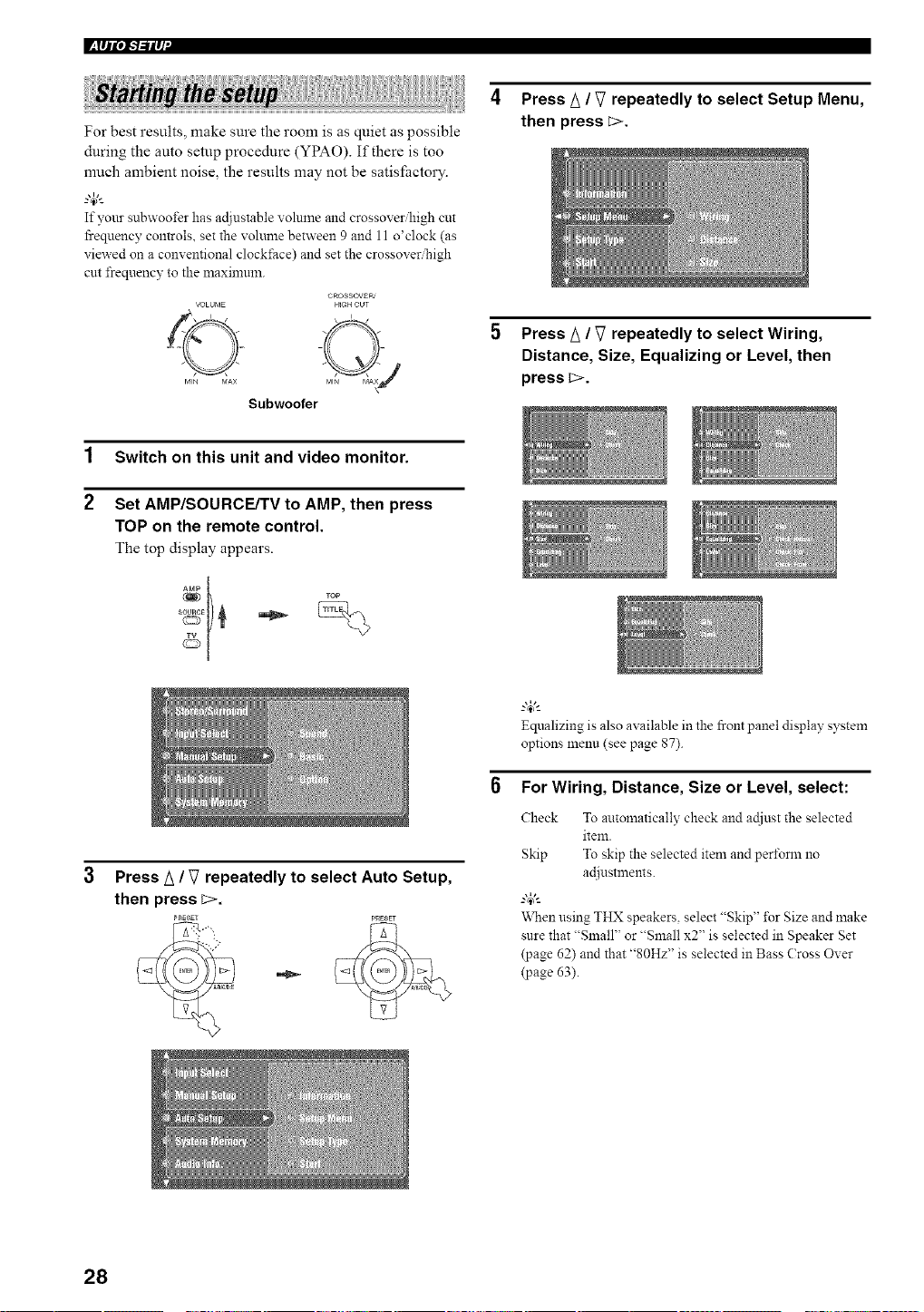
If your subwoofer has adjustable volume and crossove_high cut
frequency controls, set the volume between 9 and 11 o'clock (as
viewed on a conventional clockNce) and set the crossover_igh
cut frequency to the maximum+
VOLUME
MIN bIAX
Subwoofer
CROSSOVERt
HIGH CUT
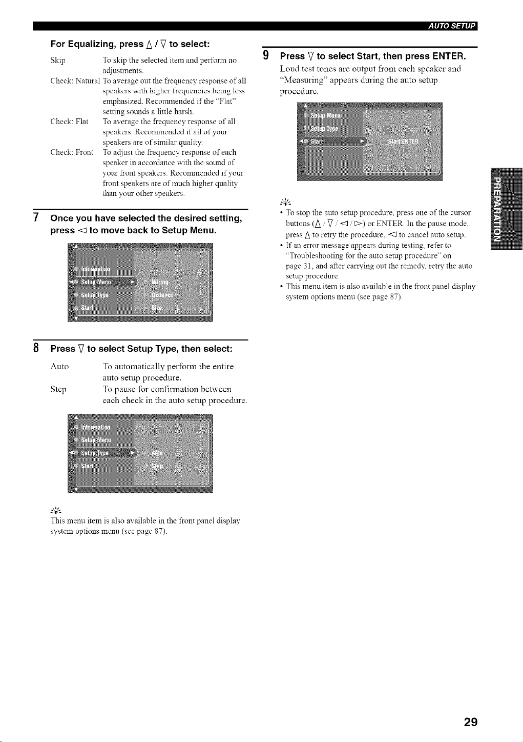
4 Press A / V repeatedly to select Setup Menu,
then press E>.
5 Press A / V repeatedly to select Wiring,
Distance, Size, Equalizing or Level, then
press c>.
1
2
Switch on this unit and video monitor.
Set AMP/SOURCE/TV to AMP, then press
TOP on the remote control.
The top display appears.
+
+1
3 Press A / V repeatedly to select Auto Setup,
then press L>.
PRESET P_ESET
Equalizing is also axailable in the front panel display system
options menu (see page 87).
For Wiring, Distance, Size or Level, select:
Check To atttomatically check and actjust the selected
item.
Skip To skip the selected item and perform no
ac[iustn'lent s+
'&'hen using THX speakers, select "Skip" %r Size and make
sure that "Small" or "Small x2" is selected in Speaker Set
(page 62) and that "80Hz" is selected in Bass (:ross Over
(page 63).
28
For Equalizing, press A / V to select:
Skip To skip the selected item and peri\mn no
adjnstments.
Check: Natural To average out the frequency response of all
speakers with higher frequencies being less
emphasized. Recommended if the "Flat"
setting sotmds a little harsh.
Check: Flat To average the frequency response of all
speakers. Reconm:ended if all of your
speakers are of similar qualit?:
Check: Front To actiust the frequency response of each
speaker in accordance with the somld of
your front speakers. Reconm:ended if your
front speakers are of much higher quality
than your other speakers.
Once you have selected the desired setting,
press <1 to move back to Setup Menu.
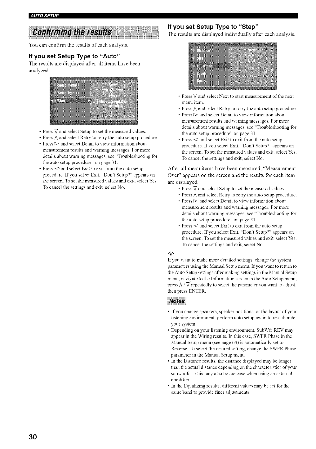
,lqP, l-'l-'ilq
Press V to select Start, then press ENTER.
Loud test tones are output from each speaker and
"Measuring" appears during the auto setup
procedure.
• To stop the auto setup procedure, press one of the cursor
buttons (A / :7 <1 / C>) or ENTER. In the pause mode,
press A to retD" the procedure, <:1 to cancel auto setup.
• If an error message appears during testing, refer to
"Troubleshooting for the auto setup procedure" on
page 3t. and after carrying out the remedy, retry the auto
setup procedure.
• This menu item is also available in the front panel display
system options menn (see page 87).
8 Press V to select Setup Type, then select:
Auto
Step
To automatically perform the entire
auto setup procedure.
To pause for confirmation between
each check in the auto setup procedure.
This menu item is also available in the front panel display
system options menu (see page 87).
29
l_lql',l-'l-'il q +
++ +++i + +
You can confirm the results of each analysis.
If you set Setup Type to "Auto"
The results are displayed after all items have been
analyzed.
If you set Setup Type to "Step"
The results are displayed individually after each analysis.
• Press _7 and select Setup to set the measured values.
• Press A and select Ret_" to retry the auto setup procedure.
• Press i> and select Detail to view inforlnation about
measurement results and warning messages. For more
details about warning messages, see "Troubleshooting _\_r
the auto setup procedure" on page 31.
• Press <1 and select Exit to exit from the amo setup
procedure. If you select Exit, "Don't Setup?" appears on
the screen. To set the measured values and exit, select Yes.
To cancel the settings and exit, select No.
• Press V and select Next to start measurement of the next
menu item.
• Press A and select Retry to retry the auto setup procedttre.
• Press C> and select Detail to view in_\_rmation about
measurement results and warning messages. For n'lore
details abom warning messages, see "Troubleshooting _\_r
the auto setup proce&tre" on page 31.
• Press <1 and select Exit to exit from the auto setup
procedure. If you select ExiL "Don't Setup?" appears on
the screen. To set the measured values and exit, select Yes.
To cancel the settings and exit. select No.
After all menu items have been measured, "Measurement
Over" appears on the screen and the results for each item
are displayed.
• Press V and select Setup to set the measured values.
• Press _ and select Retry to retry the attto setup procedure.
• Press C> and select Detail to view inI\_rmation about
lneasurement results and warning messages. For n'lore
details about warning messages, see "Troubleshooting I\_r
the auto setup proce&tre" on page 31.
• Press <1 and select Exit to exit from the auto setup
procedure. If you select Exit. "Don't Setup?" appears on
the screen. To set the measured values and exit, select Yes.
To cancel the settings and exit. select No.
_.,#._
If you want to make more detailed settings, change the system
parameters using the Manual Setup menu. If you want to return to
the Auto Setup settings after making settings in the Manual Setup
menu. navigate to the Information screen in the Auto Setup menu,
press _ / _7repeatedly to select the parameter you want to acliust,
then press ENTER.
• If you change speakers, speaker positions, or the layout of your
listening environment, perform auto setup again to re-calibrate
your system.
• Depending on yottr listening environment, SubWfr:REV may
appear in the Wiring results. In this case, SWFR Phase in the
Manual Setup menu (see page 64) is automatically set to
Reverse. To select the desired setting, change the SWFR Phase
parameter in the Manual Setup menu.
• In the Distance results, the distance displayed may be longer
than the actual distancedepending on the characteristics of your
subwoofer. This may also be the case when using an external
amplifier.
• In the Equalizing results, different values may be set for the
same band to provide finer ac[iUStlnents.
3O
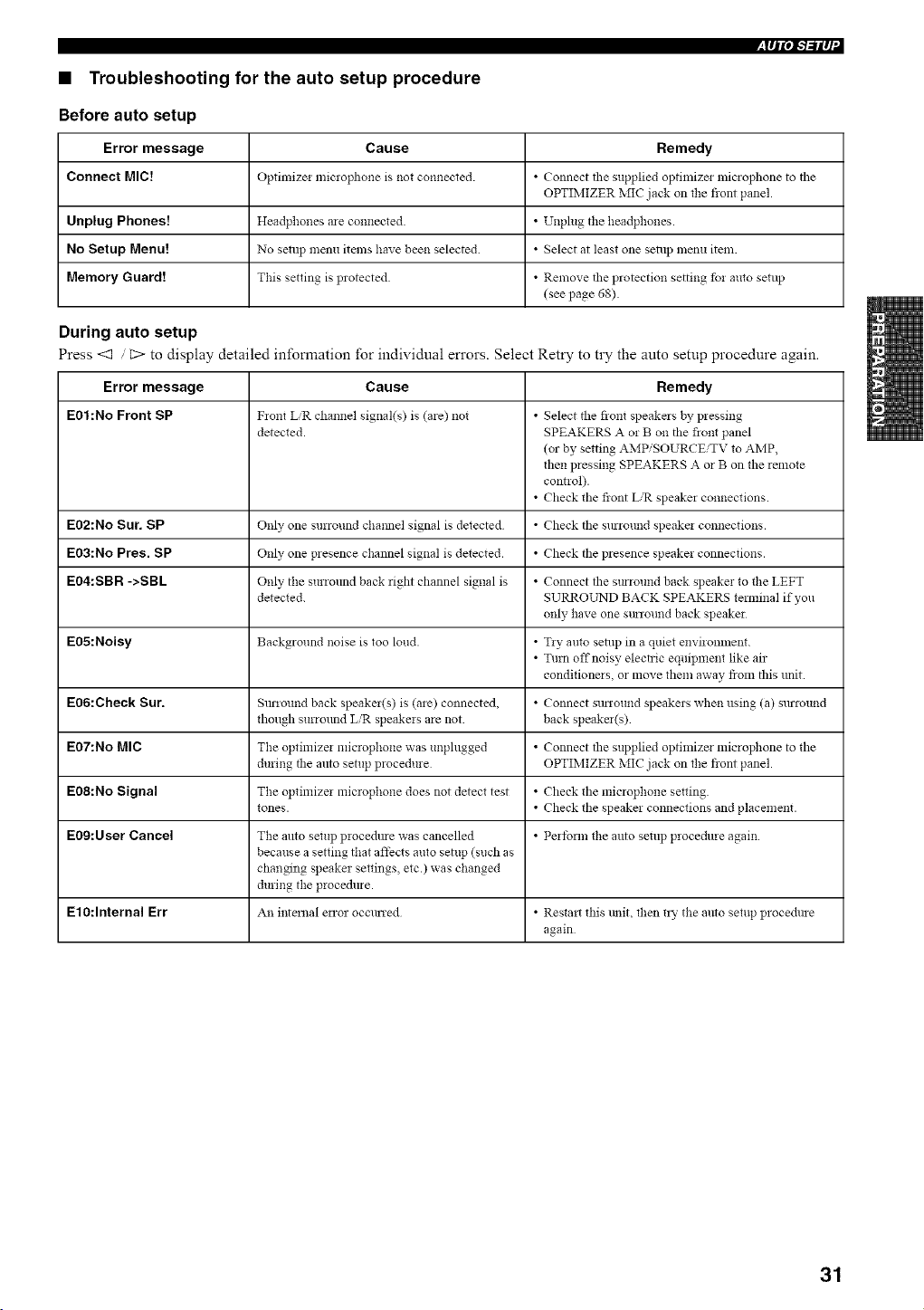
,lll|°IFbilq
• Troubleshooting for the auto setup procedure
Before auto setup
Error message Cause Remedy
Connect MIC[ Optimize! microphone is not connected. • Connect the supplied optimizer lnicrophone to the
OPTIMIZER MIC jack on the flont panel.
Unplug Phones7 Headphones are connected. • Unplug the headphones.
No Setup Menu! No setup menu items have been selected. • Select at least one setup menu item.
Memory Guard! This setting is protected • Remove tile protection setting fbr auto setup
(see page 68).
During auto setup
Press <1 C> to display detailed information for individual errors. Select Retry to try the auto setup procedure again.
Error message Cause Remedy
E0t :No Front SP F_ont LR channel signal(s) is (are) not • Select tile front speakers by pressing
detected. SPEAKERS A or B on tile flont panel
(or by setting AMPiSOURCEiTV to AMP,
then pressing SPEAKERS A or B on the remote
control).
• Check the front LiR speaker connections.
E02:No Sur. SP Only one surround chmmel signal is detected • Check tile surround speaka connections.
E03:No Pres. SP Only one p_esence channel signal is detected. • Check tile presence speaker connections.
E04:SBR ->SBL Only tile surround back right channel signal is • Connect tile SmTound back speaker to tile LEFT
detected. SURROL2qD BACK SPEAKERS temfinal if you
only have one smround back speaker
E05:Noisy Background noise is too loud. • Tly auto senlp in a quiet environment.
• Turn offnoisy electric equipment like air
conditionels, or move them away from this unit.
E06:Check Sur. Smaound back speaker(s) is (are) connected, • Connect SUlTOUndspeakers when using (a) surround
though surround LiR speakers are not back speaka(s)
E07:No MIC The optimizer microphone was unplugged • Connect tile supplied optimizer microphone to the
during tile anto setup procedure OPTIMIZER MIC jack on the flont panel.
E08:No Signal The optimizer microphone does not detect test • Check the microphone setting.
tones. • Check the speaker connections and placement.
E09:User Cancel The anto setup procedme was cancelled • Pertbnn tile anto setup procedure again.
because a setting that afthcts auto setup (such as
changing speaker settings, etc.) was changed
during the procedure.
E10:lnternal Err An flltemal error occmTed • Restart this lmit, then try the anto setup procedure
again
31
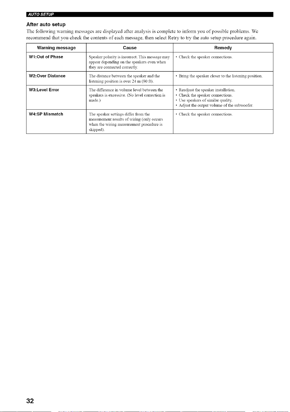
I_Fil0/-l-'ilq`
After auto setup
The following warning messages are displayed after analysis is complete to mfonn you of possible problems. We
recommend that you check the contents of each message, then select Retry to try the auto setup procedure again.
Warning message Cause Remedy
Wl :Out of Phase Speaker polarity is inconect. This message may • Check the speake_ connections.
appear depending on the speakers even when
they are connected conectly
W2:Over Distance The distance between the speaker and the • Bring the speaker closes to the listening position.
listening position is over 24 m (80 fl).
W3:Level Error The difference in volulne level between the • Readjust the speaker installation.
speakers is excessive. (No level conection is • Check the speaker connections.
made) • Use speakers of similar quality.
• Adjust the output volume of the subwoofbr.
W4:SP Mismatch The speaker settings differ from the • Check the speaka connections.
measttl ement results of wiring (only occurs
when the wiring measurement proce&_re is
skipped).
32
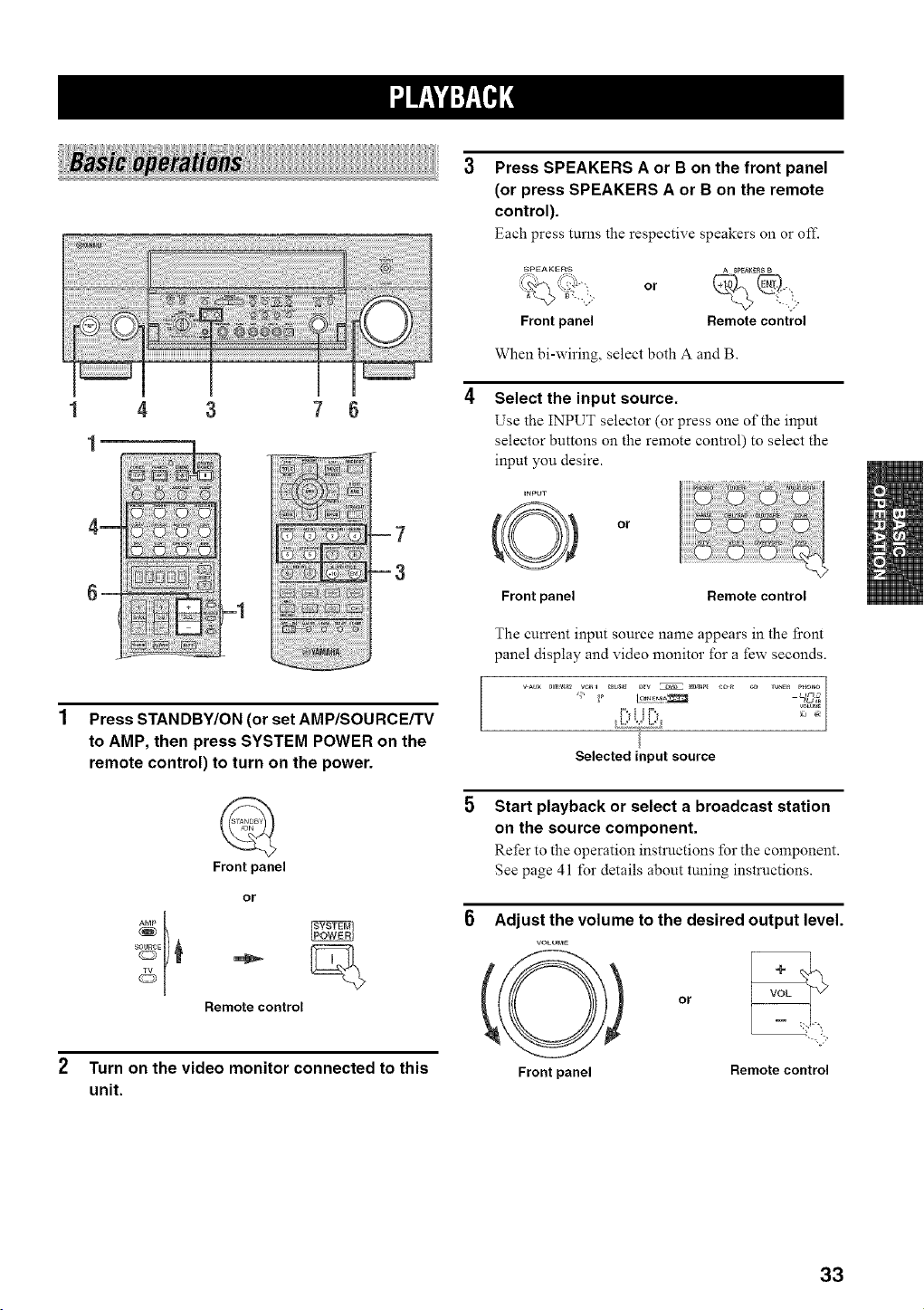
_|||{i||||;;|;|;|;|;|;|i;ii|||;i|||
m
__
4 3
-1
7 6
Press STANDBY/ON (or set AMP/SOURCE/TV
to AMP, then press SYSTEM POWER on the
remote control) to turn on the power.
AMP
Front panel
or
Remote control
Turn on the video monitor connected to this
unit.
Press SPEAKERS A or B on the front panel
(or press SPEAKERS A or B on the remote
control).
Each press turns the respective speakers on or off.
_'EA KERS A SPEA_E_$ B
%®!
:_ ' ' _ _4-", or
Front panel Remote control
When bi-wiring, select both A and B.
Select the input source.
Use the INPUT selector (or press one of the input
selector buttons on the remote control) to select the
input you desire.
Front panel Remote control
The current input source name appears in the fi'ont
panel display and video monitor for a few seconds.
3
I,,'_2.22,2L |
Selected input source
Start playback or select a broadcast station
on the source component.
Refer to the operation instructions for the component.
See page 41 for details about tuning instructions.
Adjust the volume to the desired output level.
VOLO_E
Front panel
or
Remotecontrol
33
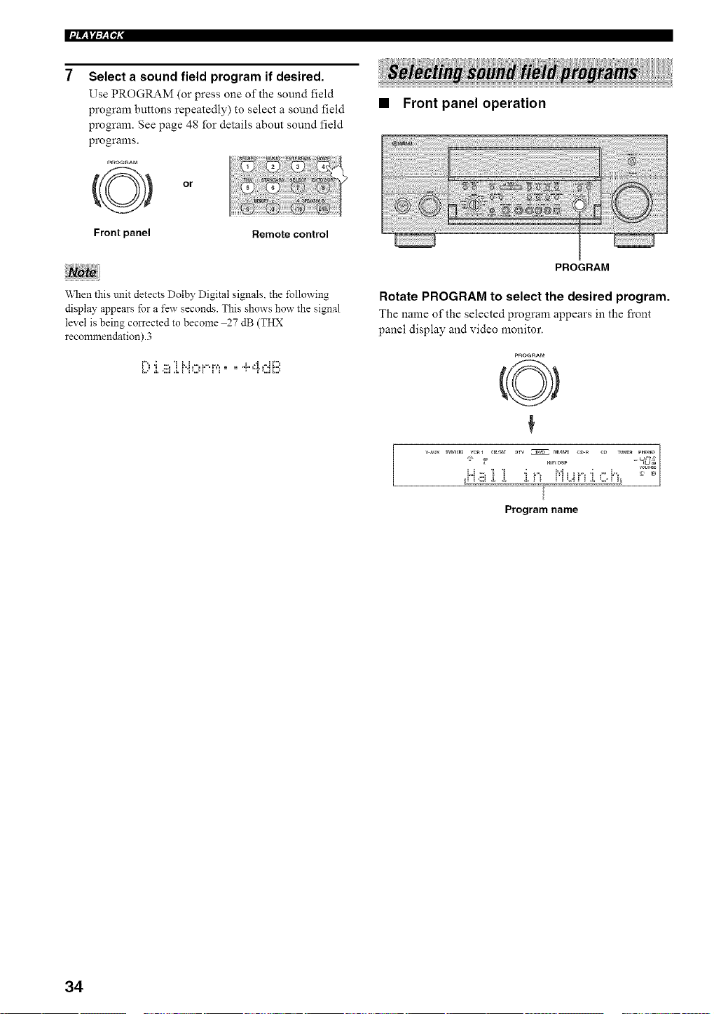
Select a sound field program if desired.
Use PROGRAM (or press one of the sound field
program buttons repeatedly) to select a sound field
program. See page 48 for details about sound field
programs.
Front panel Remote control
When this unit detects Dolby Digital signals, the following
display appears for a few seconds. This shows how the signal
level is being corrected to become 27 dB (THX
recommendation) .3
L.." & ,:::! & ! "[k..= ! [" [ .... z "[. k..! !...=
• Front panel operation
PROGRAM
Rotate PROGRAM to select the desired program.
The name of the selected program appears in the front
panel display and video monitor.
PROGRAM
O
Hiri DsP - C_C_dB
/
Program name
34
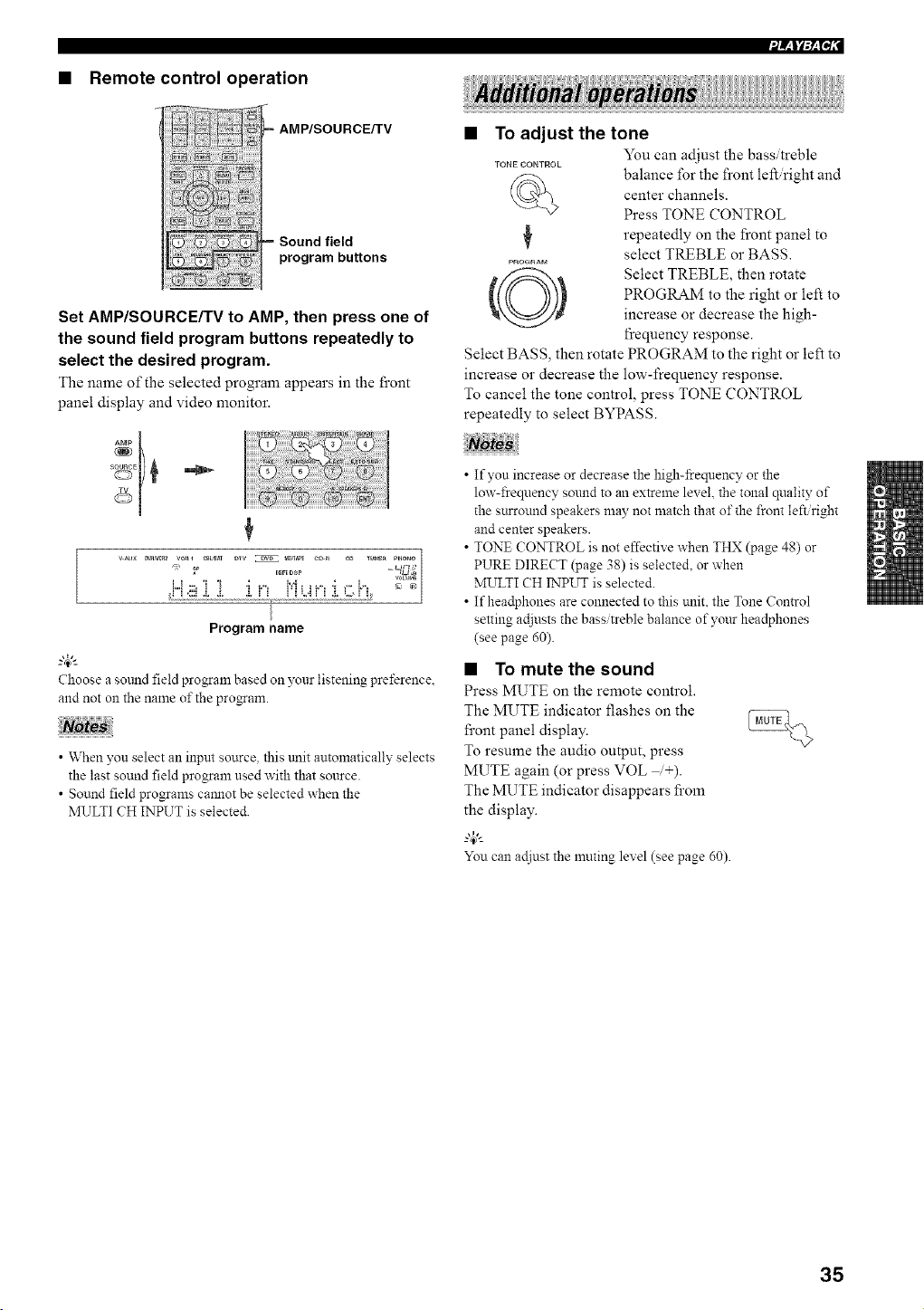
• Remote control operation
,AMP/SOURCEKV
Sound field
program buttons
Set AMP/SOURCE/TV to AMP, then press one of
the sound field program buttons repeatedly to
select the desired program.
The name of the selected program appears in the front
panel display and video monitor.
7
VAL_× DV_,_2 ve_l _BU_ DTV _ t_,_ C_ _D TU_ER PNONO|
Hiri DSP C_tJ_
/
/
Program name
_.,#._
Choose a sotmd field program based on your listening preference.
and not on the name of the pro_am.
• When you select an input source, this trait automatically selects
the last sound field program used with that source.
• Sound field programs cannot be selected when the
MULTI CH INPUT is selected.
• To adjust the tone
TONE CONTROL
Q
PRO_RAr_
You can adjust the bass/treble
balance for the front left.right and
center channels.
Press TONE CONTROL
repeatedly on the front panel to
select TREBLE or BASS.
Select TREBLE, then rotate
PROGRAM to the right or left to
increase or decrease the high-
frequency response.
Select BASS, then rotate PROGRAM to the right or left to
increase or decrease the low-frequency response.
To cancel the tone control, press TONE CONTROL
repeatedly to select BYPASS.
• If you increase or decrease the high-frequency or the
low-freqnency sound to an extreme level, the tonal quality of
the surround speakers may not match that of the front left/right
and center speakers.
• TONE CONTROL is not effective when THX (page 48) or
PURE DIRECT (page 38) is selected, or when
MULTI (H INPUT is selected.
• If headphones are connected to this unit. the Tone Control
setting adjusts the bass/treble balance of your headphones
(see page 60).
• To mute the sound
Press MUTE on the remote control.
The MUTE indicator flashes on the
front panel display.
To resume the audio output, press
MUTE again (or press VOL _+).
The MUTE indicator disappears from
the display.
You can ac[iust the muting level (see page 60).
35
l['ill:_lq,
• To listen with headphones
("SILENT CINEMA")
"SILENT CINEMA" allows you to enjoy multilchannel
nmsic or movie sound, including Dolby Digital and DTS
surround, through ordinary headphones. "SILENT
CINEMA" activates automatically whenever you connect
headphones to the PHONES jack while listening to
CINEMA DSP or HiFi DSP sound field programs. When
activated, the "SILENT CINEMA" indicator lights up in
the front panel display.
• This unit will not be set to "SILENT CINEMA" when
MULTI CH INPUT is selected as the input source.
• "SILENT CINEMA" is not effective when PURE DIRECT or a
2ch Stereo program is selected, or in STRAIGHT mode.
• Selecting the MULTI CH INPUT
Press MULTI CH INPUT so that "MULTI CH INPUT"
appears m the front panel display and video monitor.
MULTICH
INPUT
Front panel
or
MULTI(;H IN
Remote control
HULII CH ]:NPUT
\_llen "MULTI CH INPUT" is shown on the front panel display
and/or the video monitor, no other source can be played. To select
another input source with the INPUT selector on the front panel
(or one of the input selector buttons on the remote control), press
MULTI CH INPUT to turn off"MULTI CH INPUT" from the
front panel display and the video monitor.
• Enjoying multi-channel software in
6.1/7.1 channel surround
If you connected one or two sun'ound back speakers, use
this feature to enjoy 6.1/7.1 -channel playback for
multi-channel sources using the Dolby Pro Logic fix,
Dolby Digital EX or DTS-ES decoders.
Set AMP/SOURCE/TV to AMP, then press EXTD
SUR. on the remote control to switch between 5.1
and 6.1/7.1 channel playback.
To select a decoder, press <l / _> repeatedly
when PLJ[ixMovie (etc.) is displayed.
Auto (l:ii...i']"l])
When a signal (flag) that can be recognized by the unit is
input, the unit selects the optimum decoder for playing
back the signal in 6.1/7.1 channels.
If the unit cannot recognize the flag or no flag is present in
the input signal, it cannot automatically be played in
6.1/7.1 channels.
Decoders (select with <1 / E>)
You can select from the following modes depending on
the format of the software you are playing.
F ) L. i[[ )':: i'[i Cl 1...1 j, 1_1
For playing back Dolby Digital or DTS signals in 7.1
channels using the Pro Logic Hx movie decoder.
F::i....Z[:Wk..i!i.:i.,:::.
For playing back Dolby Digital or DTS signals in 6.17.1
channels using the Pro Logic [Ix nmsic decoder.
F=X/ i:::,:::;
For playing back Dolby Digital signals in 6.1 7.1 channels
using the Dolby Digital EX decoder.
DTS signals are played back in 6.17.1 channels using the
DTS-ES decoder.
F_X
For playing back Dolby Digital or DTS signals in 6.17.1
channels using the Dolby Digital EX decoder.
Off (l]F:'l:::')
For playing back Dolby Digital or DTS signals in 5.1
channels.
-4::
"_\NenSurround Back is set to "Large xl" or "Small xl"
(see page 63), the surround back chmmel will output from the left
SURROUND BACK speaker terminals.
36
• Some 6.1-channel compatible discs do not have a signal (flag)
which this unit can automatically detect. When playing these
kinds of discs with 6.1-chalmel. select decoders (PLHxMovie.
PLl]xMusic, EXiES or EX) mannall?_
• 6.1/7. l-channel playback is not possible even if EXTD SUR. is
pressed in the following cases:
\_]len Surround or Surround Back is set to "None"
(see page 63).
\_]len the source connected to the MULTI CH INPUT jack is
being played.
When the source being played does not contain surround LiR
chamlel signals.
When a Dolby Digital KARAOKE soarce is being played.
When 2ch Stereo. 7ch Stereo or PURE DIRECT is selected.
• When the power of this unit is turned off. the input mode will be
reset to AUTO.
• The Pro Logic llx decoder is not available when Snrround Back
is set to "None" (see page 63).
• "PMlxMovie" cmmot be selected when Snrround Back is set to
"Large xl" or "Small xl" (see page 63).
• Enjoying 2-channel software in surround
Signals input Ii'om 2-channel sources can also be played
back on multiple channels.
Set AMP/SOURCE/TV to AMP, then press
STANDARD on the remote control to switch
between the SUR. STANDARD and SUR.
ENHANCED programs.
Or press MOVIE or THX on the remote control to
select the MOVIE THEATER or THX programs.
MOWE "rH×
or
Press SELECT on the remote control to select
the decoder.
.qELECT
You can select from the following modes depending on
the type of software you are playing and your personal
preference.
When you select the SUR. STANDARD program
Dolby Pro Logic processing lbr any sources.
Dolby Pro Logic [Ix processing lbr movie software.
•::Ii:::'L"i>:.::i"i_...i:il;.:i.,:::.i::'
Dolby Pro Logic lIx processing for music software.
..._ _.."iT':.(l.::i._ii!i'q,ii_,.::'
Dolby Pro Logic [Ix processing for game software.
•::bh::_¢'HlI:..,I: "li.%:_r,'_:::_?.
DTS processing for movie software.
DTS processing for music software.
•::'I":':::;'i°i l":'ii._.::=r,',:::,'?.*
SRS Circle Surround II processing lbr movie software.
.." _"',::;= 'i"r i"ii i" '; _" ''_
SRS Circle Surround [I processing for nmsic software.
• (U.S.A. model only)
When you select the SUR. ENHANCED, MOVIE
THEATER or THX programs
.." _1::,i::)=% i ¢"H'::: T ¢" '..
Dolby Pro Logic processing for any sources.
%11 ................
Dolby Pro Logic ]fix processing lbr movie software.
•::I".I_::_='_II 1=', I: I i.%:_r,'.:::_;:.
DTS processing for movie software.
g4_'--
• Yon can also select a decoder with the Decode Type parameter
in the Stereo Surround menu (see page 99).
• Yon can also select a decoder by pressing <1 t:> on the remote
control when the decoder t??e is displayed in the short message
display.
The Pro Logic llx decoder is not axailable when Surromld Back is
set to "None" (see page 63).
37
l[Will;_N,
• Listening to high fidelity stereo sound
(PURE DIRECT)
PURE DIRECT bypasses this unit's decoders and DSP
processors as well as shuts down the video circuitry,
allowing you to enjoy the highest possible sound fidelity
from analog and PCM sources.
Press PURE DIRECT to activate pure direct.
The button lights up and the front panel display
automatically goes out.
Front panel
or
PU_E NI_ECT
Remote control
The front panel display switches on momentarily when an
operation is performed.
To cancel, press PURE DIRECT again.
The indicator around the front panel button goes out and
the previous settings are restored.
• To avoid unexpected noise, do not play DTS-encoded CDs in
this mode.
• When a lnulti-channel signal (Dolby Digital or DTS) is input,
this tmit automatically switches to the corresponding analog
input. (When DTS is selected as an input mode. no sound will
be heard.)
• No sound will be output from the subwoofer.
• Tone Control (page 35) and GUI menu (page 52) settings are
not effective.
• The t\_llowing operations are not possible during PURE
DIRECT operation:
switching the sound field program
displaying the short message
ac{iusting GUI menu parameters
all video ftmctions (video conversion etc.)
• PURE DIRECT is automatically cancelled whenever this unit is
set to the standby mode.
• Night listening modes
The night listening modes are designed to improve
listenability at lower volumes or at night. Choose either
NIGHT:CINEMA or NIGHT:MUSIC depending on the
type of material you are playing.
Set AMP/SOURCE/TV to AMP, then press NIGHT
on the remote control repeatedly to select
cinema or music.
When night listening is selected, the NIGHT indicator in
the front panel display lights up.
NIGHT
Remote control
• Select NIGHT:CINEMA when watching films to
reduce the dynamic range of fihn soundtracks and
make dialog easier to hear at lower volumes.
• Select NIGHT:MUSIC when listening to music sources
to presmwe ease-of-listening for all sounds.
• Select NIGHT:OFF if you do not want to use this
function.
Press <1 / [> to adjust the effect level while
NIGHT:CINEMA or NIGHT:MUSIC is displayed.
This adjusts the level of compression.
PnESET
Remote control
l"' I" I" ...... ,i, [ • ,'1 II l,,,i "i' l",,
l" T' T' l''= I , I , ,, l t, ,t I == I'I I l J
• Select "MIN" lbr minimum compression.
• Select "MID" for standard compression.
• Select "MAX" for maxinmm compression.
_%,._
NIGHT:CINEMA and NIGHT:MUSIC ac{iustments are stored
independently.
• You cannot use the night listening modes with PURE DIRECT.
MULTI CH INPUT, or when headphones are connected
(even though the NIGHT indicator lights up when PURE
DIRECT is selected).
• The night listening modes may vao" in effectiveness depending
on the input source and surround sound settings you use.
38
• Downmixing to 2 channels
You can enjoy 2-channel stereo playback from nmlti-
channel sources.
Rotate PROGRAM (or set AMP/SOURCE/TV to
AMP, then press STEREO on the remote control)
to select 2ch Stereo.
PROGRAM
Front panel
or
Remote control
% .., L, _"'=.E............
• Playing video sources in the
background
You can combine images fi'om a video source with sound
fi'om an audio source. For example, you can enjoy
listening to classical music while having beautiful scenery
fi'om the video source on the video monitor.
Use the input selector buttons to select a video
source, then select an audio source.
.......................................Audio sources
:.... / Videosources
You can use a subwoofer with this pro_am when SWFR or
BOTH is selected in LFE BASS OUT.
• Listening to unprocessed input signals
In STRAIGHT mode, two channel stereo sources are
output fi'om only the front left and right speakers. Multi-
channel sources are decoded straight into the appropriate
channels without any additional effect processing.
Press STRAIGHT (EFFECT) to select STRAIGHT.
STRAIGHT
E_F_CT
Front panel Remote control
=_" "_" ,'=%=% "r ==" i i "=_
2, i P:, P{ ,L12ii'i i
Press STRAIGHT.EFFECT again so that "STRAIGHT"
disappears fi'om the display when you want to turn the
sound effect back on.
• Virtual CINEMA DSP
Virtual CINEMA DSP allows you to enjoy the CINEMA
DSP programs without sun'ound speakers. It creates
virtual speakers to reproduce a natural sound field.
If you set Surround to None, Virtual CINEMA DSP
activates automatically whenever you select a CINEMA
DSP sound field progrmn.
If you want to enjoy an audio source connected to the
MULTI CH INPUT jacks together with a xideo source, first select
the video source and then press MULTI CH INPUT.
Virtual CINEMA DSP will not activate, even when Surround is
set to "None" (see page 62) in the following cases:
\_]len MULTI CH INPUT is selected as the input source.
When headphones are connected to the PHONES jack.
39
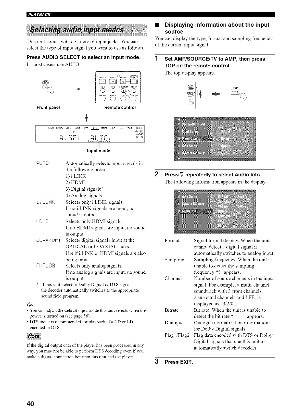
This unit comes with a variety of input jacks. You can
select the type of input signal you want to use as follows.
Press AUDIO SELECT to select an input mode.
In most cases, use AUTO.
_mlo
SELECT
A= ' E) AU_0SEtEe_
PHONO TUNES eO IJCm_
Front panel Remote control
+
v_ux _ v¢_1 cDus_ DTV DW MNAPE ¢_g eD lU_E_ PHONO
Input mode
l"ll...'l''lir'i"l"l++...l Automatically selects input signals in
the following order:
i) i.EINK
2) HDMI
3) Digital signals*
4) Analog signals
•; i T i..ii .... Selects only i.EINK signals.
,L 1: L,,, ,L I 'II'.<
If no i.EINK signals are input, no
sound is output.
lL'ii%i',t::.rl<: _lIT Selects only HDMI signals.
If no HDMI signals are input, no sound
is output.
,....,...,r..,+..:..;"'"+"';+":""+'i::'+i",...,:: Selects digital signals input at the
OPTICAL or COAXIAL jacks.
Use ifi.LINK or HDMI signals are also
being input.
l"li"il"li+"ll':) Selects only analog signals.
If no analog signals are input, no sound
is output.
• If this unit detects a Dolby Digital or DTS signal.
the decoder automatically switches to the appropriate
sound field program.
• You can at[just the det;ault input mode this unit selects when the
power is turned on (see page 56).
• DTS mode is reconnnended %r playback of a CD or LD
encoded in DTS.
If the digital output data of the player has been processed in any
way you may not be able to perform DTS decoding exen if you
make a digital connection between this unit and the player.
• Displaying information about the input
source
You can display the type, _bnnat and sampling fi+equency
of the current input signal.
Set AMP/SOURCE/TV to AMP, then press
TOP on the remote control.
The top display appears.
+[
+
+l
2 Press V repeatedly to select Audio Info.
The following information appears in the display.
Format
Sampling
Channel
Bitrate
Dialogue
Flagl Flag2
Signal format display. When the unit
cannot detect a digital signal it
automatically switches to analog input.
Sampling frequency. When the unit is
unable to detect the sampling
frequency "?" appears.
Number of source channels in the input
signal. For example, a multi-channel
soundtrack with 3 front channels,
2 sun'ound channels and LFE, is
displayed as "3/2/0.1".
Bit rate. When the unit is unable to
detect the bit rate .... appears.
Dialogue normalization in_brmation
for Dolby Digital signals.
Flag data encoded with DTS or Dolby
Digital signals that cue this unit to
automatically switch decoders.
3 Press EXIT.
40
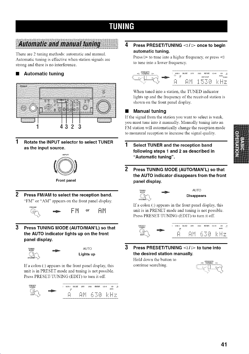
There are 2 tuning methods: automatic and manual.
Automatic tuning is elTective when station signals are
strong and there is no interference.
• Automatic tuning
1 4323
Rotate the INPUT selector to select TUNER
as the input source.
=nPuv
Front panel
Press FM/AM to select the reception band.
"FM" or "AM" appears on the front panel display.
:="= _ F 1'i or M I'1
:.%
Press TUNING MODE (AUTO/MAN'L) so that
the AUTO indicator lights up on the front
panel display.
,_u.._ AUTO
_: Lights up
Ifa colon (:) appears in the front panel display, this
unit is in PRESET mode and tuning is not possible.
Press PRESET TUNING (EDIT) to turn it off.
PRESET_
TUNI_ _ WR_ _m,S_ DrY DVD t_0,_P_ _D_ eD
Press PRESET/TUNING <1 / c> once to begin
automatic tuning.
Press C> to tune into a higher frequency, or press <1
to tune into a lower frequency.
PnESEW
<J TUN_N_ C:> _ ve_ 1 _B_T DtV DVD mD,_PE CD _ e_
r"_ idr i i h,':, i,i k' H 7
When tuned into a station, the TUNED indicator
lights up and the frequency of the received station is
shown on the front panel display.
• Manual tuning
If the signal from the station you want to select is weak,
you must rune into it manually. Manually tuning into an
FM station will automatically change the reception mode
to monaural reception to increase the signal quality.
1 Select TUNER and the reception band
following steps 1 and 2 as described in
"Automatic tuning".
Press TUNING MODE (AUTO/MAN'L) so that
the AUTO indicator disappears from the front
panel display.
,_u._._ AUTO
d_
_ Disappears
Ifa colon (:) appears in the front panel display, this
unit is in PRESET mode and tuning is not possible.
Press PRESET TUNING (EDIT) to turn it off.
Press PRESET/TUNING <1 / c> to tune into
the desired station manually.
Hold down the button to
continue searching. , .........
41
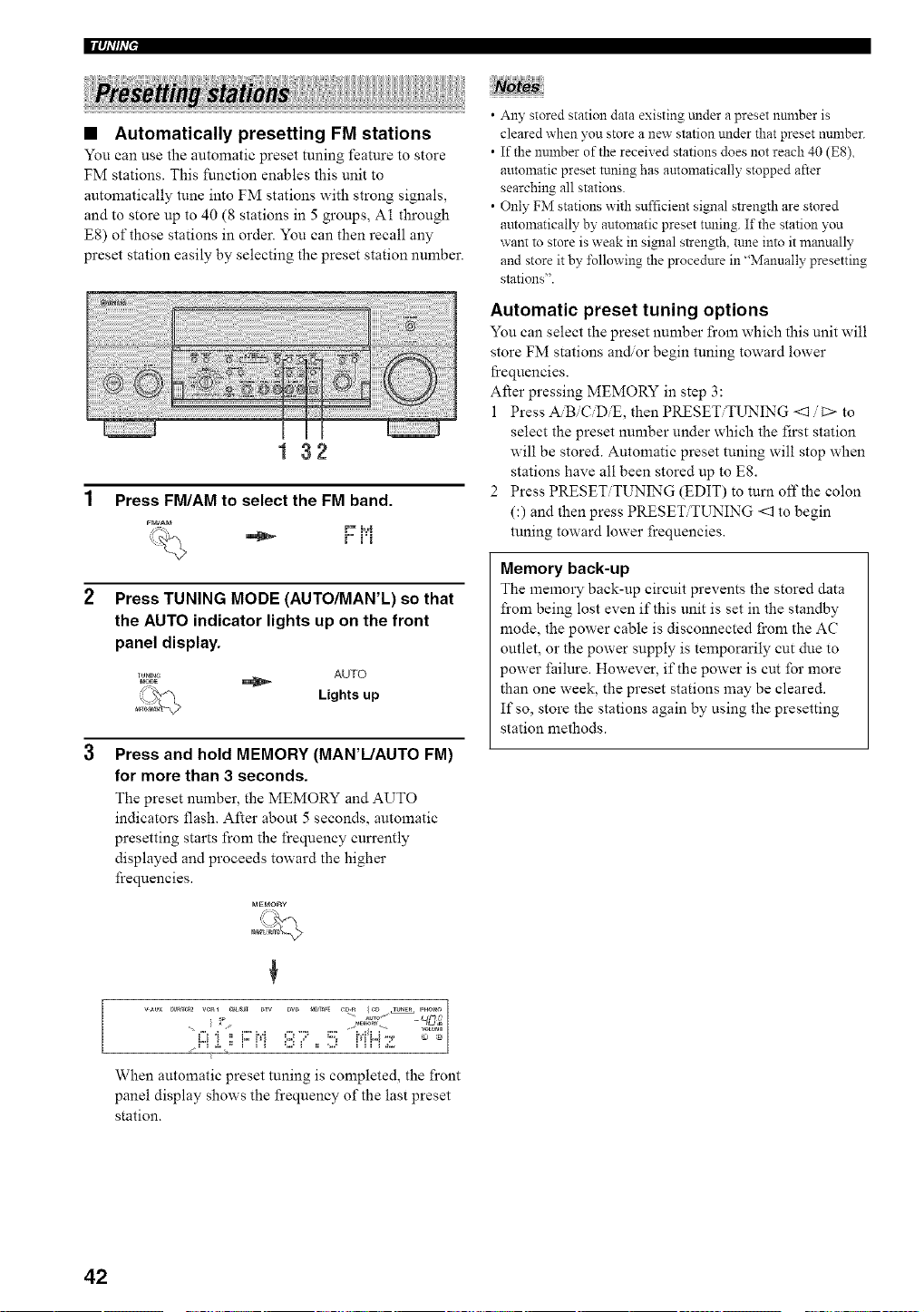
• Automatically presetting FM stations
You can use the automatic preset tuning feature to store
FM stations. This function enables this unit to
automatically tune into FM stations with strong signals,
and to store up to 40 (8 stations in 5 groups, A1 through
E8) of those stations in order. You can then recall any
preset station easily by selecting the preset station number.
132
Press FM/AM to select the FM band.
FM_M t" R','R
r° j'j
Press TUNING MODE (AUTO/MAN'L) so that
the AUTO indicator lights up on the front
panel display.
TU.,.G AUTO
MODE
L_ Lights up
Press and hold MEMORY (MAN'L/AUTO FM)
for more than 3 seconds.
The preset number, the MEMORY and AUTO
indicators flash. After about 5 seconds, automatic
presetting starts from the frequency cun'ently
displayed and proceeds toward the higher
frequencies.
MEr_ORy
WUX 0v_r_a2 Yen1 _t_ Dw Dw _0,_P_ eD-R {CD TU_ER P.O_O
"., , " ,................. , ,_, , VOU_UE
' "i22_ ' . .
When automatic preset tuning is completed, the front
panel display shows the frequency of the last preset
station.
• Any stored station data existing trader a preset number is
cleared when you store a new station under that preset nnmber.
• If the number of the received stations does not reach 40 (E8),
automatic preset tuning has amomatically stopped after
searching all stations.
• Only FM stations with sufficient signal strength are stored
automatically by automatic preset ttming. If the station you
want to store is weak in signal strength, tune into it mammlly
and store it by ±\_llowing the procedure in "Manually presetting
stations".
Automatic preset tuning options
You can select the preset number from which this unit will
store FM stations and/or begin tuning toward lower
l}equencies.
After pressing MEMORY in step 3:
1 Press A'BiC'D_, then PRESET/TUNING <1 / C> to
select the preset number under which the first station
will be stored. Automatic preset tuning will stop when
stations have all been stored up to E8.
2 Press PRESET/TUNING (EDIT) to turn off the colon
(:) and then press PRESET/TUNING <1 to begin
tuning toward lower frequencies.
Memory back-up
The memory back-up circuit prevents the stored data
from being lost even if this unit is set in the standby
mode, the power cable is disconnected from the AC
outlet, or the power supply is temporarily cut due to
power failure. However, if the power is cut for more
than one week, the preset stations may be cleared.
If so, store the stations again by using the presetting
station methods.
42
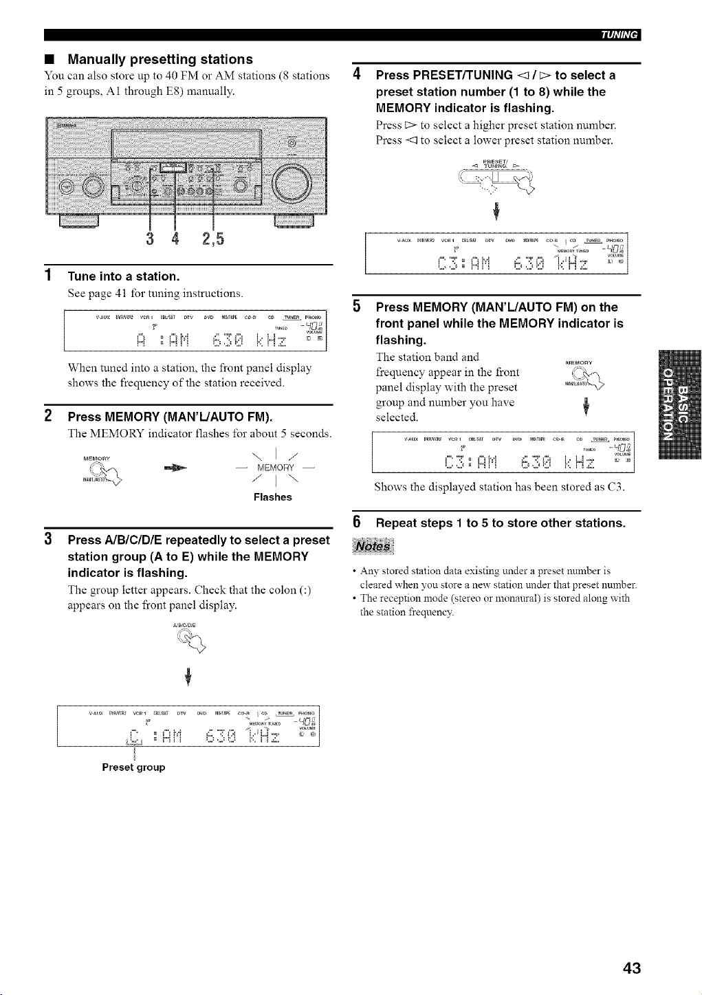
• Manually presetting stations
You can also store up to 40 FM o1"AM stations (8 stations
in 5 groups, A1 through E8) manually.
3 4 2,5
1 Tune into a station.
See page 41 for tuning instructions.
vAux m_D MD,mPECD_ e_ TU_Z_ PHO_
., _P ..... TU.EO --
When tuned into a station, the front panel display
shows the frequency of the station received.
2 Press MEMORY (MAN'L/AUTO FM).
The MEMORY indicator llashes for about 5 seconds.
\1/
MEr_O_W
//_=%
_
+: / I"
Flashes
[
Press AIBICIDIE repeatedly to select a preset
station group (A to E) while the MEMORY
indicator is flashing.
The group letter appem's. Check that the colon (:)
appears on the front panel display.
vAux _vRa/c_ v¢_l _t,S_T DTV
Preset group
lqi'/h'P
Press PRESET/TUNING <1 / c> to select a
preset station number (1 to 8) while the
MEMORY indicator is flashing.
Press C> to select a higher preset station number.
Press <1 to select a lower preset station number.
P_ESET/
,< TUN_Nra t>
+
++ ++°_++ -
t • ": ++ i + '*++ :1++ ": + ++ t.,+LJ +'+, _+ +t
=., ,j =+ t+"+t + =.t ,j =:,.t t++"t + .+:,.
t
Press MEMORY (MAN'L/AUTO FM) on the
front panel while the MEMORY indicator is
flashing.
The station band and
frequency appear in the front _+_++o+o_
panel display with the preset
group and number you have
selected.
vAux DVR_ ve_ _m,S_T DW DVD m_,TAP_CD_ e_ _U_ PHOTO
" : ° '+++++ 6 3 8 t,::H;+:: °++++'|
Shows the displayed station has been stored as C3.
Repeat steps 1 to 5 to store other stations.
• An 3' stored station data existing under a preset nnmber is
cleared when you store a new station under that preset number.
• The reception mode (stereo or monaural) is stored along with
the station frequenc3:
43
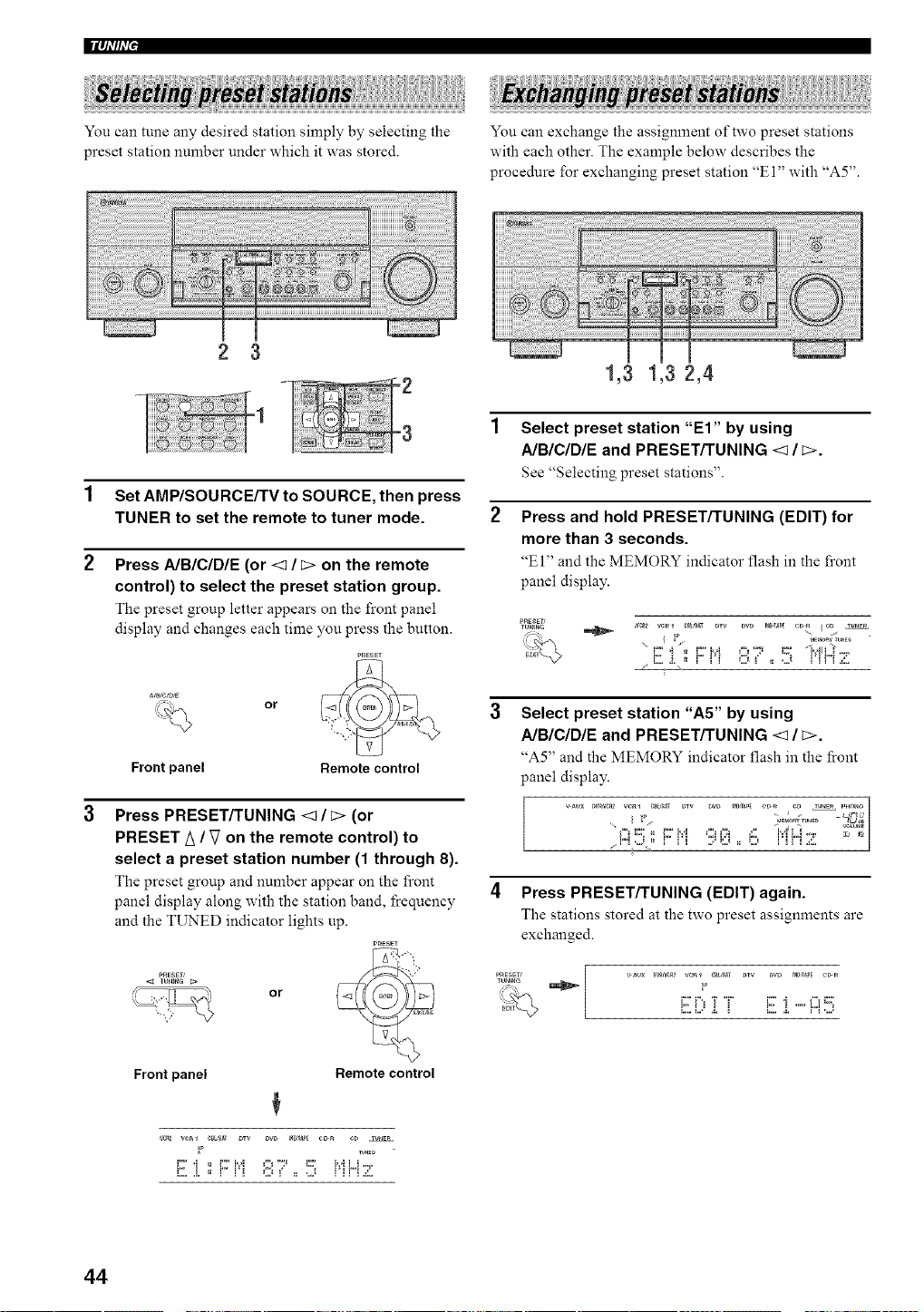
llqi'lh'P
You can tune any desired station simply by selecting the
preset station number under which it was stored.
You can exchange the assignment of two preset stations
with each other. The example below describes the
procedure for exchanging preset station '+El" with "A5".
2 3
1 Set AMP/SOURCE/TVto SOURCE, then press
TUNER to set the remote to tuner mode. 2
2 Press AIBICIDIE (or <1 / [> on the remote
control) to select the preset station group.
The preset group letter appears on the front panel
display and changes each time you press the button.
PnESET
_% or
Front panel Remote control
Press PRESET/TUNING <1/ E> (or
PRESET A / V on the remote control) to
select a preset station number (1 through 8).
The preset group and number appear on the front
panel display along with the station band, frequency
and the TUNED indicator lights up.
PRESET
TUHmG _
i_ :, .-+, , or
Front panel Remote control
+
_2 wnl _BL'_ DTV DVD m_,_ C_R CD TU_CR
L+ • ++ L+ t++'+ =++J +'+ ='+++ t++'+L+t-+++
L.. ,+. =+ t t + =.t + m ,.t t + ] + 2
1,3 1,3 2,4
Select preset station "El" by using
A/B/C/DIE and PRESET/TUNING <1 / c>.
See '+Selecting preset stations".
Press and hold PRESET/TUNING (EDIT) for
more than 3 seconds.
'+El" and the MEMORY indicator flash in the front
panel display.
Select preset station "A5" by using
A/B/C/D/E and PRESET/TUNING <1 / c>.
_+A5" and the MEMORY indicator flash in the front
panel display.
I
+ ..................... +'3 .+,. V+Lmm
+ + _<+,+m i,+ 1'+3 =++,1+ +++ +: + t'+3 L++ +'+' + m
/t"+_+++ t t + +++,+:,._ + ++,.t t +t + .+:,. |
4 Press PRESET/TUNING (EDIT) again.
The stations stored at the two preset assignments are
exchanged.
_p
+:::'+'+'+'"++ E ++-+'++
L... t,F .+. + .+. t+"+ ,.,._
44
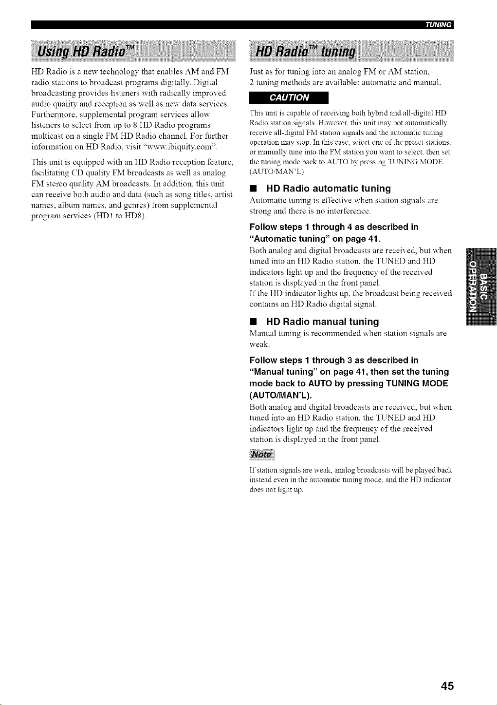
Iql'lfl'iJ
HD Radio is a new technology that enables AM and FM
radio stations to broadcast programs digitally. Digital
broadcasting provides listeners with radically improved
audio quality and reception as well as new data smwices.
Furthermore, supplemental program services allow
listeners to select fi'om up to 8 HD Radio programs
mnlticast on a single FM HD Radio channel. For further
information on HD Radio, visit "www.ibiquity.com".
This unit is equipped with an HD Radio reception feature,
facilitating CD quality FM broadcasts as well as analog
FM stereo quality AM broadcasts. In addition, this unit
can receive both audio and data (such as song titles, artist
names, album names, and genres) from supplemental
program services (HD1 to HD8).
Just as for tuning into an analog FM or AM station,
2 tuning methods are available: automatic and manuah
[_-+fIjt/oJ,R
This trait is capable of receiving both hybrid and all-digital HD
Radio station signals. However. this unit may not automatically
receive all-digital FM station signals and the automatic tuning
operation may stop. In this case, select one of the preset stations.
or manually tune into the FM station you want to select, then set
the tuning mode back to AUTO by pressing TUNING MODE
(AUTOiMAN'L).
• HD Radio automatic tuning
Automatic tuning is effective when station signals are
strong and there is no interference.
Follow steps 1 through 4 as described in
"Automatic tuning" on page 41.
Both analog and digital broadcasts are received, but when
tuned into an HD Radio station, the TUNED and HD
indicators light up and the frequency of the received
station is displayed in the front panel.
If the HD indicator lights up, the broadcast being received
contains an HD Radio digital signal.
• HD Radio manual tuning
Manual tnning is recommended when station signals are
weak.
Follow steps 1 through 3 as described in
"Manual tuning" on page 41, then set the tuning
mode back to AUTO by pressing TUNING MODE
(AUTO/MAN'L).
Both analog and digital broadcasts are received, but when
tuned into an HD Radio station, the TUNED and HD
indicators light up and the frequency of the received
station is displayed in the front panel.
If station signals are weak. analog broadcasts will be played back
instead even in the automatic tuning mode, and the HD indicator
does not light up.
45
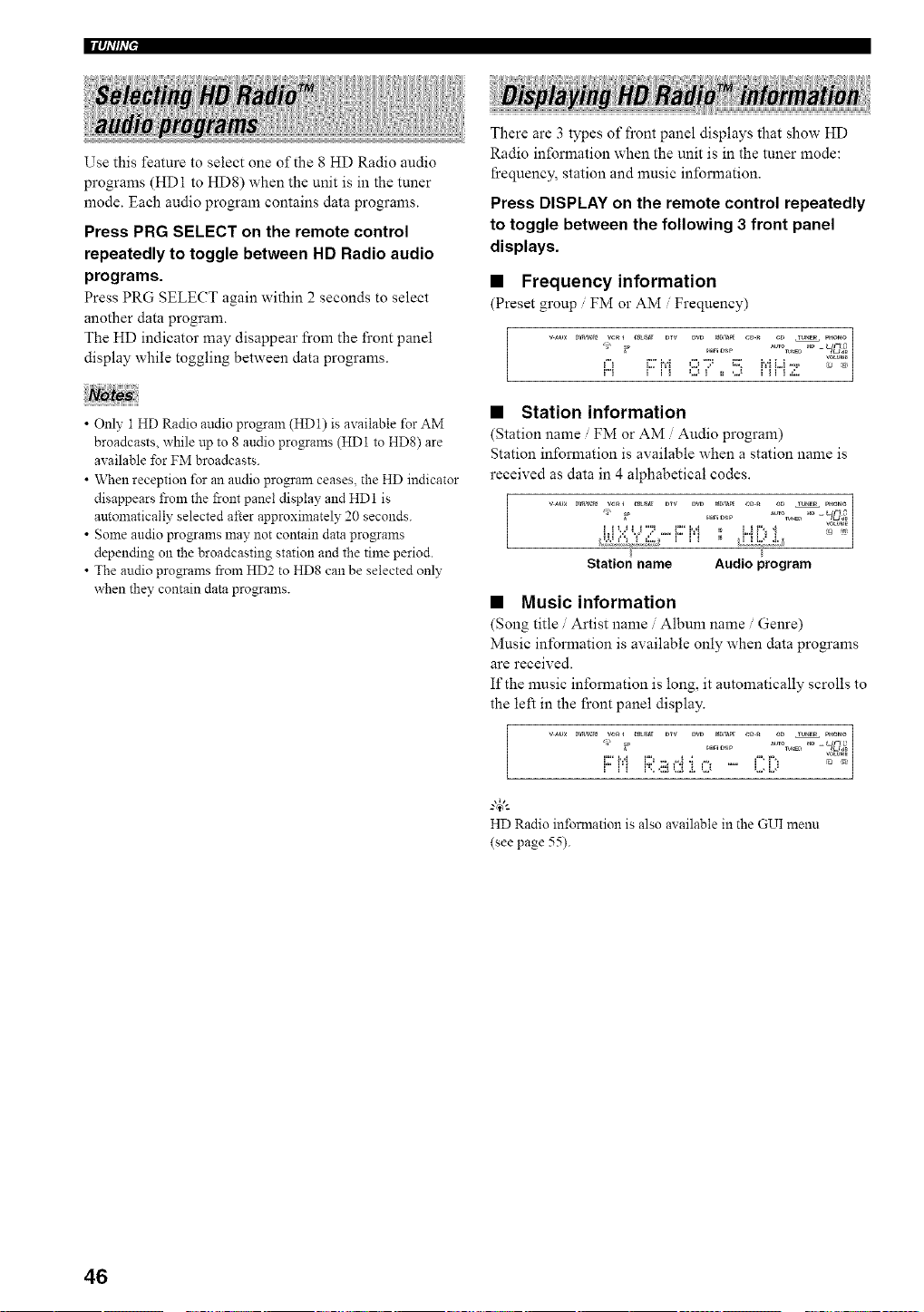
Use this feature to select one of the 8 HD Radio audio
programs (HD1 to HD8) when the unit is in the tuner
mode. Each audio program contains data programs.
Press PRG SELECT on the remote control
repeatedly to toggle between HD Radio audio
programs.
Press PRG SELECT again within 2 seconds to select
another data program.
The HD indicator may disappear lrom the front panel
display while toggling between data programs.
• Only 1 HD Radio audio program (HD1) is available for AM
broadcasts, while up to 8 audio programs (HD1 to HD8) are
available for FM broadcasts.
• When reception for an audio program ceases, the HD indicator
disappears from the front panel display and HD 1 is
automatically selected after approximately 20 seconds.
• Some audio programs may not contain data programs
depending on the broadcasting station and the time period.
• The audio programs from HD2 to HD8 can be selected only
when they contain data programs.
There are 3 types of front panel displays that show HD
Radio information when the unit is in the tuner mode:
ficequency, station and music inlbrmation.
Press DISPLAY on the remote control repeatedly
to toggle between the following 3 front panel
displays.
• Frequency information
(Preset group FM or AM Frequency)
vAu× D_c_ vcR_ _t,_l Dry Dw t_0n_p_ _D_ cD TU_ER P_O_O_
izi i:::H 87o ',5 i"iH:;!: |
• Station information
(Station name FM or AM Audio program)
Station information is available when a station name is
received as data in 4 alphabetical codes.
Station name Audio program
• Music information
(Song title Artist name Album name Genre)
Music information is available only when data programs
are received.
If the music information is long, it automatically scrolls to
the left in the front panel display.
!
HD Radio in±brmation is also available in the GUI menu
(see page 55).
46
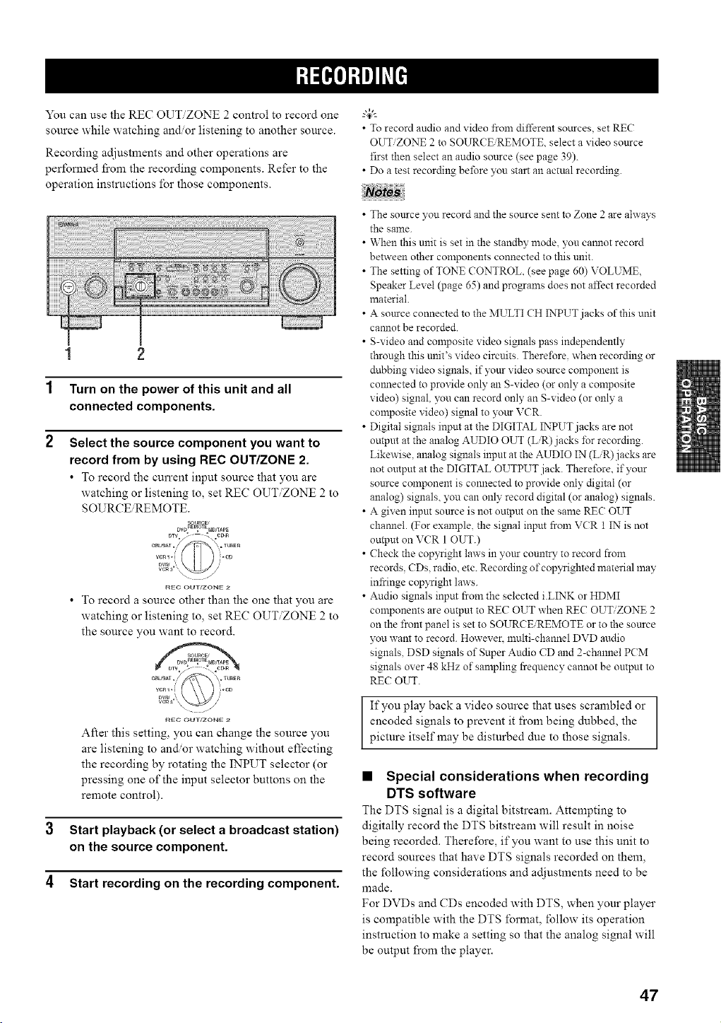
You can use the REC OUT/ZONE 2 control to record one
source while watching and/or listening to another source.
Recording adjustments and other operations are
performed fi'om the recording components. Refer to the
operation instructions for those components.
1 2
1 Turn on the power of this unit and all
connected components.
2
Select the source component you want to
record from by using REC OUT/ZONE 2.
• To record the current input source that you are
watching or listening to, set REC OUT/ZONE 2 to
SOURCE REMOTE.
DVD_SP_OTEpaDrrApE
r_Ec OUTrZONE 2
• To record a source other than the one that you are
watching or listening to, set REC OUT/ZONE 2 to
the source you want to record.
_EC OUT/ZONE 2
After this setting, you can change the source you
are listening to and'or watching without effecting
the recording by rotating the INPUT selector (or
pressing one of the input selector buttons on the
remote control).
3 Start playback (or select a broadcast station)
on the source component.
4 Start recording on the recording component.
• To record audio and video from differeut sources, set RE(;
OUT/ZONE 2 to SOURCE/REMOTE, select a video source
first then select an audio source (see page 39).
• Do a test recording before you start an actual recording.
• The source you record and the source sent to Zone 2 are always
the same.
• When this unit is set in the standby mode, you camlot record
between other components connected to this unit.
• The setting of TONE CONTROL. (see page 60) VOLUME.
Speaker Level (page 65) and programs does not affect recorded
material.
• A source connected to the MULTI CH INPUT jacks of this unit
camlot be recorded.
• S-video and composite video signals pass independently
through this unit's video circuits. Therel\_re. when recording or
dubbing video signals, if your video source component is
colmected to provide only an S-video (or only a composite
video) signal, you can record only an S-video (or only a
composite video) signal to your VCR.
• Digital signals input at the DIGITAL INPUT jacks are not
outpm at the analog AUDIO OUT (L/R) jacks for recording.
Likewise, analog signals input at the AUDIO IN (L/R)jacks are
not omput at the DIGITAL OUTPUT jack. Therefore. if your
source colnponent is connected to provide only digital (or
analog) signals, you can only record digital (or analog) signals.
• A given inpm source is not output on the same REC OUT
chamlel. (For example, the signal input from VCR 1 IN is not
output on VCR 1 OUT.)
• Check the cop?Tight laws in yurLr country to record from
records. CDs, radio, etc. Recording of copyrighted material may
infringe cop?Tight laws.
• Audio signals input from the selected i.LINK or HDMI
components are output to REC OUT when REC OUT/ZONE 2
on the front panel is set to SOURC_REMOTE or to the source
you want to record. However. mulfi-channel DVD audio
signals, DSD signals of Super Audio CD and 2-channel PCM
signals over 48 kHz of sampling frequency cannot be output to
RE{2?OUT.
If you play back a video source that uses scrambled or
encoded signals to prevent it from being dubbed, the
picture itself may be disturbed due to those signals.
• Special considerations when recording
DTS software
The DTS signal is a digital bitstream. Attempting to
digitally record the DTS bitstream will result in noise
being recorded. Therefore, if you want to use this unit to
record sources that have DTS signals recorded on them,
the following considerations and adjustments need to be
made.
For DVDs and CDs encoded with DTS, when your player
is compatible with the DTS format, tbllow its operation
instruction to make a setting so that the analog signal will
be output from the player.
47
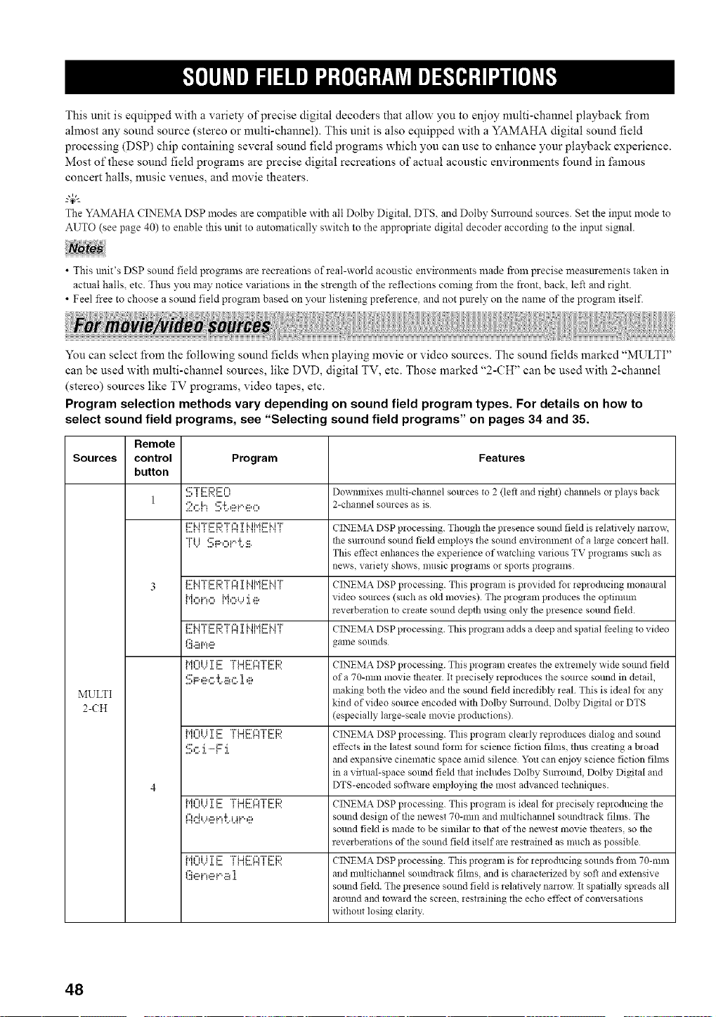
This unit is equipped with a variety of precise digital decoders that allow you to enjoy nmlti-channel playback from
ahnost any sound source (stereo or multi-channel). This unit is also equipped with a YAMAHA digital sound field
processing (DSP) chip containing several sound field programs which you can use to enhance your playback experience.
Most of these sound field programs are precise digital recreations of actual acoustic environments found in fi_mous
concert halls, nmsic venues, and movie theaters.
The YAMAHA CINEMA DSP modes are compatible with all Dolby Digital. DTS. and Dolby Surround sources. Set the input mode to
AUTO (see page 40) to enable this unit to automatically switch to the appropriate digital decoder according to the input signal.
• This unit's DSP sound field programs are recreations of real-world acoustic em ironments made from precise measurements taken in
actual halls, etc. Thus you may notice x ariations in the strength of the reflections coming from the front, back, left and right.
• Feel free to choose a somld field program based on ?'our listening preference, and not purely on the name of the program itself.
You can select from the following sound fields when playing movie or video sources. The sound fields marked "MULTI"
can be used with nmlti-channel sources, like DVD, digital TV, etc. Those marked "2-CH" can be used with 2-channel
(stereo) sources like TV programs, video tapes, etc.
Program selection methods vary depending on sound field program types. For details on how to
select sound field programs, see "Selecting sound field programs" on pages 34 and 35.
Remote
Sources control Program Features
button
....*:::'"i"i:::'i:::,ii::'¢"l,i l...l...i....n..3 Downulixes nltllti-channeI somces to 2 (left and fight) challnels Ol plays back
1
2._:::.i'3'::::'['.,::ai"'_::,,"_ 2-chain]el sources as is
i....i 'ii::' M "i" i::' [:, "F,"_=i...._'.. _ m a.i'HTM i'd _::'M "Fli....i 'i _ C 12",TEMA DSP processing. Though tile presence SOlllld field is ielafivelv_ na no w,
"i"i i ,::::i:::.,-._P'l'. 4::. the surround somld field employs the sound environment of a large concmt hall.
i ",,,' ,.............
This effect enhances the experience of watching various TV programs such as
news. variety shows, music programs or sports programs
i:::'M "F i::' iD "F l"_ T M i',_i2' M "F
3 _...._'__ _...._'.._ _".,a._'_ _..._'__ CINEMA DSP processing. This program is provided fol ieproducing monamal
i"h",i."u", N,"_u i ,::a video sources (such as old movies). The program produces the optimum
revmberation to create smmd depth using only the presence sound field.
_....=._i:::'M "i"i:::'_::,"r,"__...._'.._ _".,._._'_TMi',__::'M"r....._'__ CINEMA DSP processing. This program adds a deep and spatial feeling to video
(!!b_ii!r,=!e game sounds
I I',,,'".",l,l,,,,i"il"di T_::' "FL.ii::'¢"¢T'i:::'i::'l1II,,,,I"]I I,,,,I". CINEMA DSP processing. This program creates file extiemely wide SOtllld field
q _::.,::w".']'..::_,"."l _:::, of a 70-rain movie theateL It p_ecisely reproduces the source solmd in detail,
MULTI making both the video and the sound field inmedibly _eal This is ideal tbz an?,
kind of video source encoded with Dolby Surround, Dolby Digital or DTS
2-CH (especially large-scale movie productions)
il,...,.v..i.l....i"i+"di Tg:' "FL.ii::'¢"F'i"g:'i::,_1ll....r".'I l....l'.. CINEMA DSP p!ocessing. This program clearly reproduces dialog and sound
S,:::.:i.'1:::' :i. effects in the latest sound form tb* science fiction fihns, thus creating a b*oad
and expansive cinematic space amid silence "_m can enjoy science fiction films
in a virtual-space solmd field that includes Dolby Surround, Dolby Digital and
4 DTS-encoded sofiwa, e employing the most advanced techniques.
__u...=.._._....i"i_"'ii T_::' "ri...ii:::',"_"r'_::'i:::,__.....m __...._... CINEMA DSP processing. This program is ideal for precisely reproducing t!le
l:::h"iLh:::,i.",'i'.i_"._:::, som]d design of the newest 70-man and multichannel soundtrack fihns. The
sound field is made to be similar to that of the newest movie theaters, so the
revmberations of t!le sound field itself are rest*ained as much as possible
__u......_._....i"i_"'ii Ti:::' "i%.ii:::',"_'T'i:::'i:::,__H....r".,__...._'.. CINEMA DSP processing. This program is for ieproducing SOllnds fiom 70-mm
l'::i_:::,i.%::,i."..::a'i and multichannel soundtrack fihns, and is cha*acterized by soft and extensive
solmd field. The presence sound field is relatively na**ow It spatially spreads all
a*olmd and toward the screen. *estraining the echo effect of conve*sations
without losing cla*ity
48
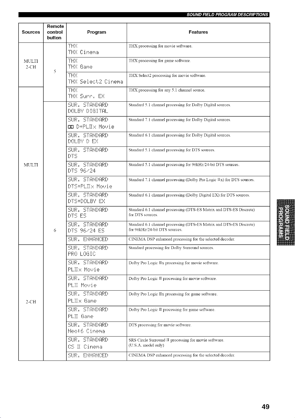
"_e]ll_Vel_l:lllel:d:£eI_:y_qi_lel_._etMI21[e]_vg
Remote
Sources control Program Features
button
THX processing fol movie soflwale.
MULTI THX processing fol game sol, rare
2-CH
5
THX Select2 processing t)l movie software.
MULTI
2-CH
FH::::13.ii.:.,r,,e
"H...i_...:
L=',,._I,,,,_,,' _ I,,,' ,l, ',,,I ,l, I I"41....
no i)+F'L.)2iI:=<M,:::,_...,:i.e
....I,,,J1',, :: ,,,J I r"ll _L,,,r,,ll,, i,,=,
RqTi i:::',_') i":_ K=.:'::.
....I,,,.4',, :: ,,,J I r"ll _L,,,r,,ll,, i,,
i%7"_:::'
....i,,,.4',, :: ,,,.I I r"ll _L,,,r,,ll,, i,,,
...._,..._i'.. := ...J i r"u _L..'r"u'=J.d
t...*_....,, t t..'rT*:'::r"h"0.J'};::,
.... ii,,.ll,, , :: ,,,.i i i'71 _L,,,I,,,II,. L,
I'_ t _,,, ,,,,l,:. ,,-,,,,'l I,,, ,,.
,:::JH:::, J::r_..JUr,_..Jr.J::rJ',,
.... li,,._l,, , 1: ,,,._ i _,,,ii _L,,,r,,II%L...
i::M:::."_ i ¢"H':::T ¢"
....,,.Jv.. :: ...._ t r"u _L..'r"u'.J...*
i::)i TT* . r_]l"tLJ 'I i:::,
...... L:..
,:::"iii:::, ,::77"i"i i..i r'., i"i i::M%
i:::i....:i:[i"i,:::,,...,:i.,ii_
,:::7 ii:::, ,:::'i" 1'7 M r ',, _'7i:::d".,
....,,,Jv,, :: ,,,., i r"u _L,,'r"u'.J,.."
,:::7 ii:::, ,:::'r' 1'7 M r',, 1'7i:::d%
i::,i i7" ]':'_,::M','H::,_
i L..L_.
....,,,,.4,,, :: ,,,., i r"u _L,,'r"u'=J,,=*
I"_::_"_ ',',I:'*, I...: I i'Te.r"!.ii_
,::.'7 ii:::, ,::."7" 1'7 M r',, 1'7i:::, r'.,
I :'% _i I :I i,Ti::,_r4J::i
,:::7 ii:::, i:::"i,, ii,,,i ¢7 M _"' i:::T',
THX processing for any 5.1 channel source.
Standard 5 1 channel processing t)l Dolby Digital sources
Standard 7 t channel processing t)l Dolby Digital sources
Standard 6 t channel processing t)l Dolby Digital sources
Standard 5.1 channel processing t)l DTS sources
Standard 5.1 channel processing t)l 96kHzi24-bit DTS sources.
Standard 7.1 channel processing (Dolby Pro Logic II x) for DTS sources
Standard 6.1 channel processing (Dolby Digital EX) for DTS sources
Standard 6.1 channel processing (DTS-ES Matrix and DTS-ES Discrete)
for DTS sources
Standard 6.1 channel processing (DTS-ES Matrix and DTS-ES Discrete)
for 96kHzi24-bit DTS sources.
CINEMA DSP enhanced processing for the selected decoder
Standard processing for Dolby Sunolmd sources
Dolby Pro Logic Iix processing for movie software
Dolby Pro Logic 1I processing for movie software
Dolby Pro Logic I/x processing for game software.
Dolby Pro Logic l! processing for game software.
DTS processing for movie software
SRS Circle Smround i1 processing for movie software
(USA. model only)
CINEMA DSP enhanced processing tbr the selected decoder
49
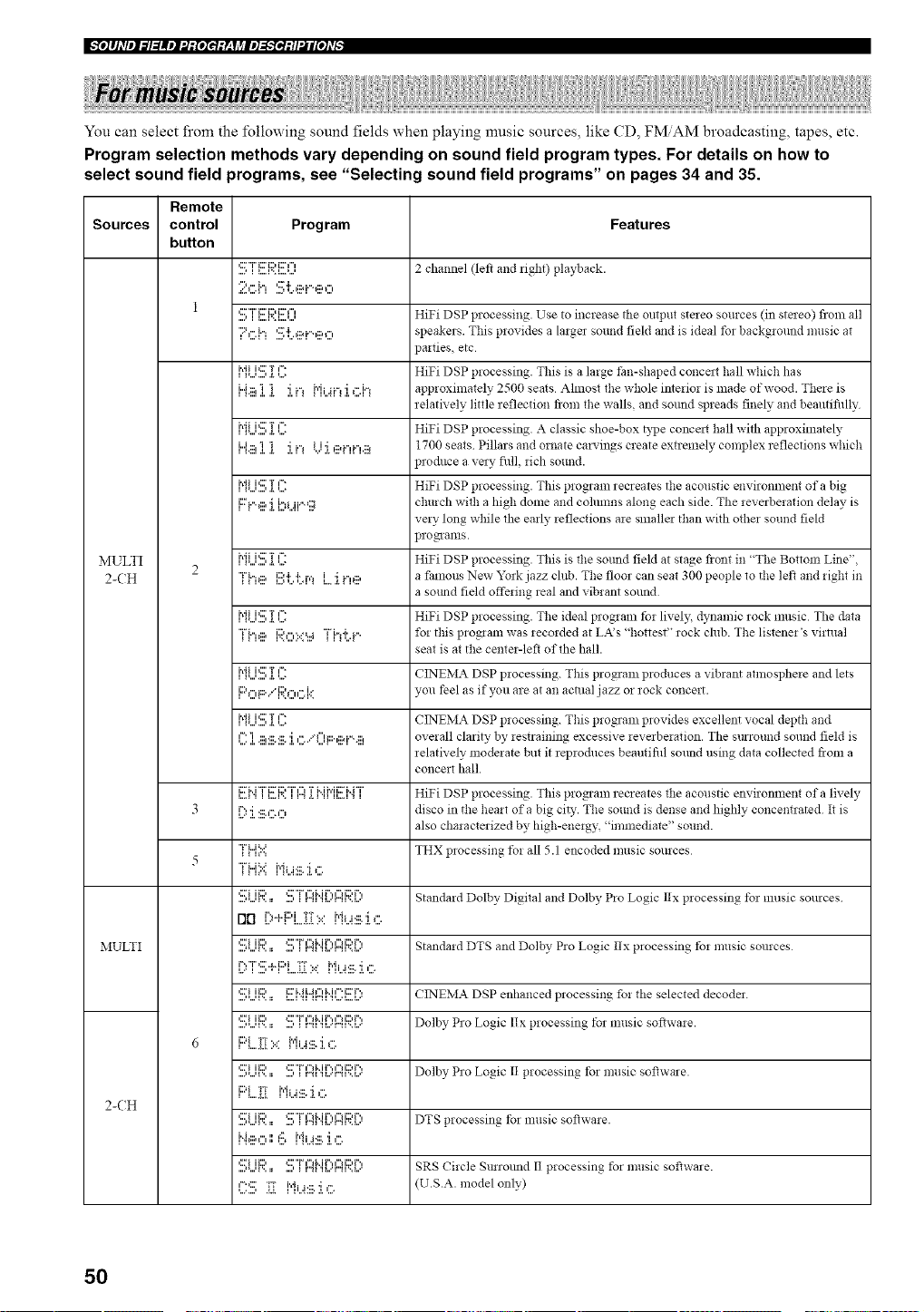
_fe]lJ_Vellll_llel'.l:[eItq:V__yj_le]_fel:/l'_li[e]_v_
You can select fi'om the following sound fields when playing music sources, like CD, FMAM broadcasting, tapes, etc.
Program selection methods vary depending on sound field program types. For details on how to
select sound field programs, see "Selecting sound field programs" on pages 34 and 35.
Sources
MULTI
2-CH
MULTI
2-(H
Remote
control
button
Program
2c1_ St.ei..eo
...., i I....V=A..rA..'
7,:::.1_St.ei..eo
i',ii i':::iT F:
I..a.:::lI I "i i."_l','li_i."_'i _".I."_
i',ii ic; T I":
i'dii':::;T F:
i'diP:::;T F:
"[i"ie i::::'i'.'i'.J',*,i'i i.",_::,
i'dii':::;TF:
i]_e i.:',...,.=.:.=..4Tht.{....
i'dii':::;TF:
I°'ll''ii:::'..'*I'::'l''ii'*I.;"
i',ii i_::;T I":
I : I .:::l.:::..:::.'i i'....q li:::.gai.-**:::l
i2FM "T' i2F1:2,"r' ¢"1 T M h.ii::FH T
I..?:I.::::.,:::.O
_i h":
iiii::i i"i_...i:::_.:i.,:::.
,2Fi lid (:F"i%U'_Mi",iu'li:2,r ',
DD [:,+i::'i....??b.=:i'%i:_ii.:b:::.
,::ri iiD *::F"i%"1M r'., ¢"H:2,r'.,
.... l_...ll'.. =: ...i i i=41 .ll....l=']i,= i..
qi ii:;)., i:::'i'._i41:::li'..il=:i::ri":,
,2[*i lid (:F"i"tU'_Mr",tu'iiDr ',
,::;*i lid =::F"i%"l M i", ¢"1i::)r '.,
....,=...q'.. :: ..., _ i=41 'll...'r'41',.l..
,::_i lid =::F"i" ¢"1M i", ¢"1i::)r'.,
Ng:,:"l ',',I:", rqi J_::.'i ¢".
,2[*i lid (:F"i%U'_Mr",tu'iiDr ',
....,=...q'.. :_ ..., _ i"41 'll...'r'41',.l..
(]::!!!; :[{ i"iJ..4:iii.:i.,::*
Features
2 channel (left and right) playback.
HiFi DSP processing. Use to increase the output stezeo sources (in stmeo) from all
speakers. This provides a largm sound field and is ideal tbr background music at
)arties, etc
HiFi DSP processing. This is a large fan-shaped concmt hall which has
approximately 2500 seats Almost the whole interior is made of wood. There is
relatively little reflection fiom the walls, and sound spreads finely and beantifidly
HiFi DSP processing. A classic shoe-box D,pe concmt hall with approximately
1700 seats Pillars and ornate carvings create extremely complex reflections which
)roduce ave W fidl, rich sound.
HiFi DSP processing. This program recreates the acoustic environment of a big
church with a high dome and cohunns along each side. The reverberation delay is
very long while the early reflections are smallm than with othm sound field
pro mams.
HiFi DSP processing. This is the som_d field at stage fiont in "The Bottom Line",
a famous New York jazz club. The floor can seat 300 people to the left and right in
a smmd field offering real and vibrant sollnd
HiFi DSP processing. The ideal program tbr lively, dynamic rock music The data
for this proNam was recorded at LA's "hottest" rock club. The listener's virtual
seat is at the center-lef_ of the hall.
CTNEMA DSP processing. This program produces a vibrant atmosphere and lets
you feel as if you are at an actual jazz or rock concert.
CTNEMA DSP processing. This program provides excellent vocal depth and
overall clarity by restraining excessive reverberation. The s:nround sound field is
relatively moderate but it reproduces beautifid sollnd using data collected flora a
concert hall.
HiFi DSP processing. This program recreates the acoustic environment of a lively
disco in the heart of a big ciD,. The sound is dense and highly concentrated It is
also characterized by high-energy, "immediate" sound.
THX processing t_r all 5.1 encoded music sources
Standard Dolby Digital and Dolby Pro Logic lIx processing tbr music sources
Standa:d DTS and Dolby Pro Logic llx processing to: music sources
CTNEMA DSP enhanced processing fo:the selected decoder.
Dolby Pro Logic Ilx processing tbr music sofiwa:e.
Dolby Pro Logic II processing tbr music software.
DTS processing for music sof_wa:e.
SRS Circle Smrotmd I! processing for music software.
U.S.A. model only)
50
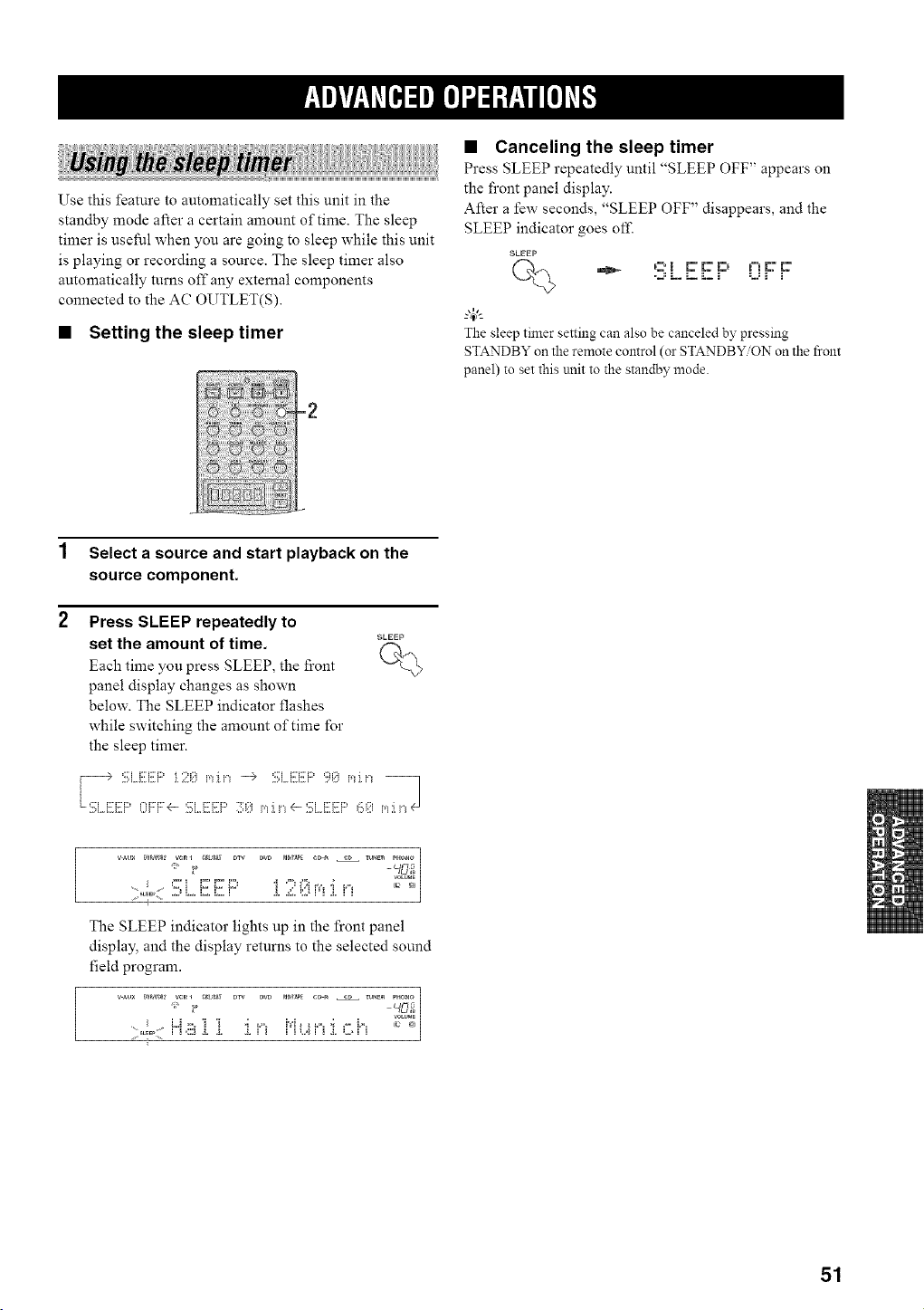
Use this feature to automatically set this unit in the
standby mode after a certain amount of time. The sleep
timer is useful when you are going to sleep while this unit
is playing or recording a source. The sleep timer also
automatically turns off any external components
connected to the AC OUTLET(S).
• Setting the sleep timer
1 Select a source and start playback on the
source component.
2 Press SLEEP repeatedly to
SLEEP
set the amount of time. (_
Each time you press SLEEP, the front
panel display changes as shown
below. The SLEEP indicator flashes
while switching the amount of time for
the sleep timer.
'::J F:F:F:' :';: i,'_Ji'_ --) '::J F:F:F:'':_:: i,'_i'_
• Canceling the sleep timer
Press SLEEP repeatedly until "SLEEP OFF" appears on
the front panel display.
After a few seconds, "SLEEP OFF" disappears, and the
SLEEP indicator goes off.
SLEEP
(_ .._ ,::! _ Er!:, ,¢!c:Er
=_= i== i== _ i ====i 1
"4(:
The sleep timer setting can also be canceled by pressing
STANDBY on the remote control (or STANDBY/ON on the front
panel) to set this unit to the standby mode.
i I
The SLEEP indicator lights up in the front panel
display, and the display returns to the selected sound
field program.
J
:::,0:, H,!ii_]. ]. :i.n J"iu n :i.,:;h .... j
51
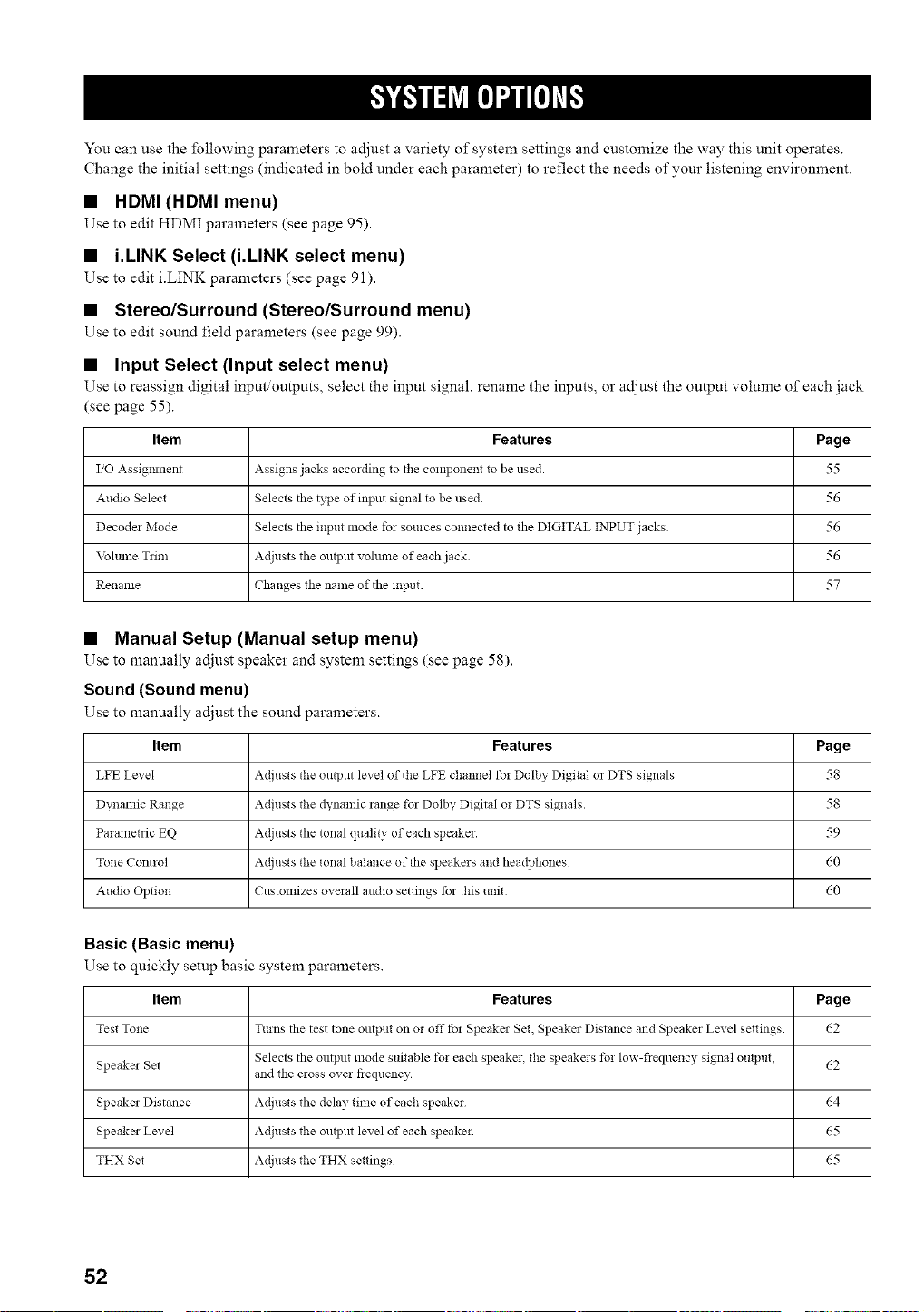
You can use the following parameters to adjust a variety of system settings and customize the way this unit operates.
Change the initial settings (indicated in bold under each parameter) to reflect the needs of your listening environment.
• HDMI (HDMI menu)
Use to edit HDMI parameters (see page 95).
• i.LINK Select (i.LINK select menu)
Use to edit iiINK parameters (see page 91).
• Stereo/Surround (Stereo/Surround menu)
Use to edit sound field parameters (see page 99).
• Input Select (Input select menu)
Use to reassign digital input outputs, select the input signal, rename the inputs, or adjust the output volume of each jack
(see page 55).
Item
I/O Assigillnent
Audio Select
Decodel Mode
\blume Tlim
Rename
Features Page
Assigns jacks accolding to the component to be used. 55
Selects the t_]Je of input signal to be used 56
Selects the input mode tbr sources connected to the DIGITAL INPUT jacks 56
Adjusts the output vohune of each jack 56
Changes the name of the input. 57
• Manual Setup (Manual setup menu)
Use to manually adjust speaker and system settings (see page 58).
Sound (Sound menu)
Use to manually adjust the sound parameters.
Item Features Page
LFE Level Adjusts the output level of the LFE channel t_r Dolby Digital ol DTS signals 58
Dynamic Range Adjusts the dynamic range for Dolby Digital or DTS signals. 58
Parametric EQ Adjusts the tonal quality of each speaker. 59
Tone Control Adjusts the tonal balance of the speakers and headphones 60
Audio Option Customizes overall mldio settings tbr this unit 60
Basic (Basic menu)
Use to quickly setup basic system parameters.
Item Features Page
Test Tone Turns tile test tone output on o! off fol Speakel Set, Speaker Distance and Speaker Level settings. 62
Selects the output *node suitable t_r each speaker, the speakers t_r low-frequency signal output, 62
Speaker Set and the cross over fiequency
Speakel Distance Adjusts the delay time of each speaker 64
Speaker Level Adjusts the output level of each speaker. 65
THX Set Adjusts the THX settings 65
52
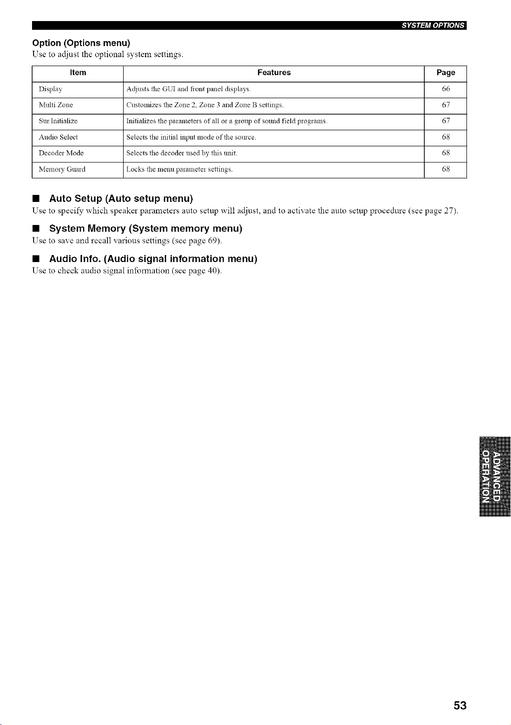
Option (Options menu)
Use to adjust the optional system settings.
Item Features Page
Display Adjusts the GUI and front panel displays 66
Multi Zone Customizes the Zone 2, Zone 3 and Zone B settings 67
Sur Initialize Initializes the parametezs of all or a group of sound field programs. 67
Audio Select Selects the initial input mode of the source. 68
Decoder Mode Selects the decoder used by this unit. 68
Memo!), Guard Locks the menu parameter settings 68
• Auto Setup (Auto setup menu)
Use to specify which speaker parameters auto setup will adjust, and to activate the auto setup procedure (see page 27).
• System Memory (System memory menu)
Use to save and recall various settings (see page 69).
• Audio Info. (Audio signal information menu)
Use to check audio signal inlbrmation (see page 40).
53
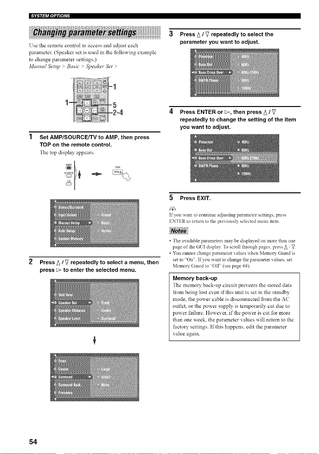
Use the remote control to access and adjust each
parmneter. (Speaker set is used in the lbllowing example
to change parameter settings.)
2viamml Setllp > Basic > 5_eaker Set >
Press A / V repeatedly to select the
parameter you want to adjust.
Set AMP/SOURCE/TV to AMP, then press
TOP on the remote control.
The top display appears.
4 Press ENTER or c>, then press A / V
repeatedly to change the setting of the item
you want to adjust.
5 Press EXIT.
If you want to continue actiusting parameter settings, press
ENTER to return to the previously selected menu item.
Press A / V repeatedly to select a menu, then
press c> to enter the selected menu.
• The available parameters may be displayed on more than one
page of the GUI display. To scroll through pages, press _ / :7.
• You ca:mot change parameter values when Memo D" Guard is
set to "On". If you want to change the parameter values, set
Memory Guard to "Off' (see page 68).
Memory back-up
The memory back-up circuit prevents the stored data
from being lost even if this unit is set in the standby
mode, the power cable is disconnected from the AC
outlet, or the power supply is temporarily cut due to
power failure. However, if the power is cut for more
than one week, the parameter values will return to the
factory settings. If this happens, edit the parameter
value again.
54
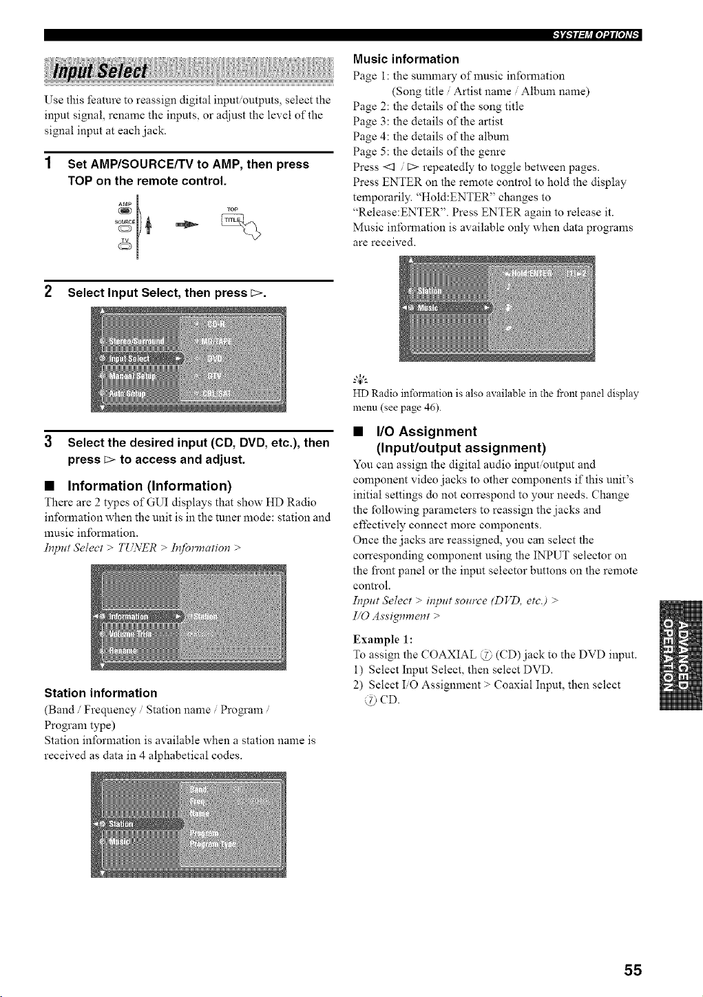
ii ! /I tilillil!lililt
Use this feature to reassign digital input/outputs, select the
input signal, rename the inputs, or adjust the level of the
signal input at each jack.
Set AMP/SOURCE/TV to AMP, then press
TOP on the remote control.
Music information
Page i: the summary of music information
(Song title / Artist name / Album name)
Page 2: the details of the song title
Page 3: the details of the artist
Page 4: the details of the album
Page 5: the details of the genre
Press <1 / C> repeatedly to toggle between pages.
Press ENTER on the remote control to hold the display
temporarily. "Hold:ENTER" changes to
"Release:ENTER". Press ENTER again to release it.
Music information is available only when data programs
are received.
2 Select Input Select, then press E>.
3 Select the desired input (CD, DVD, etc.), then
press _> to access and adjust.
• Information (Information)
There are 2 types of GUI displays that show HD Radio
information when the unit is in the tuner mode: station and
music information.
Input Select > T[LVER > Information >
Station information
(Band / Frequency / Station name / Program /
Program type)
Station information is available when a station name is
received as data in 4 alphabetical codes.
HD Radio information is also available in the t-ont panel display
menu (see page 46).
• I/O Assignment
(Input/output assignment)
You can assign the digital audio input output and
component video jacks to other components if this unit's
initial settings do not correspond to your needs. Change
the following parameters to reassign the jacks and
effectively connect more components.
Once the jacks are reassigned, you can select the
corresponding component using the INPUT selector on
the front panel or the mput selector buttons on the remote
control.
It?put Select > #?put source (DVD, etc.) >
I/0 Assignment >
Example 1:
To assign the COAXIAL @ (CD) jack to the DVD input.
i) Select Input Select, then select DVD.
2) Select IiO Assignment > Coaxial Input, then select
@ CD.
55
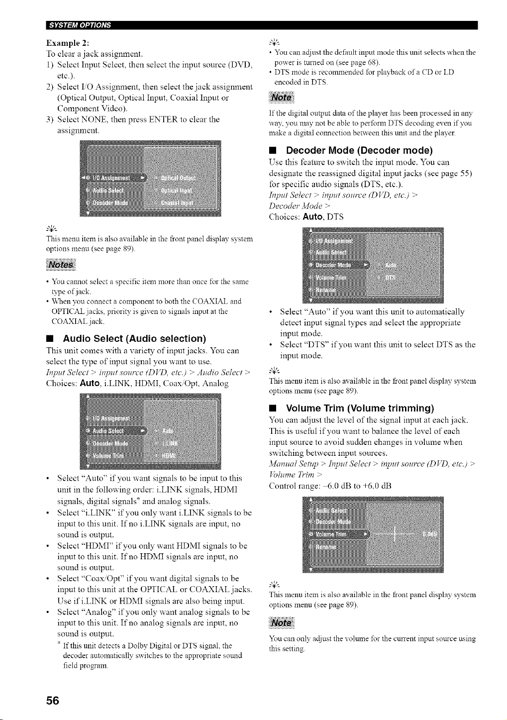
IFJ'i-71_j'_io1_lph'_
Example 2:
To clear a jack assignment.
i) Select Input Select, then select the input source (DVD,
etc.).
2) Select IiO Assignment, then select the jack assignment
(Optical Output, Optical Input, Coaxial Input or
Component Video).
3) Select NONE, then press ENTER to clear the
assignment.
This menn item is also available in the front panel display system
options menn (see page 89).
• You can ac[iust the default input mode this unit selects when the
power is turned on (see page 68).
• DTS mode is recommended for playback ofa (D or LD
encoded in DTS.
If the digital output data of the player has been processed in an?"
wa3\ you may not be able to perform DTS decoding even if you
make a digital cmmection between this unit and the player.
• Decoder Mode (Decoder mode)
Use this feature to switch the input mode. You can
designate the reassigned digital input jacks (see page 55)
for specific audio signals (DTS, etc.).
Input Select > input soz,'ce (D VD, etc.) >
Decoder" 3/lode >
Choices: Auto, DTS
• You cmmot select a specific item more than once lbr the same
type of jack.
• When you connect a component to both the COAXIAL and
OPTICAL jacks, priority is given to signals input at the
COAXIAL jack.
• Audio Select (Audio selection)
This unit comes with a variety of input jacks. You can
select the type of input signal you want to use.
Input Select > input source (DVD, etc.) > Audio 5"elect >
Choices: Auto, iiINK, HDMI, Coax/Opt, Analog
• Select "Auto" if you want signals to be input to this
unit in the Ibllowing order: i.LINK signals, HDMI
signals, digital signals* and analog signals.
• Select "i.LINK" if you only want i.LINK signals to be
input to this unit. If no iiINK signals are input, no
sound is output.
• Select "HDMI" if you only want HDMI signals to be
input to this unit. If no HDMI signals are input, no
sound is output.
• Select "Coax/Opt" if you want digital signals to be
input to this unit at the OPTICAL or COAXIAL jacks.
Use if i.LINK or HDMI signals are also being input.
• Select "Analog" if you only want analog signals to be
input to this unit. If no analog signals are input, no
sound is output.
* If this unit detects a Dolby Digital or DTS signal, the
decoder automatically switches to the appropriate sotmd
field progam.
• Select "Auto" if you want this unit to automatically
detect input signal types and select the appropriate
input mode.
• Select "DTS" if you want this unit to select DTS as the
input mode.
-"4:'-
Thismenu item is also available in the front panel display system
options menu (see page 89).
• Volume Trim (Volume trimming)
You can adjust the level of the signal input at each jack.
This is useful if you want to balance the level of each
input source to avoid sudden changes in volume when
switching between input sources.
34anual Setup > Input Select > input source (D VD, etc.) >
tblume T1"im >
Control range: 6.0 dB to +6.0 dB
This menu item is also available in the front panel display system
options menu (see page 89).
You can only acljust the volulne for the current input source using
this setting.
56
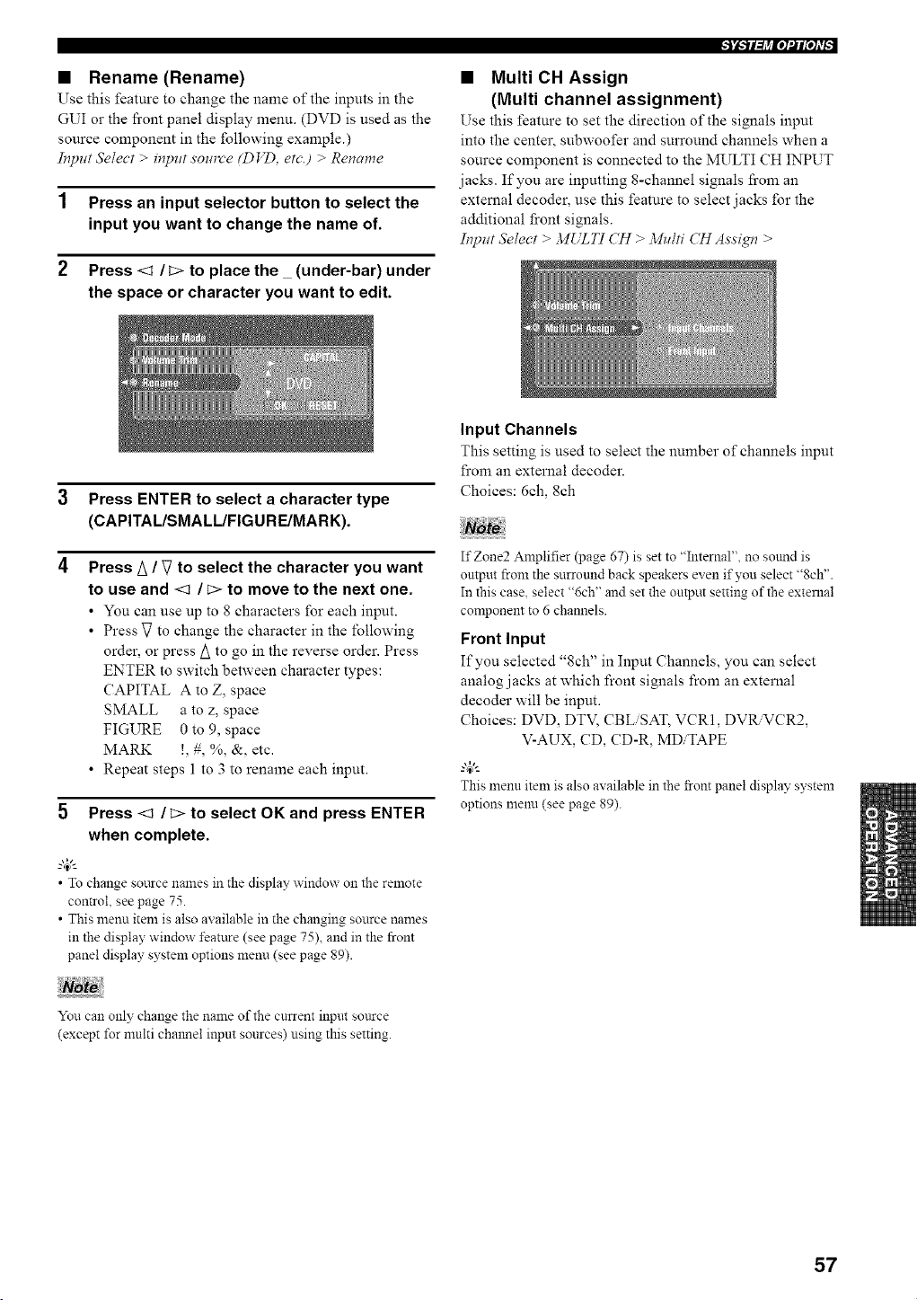
• Rename (Rename)
Use this feature to change the name of the inputs in the
GUI or the fi'ont panel display menu. (DVD is used as the
source component in the following example.)
Input Select > input sou_ve (DVD, etc.) > Rename
1 Press an input selector button to select the
input you want to change the name of.
2 Press <1 /_> to placethe (under-bar) under
the space or character you want to edit.
• Multi CH Assign
(Multi channel assignment)
Use this feature to set the direction of the signals input
into the center, subwoofer and surround channels when a
source component is connected to the MULTI CH INPUT
jacks. If you are inputting 8-channel signals fi'om an
external decoder, use this feature to select jacks for the
additional front signals.
Input Select > MULTI CH > MH/ti CH Assign >
3 Press ENTER to select a character type
(CAPITAL/SMALL/FIGURE/MARK).
4 Press A / V to select the character you want
to use and <1 / E> to move to the next one.
• You can use up to 8 characters for each input.
• Press V to change the character in the following
order, or press A to go in the reverse order. Press
ENTER to switch between character types:
CAPITAL A to Z, space
SMALL a to z, space
FIGURE 0 to 9, space
MARK !, #, %, &, etc.
• Repeat steps 1 to 3 to rename each input.
5 Press <1 / _> to select OK and press ENTER
when complete.
_.,#._
• To change sottrce names in the display window on the remote
control, see page 75.
• This menu item is also available in the changing source names
in the display window feature (see page 75), and in the front
panel display system options menu (see page 89).
Input Channels
This setting is used to select the number of channels input
from an external decoder.
Choices: 6ch, 8ch
If Zone2 Amplifier (page 67) is set to "Internal", no sotmd is
output from the surround back speakers even if you select "8ch".
In this case, select "6ch" and set the output setting of the external
component to 6 channels.
Front Input
If you selected "8ch" in Input Channels, you can select
analog jacks at which front signals from an external
decoder will be input.
Choices: DVD, DTV, CBLiSAT, VCR1, DVtLVCR2,
V-AUX, CD, CD-R, MDiTAPE
This menu item is also available in the front panel display system
options menu (see page 89).
You can only change the name of the current input source
(except for nmlti chmmel inpm sources) using this setting.
57
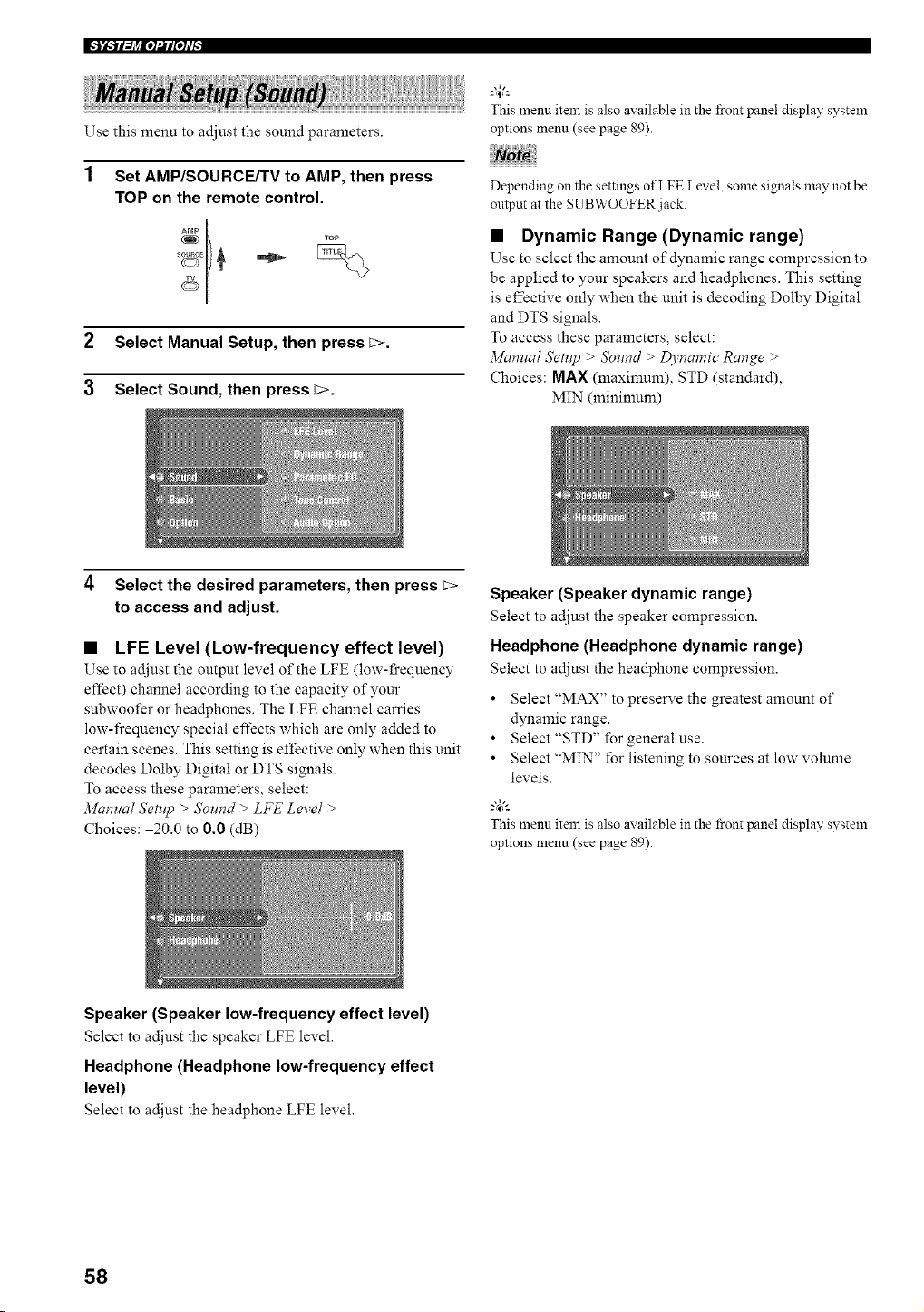
IFJ_TFIj_ioI_IPh'_
Use this menu to adjust the sound parameters.
1
Set AMP/SOURCE/TV to AMP, then press
TOP on the remote control.
2 Select Manual Setup, then press E>.
3 Select Sound, then press _.
_.,&
This menu item is also available in the front panel display system
options menu (see page 89).
Depending on the settings of LFE Level, some signals may not be
output at the SUBWOOFER jack.
• Dynamic Range (Dynamic range)
Use to select the amount of dynamic range compression to
be applied to your speakers and hea@hones. This setting
is effective only when the unit is decoding Dolby Digital
and DTS signals.
To access these parameters, select:
Manual Setup > Sound > Dynamic Range >
Choices: MAX (maximum), STD (standard),
MIN (minimum)
4 Select the desired parameters, then press _>
to access and adjust.
• LFE Level (Low-frequency effect level)
Use to adjust the output level of the LFE (low-frequency
effect) channel according to the capacity of your
subwoofer or headphones. The LFE channel carries
low-frequency special effects which are only added to
certain scenes. This setting is effective only when this unit
decodes Dolby Digital or DTS signals.
To access these parameters, select:
Manual Setnp > Sound > LFE Level >
Choices: 20.0 to 0.0 (dB)
Speaker (Speaker dynamic range)
Select to adjust the speaker compression.
Headphone (Headphone dynamic range)
Select to adjust the headphone compression.
• Select "MAX" to preserve the greatest amount of
dynamic range.
• Select "STD" for general use.
• Select "MIN" for listening to sources at low volume
levels.
_.,&
This menu item is also available in the front panel display system
options menu (see page 89).
Speaker (Speaker low-frequency effect level)
Select to adjust the speaker LFE level.
Headphone (Headphone low-frequency effect
level)
Select to adjust the headphone LFE level.
58
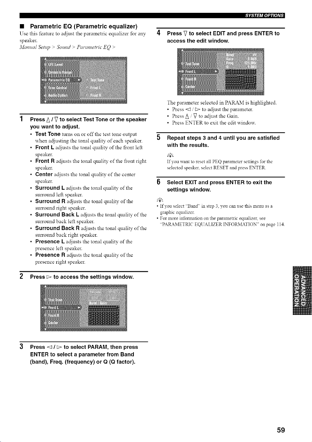
• Parametric EQ (Parametric equalizer)
Use this feature to adjust the parametric equalizer for any
speaker.
Manual Setup > Sound > Parametric EQ >
Press V to select EDIT and press ENTER to
access the edit window.
Press A / V to select Test Tone or the speaker
you want to adjust.
• Test Tone tunas on or offthe test tone output
when adjusting the tonal quality of each speaker.
Front L adjusts the tonal quality of the front left
speaker.
Front R adjusts the tonal quality of the fi'ont right
speaker.
Center adjusts the tonal quality of the center
speaker.
Surround L adjusts the tonal quality of the
sun'ound left speaker.
Surround R adjusts the tonal quality of the
sun'ound right speaker.
Surround Back L adjusts the tonal quality of the
sun'ound back left speaker.
Surround Back R adjusts the tonal quality of the
sun'ound back right speaker.
Presence [. adjusts the tonal quality of the
presence left speaker.
Presence R adjusts the tonal quality of the
presence right speaker.
2 Press _> to access the settings window.
The parameter selected in PARAM is highlighted.
• Press <3 / C> to adjust the parameter.
• Press/_ / V to adjust the Gain.
• Press ENTER to exit the edit window.
5 Repeat steps 3 and 4 until you are satisfied
with the results.
If you want to reset all PEQ parameter settings l\_r the
selected speaker, select RESET and press ENTER.
6 Select EXIT and press ENTER to exit the
settings window.
g4_'--
• If you select "Band' in step 3 you can use this menu as a
graphic equalizer.
• For more ini\mnation on the parametric equalizen see
"PARAMETRIC EQUALIZER INFORMATION" on page 114.
3 Press <l/E> to select PARAM, then press
ENTER to select a parameter from Band
(band), Freq. (frequency) or Q (Q factor).
59
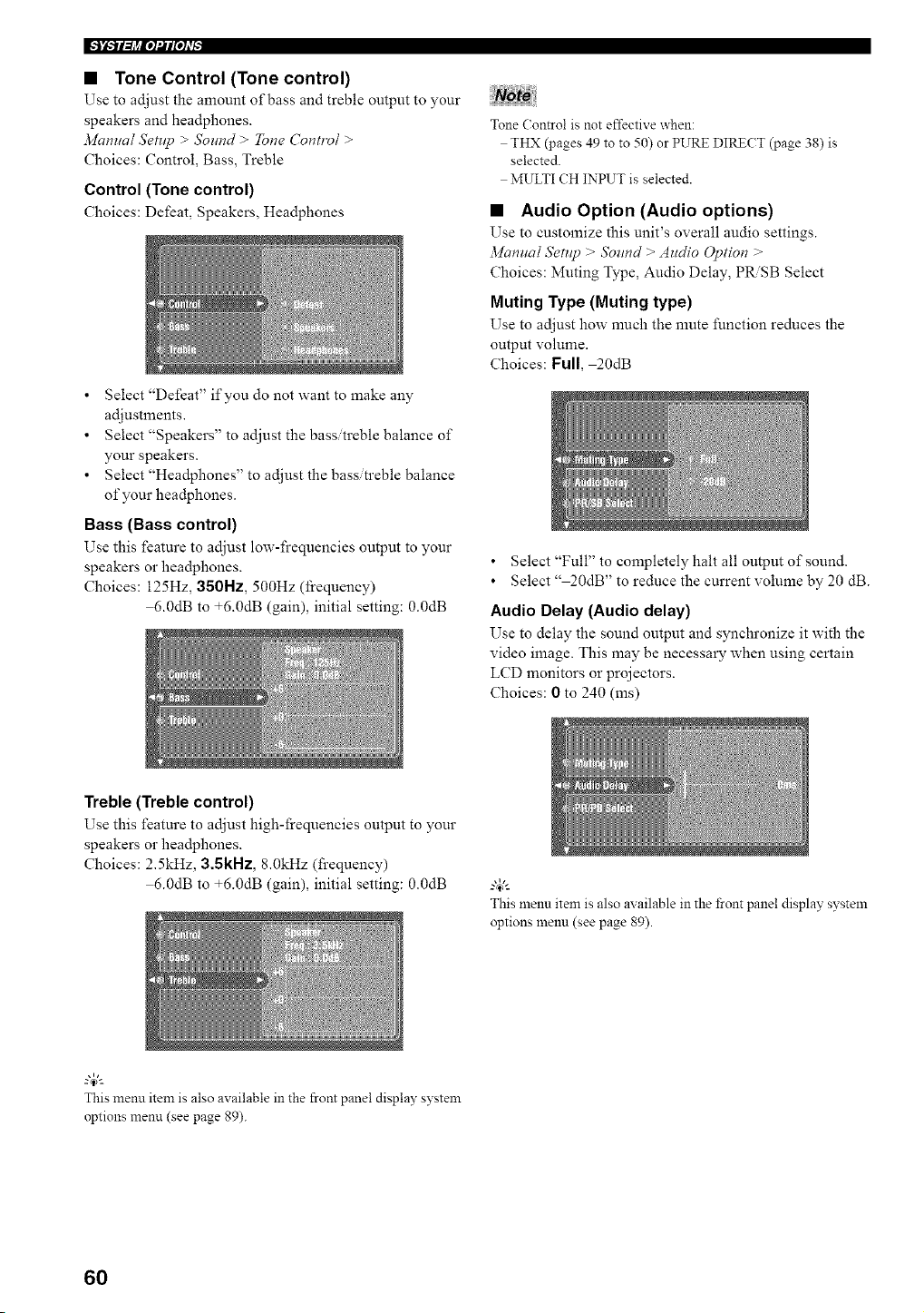
• Tone Control (Tone control)
Use to adjust the amount of bass and treble output to your
speakers and headphones.
Mamla/ Setnp > Sound > Tone Cont_v/ >
Choices: Control, Bass, Treble
Control (Tone control)
Choices: Defeat, Speakers, Headphones
• Select "Defeat" if you do not want to make any
adjustments.
• Select "Speakers" to adjust the bass/treble balance of
your speakers.
• Select "Headphones" to adjust the bass/treble balance
of your hea@hones.
Bass (Bass control)
Use this feature to adjust low-frequencies output to your
speakers or hea@hones.
Choices: 125Hz, 350Hz, 500Hz (frequency)
6.0dB to +6.0dB (gain), initial setting: 0.0dB
Tone Control is not effective when:
THX (pages 49 to to 50) or PURE DIRECT (page 38) is
selected.
MULTI CH INPUT is selected.
• Audio Option (Audio options)
Use to customize this unit's overall audio settings.
3/lunua/ SetHp > Sound > Audio @tion >
Choices: Muting Type, Audio Delay, PRiSB Select
Muting Type (Muting type)
Use to adjust how nmch the nmte function reduces the
output volume.
Choices: Full, 20dB
• Select "Full" to completely halt all output of sound.
• Select" 20dB" to reduce the current volume by 20 dB.
Audio Delay (Audio delay)
Use to delay the sound output and synchronize it with the
video image. This may be necessary when using certain
LCD monitors or projectors.
Choices: 0 to 240 (ms)
Treble (Treble control)
Use this feature to adjust high-frequencies output to your
speakers or hea@hones.
Choices: 2.5kHz, 3.5RHz, 8.0kHz (frequency)
6.0dB to +6.0dB (gain), initial setting: 0.0dB
This menu item is also available in the front panel display system
options 1hen1_1(see page 89).
This menu item is also available in the front panel display system
options menn (see page 89).
6O
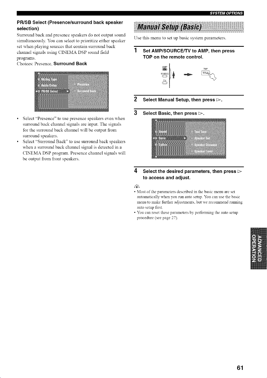
PR/SB Select (Presence/surround back speaker
selection)
Surround back and presence speakers do not output sound
simultaneously. You can select to prioritize either speaker
set when playing sources that contain surround back
channel signals using CINEMA DSP sound field
programs.
Choices: Presence, Surround Back
Use this menu to set up basic system parameters.
Set AMP/SOURCE/TV to AMP, then press
TOP on the remote control.
Select "Presence" to use presence speakers even when
surround back channel signals are input. The signals
for the surround back channel will be output from
surround speakers.
Select "Surround Back" to use surround back speakers
when a surround back channel signal is detected in a
CINEMA DSP program. Presence channel signals will
be output fi'om fi'ont speakers.
2 Select Manual Setup, then press _>.
3 Select Basic, then press _>.
4 Select the desired parameters, then press C>
to access and adjust.
• Most of the parameters described in the basic menu are set
automatically when you nm auto setup. You can use the basic
menu to make further acliustmeuts, but we reconmlend nmning
auto setup first.
• You can reset these parameters by perfomling the auto setup
procedure (see page 27).
61
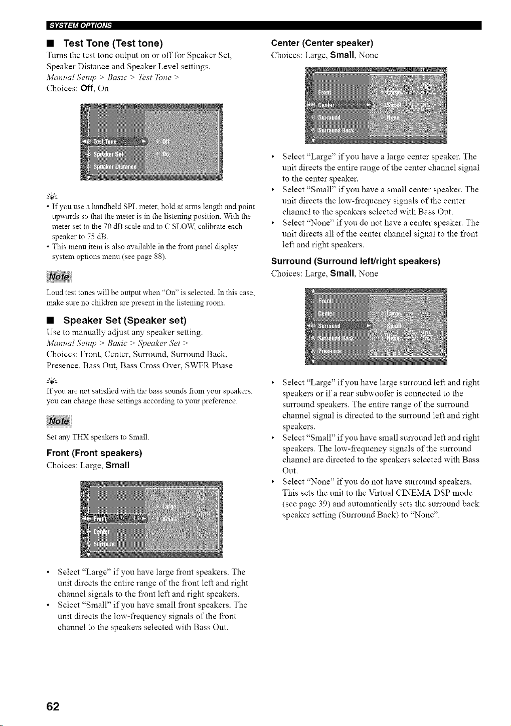
• Test Tone (Test tone)
Turns the test tone output on or off for Speaker Set,
Speaker Distance and Speaker Level settings.
Manual Setup > Basic > Test Tone >
Choices: Off, On
Center (Center speaker)
Choices: Large, Small, None
• If you use a handheld SPL meter, hold at amls length and point
upwards so that the meter is in the listening position. With the
meter set to the 70 dB scale and to C SLO\_2 calibrate each
speaker to 75 dB.
• This menu item is also available in the front panel display
system options menn (see page 88).
Loud test tones will be ontpm when "On" is selected. In this case.
make sure no children are present in the listening room.
• Speaker Set (Speaker set)
Use to manually adjust any speaker setting.
Manual SetHp > Basic > Speaker Set >
Choices: Front, Center, Surround, Surround Back,
Presence, Bass Out, Bass Cross Over, SWFR Phase
If yon are not satisfied with the bass sotmds from yottr speakers.
you can change these settings according to your preference.
Set any THX speakers to Small.
Front (Front speakers)
Choices: Large, Small
• Select "Large" if you have a large center speaker. The
unit directs the entire range of the center channel signal
to the center speaker.
• Select "Small" if you have a small center speaker. ]'he
unit directs the low-frequency signals of the center
channel to the speakers selected with Bass Out.
• Select "None" if you do not have a center speaker. The
unit directs all of the center channel signal to the front
left and right speakers.
Surround (Surround left/right speakers)
Choices: Large, Small, None
• Select "Large" if you have large surround left and right
speakers or if a rear subwoofer is connected to the
surround speakers. The entire range of the surround
channel signal is directed to the surround left and right
speakers.
• Select "Small" if you have small surround left and right
speakers. The low-frequency signals of the surround
channel are directed to the speakers selected with Bass
Out.
• Select "None" if you do not have surround speakers.
This sets the unit to the Virtual CINEMA DSP anode
(see page 39) and automatically sets the surround back
speaker setting (Surround Back) to "None".
Select "Large" if you have large front speakers. The
umt directs the entire range of the front left and right
channel signals to the front left and right speakers.
Select "Small" if you have small front speakers. ]'he
unit directs the low-frequency simaals of the front
channel to the speakers selected with Bass Out.
62
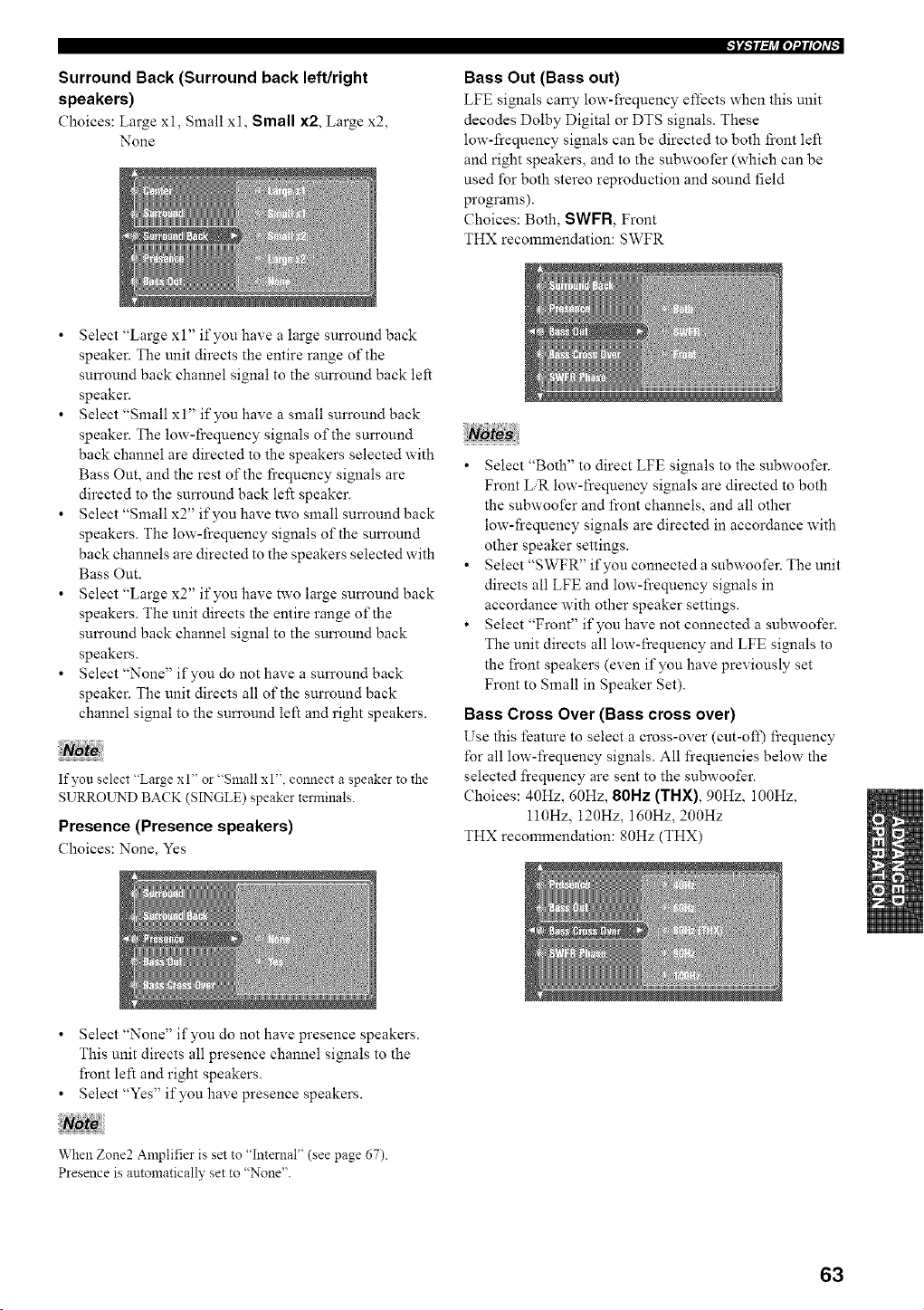
Surround Back (Surround back left/right
speakers)
Choices: Large xl, Small xl, Small x2, Large x2,
None
Bass Out (Bass out)
LFE signals carry low-frequency effects when this unit
decodes Dolby Digital or DTS signals. These
low-frequency signals can be directed to both front left
and right speakers, and to the subwoofer (which can be
used for both stereo reproduction and sound field
programs).
Choices: Both, SWFR, Front
THX recommendation: SWFR
Select "Large xl" if you have a large surround back
speaker. The unit directs the entire range of the
surround back channel signal to the surround back left
speaker.
Select "Small xl" if you have a small surround back
speaker. The low-frequency signals of the surround
back channel are directed to the speakers selected with
Bass Out, and the rest of the fi'equency signals are
directed to the surround back left speaker.
Select "Small x2" if you have two small surround back
speakers. The low-frequency signals of the surround
back channels are directed to the speakers selected with
Bass Out.
Select "Large x2" if you have two large surround back
speakers. The unit directs the entire range of the
surround back channel signal to the surround back
speakers.
Select "None" if you do not have a surround back
speaker. The unit directs all of the surround back
channel signal to the surround left and right speakers.
If you select "Large xl" or "Small xl", connect a speaker to the
SURROUND BACK (SINGLE) speaker terminals.
Presence (Presence speakers)
Choices: None, Yes
• Select "Both" to direct LFE signals to the subwoofer.
Front LR low-frequency signals are directed to both
the subwoofer and front channels, and all other
low-frequency signals are directed in accordance with
other speaker settings.
• Select "SWFR" if you connected a subwoofer. The unit
directs all LFE and low-frequency signals in
accordance with other speaker settings.
• Select "Front" if you have not connected a subwoofer.
The unit directs all low-frequency and LFE signals to
the front speakers (even if you have previously set
Front to Small in Speaker Set).
Bass Cross Over (Bass cross over)
Use this feature to select a cross-over (cut-oft) frequency
for all low-frequency signals. All frequencies below the
selected frequency are sent to the subwoofer.
Choices: 40Hz, 60Hz, 80Hz (THX), 90Hz, 100Hz,
ll0Hz, 120Hz, 160Hz, 200Hz
THX recommendation: 80Hz (THX)
Select "None" if you do not have presence speakers.
This unit directs all presence channel signals to the
front left and right speakers.
Select "Yes" if you have presence speakers.
When Zone2 Amplifier is set to "Internal" (see page 67),
Presence is automatically set to "None".
63
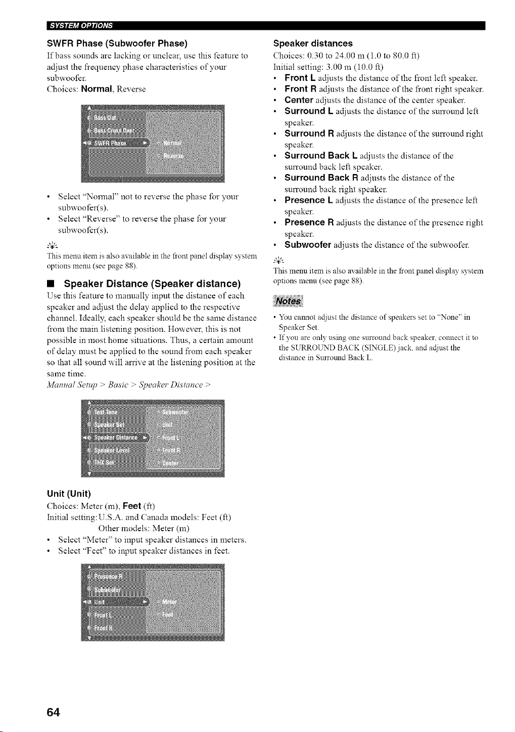
SWFR Phase (Subwoofer Phase)
If bass sounds are lacking or unclear, use this feature to
adjust the frequency phase characteristics of your
subwoofer.
Choices: Normal, Reverse
• Select "Normal" not to reverse the phase for your
subwoofer(s).
• Select "Reverse" to reverse the phase for your
subwoofer(s).
This menu item is also available in the front panel display system
options menu (see page 88).
• Speaker Distance (Speaker distance)
Use this feature to manually input the distance of each
speaker and adjust the delay applied to the respective
channel. Ideally, each speaker should be the same distance
from the main listening position. However, this is not
possible in most home situations. Thus, a certain amount
of delay must be applied to the sound from each speaker
so that all sound will an'ive at the listening position at the
same time.
Manual Setup > Basic > Speaker Distance >
Speaker distances
Choices: 0.30 to 24.00 m (1.0 to 80.0 ft)
Initial setting: 3.00 m (10.0 ft)
• Front L adjusts the distance of the front left speaker.
• Front R adjusts the distance of the front right speaker.
• Center adjusts the distance of the center speaker.
• Surround L adjusts the distance of the sun'ound left
speaker.
Surround R adjusts the distance of the surround right
speaker.
Surround Back L adjusts the distance of the
surround back left speaker.
Surround Back R adjusts the distance of the
surround back right speaker.
Presence L adjusts the distance of the presence left
speaker.
Presence R adjusts the distance of the presence right
speaker.
Subwoofer adjusts the distance of the subwoofer.
_.,#._
This menu item is also available in the front panel display system
options menu (see page 88).
• You caamot actiust the distance of speakers set to "None" in
Speaker Set.
• If you are only using one surround back speakec connect it to
the SURROUND BACK (SINGLE) jack, and ac[iust the
distance in Surrotmd Back L.
Unit (Unit)
Choices: Meter (m), Feet (ft)
Initial setting:U.S.A, and Canada models: Feet (fl)
Other models: Meter (m)
• Select "Meter" to input speaker distances in meters.
• Select "Feet" to input speaker distances in feet.
64
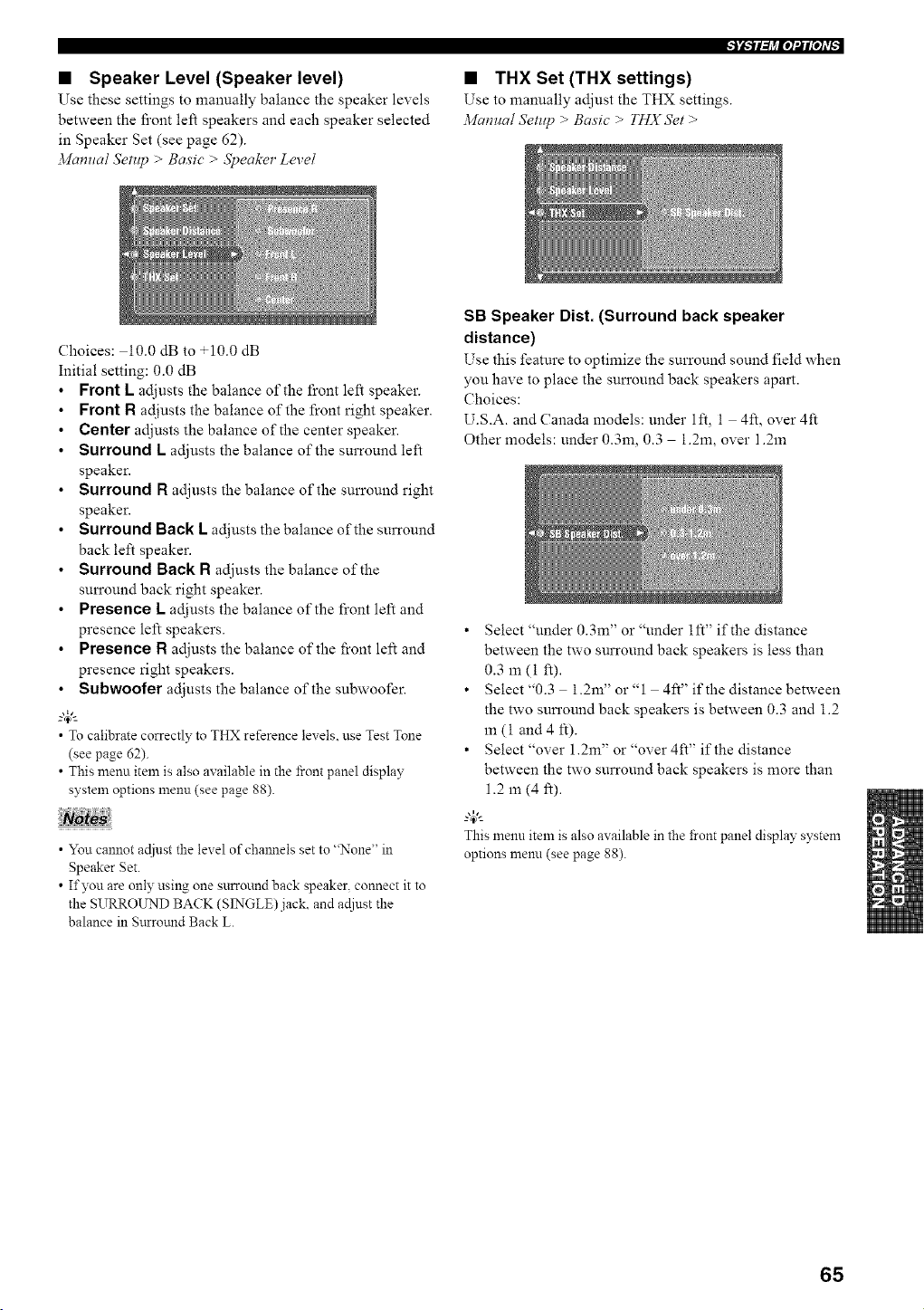
• Speaker Level (Speaker level)
Use these settings to manually balance the speaker levels
between the fi'ont left speakers and each speaker selected
in Speaker Set (see page 62).
Manual Setup > Basic > Speaker Level
• THX Set (THX settings)
Use to manually adjust the THX settings.
Manna[ Setup > Basic > FHX Set >
Choices: i0.0 dB to +10.0 dB
Initial setting: 0.0 dB
Front L adjusts the balance of the front left speaker.
Front R adjusts the balance of the front right speaker.
Center adjusts the balance of the center speaker.
Surround L adjusts the balance of the surround left
speaker.
Surround R adjusts the balance of the surround right
speaker.
Surround Back L adjusts the balance of the surround
back left speaker.
Surround Back R adjusts the balance of the
surround back right speaker.
Presence L adjusts the balance of the front left and
presence left speakers.
Presence R adjusts the balance of the front left and
presence right speakers.
Subwoofer adjusts the balance of the subwoofer.
_.,#._
• To calibrate correctly to THX reference levels, use Test Tone
(see page 62).
• This menu item is also available in the i]-ont panel display
system options menu (see page 88).
• You cannot adiust the level of chmmels set to "None" in
Speaker Set.
• If you are only using one surround back speaker, connect it to
the SURROUND BACK (SINGLE)jack, and adiust the
balance in Surromld Back L.
SB Speaker Dist. (Surround back speaker
distance)
Use this feature to optimize the surround sound field when
you have to place the surround back speakers apart.
Choices:
U.S.A. and Canada models: under 1ft, 1 4ft, over 4ft
Other models: under 0.3m, 0.3 1.2m, over 1.2m
• Select "under 0.3m" or "under lft" if the distance
between the two surround back speakers is less than
0.3 m (1 ft).
• Select"0.3 1.2m"or"l 4ft"ifthe distance between
the two surround back speakers is between 0.3 and 1.2
m (1 and 4 It).
• Select "over 1.2m" or "over 4ft" if the distance
between the two surround back speakers is more than
1.2 m (4 ft).
This menu item is also available in the i]-ont panel display system
options menu (see page 88).
65
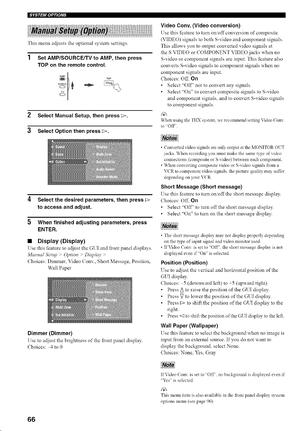
This menu adjusts the optional system settings.
1
Set AMP/SOURCE/TV to AMP, then press
TOP on the remote control.
2 Select Manual Setup, then press _>.
3 Select Option then press_>.
4 Select the desired parameters, then press C>
to access and adjust.
5 When finished adjusting parameters, press
ENTER.
• Display (Display)
Use this feature to adjust the GUI and front panel displays.
3/iamtal Setup > Optiot? > Display >
Choices: Dimmer, Video Conv., Short Message, Position,
Wall Paper
Dimmer (Dimmer)
Use to adjust the brightness of the fi'ont panel display.
Choices: 4 to 0
Video Conv. (Video conversion)
Use this feature to turn onoff conversion of composite
(VIDEO) signals to both S-video and component signals.
This allows you to output converted video signals at
the S VIDEO or COMPONENT VIDEO jacks when no
S-video or component signals are input. This feature also
converts S-video signals to component signals when no
component signals are input.
Choices: Off, On
• Select "OII _' not to convert any signals.
• Select "On" to convert composite signals to S-video
and component signals, and to convert S-video signals
to component signals.
g#-.
When using the THX system, we reconmaend setting Video Cony.
to "Off'.
• (onverted video signals are only output at the MONITOR OUT
jacks. When recording you ml_lStmake the same type of video
connectmns (composite or S-video) between each component.
• When converting composite video or S-video signals t'rona a
VCR to component video signals the picture quality may suffer
depending on your VCR.
Short Message (Short message)
Use this feature to turn onoff the short message display.
Choices: Off, On
• Select "OfP' to turn off the short message display.
• Select "On" to tuna on the short message display.
• The short message display may not display properly depending
on the type of input signal and video monitor used.
• If Video Cony. is set to "Oft", the short message display is not
displayed even it""On" is selected.
Position (Position)
Use to adjust the vertical and horizontal position of"the
GUI display.
Choices: 5 (downward.left) to +5 (upward'right)
• Press/_ to raise the position of the GUI display.
• Press V to lower the position of the GUI display.
• Press C> to shift the position of the GUI display to the
right.
• Press <1 to shift the position of the GUI display to the left.
Wall Paper (Wallpaper)
Use this feature to select the background when no image is
input from an external source. If you do not want to
display the background, select None.
Choices: None, Yes, Gray
If Video Cony. is set to "Off'. no backgrotmd is displayed even if
"Yes" is selected.
_-'#-
Thismenu item is also available in the front panel display system
options menu (see page 90).
66
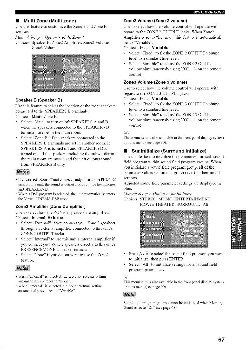
• Multi Zone (Multi zone)
Use this feature to customize the Zone 2 and Zone B
settings.
Manual Setup > @tion > )vllt/ti Zone >
Choices: Speaker B, Zone2 Amplifier, Zone2 Volmne,
Zone3 Volume
Speaker B (Speaker B)
Use this feature to select the location of the fi'ont speakers
connected to the SPEAKERS B terminals.
Choices: Main, Zone B
Select "Main" to turn on/off SPEAKERS A and B
when the speakers connected to the SPEAKERS B
terminals are set in the main room.
Select "Zone B" if the speakers connected to the
SPEAKERS B terminals are set in another room. If
SPEAKERS A is tumed off and SPEAKERS B is
turned on, all the speakers including the subwoofer in
the main room are nmted and the unit outputs sound
fi'om SPEAKERS B only.
• If you select "Zone B" and connect headphones to the PHONES
jack on this mlit. the sound is output from both the headphones
and SPEAKERS B.
• When a DSP program is selected, the unit antomatically enters
the Virtual CINEMA DSP mode.
Zone2 Amplifier (Zone 2 amplifier)
Use to select how the ZONE 2 speakers are amplified.
Choices: Internal, External
Select "External" if you connect your Zone 2 speakers
through an external amplifier connected to this unit's
ZONE 2 OUTPUT jacks.
Select "Internal" to use this unit's internal amplifier if
you connect your Zone 2 speakers directly to this unit's
PRESENCE/ZONE 2 speaker terminals.
Select "None" if you do not want to use the Zone2
feature.
• When "Intenlal" is selected, the presence speaker setting
automatically switches to "None".
• When "Internal" is selected, the Zone2 volume setting
automatically switches to "\_ariable".
Zone2 Volume (Zone 2 volume)
Use to select how the volume control will operate with
regard to the ZONE 2 OUTPUT jacks. When Zone2
Amplifier is set to "Internal", this feature is automatically
set to "Variable".
Choices: Fixed, Variable
• Select "Fixed" to fix the ZONE 2 OUTPUT volume
level to a standard line level.
• Select "Variable" to adjust the ZONE 2 OUTPUT
volume simultaneously using VOL +M on the remote
control.
Zone3 Volume (Zone 3 volume)
Use to select how the volume control will operate with
regard to the ZONE 3 OUTPUT jacks.
Choices: Fixed, Variable
• Select "Fixed" to fix the ZONE 3 OUTPUT volume
level to a standard line level.
• Select "Variable" to adjust the ZONE 3 OUTPUT
volume simultaneously using VOL + on the remote
control.
This menu item is also available in the front panel display system
options menu (see page 90).
• Sur.lnitialize (Surround initialize)
Use this feature to initialize the parameters for each sound
field program within sound field program groups. When
you initialize a sound field program group, all of the
parameter values within that group revert to their initial
settings.
Adjusted sound field parmneter settings are displayed in
blue.
.'viun_tal Setup > @tion > Sin:Initialize
Choices: STEREO, MUSIC, ENTERTAINMENT,
MOVIE THEATER, SURROUND, All
• Press A / V to select the sound field program you want
to initialize, then press ENTER.
• Select "All" to initialize settings Ibr all sound field
program parameters.
g4_"-
This menu item is also available in the front panel display system
options menn (see page 90).
Sound field program _-oups cannot be initialized when Memory
Guard is set to "On" (see page 68).
67
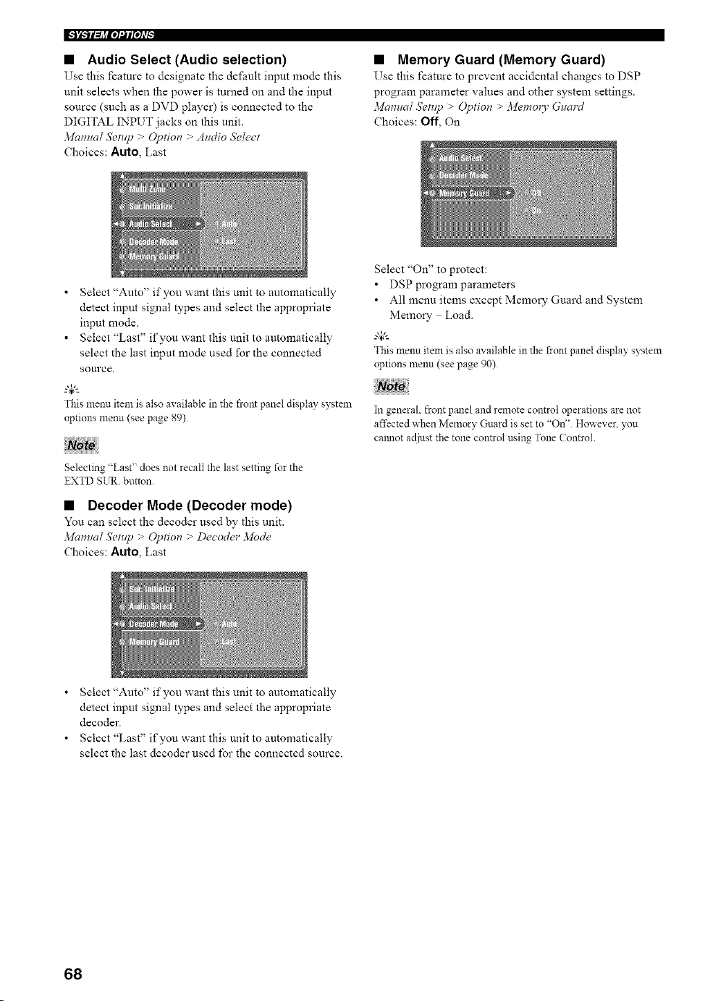
IFJ_TFh_iol_l_oh'_
• Audio Select (Audio selection)
Use this feature to designate the default input mode this
unit selects when the power is turned on and the input
source (such as a DVD player) is connected to the
DIGITAL INPUT jacks on this unit.
Mamlal Setllp > @tion > Audio Select
Choices: Auto, Last
• Memory Guard (Memory Guard)
Use this feature to prevent accidental changes to DSP
program parameter values and other system settings.
Manual Setllp > @tiot_ > ]viemo_ 3" Guard
Choices: Off', On
• Select "Auto" if you want this unit to automatically
detect input signal types and select the appropriate
input mode.
• Select "Last" if you want this unit to automatically
select the last input mode used for the connected
source.
This menn item is also available in the front panel display system
options menu (see page 89).
Selecting "Last" does not recall the last setting for the
EXTD SUR. button.
• Decoder Mode (Decoder mode)
You can select the decoder used by this unit.
Ma,ual SetHp > @rio, > Decoder 3/lode
Choices: Auto, Last
Select "On" to protect:
• DSP program parameters
• All menu items except Memory Guard and System
Memory Load.
_.,#._
This menu item is also available in the front panel display system
options menu (see page 90).
In general, front panel and remote control operations are not
affected when Memory Guard is set to "On". However you
cmmot acliust the tone control using Tone Control.
• Select "Auto" if you want this unit to automatically
detect input signal types and select the appropriate
decoder.
• Select "Last" if you want this unit to automatically
select the last decoder used for the connected source.
68
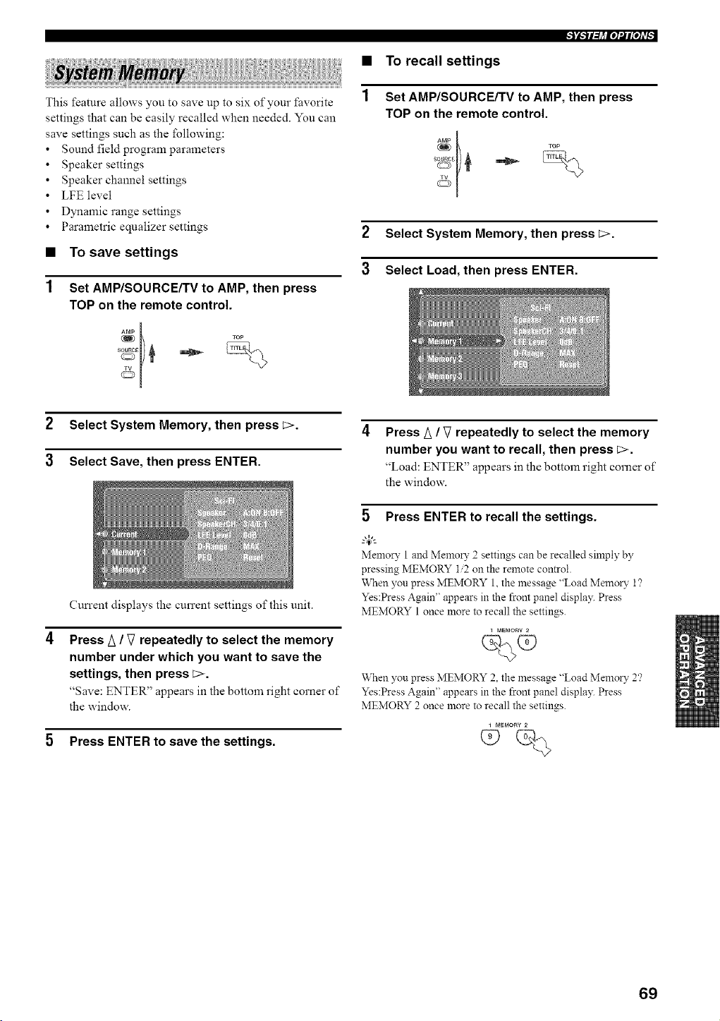
This feature allows you to save up to six of your favorite
settings that can be easily recalled when needed. You can
save settings such as the following:
Sound field program parameters
Speaker settings
Speaker channel settings
LFE level
Dynamic range settings
Parametric equalizer settings
• To save settings
Set AMP/SOURCE/TV to AMP, then press
TOP on the remote control.
+++
++
2 Select System Memory, then press L>.
3 Select Save, then press ENTER.
Cun'ent displays the current settings of this unit.
Press A / V repeatedly to select the memory
number under which you want to save the
settings, then press c>.
"Save: ENTER" appears in the bottom right corner of
the window.
5 Press ENTER to save the settings.
li-ll-tJ_iq_lPJfi,
• To recall settings
1 Set AMP/SOURCE/TV to AMP, then press
TOP on the remote control.
AmP
TOP
&
2 Select System Memory, then press C>.
3 Select Load, then press ENTER.
Press/_ / V repeatedly to select the memory
number you want to recall, then press _>.
"Load: ENTER" appears in the bottom right corner of
the window.
5 Press ENTER to recall the settings.
Melnory 1 and Memory 2 settings can be recalled simply by
pressing MEMORY 12 on the remote control.
When you press MEMORY 1, the message "Load Memory 1?
Yes:Press Again" appears in the front panel display. Press
MEMORY 1 once more to recall the settings.
i MEMOR'¢
When you press MEMORY 2, the message "Load Memory 2'?
Yes:Press Again" appears in the front panel display. Press
MEMORY 2 once more to recall the settings.
69
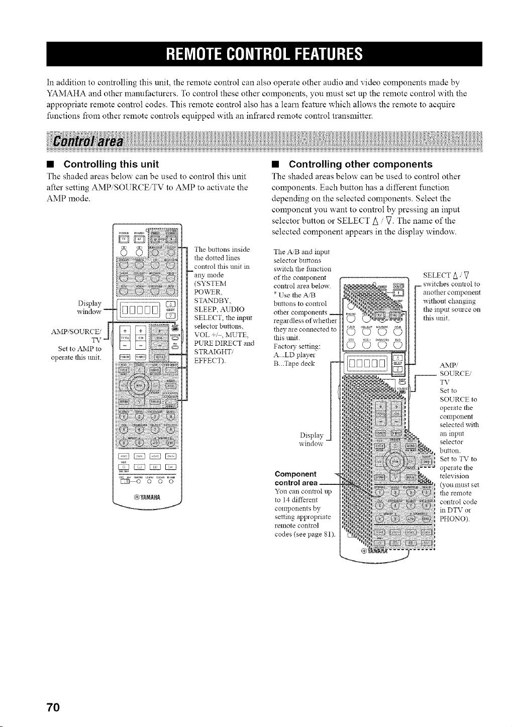
In addition to controlling this unit, the remote control can also operate other audio and video components made by
YAMAHA and other manufacturers. To control these other components, you must set up the remote control with the
appropriate remote control codes. This remote control also has a learn feature which allows the remote to acquire
functions from other remote controls equipped with an infrared remote control transmitter.
• Controlling this unit
The shaded areas below can be used to control this unit
after setting AMP/SOURCE, TV to AMP to activate the
AMP mode.
Display
window --
The buttons inside
the dotted lines
control this unit in
--any mode
(SYSTEM
POWER,
STANDBY,
SLEEP, AUDIO
SELECT, the input
selector buttons
VOL +', MUTE,
PURE DIRECT and
STI_MGHTi
EFFECT).
AMP/SOURCE/
TV-
Set to A_kIP to
operate this unit
• Controlling other components
The shaded areas below can be used to control other
components. Each button has a different function
depending on the selected components. Select the
component you want to control by pressing an input
selector button or SELECT A / V. The name of the
selected component appears in the display window.
The A/B and inpm
selector buttons
switch the fimction
of the component
cont!ol area below
* Use the AiB
buttons to control
other components __
regardless of whether
Display
window -
Component
control area --
"_bucan control up
to 14 different
components by
setting appropriate
relllote control
codes (see page 81)
SELECT A / 7
= switches control to
anothei colnponent
without changing
the input somce on
this unit.
AMP/
__ SOURCE/
TV
Set to
SOURCE to
operate the
COllllJonent
selected with
an input
selector
button.
Set to TV to
operate the
television
(you must set
the remote
cont!ol code
in DTV or
PHONO)
70
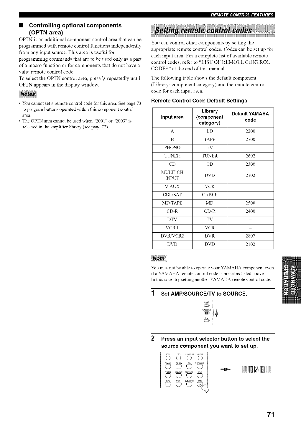
• Controlling optional components
(OPTN area)
OPTN is an additional component control area that can be
programmed with remote control functions independently
from any input source. This area is useful for
programming commands that are to be used only as a part
of a macro function or for components that do not have a
valid remote control code.
To select the OPTN control area, press V repeatedly until
OPTN appears in the display window.
• You cannot set a remote control code for this area. See page 73
to pro_aln buttons operated within this component control
area.
• The OPTN area cannot be used when "2001" or "2003" is
selected in the amplifier library (see page 72).
:I:/j_[OJI:I_roI=TII:{O]U#:r__|II]:/#,;
You can control other components by setting the
appropriate remote control codes. (?odes can be set up for
each input area. For a complete list of available remote
control codes, refer to "LIST OF REMOTE CONTROL
CODES" at the end of this manual.
The following table shows the default component
(Library: component category) and the remote control
code for each input area.
Remote Control Code Default Settings
Library Default YAMAHA
Input area (component code
category)
A LD 2200
B TAPE 2700
PHONO TV
TL_rNER TLrNER 2602
CD CD 2300
MULTI CH
DVD 210g
INPUT
V-AUX VCR
CBL SAT CABLE
MDiTAPE MD 2500
CD-R (D-R 2400
DTV TV
VCR 1 VCR
DVR&TCR2 DVR 2807
DVD DVD 2102
You 1nay not be able to operate )'our YAMAHA component even
if a YAMAHA remote control code is preset as listed above.
In this case. try setting another YAMAHA remote control code.
Set AMP/SOURCE/TV to SOURCE.
Press an input selector button to select the
source component you want to set up.
71
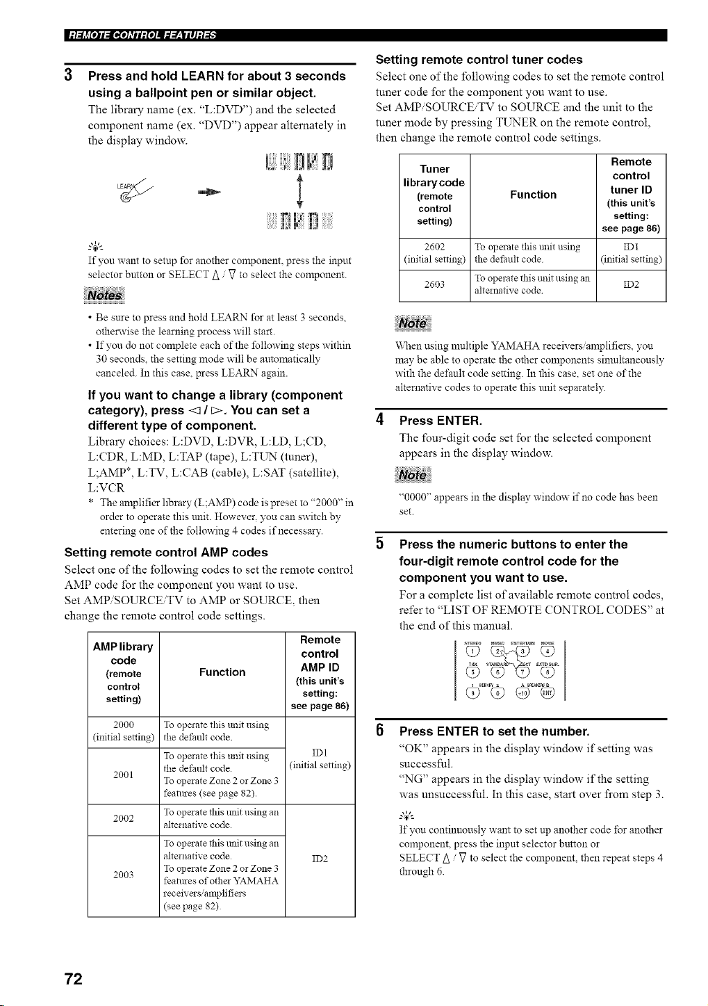
l:/:h_[o]l:lgO]dll:{o]ll=:Y__lll]:l-'_"
Press and hold LEARN for about 3 seconds
using a ballpoint pen or similar object.
The library name (ex. "L:DVD") and the selected
component name (ex. "DVD") appear alternately in
the display window.
D
;IAI fl ;i;;i l
--'4_'--
If yon want to setup for another component, press the input
selector button or SELECT A / V to select the component.
• Be sure to press and hold LEARN for at least 3 seconds
otherwise the learningprocess will start.
• If you do not complete each of the following stepswithin
30 seconds the setting mode will be automatically
canceled. In this case. press LEARN again.
If you want to change a library (component
category), press <1 / C>. You can set a
different type of component.
Library choices: L:DVD, L:DVR, L:LD, L;CD,
L:CDR, L:MD, L:TAP (tape), L:TUN (tuner),
L;AMP*, L:TV, L:CAB (cable), L:SAT (satellite),
L:VCR
* The amplifierlibrary (L;AMP) code ispreset to "2000" in
order to operate this unit. However, you can switch by
enteringone of the following 4 codes if necessary.
Setting remote control AMP codes
Select one of the following codes to set the remote control
AMP code for the component you want to use.
Set AMPiSOURCEiTV to AMP or SOURCE, then
change the remote control code settings.
AMP library
code
(remote
control
setting)
2000
(initial setting)
2001
2O02
2003
Function
To operate this unit using
the defimlt code.
To operate this unit using
the default code.
To operate Zone 2 or Zone 3
features (see page 82).
To operate this trait using an
alternative code.
To operate this trait using an
alternative code.
To operate Zone 2 or Zone 3
featmes of other YAMAHA
receivers/amplifiers
(see page 82)
Remote
control
AMP ID
(this unit's
setting:
see page 86)
IDI
(initial setting)
ID2
Setting remote control tuner codes
Select one of the following codes to set the remote control
tuner code for the component you want to use.
Set AMPiSOURCEiTV to SOURCE and the unit to the
tuner mode by pressing TUNER on the remote control,
then change the remote control code settings.
Remote
Tuner
control
librarycode tuner ID
(remote Function
control (this unit's
setting) setting:
see page 86)
2602 To operate _is unit using ID1
(initial setting) the det:ault code (initial setting)
2603 To operate this unit using an ID2
alternative code
When using multiple YAMAHA receivers/amplifiers, you
may be able to operate the other components simultaneously
with the default code setting. In this case, set one of the
alternative codes to operate this unit separately.
Press ENTER.
The lbur-digit code set for the selected component
appears in the display window.
"0000" appears in the display window if no code has been
set.
Press the numeric buttons to enter the
four-digit remote control code for the
component you want to use.
For a complete list of available remote control codes,
refer to "LIST OF REMOTE CONTROL CODES" at
the end of this manual.
Press ENTER to set the number.
"OK" appears in the display window if setting was
successful.
"NG" appears in the display window if the setting
was unsuccesslM. In this case, start over from step 3.
_.,#._
If you continuously want to set up another code for another
component, press the input selector button or
SELECT A / V to select the component, then repeat steps 4
through 6.
72
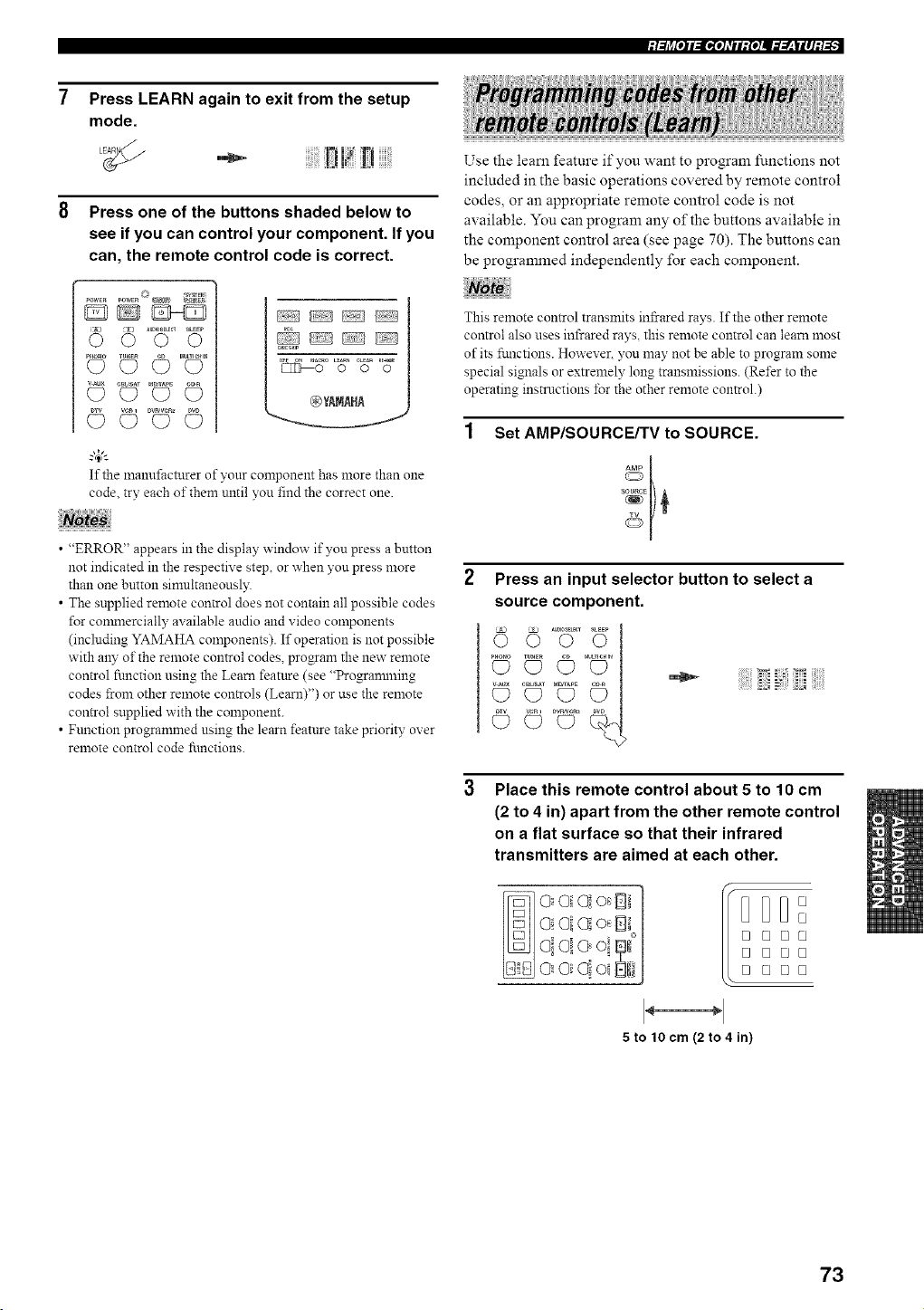
Press LEARN again to exit from the setup
mode.
!!!! [i
Press one of the buttons shaded below to
see if you can control your component. If you
can, the remote control code is correct.
DD_D
AUDIOSE_C__EEP
86oo
©
g_
If the manufi_cturer of your component has more than one
code try each of them until you find the correct one.
• "ERROR" appears in the display window if you press a button
not indicated in the respective step, or when you press more
than one button simultaueously.
• The supplied remote control does not contain all possible codes
for commercially available audio and video components
(including YAMAHA components). If operation is not possible
with any of the remote control codes, program the new remote
control function using the Learn feature (see "Progranmling
codes from other remote controls (Learn)") or use the remote
control supplied with the component.
• Function programmed using the learn feature take priority over
remote control code fi.mctions.
Use the learn feature if you want to program _%nctions not
included in the basic operations covered by remote control
codes, or an appropriate remote control code is not
available. You can program any of the buttons available in
the component control area (see page 70). The buttons can
be programmed independently for each component.
This remote control transmits infrared rays. If the other remote
control also uses infrared rays, this remote control can learn most
of its fi.mctions. However. you may not be able to program some
special signals or extremely long transmissions. (Refer to the
operating instructions for the other remote control.)
Set AMP/SOURCE/TV to SOURCE.
Press an input selector button to select a
source component.
5
Place this remote control about 5 to 10 cm
(2 to 4 in) apart from the other remote control
on a flat surface so that their infrared
transmitters are aimed at each other.
DDD°
o
o oo°
o ooo
o ooo
5 to 10 cm (2 to 4 in)
73
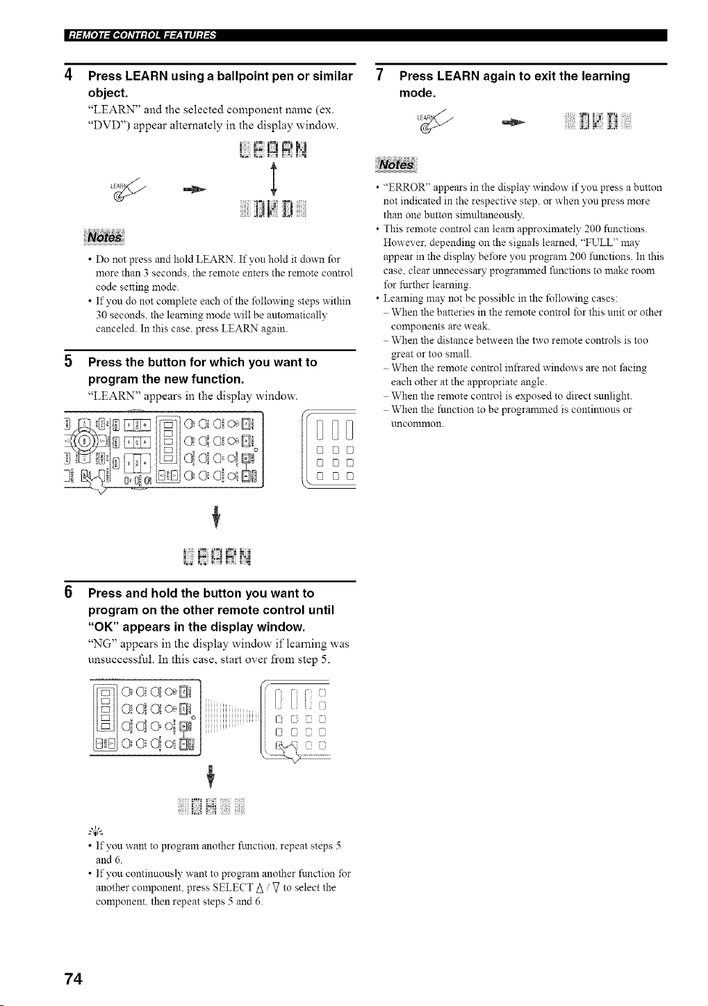
|:/.._j_[O]I_[I,[OATII:{O]I_._.___|II]:/-'_"
Press LEARN using a ballpoint pen or similar
object.
"LEARN" and the selected component name (ex.
"DVD") appear alternately in the display window.
I!IR
If i!
? tes
• Do not press and hold LEARN. If you hold it down for
more than 3 seconds, the remote enters the remote control
code setting mode.
• If you do not complete each of the following steps within
30 seconds, the learning mode will be automatically
canceled. In this case. press LEARN again.
Press the button for which you want to
program the new function.
"LEARN" appears in the display window.
Press LEARN again to exit the learning
mode.
• "ERROR" appears in the display window if yon press a bntton
not indicated in the respective step, or when you press more
than one button sinmltaneously.
• This remote control can learn approximately 200 functions.
However. depending on the signals learned, "FULL" may
appear in the display bd%re yon pro_am 200 functions. In this
case. clear unnecessary progranmled functions to make room
for ffzrther learning.
• Learning may not be possible in the following cases:
When the batteries in the remote control for this unit or other
components are weak.
When the distance between the two remote controls is too
great or too small.
When the remote control infrared windows are not facing
each other at the appropriate angle.
When the remote control is exposed to direct sunlight.
When the fnnction to be progrannned is continuous or
uncommon.
Press and hold the button you want to
program on the other remote control until
"OK" appears in the display window.
"NG" appears in the display window if lem'ning was
unsuccessful. In this case, start over from step 5.
O!Oi Ol o_Ill
oi@ ' °
O0q _fi
o eloiif
r'i i
g4_'--
• If you want to program another ftmction, repeat steps 5
and 6.
• If you continuously want to program another function for
another component, press SELECT A V to select the
component, then repeat steps 5 and 6.
74
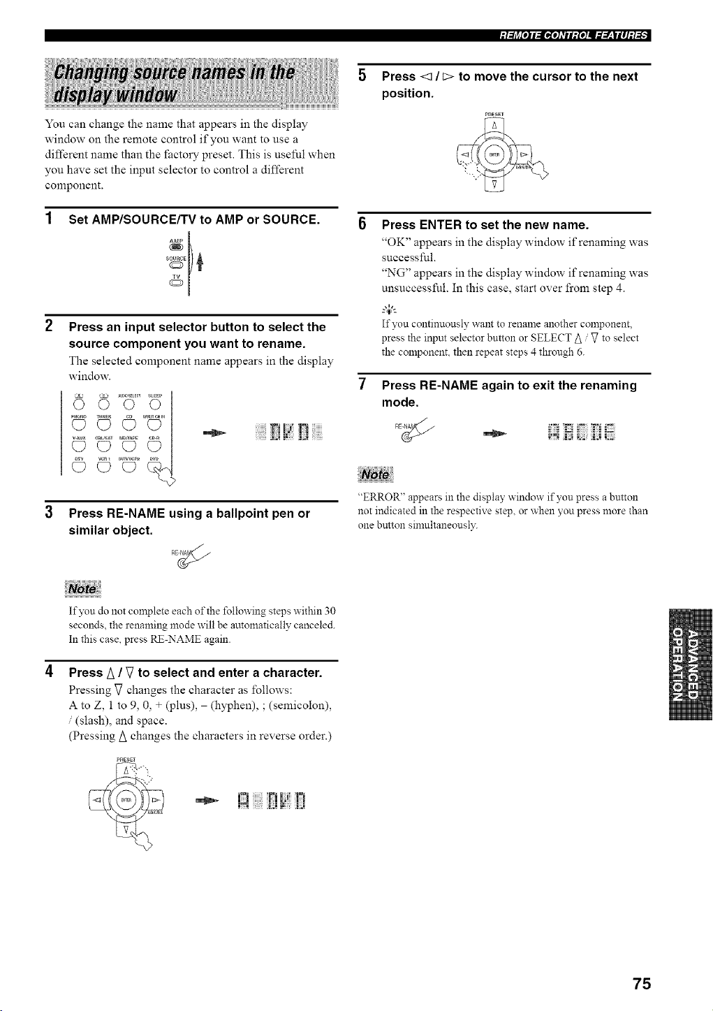
You can change the nmne that appears in the display
window on the remote control if you want to use a
different name than the factory preset. This is useful when
you have set the input selector to control a different
component.
Set AMP/SOURCE/TV to AMP or SOURCE.
Press an input selector button to select the
source component you want to rename.
The selected component name appears in the display
window.
Press RE-NAME using a ballpoint pen or
similar object.
Press <1 / c> to move the cursor to the next
position.
P_ESST
Press ENTER to set the new name.
"OK" appears in the display window if renaming was
successful.
"NG" appears in the display window if renaming was
unsuccessful. In this case, start over from step 4.
If you continuously want to rename another component.
press the input selector button or SELECT _ / V to select
the component, then repeat steps4 through 6.
Press RE-NAME again to exit the renaming
mode.
"ERROR" appears in the display window if you press a button
not indicated in the respective step, or when you press more than
one button silnultaneousl3:
If yon do not complete each of the following steps within 30
seconds, the renaming mode will be automatically canceled.
In this case, press RE-NAME again.
Press A / V to select and enter a character.
Pressing V changes the character as follows:
A to Z, 1 to 9, 0, + (plus), (hyphen), ; (semicolon),
/ (slash), and space.
(Pressing A changes the characters in reverse order.)
•_ !;] F[ !7
75
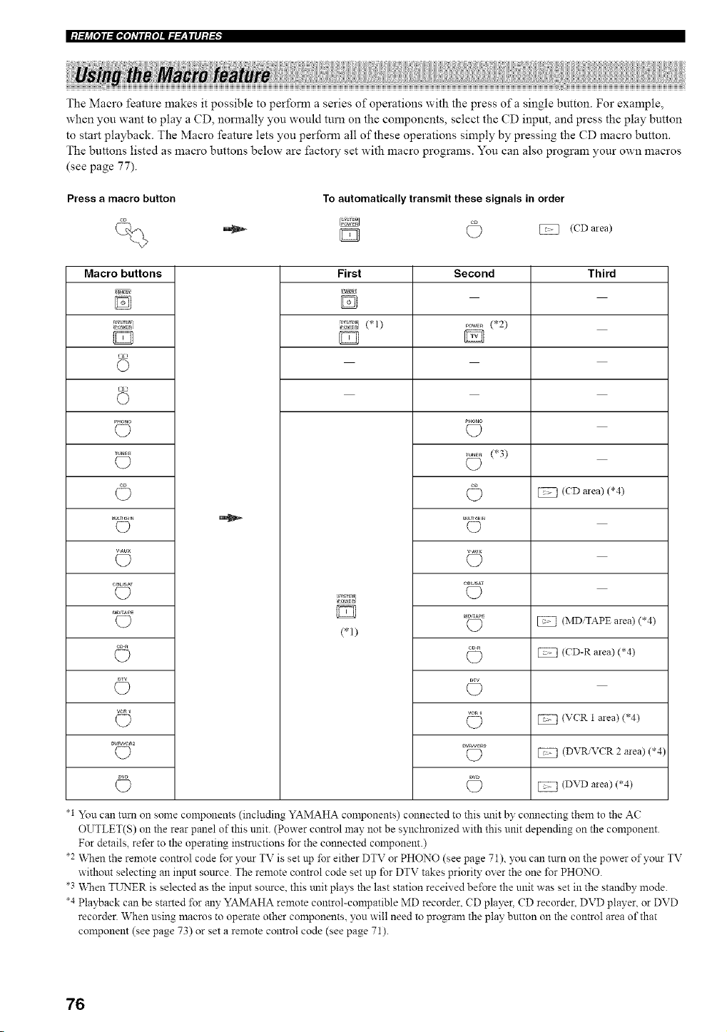
|:t.._j_[O]I_[I,[O]_TII:{O]II._.__,IlI]:I-'_"
The Macro feature makes it possible to perform a series of operations with the press of a single button. For example,
when you want to play a CD, normally you would turn on the components, select the CD input, and press the play button
to start playback. The Macro feature lets you perform all of these operations simply by pressing the CD macro button.
The buttons listed as macro buttons below are i_aetow set with macro programs. You can also program your own macros
(see page 77).
Press a macro button
To automatically transmit these signals in order
(CD mea)
Macro buttons
'A
O
C?
TUNE_
O
_u_nc_lN
O
v-Au×
(D
eB_SAT
(D
MD_APE
O
veRl
O
O
First
D
,_i (*1)
Pow_N
(*1)
Second
...... (*2)
PHOHO
O
...... (*3)
_I_LTr_IN
(D
v._ux
C)
c_sA_
C)
O
©
O
C)
Third
(CD area) (*4)
(MDiTAPE area) (*4)
(CD-R area) (*4)
(VCR 1 area) (*4)
(DVR/VCR 2 area) (*4)
(DVD area) (*4)
*1 You can turn on some components (including YAMAHA components) connected to this trait by connecting them to the AC
OUTLET(S) on the rear panel of this unit. (Power control may not be synchronized with this unit depending on the component.
For details, refer to the operating instructions for the connected component.)
*2 When the remote control code for your TV is set np for either DTV or PHONO (see page 71), you can turn on the power ofyonr TV
without selecting an input source. The remote control code set up for DTV takes priority over the one for PHONO.
*3 When TUNER is selected as the input source, this trait plays the last station received be±\_rethe unit was set in the standby mode.
"4 Playback can be started *br any YAMAHA remute control-compatible MD recorder. CD player. CD recorder. DVD player, or DVD
recorder. When using macros to operate other components, you will need to progran_ the play button on the control area of that
component (see page 73) or set a remote control code (see page 71).
76
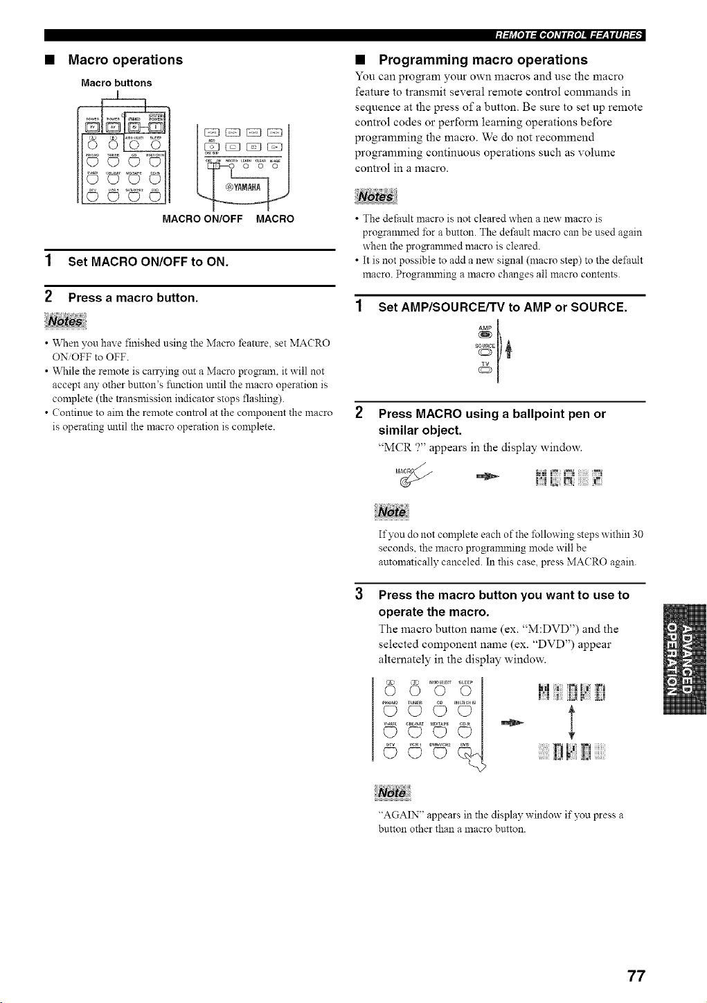
• Macro operations
Macro buttons
[
MACRO ON/OFF MACRO
1 Set MACRO ON/OFF to ON.
2 Press a macro button.
• When you have finished using the Macro feature, set MACRO
ON/OFF to OFF+
• While the remote is carrying out a Macro pro_am, it will not
accept any other button's flmction until the macro operation is
complete (the transmission indicator stops flashing).
• (ontinue to aim the remote control at the component the macro
is operating tmtil the macro operation is complete.
• Programming macro operations
You can pro_'am your own macros and use the macro
feature to transmit several remote control commands in
sequence at the press of a button. Be sure to set up remote
control codes or perform leaming operations before
programming the macro. We do not recommend
programming continuous operations such as volume
control in a macro.
• The default macro is not cleared when a new macro is
programmed for a button. The default macro can be used again
when the pro_annned macro is cleared.
• It is not possible to add a new signal (macro step) to the dd'ault
macro. Progranmling a macro changes all macro contents.
Set AMP/SOURCE/TV to AMP or SOURCE.
+[
Press MACRO using a ballpoint pen or
similar object.
"MCR ?" appears in the display window.
If you do not complete each of the ±Bllowing steps within 30
seconds, the macro progrannning mode will be
automatically canceled. In this case, press MACRO again.
Press the macro button you want to use to
operate the macro.
The macro button name (ex. '+M:DVD") and the
selected component name (ex. "DVD") appear
alternately in the display window.
o _ :+ g •
© © [!
"AGAIN" appears in the display window if you press a
button other than a macro button.
77
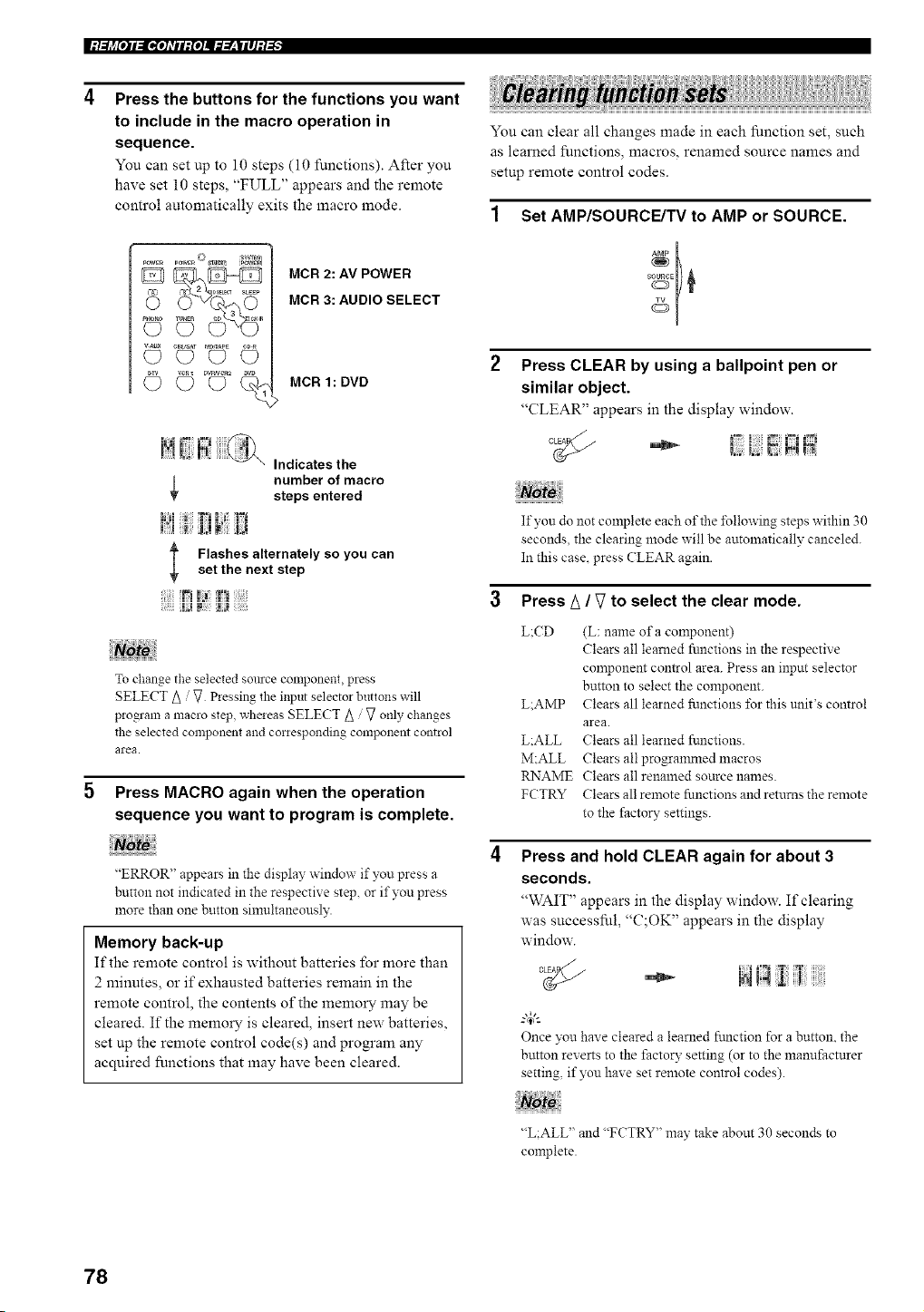
|:t.._j_[O]I_[I,[O]_TII:{O]II._.__,IlI]:I-'_"
Press the buttons for the functions you want
to include in the macro operation in
sequence.
You can set tip to 10 steps (10 functions). After you
have set 10 steps, "FULL" appears and the remote
control automatically exits the macro mode.
vAux e_us_ UP.APE
MCR 2: AV POWER
MCR 3: AUDIO SELECT
MCR 1: DVD
Indicates the
number of macro
steps entered
l;;;I |! 7m_
l Flashes alternately so you canset the next step
I_I Iii
To change the selected source component, press
SELECT A / V Pressing the input selector buttons will
program a macro step, wheleas SELECT A / V only changes
the selected component and corresponding component control
area.
Press MACRO again when the operation
sequence you want to program is complete.
Note
<'ERROR" appears in the display window if you press a
button not indicated in the respectix e step, or if you press
more than one button sinmltaneously.
Memory back-up
If the remote control is without batteries for more than
2 minutes, or if exhausted batteries remain in the
remote control, the contents of the memory may be
cleared. If the memory is cleared, insert new batteries,
set up the remote control code(s) and program any
acquired functions that may have been cleared.
You can clear all changes made in each function set, such
as learned functions, macros, renamed source names and
setup remote control codes.
Set AMP/SOURCE/TV to AMP or SOURCE.
Press CLEAR by using a ballpoint pen or
similar object.
'_CLEAR" appears in the display window.
If yon do not complete each of the *Mlowing steps within 30
seconds, the clearing mode x_ill be automatically canceled.
In this case. press CLEAR again.
3 Press A / _ to select the clear mode.
L:CD
L:AMP
L:ALL
M:ALL
RNAME
FCTRY
(L: name of a component)
Clears all learned fnnctions in the respective
component control area. Press an input selector
button to select the component.
Clears all learned functions ±\_rthis unit's control
area.
Clears all learned functions.
Clears all progrannned macros
Clears all renamed source names.
Clears all remote functions and returns the remote
to the factory settings.
Press and hold CLEAR again for about 3
seconds.
'_WAIT" appears in the display window. If clearing
was successful, "C;OK" appears in the display
window.
Once you have cleared a learned fm_ction for a button, the
button reverts to the factory setting (or to the manufacturer
setting, if you have set remote control codes).
"L;ALL" and "FCTRY" may take about 30 seconds to
complete.
78
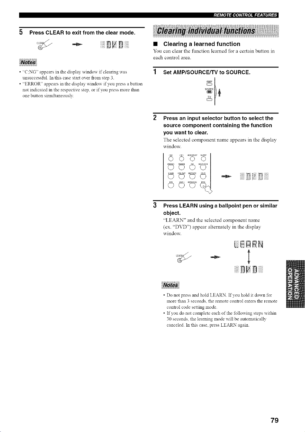
5 Press CLEAR to exit from the clear mode.
c_j __
• "C:NG" appears in the display window if clearing was
unsuccessfnl In this case start over from step 3
• "ERROR" appears in the display window if yon press a button
not indicated in the respective step, or if you press more than
one button simultaneousl3_
• Clearing a learned function
You can clear the function learned for a certain button in
each control area.
Set AMP/SOURCE/TV to SOURCE.
AMP t
Press an input selector button to select the
source component containing the function
you want to clear.
The selected component name appears in the display
window.
°°UT°
© i?i; i
Press LEARN using a ballpoint pen or similar
object.
"LEARN" and the selected component name
(ex. "DVD") appear alternately in the display
window.
_.2" .'2
- l
!? D
• Do not press and hold LEARN If you hold it down i\_r
more than 3 seconds, the remote control enters the remote
control code setting mode
• If yon do not complete each of the following steps within
30 seconds, the learning mode will be automatically
canceled In this case, press LEARN again
79
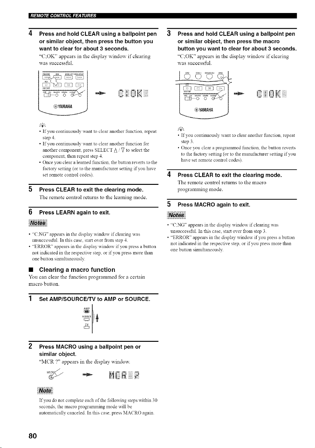
|:/.._j_[O]II[I,[O]_TII:{O]I_._.___|II]:/-'I"
Press and hold CLEAR using a ballpoint pen
or similar object, then press the button you
want to clear for about 3 seconds.
"C;OK" appears in the display window if clearing
was successful.
®YANAHA
J Jil:!
• m, _ _m = ===_= _
• If you continuously want to clear another function, repeat
step 4.
• If you continuously want to clear another function for
another component, press SELECT 5 / V to select the
component, then repeat step 4.
• Once you clear a learned function, the button reverts to the
*"actor3"setting (or to the n'lanut;actnrer setting if you have
set remote control codes).
5 Press CLEAR to exit the clearing mode.
The remote control returns to the learning mode.
6 Press LEARN again to exit.
• "C:NG" appears in the display window if clearing was
_.arsuccessful. In this case. start over from step 4.
• "ERROR" appears in the display window if you press a button
not indicated in the respective step, or if you press more than
one button sin'mltaneously.
• Clearing a macro function
You can clear the function progrannned for a certain
macro button.
Set AMP/SOURCE/TV to AMP or SOURCE.
Press MACRO using a ballpoint pen or
similar object.
"MCR ?" appears in the display window.
Not.,
If you do not complete each of the following steps within 30
seconds, the macro progranmling mode will be
automatically canceled. In this case, press MACRO again.
Press and hold CLEAR using a ballpoint pen
or similar object, then press the macro
button you want to clear for about 3 seconds.
"C;OK" appears in the display window if clearing
was successful.
• If you continuously want to clear another function, repeat
step 3.
• Once yon clear a progrannned function, the button reverts
to the factory setting (or to the manut;acturer setting if you
have set remote control codes).
4 Press CLEAR to exit the clearing mode.
The remote control returns to the macro
programming mode.
5 Press MACRO again to exit.
• "C:NG' appears in the display window if clearing was
unsuccessful. In this case, start over from step 3.
• "ERROR" appears in the display, window if yon press a button
not indicated in the respectix e step, or if you press more than
one button silnultaneously.
80
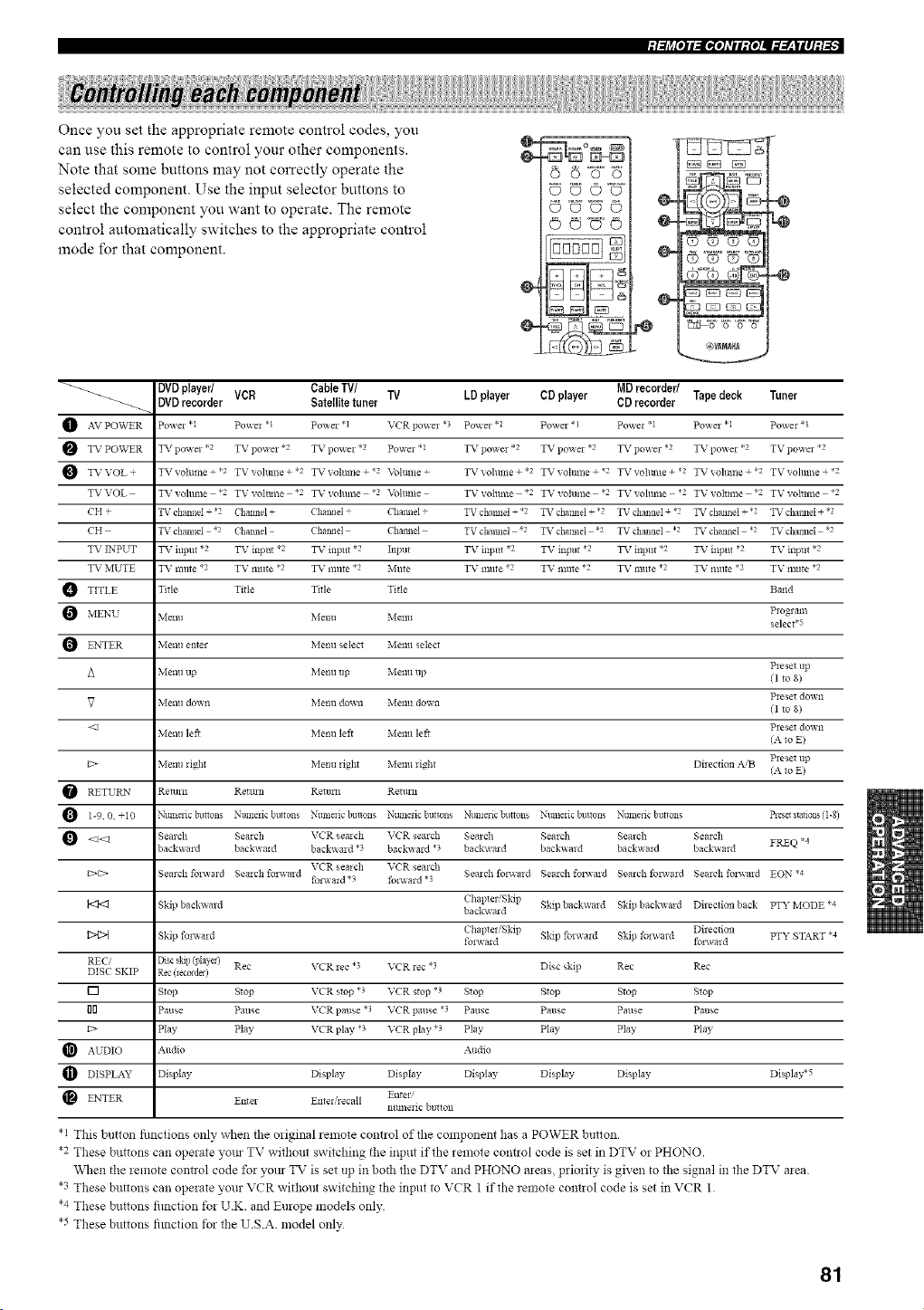
Once you set the appropriate remote control codes, you
can use this remote to control your other components.
Note that some buttons may not correctly operate the
selected component. Use the input selector buttons to
select the component you want to operate. The remote
control automatically switches to the appropriate control
mode for that component.
_U©'U
0©©0
0©_'0
@4
@4
(D (D ¢3 O
o-
e:f_% _ _" '_ W
. (_YIIIIHI
@
-@
_ DVD player/ Cable TV/ MD recorder/ Tape deck Tuner
VCR TV LD player CD player
_ DVD recorder Satelite tuner CD recorder
AV PO\VER Powel *1 Pov_ el * l Po'_ er .1 VCR powel *3 Pov_el *1 Po'_ er *l Powe1.1 Po'_ e1 *1 Po'_ el *l
TV PO_VER TV po_ et *2 TV po_x el *2 TV powei .2 Po_ el *1 TV po_xe1 *2 TV po_x e1.2 TV po_ et *2 TV po_xe1 *2 TV po_xel .2
TV VOL + TV volllme + *2 TV vohlllle + *2 TV _ohllne + ,2 Vohlllle + TV vohlllle + *2 TV _ohllne + ,2 TV vollillle + *2 TV vohllne + *2 TV voltllne + ,2
TVVOL g_vrvohlllle *2 Tgvoltlllle *2 TVvolunle "2 Vohlllle Tgvolllme *2 TVvolunle "2 TVvohlllle *2 Tgvolllnle *2 Tgvolllnle "2
CH + TV channel + *2 Channel + Chaired Chaillel + TV chaillel .2 TV chaimeI + 2 TV channel + *2 TV channel + .2 TV chalmeI + 2
CH TV channel .2 Channel Chaired Chaillel TV chaillel 2 TV chaimeI *2 TV channel .2 TV channel .2 TV chalmeI 2
TV INPUP g_vr iilpllt *2 TV inptlt *2 TV illpilt *2 Illpllt TV i11ptlt *2 TV illput *2 TV iilpllt *2 TV inptlt *2 TV inpllt *2
T_ 7 METpE T_ 7 mute *2 TV IXlllte `2 TXv r Inure *2 Mllte T_ r 1]lllte `2 TXv r Ixltlt e *2 Txv 7 l't]Ilt e _2 T_ r IXlllte `2 T_ r IXlllte *2
TITLE Title Title Title Title Band
Plogram
MENU Menu Menu Menu select.5
ENTER Menu enter Menu select Menu select
Pleset up
Menu up Menu up Menu up (1 to 8)
Pleset do,Ai1
V Menu down Menu down Menu down 11 to 8)
<::1 Pleset do,An
Menu lef* Menu left Menu lek (A to E)
Pleset up
C> Menu light Menu light Menu light Dilection A,B (A to E)
RETUP, zN Retmn Retmn Rettmi Remm
1-9.0, +10 N_mlelic buttons Nmnefic britons Numeric bulons N_mleric buttons Nmnexic buttons Nlmlefic bulons Nmnefic bnlons _ese_ s_a_ions(1-8)
<1<1 Seaich Seaich VCR seaich VCR semch Semch Seaich Sealch Seaich FREQ *4
back_xmd backwald backx_ aid *3 back_x ard .3 backwald backx_aid back_x aid backwmd
VCR seaich VCR semch
_>_> Sealch fol_xald Sealch fo*wmd Seaich fold,,aid Search fol-a-a*d Sealch fol_xald Seaich folv, ald EON *4
foiax aid *3 foi_x ard *?
Chapter'Skip Skip backwmd Skip backwmd DilecIion back PTY MODE *4
Skip backx_ aid backwald
1>4>t Skip fol,a,ald fblx_aldChapter'Skip Skip forwaid Skip foia_,al d Directionfol_ard PTY START *4
REC, Disc skill(Illayel)
DISC SKIP Rec(_ec0_de*) Rec VCR rec *? VCR rec *3 Disc skip Rec Rec
[] Stop S*op VCR stop *3 VCR stop *t S*op Stop Stop Stop
i]rl Pause Pause VCR pause *t VCR pause *3 Pause Pause Pause Pause
C> Play Pay VCR play *3 VCR play *3 Pay Play Play Play
AUDIO Aildio Audio
DISPLAY D sI ay Display Display D _p ay Display Display Display .5
ENTER Enter Ente_ lecall Enter/
11tllnekic bltton
*1 This bulon fimctions only when the original remote control of the component has a POWER button.
*2 These buttons can operaIe yore TV without switching the input if the remote conlol code is set in DTV or PHONO.
When the remote control code for yore TV is set up in both the DTV and PHONO areas, priority is given to file signal in the DTV area
*3 These buttons can operate your VCR without switching tile input to VCR 1 if the remote cont!ol code is set in VCR 1.
*4 These buttons fimction t)r U.K. and Europe models only.
*5 These buttons fimcfion t)r fl_e U.S.A. model only
81
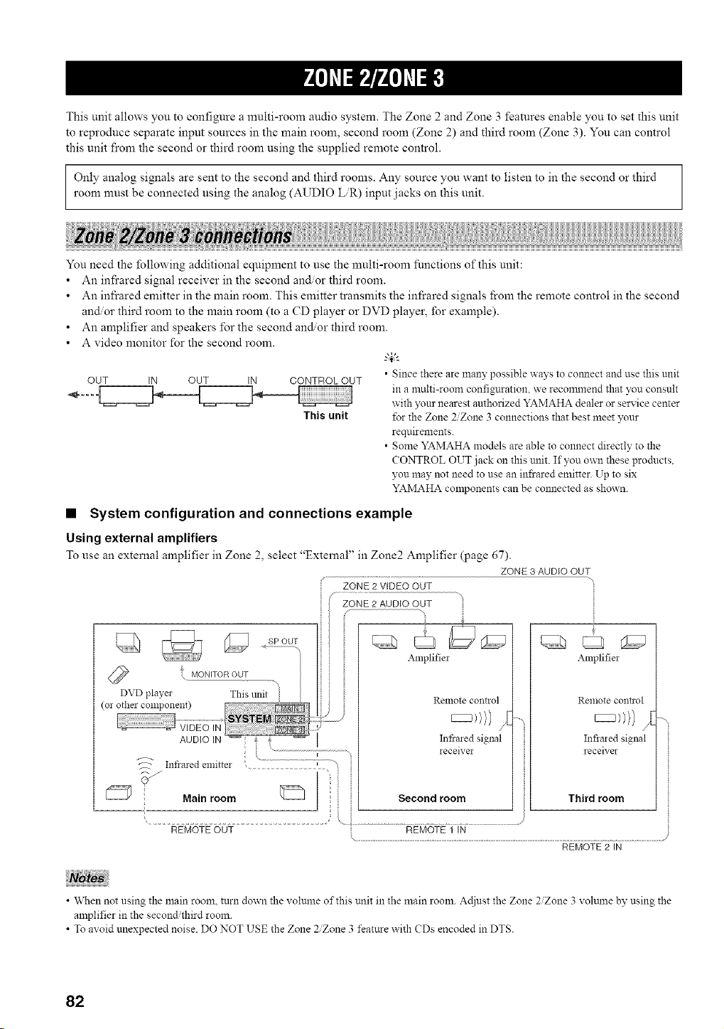
This unit allows you to configure a multi-room audio system. The Zone 2 and Zone 3 features enable you to set this unit
to reproduce separate input sources in the main room, second room (Zone 2) and third room (Zone 3). You can control
this unit fi'om the second or third room using the supplied remote control.
Only analog signals are sent to the second and third rooms. Any source you want to listen to in the second or third
room nmst be connected using the analog (AUDIO LR) input jacks on this unit.
You need the following additional equipment to use the multi-room limetions of this unit:
• An infi'ared signal receiver in the second and/or third room.
• An infrared emitter in the main room. This emitter transmits the infrared signals from the remote control in the second
and/or third room to the main room (to a CD player or DVD player, for example).
• An amplifier and speakers for the second and/or third room.
• A video monitor for the second room.
CONTROL OUT
This unit
OUT IN OUT IN
• Since there are many possible ways to connect and use this unit
in a multi-room configuration, we reconnnend that you consult
with )x_ur nearest authorized YAMAHA dealer or service center
for the Zone 2/Zone 3 connections that best meet your
requirements.
• Some YAMAHA models are able to connect directly to the
CONTROL OUT jack on this unit. If you own these products,
you may nut need to use an infrared emitter. Up to six
YAMAHA components can be connected as shown.
• System configuration and connections example
Using external amplifiers
To use an external amplifier in Zone 2, select "External" in Zone2 Amplifier (page 67).
ZONE 3 AUDIO OUT
ZONE 2 VIDEO OUT
MONITOR OUT
SP OUT
ZONE 2 AUDIO OUT
Infrmed emitter , .........................
Main room
i
REMOTEOUT
Amplifiei
Remote contiol
Infrared signal
ieceivei
Second room
Amplifiei
Remote co!ltlol
Infimed signal
receiver
Third room
• "_Nen not using the main room, turn down the volume of this unit in the main room. Adiust the Zone 2Zone 3 xohune by using the
amplifier in the second third room.
• To avoid unexpected noise, DO NOT USE the Zone 2Zone 3 feature with CDs encoded in DTS.
82
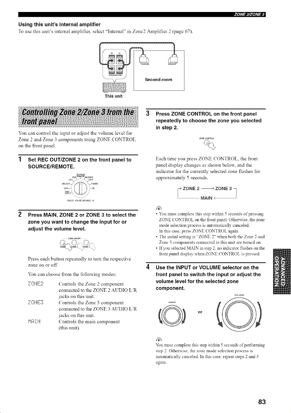
Using this unit's internal amplifier
• ' _ .... _, 7," -_ "_
To use this umt s internal amphiler, select Internal m Zone_ Amphher 2 (page 67).
This unit
Second room
You can control the input or adjust the volume level for
Zone 2 and Zone 3 components using ZONE CONTROL
on the front panel•
1 Set REC OUT/ZONE 2 on the front panel to
SOURCE/REMOTE.
Press MAIN, ZONE 2 or ZONE 3 to select the
zone you want to change the input for or
adjust the volume level.
g
Press each button repeatedly to turn the respective
zone on or off.
You can choose from the following modes:
;i!:.=.I_Ii".ii!!!12 Controls the Zone 2 component
connected to the ZONE 2 AUDIO LR
jacks on this unit.
;i!:.=.()i".ii!!!i:i!; Controls the Zone 3 component
connected to the ZONE 3 AUDIO LR
jacks on this unit.
,i"_""_,....,.,.T_"i., Controls the main component
(this unit).
Press ZONE CONTROL on the front panel
repeatedly to choose the zone you selected
in step 2.
Each time you press ZONE CONTROL, the front
panel display changes as shown belm_\ and the
indicator for the currently selected zone flashes for
approximately 5 seconds•
• You must complete this step within 5 seconds of pressing
ZONE CONTROL on the front panel. Otherwise, the zone
mode selection process is amomatically canceled
In this case, press ZONE (ONTROL again.
• The initial setting is "ZONE 2" when both the Zone 2 and
Zone 3 components connected to this trait are turned on.
• If you selected MAIN in step 2, no indicator flashes on the
front panel display when ZONE CONTROL is pressed
Use the INPUT or VOLUME selector on the
front panel to switch the input or adjust the
volume level for the selected zone
component.
VOLUME
_NPUT !_l
or
You mnst complete this step within 5 seconds ofperfnrming
step 2. Otherwise, the zone mode selection process is
automatically canceled. In this case. repeat steps 2 and 3
again
83
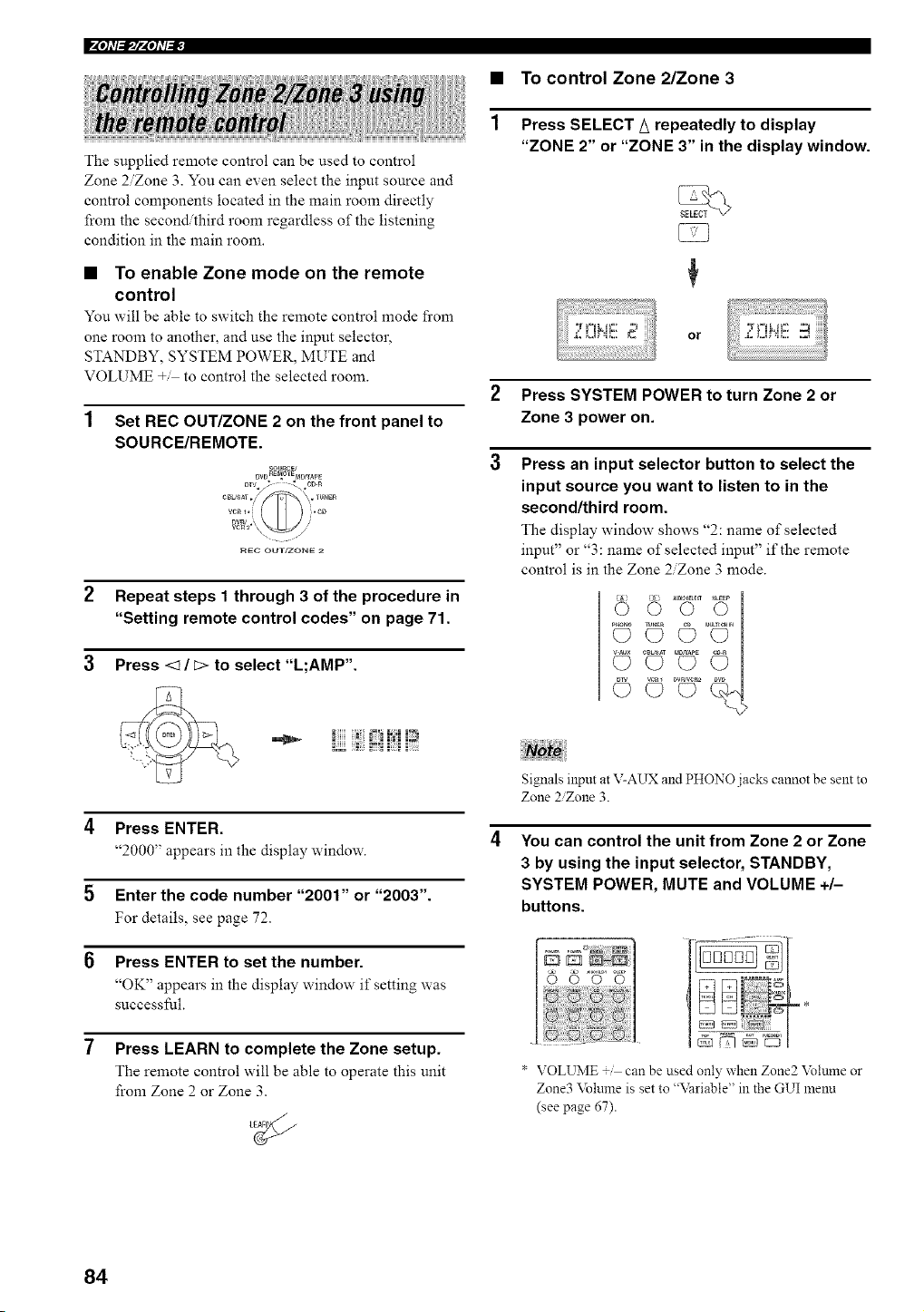
F4OhT_lF4OhT_
The supplied remote control can be used to control
Zone 2/Zone 3. You can even select the input source and
control components located in the main room directly
from the second/third room regardless of the listening
condition in the main room.
• To enable Zone mode on the remote
control
You will be able to switch the remote control mode from
one room to another, and use the mput selector,
STANDBY, SYSTEM POWER, MUTE and
VOLUME +/ to control the selected room.
Set REC OUT/ZONE 2 on the front panel to
SOURCE/REMOTE.
DVD_OTEpaDrrA_E
Dun .,, ,'
vcR2 \
r_EC OUT/ZONE
2 Repeat steps 1 through 3 of the procedure in
"Setting remote control codes" on page 71.
3 Press <1/_> to select .....L,AMP .
!iiiiiii
4 Press ENTER.
"2000" appears in the display window.
5 Enter the code number "2001" or "2003".
For details, see page 72.
Press ENTER to set the number.
"OK" appears in the display window if setting was
successihl.
7 Press LEARN to complete the Zone setup.
The remote control will be able to operate this unit
from Zone 2 or Zone 3.
1
To control Zone 2/Zone 3
Press SELECT _ repeatedly to display
"ZONE 2" or "ZONE 3" in the display window.
or 2 ,]!'i!!!
2 Press SYSTEM POWER to turn Zone 2 or
Zone 3 power on.
3 Press an input selector button to select the
input source you want to listen to in the
second/third room.
The display window shows "2: name of selected
input" or "3: name of selected input" if the remote
control is in the Zone 2/Zone 3 mode.
Signals input at V-AUX and PHONO jacks cannot be sent to
Zone 2Zone 3.
You can control the unit from Zone 2 or Zone
3 by using the input selector, STANDBY,
SYSTEM POWER, MUTE and VOLUME +/-
buttons.
* VOLUME + can be used only' when Zone2 \blume or
T
Zone3 \blume is set to "\_ariable" in the GUI lnenu
(see page 67).
84
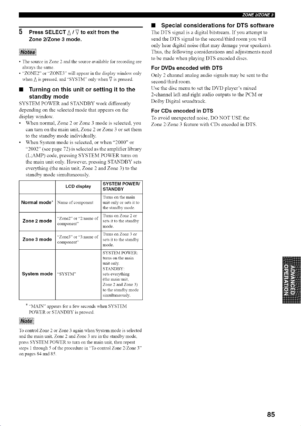
5 Press SELECT A / V to exit from the
Zone 2/Zone 3 mode.
• The source in Zone 2 and the soarce available for recording are
ahvays the same.
• "ZONE2" or "ZONE3" will appear in the display window only
when A is pressed, and "SYSTM" only when V is pressed.
• Turning on this unit or setting it to the
standby mode
SYSTEM POWER and STANDBY work differently
depending on the selected mode that appears on the
display window.
• When normal, Zone 2 or Zone 3 mode is selected, you
can turn on the main unit, Zone 2 or Zone 3 or set them
to the standby mode individually.
• When System mode is selected, or when "2000" or
"2002" (see page 72) is selected as the amplifier library
(L;AMP) code, pressing SYSTEM POWER turns on
the main unit only. However, pressing STANDBY sets
everything (the main unit, Zone 2 and Zone 3) to the
standby mode sinmltaneously.
LCD display
Normal mode* Name of component
"Zone2" or "2:name of
Zone 2 mode
conlponent'
"Zone3" or "3:name of
Zone 3 mode
component'
System mode "SYSTM"
SYSTEM POWER/
STANDBY
Turns on the lnain
unit only o! sets it to
the standby mode
Turns on Zone 2 or
sets it to the standby
mode.
Turns on Zone 3 or
sets it to the standby
mode.
SYSTEM POWER:
tlll!lS on the main
unit only
STANDBY:
sets evelything
(the main mfit,
Zone 2 and Zone 3)
to the standby mode
sinmltaneously.
* "MAIN" appears for a few seconds when SYSTEM
PO\,XTR or STANDBY is pressed.
To control Zone 2 or Zone 3 again when System mode is selected
and the main trait, Zone 2 and Zone 3 are in the standby mode,
press SYSTEM POWER to turn on the main unit, then repeat
steps 1 through 5 of the procedure in "To control Zone 2/Zone 3"
on pages 84 and 85.
• Special considerations for DTS software
The DTS signal is a digital bitstream. If you attempt to
send the DTS signal to the second/third room you will
only hear digital noise (that may damage your speakers).
Thus, the following considerations and adjustments need
to be made when playing DTS encoded discs.
For DVDs encoded with DTS
Only 2 channel analog audio signals may be sent to the
second/third room.
Use the disc menu to set the DVD player's mixed
2-channel left and right audio outputs to the PCM or
Dolby Digital soundtrack.
For CDs encoded in DTS
To avoid unexpected noise, DO NOT USE the
Zone 2/Zone 3 feature with CDs encoded in DTS.
85
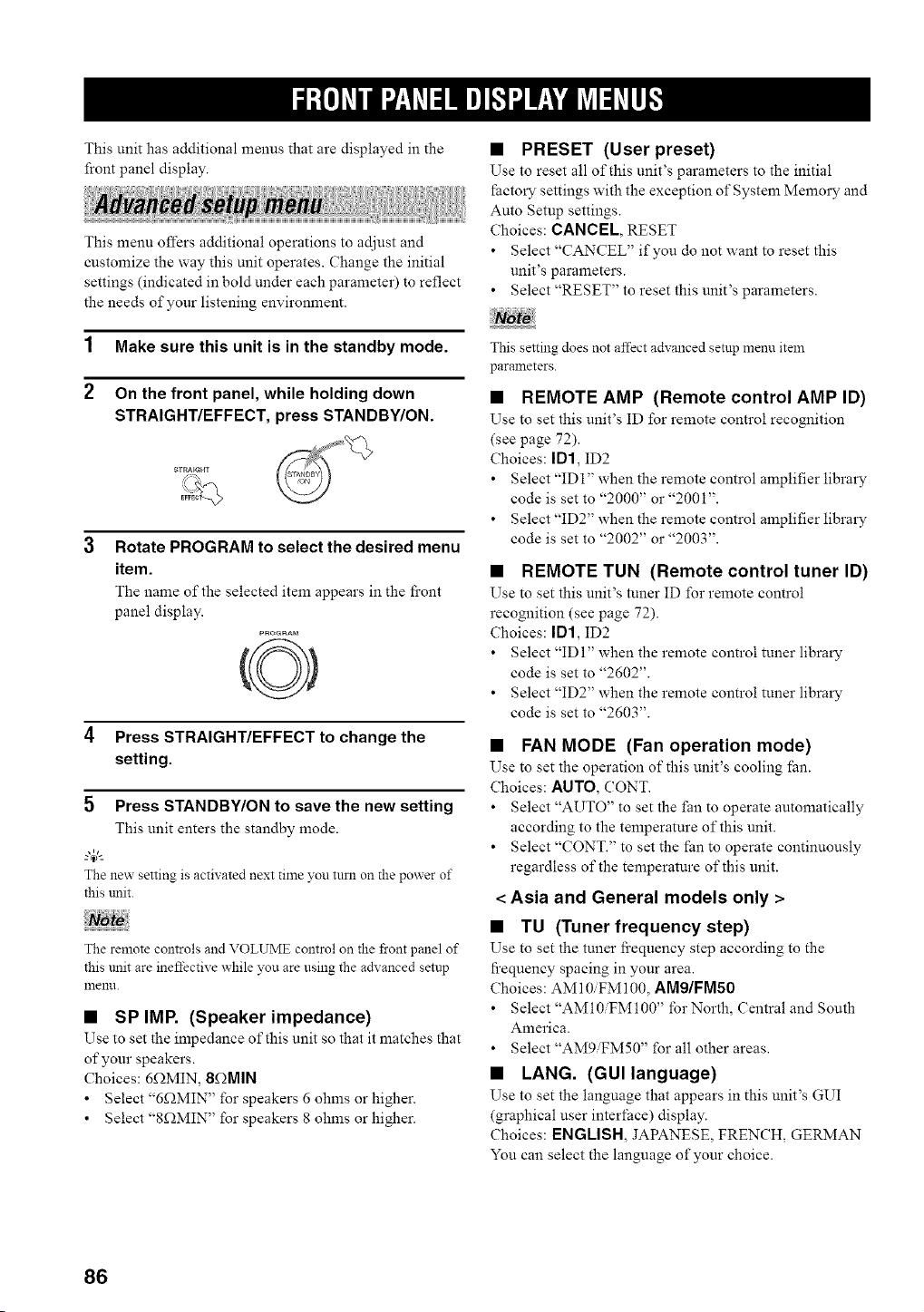
This unit has additional menus that are displayed in the
front panel display.
This menu offers additional operations to adjust and
customize the way this unit operates. Change the initial
settings (indicated in bold under each parameter) to reflect
the needs of your listening environment.
1 Make sure this unit is in the standby mode.
2 On the front panel, while holding down
STRAIGHT/EFFECT, press STANDBY/ON.
STRAIGHT
Rotate PROGRAM to select the desired menu
item.
The name of the selected item appears in the front
panel display.
PROGNAM
4 Press STRAIGHT/EFFECT to change the
setting.
5 Press STANDBY/ON to save the new setting
This unit enters the standby mode.
--'4_'--
The new setting is activated next time you turn on the power of
this unit.
The remote controls and VOLUME control on the front panel of
this unit are ineffective while you are using the adxanced setup
nlenn.
• SP IMP. (Speaker impedance)
Use to set the impedance of this unit so that it matches that
of your speakers.
Choices: 6f2MIN, 8f_MIN
• Select "6f2MIN" for speakers 6 ohms or higher.
• Select "8f2MIN" for speakers 8 ohms or higher.
• PRESET (User preset)
Use to reset all of this unit's parameters to the initial
Pactory settings with the exception of System Memory and
Auto Setup settings.
Choices: CANCEL, RESET
• Select "CANCEL" if you do not want to reset this
unit's parameters.
• Select "RESET" to reset this unit's parameters.
This setting does not affect advanced setup menu item
parameters.
• REMOTE AMP (Remote control AMP ID)
Use to set this unit's ID for remote control recognition
(see page 72).
Choices: ID1, ID2
• Select "ID 1" when the remote control amplifier library
code is set to "2000" or "2001".
• Select "ID2" when the remote control amplifier library
code is set to "2002" or "2003".
• REMOTE TUN (Remote control tuner ID)
Use to set this unit's tuner ID for remote control
recognition (see page 72).
Choices: ID1, ID2
• Select "IDI" when the remote control tuner library
code is set to "2602".
• Select "ID2" when the remote control tuner library
code is set to "2603".
• FAN MODE (Fan operation mode)
Use to set the operation of this unit's cooling fan.
Choices: AUTO, (7ONT.
• Select "AUTO" to set the fan to operate automatically
according to the temperature of this unit.
• Select "CONT." to set the Pan to operate continuously
regardless of the temperature of this unit.
< Asia and General models only >
• TU (Tuner frequency step)
Use to set the tuner fi'equency step according to the
fi'equency spacing in your area.
Choices: AM10iFM100, AM9/FMSO
• Select "AMI0iFM100" lbr North, Central and South
America.
• Select "AMgiFM50" for all other areas.
• LANG. (GUI language)
Use to set the language that appears in this unit's GUI
(graphical user interface) display.
Choices: ENGLISH, JAPANESE, FRENCH, GERMAN
You can select the language of your choice.
86
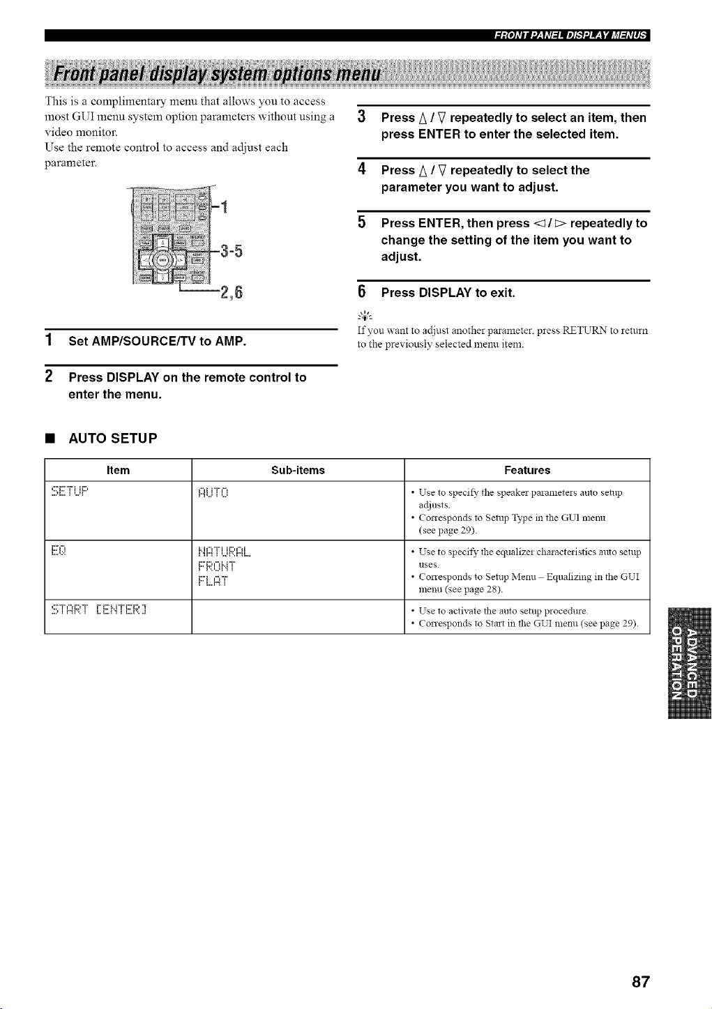
This is a complimentary menu that allows you to access
most GUI menu system option parameters without using a
video monitor.
Use the remote control to access and ac[iust each
parameter.
1 Set AMP/SOURCE/TV to AMP.
2 Press DISPLAY on the remote control to
enter the menu.
3 Press A / V repeatedly to select an item, then
press ENTER to enter the selected item.
4 Press A / V repeatedly to select the
parameter you want to adjust.
5 Press ENTER, then press <1/c> repeatedly to
change the setting of the item you want to
adjust.
6 Press DISPLAY to exit.
If you x_antto adjust another parameter,press RETURN to return
to the pre_iously selected menu item.
• AUTO SETUP
Item Sub-items Features
....,::ri:::'"H,_...._ ,...,_ii:::' r"i,...,_"_i i"i__'5_,..., • Use to specif}' tile speakel paiameteis auto setnp
adjusts.
• Conesponds to Setup Type in the GUI menu
(see page 29).
_....,.:.:i:r_", _'_"_i"i_","r_,...,_'..m_ii_::,,"_i.... • UTse to specit}"tile equalizei chalacteristicsautosetup
i:::'i ,"*_"r • Conesponds to Setup Menu Equalizing in the GUI
i i,,,, r'_ _
menu (see page 28).
,::r°i","*_i:::,°i" i=i:::'i..i"ri:::'_:::,"i • Use to activate the auto setup procedure
• Conesponds to Start in the GUI menu (see page 29).
87
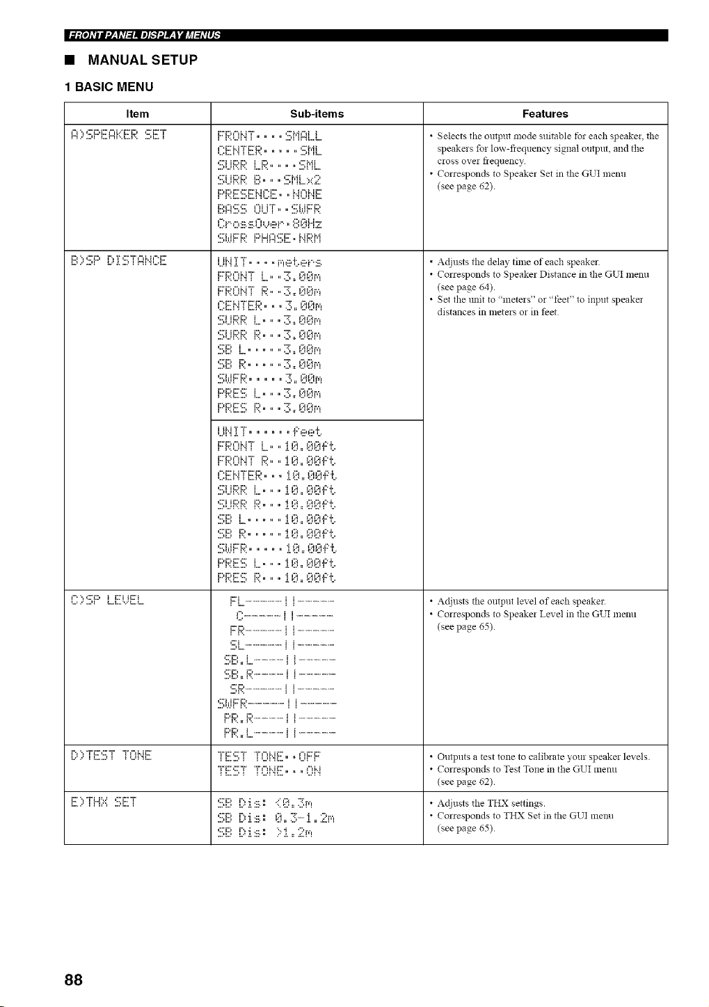
• MANUAL SETUP
1 BASIC MENU
Item Sub-items Features
¢.._.., ,:::'i:::_;::'_"d..='i:::_i:::, ,::;=i:::_"i"
i==", ,:::'E) i i:::_ii_;::'i
,,,.=,,' .,,,,l _,,,l,,,=',.."_,,,_....
i2:_i:::,_"d..i "i" _:::'i'._¢"_i i
_i iiiii_L_ ill) _ _ _;=i_i ._i_
Oi..c,:ii_,:ii_,O=,.,,ii_i..,,?,_;!iiiz
F::i;I:ONTL,, ,,3.00i','_
,,,.I,,,,H _ L,A', " .............
....'_,,,'_',,l ".. I,,,, " .............
....,=,,,,i m " " " " .............
i i',,I,,,,,,,,, i, H . .............
i l',,l,,,,,,,J i,, . .............
i,,.ii',,ii "[,............I::",ii_et,
L*I,,,,H I L,,A', ,L,:J _:,,,_:,,,F ,,,
,,,, i ,i 1,,,i,,j "1 i,i i ,,ii ,,i ,L"*1,
i;:'i ......................... i i .........................
_" ......................... ii .........................
I I',= I I
'::[=i.i i:::'i::) .........................i i .........................
i:::'i::) i .................... i i .........................
I I',,=_I .... I I
• Selects the output mode suitable tbr each speaker, the
speakers for low-fiequency signal output, and the
cross over fiequency
• Corresponds to Speaker Set in the GUI menu
(see page 62).
• Adjusts the delay time of each speaker.
• Corresponds to Speaker Distance in the GUI menu
(see page 64).
• Set the trait to "meters" or "feet" to input speake_
distances in meters or in feet
• Adjusts the output level of each speaker.
• Corresponds to Speake_ Level in the GUI menu
(see page 65).
l.r"i%."""r' i_r_:::'"i"ii....-., i "1"i"i Mi_:'__...,_ 'ii. "1__1::'_:::'"i"__......., _ "i" i"lMi:::'l,..._1 'ii.... " " _...,_I"i i:::'i::'_i • O'dtplltS a test tone to calibrate your speaker levels.
"i"_:::',:::'"i" "i"¢"_Mi:::', ..... _"d..i • Correspo!]ds to Test Tone in the GUI menll
(see page 62).
_:r'.,"r'u,..., ,:::_:r°r' ,:::_::,i".,.; ...... ::'I::_.. i'%', • Adjusts the THX settings.
,2:'_:::,i"._.; _..• I:::I.. i':_-...,i .r ';:'r,', • Corresponds to THX Set in the GUI menu
,::_::, i".,.; ¢.... '....i .. ";:'r,', (see pa_e 65).
88
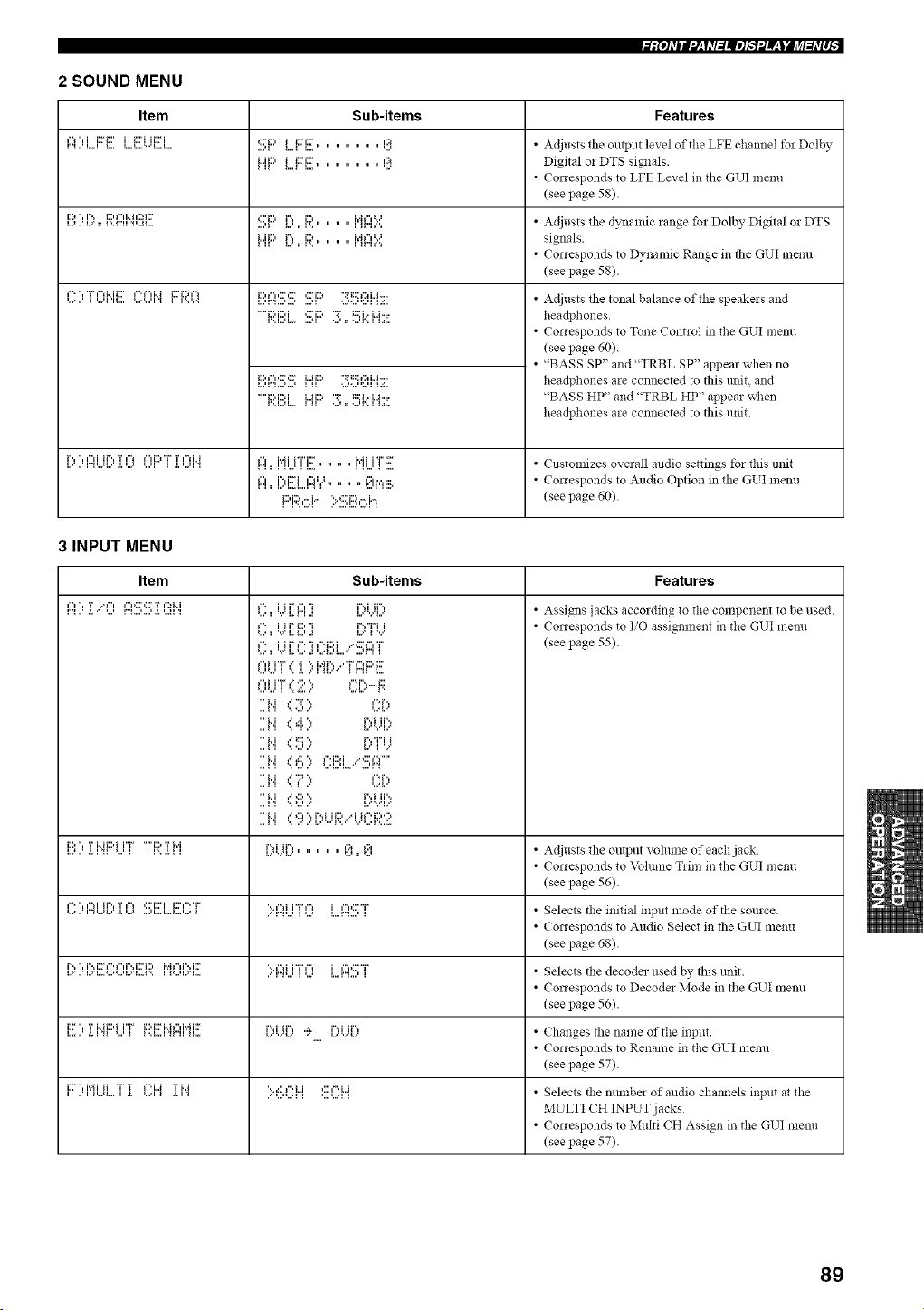
2 SOUND MENU
Item Sub-items Features
r'4..'L,A L.. L,A...._..'L,A. ....'_ I...._ i... " " " " " ':J
.. ........... .... :: ...... .:..
.. ....... ...+ :: <.... <i.
• Adjusts the output level of the LFE channel for Dolby
Digital or DTS sim]als
• Corresponds to LFE Le;;el in the GUI memt
(see page 58)
• Adjusts the dynamic range for Dolby Digital or DTS
signals
• Corresponds to Dynamic Range in the GUI metal
(see page 58)
• Adjusts the tonal balance of the speakers and
headphones
• Corresponds to Tone Control in the GUI menu
(see page 60).
• "BASS SP" and "TRBL SP" appear when no
headphones are connected to this trait, and
"BASS HP" and "TRBL HP" appear when
headphones are connected to this unit
r'., ".,¢"li it'., T i-i i"d:::+"i" T ¢"iM i"l Mi i"r'i:::" Mi i"i"ixr • Customizes overall audio settings for this tlllit.
T
,", i"d::ri,",'.++ ,, l:::Ir,',.:::+ • Corresponds to Audio Option in the GUI men!l
I:::'F;;:,::;I+ ;::!!!;i!!',,::;i++ (seepage60)
3 INPUT MENU
Item Sub-items Features
i::,", Ti..+i::)i i"L" "i"i:::,TM
L++..' ._+1_I _..., _ I I'.< ._+I I
i"+i ir'., 1'[:+ +31
L<.<I... . ,, . ,:.++ +:..,
'..<,"+i i"r',"+ i ,"+,:::'"i"
• Assigns jacks according to the component to be used
• Corresponds to I/O assim]ment in the GUI menu
(see page 55)
• Adjusts the output volmne of each jack
• Corresponds to Volume T*im in the GUI menu
(see page 56)
• Selects the initial input mode of the source
• Corresponds to Audio Select in the GUI menu
(see page 68)
• Selects the decoder used by this trait
• Corresponds to Decodes Mode in the GUI menu
(see page 56)
• Changes the name of the input
• Corresponds to Rename in the GUI menu
(see page 57)
• Selects the munbez of audio cham]els input at the
MULTI CH INPUT jacks
• Corresponds to Multi CH Assim] in the GUI nlenu
(see page 57)
89
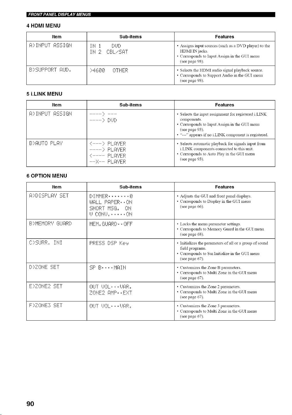
II:l:£o]_,llll'J__f_,l:lllel_'3f__t'JJ¢l:hq#_
4 HDMI MENU
Item Sub-items Features
i'l ", T i..iii::,i i"i" I"i,:::',::F T I':::H T M '1 i%i Jr, • Assigns input sources (SllCh as a DVD player) to tile
rii 2 ,-.i:::,i ...,:::,,r HDMIINjacks
.[. 1 'i =..=l...q..,.. ,...=i...i i
• Corresponds to Input Assign in tile GUI menu
(see page 98)
i:::,,,:::i i_::,i:::,,-,i:::,'r,',i ir, ,.i ,:::,:_,:_ ,", ri.ii:::i:::, • Selects tile HDMI audio signal playback SOllrce
L.2 ,.' ,...n..21 1 =..2F,, I r'_=..21...' :: .., ,.Tt..n:.2=:.2 =..2 I I II....F,,
• Corresponds to Support Audio in tile GUI menu
(see page 98)
5 i.LINK MENU
Item Sub-items Features
¢"_", TMK:,i i"i" _"K:',:F'r_'::M
,-,. ,, ",, _., _ r",..,.., _._,, ", ....................:::................. Selects tile input assignment fo: registe:ed iLINK
.................... % i%i ir'., conlpo!lents.
... L.......I...
• Corresponds to Input Assign in tile GUI menu
(see page 93)
• "---" appears if no i LINK component is registered
,.., r",,..,,,.,i::'",,",i i'r ,", ,i::'i,,,_"°" .=..................." ,i:::'i,..,-,=,..,,"0 .;i::r_::, • Selects automatic playback tbr signals illptlt fioln
...................., i:::,i,",, .;i:::'i:::, iLINK components connected to this llllit
:::....................,i:::'i,..,-,_ ,..,,",, .;i:ri:::, • Corresponds to Auto Play. in tile GUI menll
..........==.......... i:::,i,"0.,i:r_::, (seepage 93)
6 OPTION MENU
Item Sub-items Features
¢"1", r'., T Ci:::,i ¢"li.j ,::Fi::F"i" i% T Mh'ii::Fi:::, ,, "::' • Adjusts tile GUI and fiont panel displays
i.=.ii::IL.i...F:'I::'4i:::'i!!:F;::0H • Corresponds to Display in tile GUI menu
,::'i...iF'd:)"i" i',=i,:::'l'::: ¢"d..i (see page 66).
i i I"'l"li..ii i , ,, {"li..i
'v" '...='...'FFv':: " " " =...'H
i:) ", i','ii:_i','il"li::'i.. I {':::i h"{i:::'i =`, i'¢iK::'i','i I':.':i il"li:::'i", I"lK::'i:::' • Locks file nlenu parameter settillgs.
• Corresponds to Memory Gua:d in tile GUI menu
(see page 68)
,-=, ,:::ii_::,i:::, Ti i T i:::';;:'i:::'::_'::_ ['Y::::i:::'K,:::,'.i • h:ifializes tile parameters of all o: a group of sound
field programs
• Corresponds to Sur Initialize in tile GUI menu
(see page 67)
i".,,::_,-,i ii::: ,::_i:::"T ,:::_i:::,i:::,, i,i ,', r i i B pi.r"."::...'...'_'H.... ....'_...i ....,_ i...' " " " _ U".'._.H • Customizes tile Nolle a:ameters
• Corresponds to Multi Zone in tile GUI menu
(see page 67)
i:r, ::q-,i ii::: :_ <::_::r ,",i i"r i i,,i i i, ,1:::, 2 p
i.....'::...,...,H_.....::. -..'_.... _ ,..._..., _ ".'_...,_.... " " 'v'r"w.. :: • Custonlizes theZone arameters
°:::,,Mill:":_ ,",i,ii:::, i:::=: i" • Corresponds to Multi Zone i!l tile GUI illenu
(see page 67)
i:F'.,"::q-:Mi:::'":r*:::'i:::'"i" _-:i i"r' i i_"H i i_"_i:::, • Customizes tile Nolle 3 parameters
• Corresponds to Multi Zone in tile GUI menu
(see page 67)
90
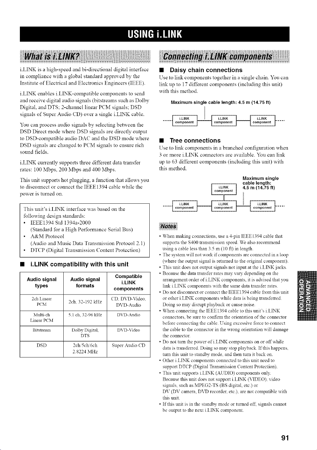
i.LINK is a high-speed and bi-directional digital inter_ace
in compliance with a global standard approved by the
Institute of Electrical and Electronics Engineers (IEEE).
i.LINK enables i.LINK-compatible components to send
and receive digital audio signals (bitsn'eams such as Dolby
Digital, and DTS; 2-channel linear PCM signals; DSD
signals of Super Audio CD) over a single i.LINK cable.
You can process audio signals by selecting between the
DSD Direct mode where DSD signals are directly output
to DSD-compatible audio DAC and the DSD mode where
DSD signals are changed to PCM signals to ensure rich
sound fields.
i.LINK currently supports three different data transfer
rates: 100 Mbps, 200 Mbps and 400 Mbps.
This unit supports hot plugging, a function that allows you
to disconnect or connect the IEEE1394 cable while the
power is turned on.
This unit's i.LINK interface was based on the
following design standards:
• IEEE1394 Std 1394a-2000
(Standard for a High Performance Serial Bus)
• A&M Protocol
(Audio and Music Data Transmission Protocol 2.1)
• DTCP (Digital Transmission Content Protection)
• i.LINK compatibility with this unit
Audio signal Audio signal Compatible
i.LINK
types formats
components
2ch Lmem CD DVD-Video.
PCM 2ch. 32-192 kHz DVD-Audio
Multi-ch 5.1 ch. 32-96 kHz DVD-Audio
Linear PCIM
Bitstream Dolby Digital, DVD-Video
DTS
DSD 2ch 5ch 6ch Super Audio CD
2.8224 MHz
• Daisy chain connections
Use to link components together in a single chain. You can
link up to 17 different components (including this unit)
with this method.
Maximum single cable length: 4.5 m (14.75 ft)
• Tree connections
Use to link components in a branched configuration when
3 or more iiINK connectors are available. You can link
up to 63 different components (including this unit) with
this method.
Maximum single
cable length:
4.5 m (14.75 ft)
• When making connections, use a 4-pin IEEEI394 cable that
supports the $400 transmission speed. We also recomlnend
using a cable less than 3.5 na (10 ft) in length.
• The systeln will not work if components are cmmected in a loop
(where the output signal is returned to the original component).
• This unit does not output signals not input at the i.LINK jacks.
• Because the data transfer rates lnay xa D" depending on the
arrangement order of iiINK components, it is advised that you
link i.LINK components with the same data transfer rates.
• Do not disconnect or connect the IEEE1394 cable i_om this unit
or other i.LINK components while data is being transferred.
Doing so may disrupt playback or cause noise.
• When connecting the IEEE1394 cable to this unit's i.LINK
cmmectors, be sure to confirm the orientation of the connector
before connecting the cable. Using excessix e force to connect
the cable to the connector in the wrong orientation will damage
the connector.
• Do not turn the pm_er ofiiINK components on or offwhile
data is transferred. Doing so may stop playback. If this happens,
turn this unit to standby mode, and then ttun it back on.
• Other i.LINK components connected to this unit need to
support DTCP (Digital Transmission Content Protection).
• This trait supports i.LINK (AUDIO) components only.
Because this unit does not support i.LINK (VIDEO), video
signals, such as MPEG2-TS (BS digital, etc.) or
DV (DV camera, DVD recorder, etc.), are not compatible with
this unit.
• If this unit is in the standby mode or turned ot'12signals camlot
be output to the next i.LINK component.
91
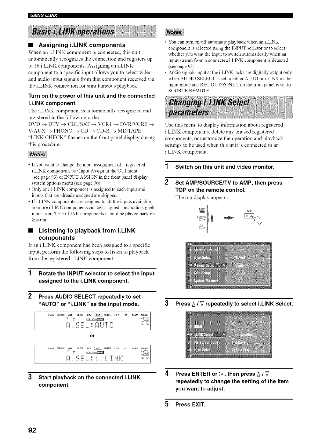
I_.VflT,l_,(h'l"
• Assigning i.LINK components
When an iiINK component is connected, this unit
automatically recognizes the connection and registers up
to 16 i.LINK components. Assigning an iiINK
component to a specific input allows you to select video
and audio input signals from that component received via
the iiINK connection for simultaneous playback.
Turn on the power of this unit and the connected
i.LINK component.
The i.LINK component is automatically recognized and
registered in the following order:
DVD _'. DTV > CBLiSAT _'. VCR1 _'. DVR.VCR2 _'.
V-AUX _ PHONO ,* CD ,* CD-R _ MDiTAPE
"LINK CHECK" flashes on the front panel display during
this procedure.
• If you want to change the input assignment of a registered
i.LINK component, use Input Assign in the GUI menu
(see page 93) or INPUT ASSIGN in the front panel display
system options menu (see page 90).
• Only one i.LINK component is assigned to each input and
inpms that are alrea@ assigned are skipped.
• If i.LINK components are assigned to all the inputs available,
no more i.LINK components can be assigned, and audio signals
inpm frOln these i.LINK components cannot be played back on
this unit.
• Listening to playback from i.LINK
components
If an iiINK component has been assigned to a specific
input, perform the following steps to listen to playback
from the registered i.LINK component.
1 Rotate the INPUT selector to select the input
assigned to the i.LINK component.
2 Press AUDIO SELECT repeatedly to set
"AUTO" or "i.LINK" as the input mode.
wL_x _'J_;qeR_w_l c_ Dw _ m_APE CD_ C_ TU_E_ P,ONO
,, }0 _ _c/I,_,
m
_"_ C' C: } ,, _"_i i'T' _"_ 2_ /
or
_"_ C'i7} ,, ; i Tgib"
i"_ _ .,.d L.. L.. =_ d. = L.. d. i '_ _',.
3 Start playback on the connected i.LINK
component.
• You can turn onioffautomatic playback when an i.LINK
component is selected using the INPUT selector or to select
whether you want the input to switch automatically when an
input stream from a connected i.LINK component is detected
(see page 93).
• Audio signals input at the i.LINK jacks are digitally output only
when AUDIO SELECT is set to either AUTO or i.LINK as the
input mode and REC OUT/ZONE 2 on the front panel is set to
SOURCE REMOTE.
Use this menu to display information about registered
iiINK components, delete any unused registered
components, or customize the operation and playback
settings to be used when this unit is connected to an
iiINK component.
1 Switch on this unit and video monitor.
2 Set AMP/SOURCE/TV to AMP, then press
TOP on the remote control.
The top display appears.
3 Press _ / V repeatedly to select i.LINK Select.
4 Press ENTER or c>, then press A /
repeatedly to change the setting of the item
you want to adjust.
5 Press EXIT.
92
• Information (Information)
Use this feature to display the following information:
operation status of registered i.LINK components,
registered i.LINK components that have been deleted, and
iiINK signals that are currently being received.
i.LINK Select > Information >
Choices: Details, Delete, Protect, i.LINK Status
Select Details to display the lbllowing information
about the selected i.LINK component.
Vendor: Displays the name of the manufacturer for
your iiINK component.
Model: Displays the model name of your i.LINK
component.
Active (connected) or Non Active (not
connected): Displays depending on whether your
iiINK component is connected.
Audio (for audio signals) or Non Audio (for non-
andio signals): Displays depending on whether your
iiINK component supports audio signal playback.
Assign: Displays the name of the input assigned to
the selected i.LINK component.
Select Delete to delete the selected i.LINK component
from the registered components list. To delete, press
ENTER. You can only delete non-active and
unprotected i.LINK components.
Select Protect to protect the selected iiINK
component from being accidentally deleted.
Select i.LINK Status to display operation status of
i.LINK signals that are currently being received. You
can also use this feature to delete all non-active and
unprotected i.LINK components together at once.
Information about unregistered i.LINK components is not
available in the GUI menu. These i.LINK components cannot be
used on this unit although they can be output to other i.LINK
colrlponents.
• Select (Input select)
Use this feature to select which registered i.LINK
component's audio signal will be selected for playback.
i.LLVK Select > Select >
Select the name of the desired component and press
ENTER to switch the input. When you select the desired
component, its manufacturer and model information
appear along with its input assignment.
'_"lh'{'lNeh'll
• Input Assign (Input assign)
Use this feature if you want to change the input
assignment of a registered i.LINK component. You can
select to assign the i.LINK component to any of the
various inputs (PHONO to V-AUX).
i.LINK Select > I,put Assign >
Choices: PHONO, CD, CD-R, MDiTAPE, DVD, DTV,
CBLiSAT, VCR 1, DVR VCR 2, V-AUX,
No Assignment
1 Press A / V repeatedly to select the i.LINK
component you want to assign, then press
[>.
2 Press/_ / V repeatedly to select the input for
the i.LINK component, then press ENTER.
This menu item is also available in the front panel display system
options menu (see page 90).
• Auto Play (Auto Play)
Use this feature to turn onoff automatic playback when an
i.LINK component is selected using the INPUT selector or
to select whether you want the input to switch
automatically when an input stream from a connected
i.LINK component is detected.
i.LINK Select > Auto Play >
Choices: _ ,_ Player, ,_ _ _ Player, _ _ _ Player,
X Player
• Select _ ,_ Player if you want both playback to start
automatically on the i.LINK component selected using
the INPUT selector, and you want this unit to
automatically switch its input to the i.LINK component
which has started playing back.
• Select ,_ > ,_ Player if you want playback to start
automatically on the i.LINK component selected using
the INPUT selector.
• Select _ _ _ Player if you want this unit to
automatically switch its input to the i.LINK component
which has started playing back.
• Select X Player to disable automatic playback for
the i.LINK components. This setting also prevents this
unit from automatically switching its input to the
iiINK component.
This menu item is also available in the front panel display system
options menu (see page 90).
93
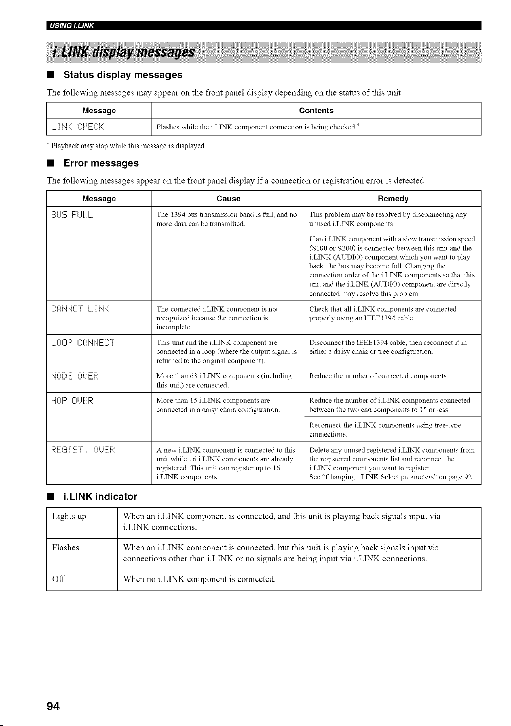
I_.Vf,T'flf_(h,r
• Status display messages
The following messages may appear on the front panel display depending on the status of this unit.
t Message Contents
i TMi,X f"i,,J i:Yf" b" Flashes while the i LINK conlponent connection is being checked.*
* Playback may stop while this message is displayed.
• Error messages
The following messages appear on the front panel display ifa connection o2" registration error is detected.
Message
E:i...i:!!!:{:::'UL,i.
Cause
The 1394 bus transmission band is full and no
more data can be transmitted.
,...=r"l_'-=f'MHf"'T' i TMb:.ll".%.., i i...i. _ '.'.. The connected i.LINK component is not
recognized because the connection is
incomplete.
i...,...,,...,li,".",i:::, ,....,...,i""'d"ii"ii:::"-'"i_',_......,..._ This ill]it and the iilNK colnponent are Disconnect the IEEEI394 cable, thell reconnect it in
connected in a loop (wheie the output signal is either a dais?, chain or tiee configuration
retmned to die original component)
i..i,"ff'.,i:::'......,_...._...,...,....._...r..""iii:::'_:::, More thall 63 i.LINK compo!lents (includin_ Reduce tile nllmbei of co!lnected componelltS
this unit) are connected.
i=Jf",i:;, f",i ii:7i::,
More dim] 15 i.LINK components are
connected in a daisy chain configuration
Remedy
This problem nlay be lesoh,ed by disconnecting any
unused i.LINK components.
If an iiINK component with a slow transmission speed
(S100 or $200) is connected between this unit and the
i.LINK (AUDIO) component which you want to play
back, the bus may become fifll. Changing the
connection order of the iLINK components so tllat this
unit and the i.LINK (AUDIO) component are directly
connected may resolve this problem.
Check that all i.LINK components are connected
properly using an IEEE1394 cable.
Reduce the number of i.LINK components connected
between the two end components to 15 or less
Reconnect the iLINK components using tree-t?lJe
co!lnections.
RE G ]i!!!:"["=, 0 i...iE e A new i. LINK component is connected to this Delete an?, mmsed *egistered iLINK components flora
lmit while 16 i.LINK components are aheady the *egistered components list and *econnect the
registered. This trait can iegister up to 16 i.LINK component you want to registei.
iLINK components See "Changing iLINK Select paiameteis" on page 92.
• i.LINK indicator
Lights up When an i.LINK component is connected, and this unit is playing back signals input via
iiINK connections.
Flashes When an i.LINK component is connected, but this unit is playing back signals input via
connections other than i.LINK or no signals are being input via i.LINK connections.
Off When no iiINK component is connected.
94
HDMI (High-Definition Multimedia Interface) is the first
industry-supported, uncompressed, all-digital AiV (audio/
video) interface.
Providing an interface between any AiV source (such as a
set-top box or AiV receiver) and an audio/video monitor
(such as a digital television DTV), HDMI supports
standard, enhanced or high-definition video as well as
multi-channel digital audio using a single cable.
HDMI transmits all ATSC HDTV standards and supports
8-channel digital audio, with bandwidth to spare to
accommodate future enhancements and requirements.
When used in combination with HDCP (High-bandwidth
Digital Content Protection), HDMI provides a secure
audio/video inter_ace that meets the security requirements
of content providers and system operators.
For further in_brmation on HDMI, visit the HDMI website
at "http: ,www.hdmi.orgi".
This unit's HDMI interface is based on the following
standards:
• HDMI 1.1 (High-Definition Multimedia Interl_ace
Specification Version 1.1) licensed by HDMI
Licensing, LLC.
• HDCP 1.1 (High-bandwidth Digital Content
Protection System Revision i. 1) licensed by Digital
Content Protection, LLC.
• Video or audio signals input at andio input jacks other than the
HDMI IN 1 or HDMI IN 2 jack cannot be outpm at the
HDMI OUT jack.
• (onnect the HDMI OUT jack of other components (such as a
DVD player) to the HDMI IN 1 or HDMI IN 2 jack of this trait.
Connect the HDMI OUT jack of this unit to the HDMI IN 1 or
HDMI IN 2 jack of other components (such as a prqiector).
• You need a conmlercially available HDMI cable to connect this
unit to other HDMI-compatible components. Use a HDMI cable
shorter than 5 m (15 if) to ensure stable operations and to
prevent losses of video qnalit3:
• This unit is not compatible with HDCP-incompatible HDMI or
DVI components.
• Use a conversion cable (HDMI jack +4- DVI-D jack) to connect
this unit to other DVI components.
• Digital video signals input at the HDMI IN 1 or HDMI IN 2
jack cannot be outpnt from analog video output jacks.
• GUI displays or analog video signals input at video input jacks
cannot be outpm at the HDMI OUT jack. To display analog
video signals, connect them to analog video output jacks.
• Audio signals input at input jacks other than the HDMI IN 1 or
HDMI IN 2 of this unit cannot be digitally output at the
HDMI OUT jack.
• This nnit is not compatible with multi-stereo area audio signals
of Snper Audio CDs. Yon can connect devices (such as a DVD
player) to the i.LINK jack or the MULTI CH INPUT jacks.
• When connected to a DVD player, audio signals may not be
output depending on the type of the DVD player. In case the
DVD player connected to this unit does not output DVD multi-
chamlel audio signals at the HDMI OUT jack, connect the DVD
player to the i.LINK jack or analog multi-chmmel audio input
jacks.
• When CPPM copy-protected DVD audio plays back, video and
audio signals may not be output depending on the Wpe of the
DVD player.
• Video and audio signals input at the HDMI IN 1 or HDMI IN 2
jack camlot be output at the HDMI OUT jack when this unit is
set to the standby mode or the power is turned off.
• When connecting other HDMI components to this unit. refer to
the instruction manuals i\_r those components.
• When HDMI audio signals are output from componeuts like a
DVD player, the audio signal ±Brmat (such as sampling
freqnencies) may be restricted depending on the HDMI video
signal format.
• Do not disconnect or cmmect the HDMI cable from this unit or
turn off the power of the HDMIiDVI components connected to
the HDMI OUT jack of this unit while data is being transferred.
Doing so may disrnpt playback or cause noise.
• HDMI compatibility with this unit
Audio signal Audio signal Compatible
HDMI
types formats
components
2ch Linem 2ch 32-192 kHz CD. DVD-Video
PCM 16/20/24 bit DVD-Audio. etc.
Multi-ch 5 1 ch, 32-96 kHz, DVD-Audio, etc
Linear PCM 16/20/24 bit
Bitstream Dolby Digital, DVD-Video, etc.
DTS
95
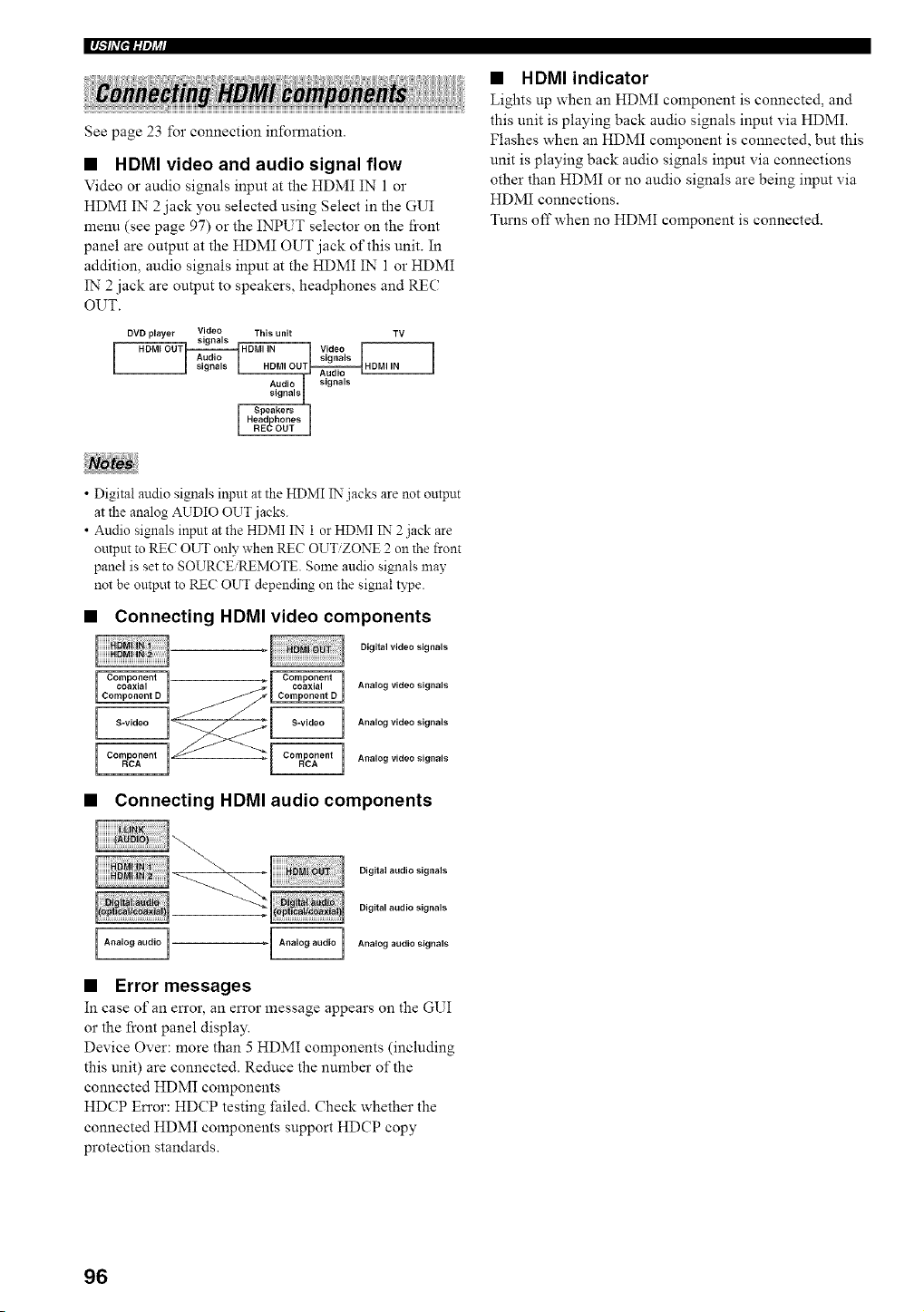
I_'lhYlilq?a
See page 23 for connection information.
• HDMI video and audio signal flow
Video o1"audio signals input at the HDMI IN 1 o1"
HDMI IN 2 jack you selected using Select in the GUI
menu (see page 97) or the INPUT selector on the fi'ont
panel are output at the HDMI OUT jack of this unit. In
a&lition, audio signals input at the HDMI IN 1 or HDMI
IN 2 jack are output to speakers, headphones and REC
OUT.
DVD p ayer Video Th s un TV
signals Video
signals
/_udio signals
• HDMI indicator
Lights up when an HDMI component is connected, and
this unit is playing back audio signals input via HDMI.
Flashes when an HDMI component is connected, but this
unit is playing back audio signals input via connections
other than HDMI or no audio signals are being input via
HDMI connections.
Turns offwhen no HDMI component is connected.
• Digital audio signals input at the HDMI IN jacks are not omput
at the analog AUDIO OUT j acks.
• Audio signals input at the HDMI IN 1 or HDMI IN 2 jack are
output to REC OUT only when REC OUTZONE 2 on the front
panel is set to SOURCE/REMOTE. Some audio signals may
not be output to REC OUT depending on the signal type.
• Connecting HDMI video components
Digital video signals
Analog video signals
Analog video signals
Analog video signals
• Connecting HDMI audio components
Digital audio signals
Digital audio signals
Analog audio signals
L=============J
• Error messages
In case of an error, an error message appears on the GUI
or the front panel display.
Device Over: more than 5 HDMI components (including
this unit) are connected. Reduce the number of the
connected HDMI components
HDCP Error: HDCP testing failed. Check whether the
connected HDMI components support HDCP copy
protection standards.
96
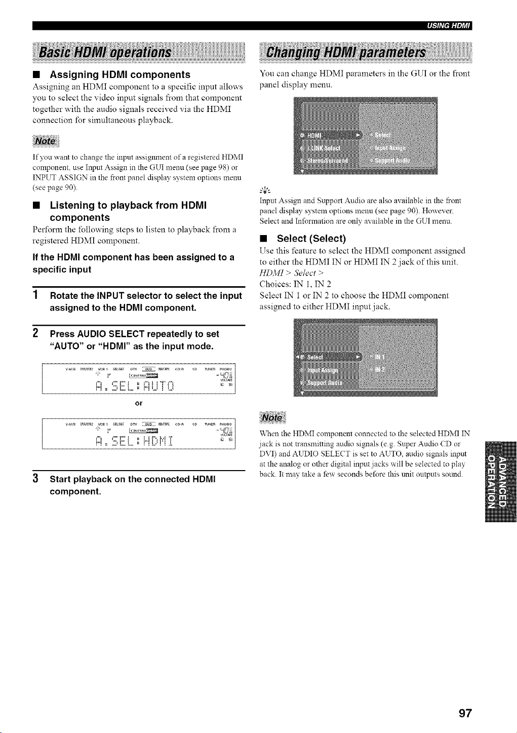
,l-'#,7111og_,
You can change HDMI parameters in the GUI or the front
panel display menu.
• Assigning HDMI components
Assigning an HDMI component to a specific input allows
you to select the video input signals from that component
together with the audio signals received via the HDMI
connection for simultaneous playback.
If you want to change the input assiglmlent of a registered HDMI
component, use Input Assign in the GUI menu (see page 98) or
INPUT ASSIGN in the front panel display system options menu
(see page 90).
• Listening to playback from HDMI
components
Perform the following steps to listen to playback from a
registered HDMI component.
If the HDMI component has been assigned to a
specific input
1 Rotate the INPUT selector to select the input
assigned to the HDMI component.
2 Press AUDIO SELECT repeatedly to set
"AUTO" or "HDMI" as the input mode.
or
wu× g'_R_l_ v_l r_t,s_ DTV _ _r_pE CDR e_ rU_E_ PUOUO]
m
3 Start playback on the connected HDMI
component.
Input Assign and Support Audio are also available in the front
panel display system options menu (see page 90). However,
Select and Information are only available in the GUI menu.
• Select (Select)
Use this feature to select the HDMI component assigned
to either the HDMI IN or HDMI IN 2 jack of this unit.
HDMI > Select >
Choices: IN i, IN 2
Select IN 1 or IN 2 to choose the HDMI component
assigned to either HDMI input jack.
When the HDMI component connected to the selected HDMI IN
jack is not transmitting audio signals (e.g. Super Audio CD or
DVI) and AUDIO SELECT is set to AUTO, audio signals input
at the analog or other digital input jacks will be selected to play
back. It may take a few seconds before this unit outputs sotmd.
97
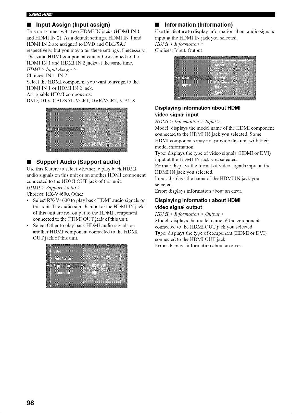
Im/-'if,,,'glil,ti_l
• Input Assign (Input assign)
This unit comes with two HDMI IN jacks (HDMI IN 1
and HDMI IN 2). As a default settings, HDMI IN 1 and
HDMI 1N 2 are assigned to DVD and CBLiSAT
respectively, but you may alter these settings if necessary.
The same HDMI component cannot be assigned to the
HDMI IN 1 and HDMI IN" 2 jacks at the same time.
HDMI > It_put Assigt_ >
Choices: IN 1, IN" 2
Select the HDMI component you want to assign to the
HDMI IN 1 or HDMI IN"2 jack.
Assignable HDMI components:
DVD, DTV, CBLiSAT, VCR1, DVR'VCR2, V-AUX
• Support Audio (Support audio)
Use this featnre to select whether to play back HDMI
audio signals on this unit or on another HDMI component
connected to the HDMI OUT jack of this unit.
HDMI > &lpport Audio >
Choices: RX-V4600, Other
• Select RX-V4600 to play back HDMI audio signals on
this unit. The audio signals input at the HDMI IN jacks
of this unit are not output to the HDMI component
connected to the HDMI OUT jack of this unit.
• Select Other to play back HDMI audio signals on
another HDMI component connected to the HDMI
OUT jack of this unit.
• Information (Information)
Use this feature to display information about audio signals
input at the HDMI IN jack you selected.
HDMI > Information >
Choices: Input, Output
Displaying information about HDMI
video signal input
HDMI > Informatio_ > It_put >
Model: displays the model name of the HDMI component
connected to the HDMI IN jack you selected. Some
HDMI components may not provide this unit with their
model information.
Type: displays the type of video signals (HDMI or DVI)
input at the HDMI IN jack you selected.
Format: displays the format of video signals input at the
HDMI IN jack you selected.
Input: displays the name of the HDMI IN jack you
selected.
Error: displays information about an en'or.
Displaying information about HDMI
video signal output
HDMI > I_formation > Output >
Model: displays the model name of the component
connected to the HDMI OUT jack you selected.
Type: displays the type of component (HDMI or DVI)
connected to the HDMI OUT jack.
Error: displays information about an en'or.
98
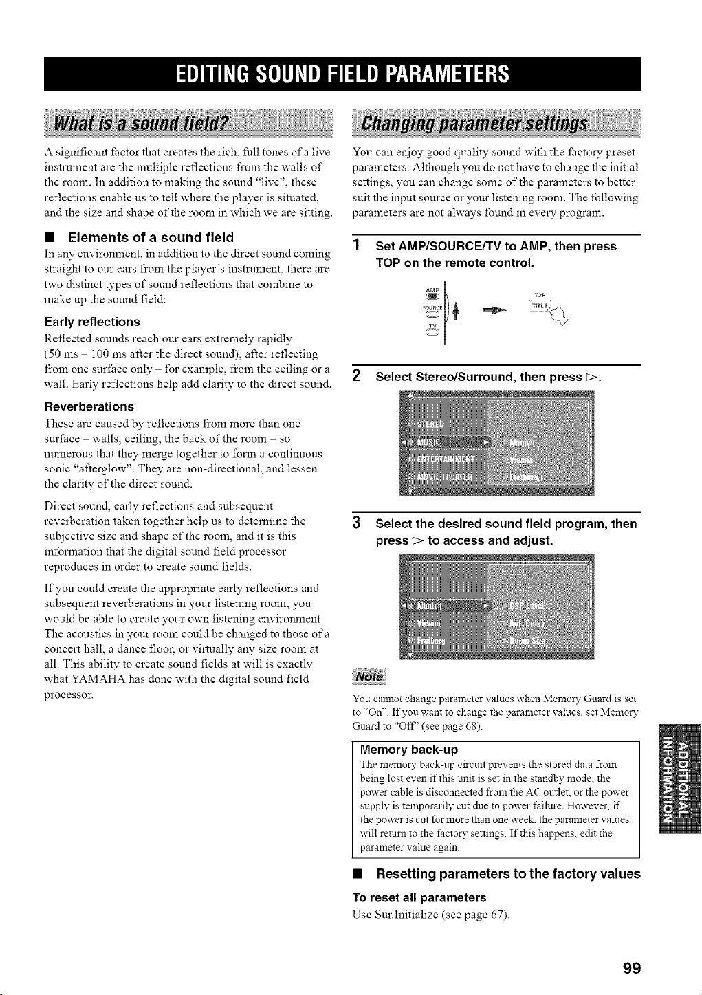
A significant factor that creates the rich, full tones of a live
instrument are the muhiple reflections from the walls of
the room. In addition to making the sound "live", these
reflections enable us to tell where the player is situated,
and the size and shape of the room in which we are sitting.
• Elements of a sound field
In any environment, in addition to the direct sound coming
straight to our ears from the player's instrument, there are
two distinct types of sound reflections that combine to
make up the sound field:
Early reflections
Reflected sounds reach our ears extremely rapidly
(50 ms 100 ms after the direct sound), after reflecting
from one surface only for example, from the ceiling or a
wall. Early reflections help add clarity to the direct sound.
Reverberations
These are caused by reflections from more than one
surface walls, ceiling, the back of the room so
numerous that they merge together to form a continuous
sonic "afterglow". They are non-directional, and lessen
the clarity of the direct sound.
Direct sound, early reflections and subsequent
reverberation taken together help us to determine the
subjective size and shape of the room, and it is this
information that the digital sound field processor
reproduces in order to create sound fields.
If you could create the appropriate early reflections and
subsequent reverberations in your listening room, you
would be able to create your own listening environment.
The acoustics in your room could be changed to those of a
concert hall, a dance floor, or virtually any size room at
all. This ability to create sound fields at will is exactly
what YAMAHA has done with the digital sound field
proeessoE
You can enjoy good quality sound with the _actory preset
parameters. Although you do not have to change the initial
settings, you can change some of the parameters to better
suit the input source or your listening room. The following
parameters are not always found in every program.
Set AMP/SOURCE/TV to AMP, then press
TOP on the remote control.
++°p+÷
++
2 Select Stereo/Surround, then press_>.
3 Select the desired sound field program, then
press _> to access and adjust.
You cannot change parameter values when Memory Guard is set
to "On". If you want to change the parameter values, set Memory
Guard to "Oft_' (see page 68)+
Memory back-up
The memo D"back-up circuit prevents the stored data from
being lost even if this unit is set in the standby mode, the
power cable is disconnected from the AC outlet, or the power
supply is temporarily cut due to power _hilure. However, if
the power is cut for more than one week. the parameter values
will return to the factory settings. If this happens, edit the
parameter value again.
• Resetting parameters to the factory values
To reset all parameters
Use Sur.Initialize (see page 67).
99
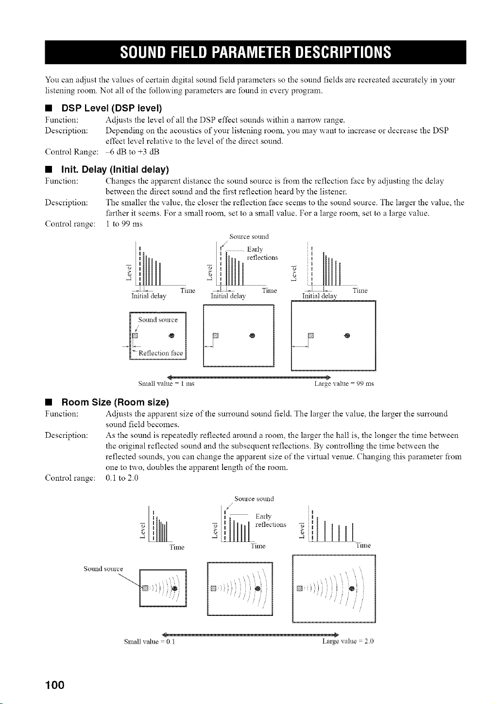
You can adjust the values of certain digital sound field parameters so the sound fields are recreated accurately in your
listening room. Not all of the following parameters are found in every program.
• DSP Level (DSP level)
Function: Adjusts the level of all the DSP effect sounds within a narrow range.
Description: Depending on the acoustics of your listening room, you may want to increase or decrease the DSP
effect level relative to the level of the direct sound.
Control Range: 6 dB to +3 dB
• Init. Delay (Initial delay)
Function: Changes the apparent distance the sound source is fi'om the reflection face by adjusting the delay
between the direct sound and the first reflection heard by the listener.
Description: The smaller the value, the closer the reflection face seems to the sound source. The larger the value, the
_arther it seems. For a small room, set to a small value. For a large room, set to a large value.
Control range: 1 to 99 ms
Time
Initial delay
i So.nd _o=roe1
°
Sollrce sollnd
Early
reflections
Time
Initial delay
I
I
I
_ Time
Initial delay
Small value = I ms Large value = 99 ms
• Room Size (Room size)
Function: Adjusts the apparent size of the surround sound field. The larger the value, the larger the surround
sound field becomes.
Description: As the sound is repeatedly reflected around a room, the larger the hall is, the longer the time between
the original reflected sound and the subsequent reflections. By controlling the time between the
reflected sounds, you can change the apparent size of the virtual venue. Changing this parameter from
one to two, doubles the apparent length of the room.
0.1 to 2.0
Control range:
Time
SOllrcesolmd
/
Early
reflections
Time
I
Time
Sound source
Small value = 0 1 Large value = 2.0
100
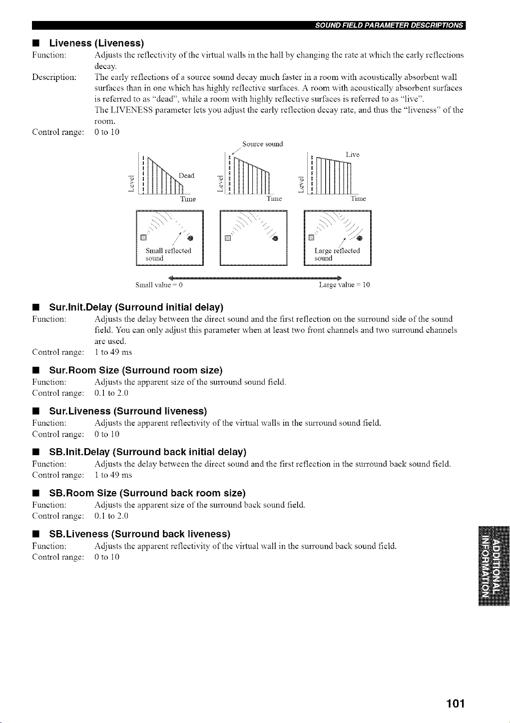
• Liveness
Function:
Description:
Control range:
(Liveness)
Adjusts the reflectivity of the virtual walls in the hall by changing the rate at which the early reflections
decay.
The early reflections of a source sound decay much faster in a room with acoustically absorbent wall
surfaces than in one which has highly reflective surfaces. A room with acoustically absorbent surfaces
is referred to as "dead", while a room with highly reflective surfaces is referred to as "live".
The LIVENESS parameter lets you adjust the early reflection decay rate, and thus the "liveness" of the
rooln.
0to 10
uu ead
_o
Time
Sollrce sollnd
J
J
Live
Time Time
I Small reflected
sound
4
Small value = 0 Large value = l0
• Sur.lnit.Delay (Surround initial delay)
Function: Adjusts the delay between the direct sound and the first reflection on the surround side of the sound
field. You can only adjust this parmneter when at least two fi'ont channels and two surround channels
are used.
Control range: 1 to 49 ms
• Sur.Room Size (Surround room size)
Function: Adjusts the apparent size of the surround sound field.
Control range: 0.1 to 2.0
• Sur.Liveness (Surround liveness)
Function: Adjusts the apparent reflectivity of the virtual walls in the surround sound field.
Control range: 0 to 10
• SB.Init.Delay (Surround back initial delay)
Function: Adjusts the delay between the direct sound and the first reflection in the surround back sound field.
Control range: 1 to 49 ms
• SB.Room Size (Surround back room size)
Function: Adjusts the apparent size of the surround back sound field.
Control range: 0.1 to 2.0
• SB.Liveness (Surround back liveness)
Function: Adjusts the apparent ref!ectivity of the virtual wall in the surround back sound field.
Control range: 0 to 10
101
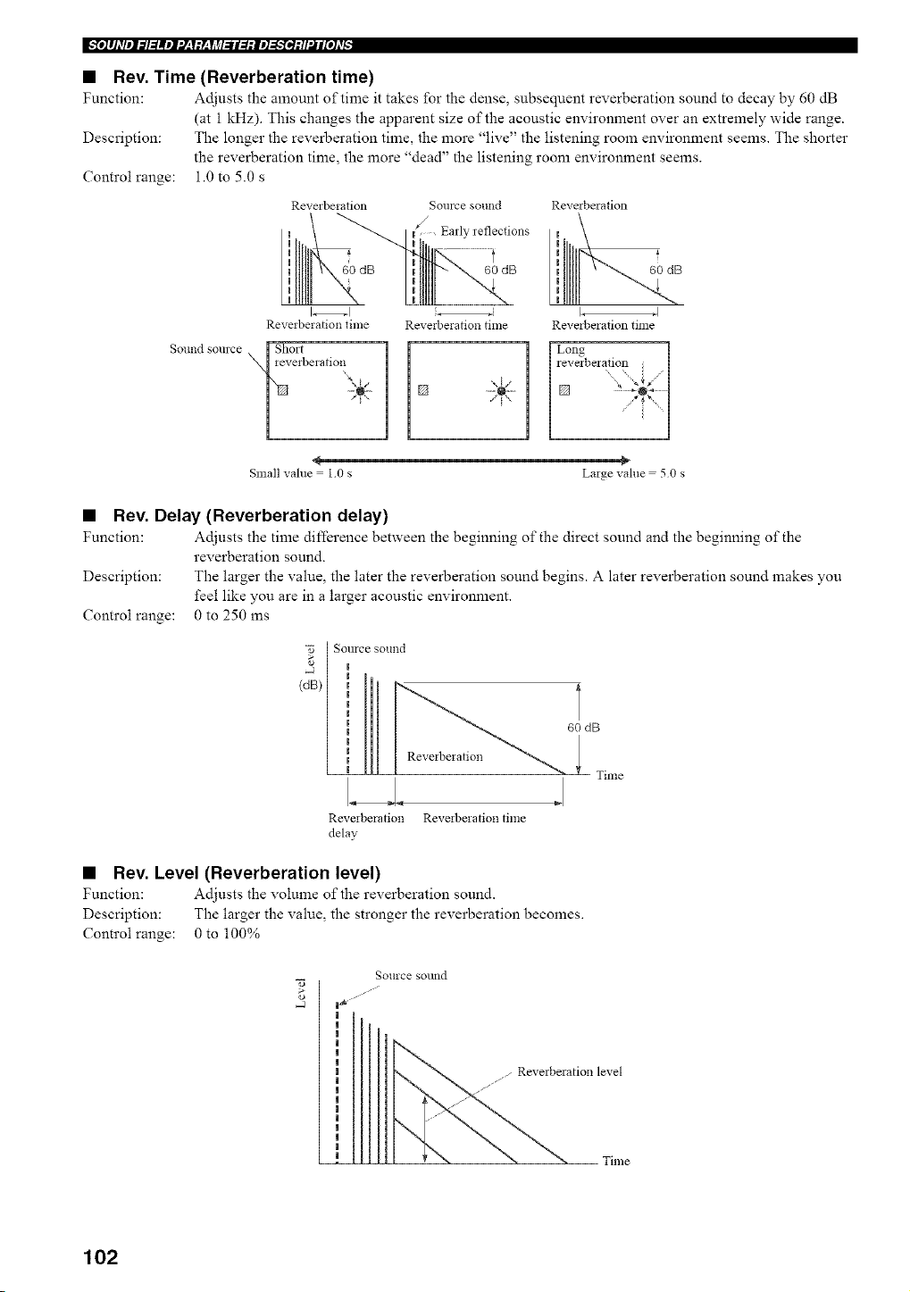
Ir_e]#Jdlel_l:lllel'J:Y:r:YJ_l_ll:l:ie]_:/l'.Jl[e]d_:
• Rev. Time (Reverberation time)
Function: Adjusts the amount of time it takes for the dense, subsequent reverberation sound to decay by 60 dB
(at 1 kHz). This changes the apparent size of the acoustic environment over an extremely wide range.
Description: The longer the reverberation time, the more "live" the listening room environment seems. The shorter
the reverberation time, the more "dead" the listening room environment seems.
Control range: 1.0 to 5.0 s
Solllld SOllrce
Reverbeiation Source sound
Early reflections
/
60 dB 60 dB
Reverberation
Reveiberation time
Short
ieveiberatim}
Reveibeiation time Reverberation time
_5_V
60 dB
<
Small value = I0 s Lage value = 50 s
• Rev. Delay (Reverberation delay)
Function: Adjusts the time difference between the beginning of the direct sound and the beginning of the
reverberation sound.
Description: The larger the value, the later the reverberation sound begins. A later reverberation sound makes you
feel like you are in a larger acoustic environment.
Controlrange: 0 to 250 ms
[ SOllrce SOtllld
(dB)
6O dB
Time
Revmberation Reveiberation time
delay
• Rev. Level (Reverberation level)
Function: Adjusts the volume of the reverberation sound.
Description: The larger the value, the stronger the reverberation becomes.
Controlrange: 0 to 100%
Source sollnd
ation level
, Time
102
• Dialogue Lift (Dialog lift)
Funetion: Adjusts the height of the front and center channel sounds by assigning some of the front and center
chmmel elements to the presence speakers.
Description: The larger the parameter, the higher the position of the front and center channel sound.
Choices: 0, 1, 2, 3, 4, 5
For 7ch Stereo
Function: Adjusts the volume level _br each channel in 7-channel stereo mode.
Control range: 0 100%
Center Level (Center level)
Surround L Level (Surround left level)
Surround R Level (Surround right level)
Sur. Back Level (Surround back level)
Presence L Level (Presence left level)
Presence R Level (Presence right level)
For PLII[x Music and PLII Music
Panorama (Panorama)
Function: Extends the front stereo image to include the sun'ound speakers for a wraparound effect.
Choices: Off, On
Dimension (Dimension)
Function: Gradually adjusts the sound field either towards the front or towards the rear.
Control range: 3 (towards the rear) to +3 (towards the front), initial setting is STD (standard)
Center Width (Center width)
Function: Adjusts the center image from all three front speakers to varying degrees.
A larger value adjusts the center image towards the front left and right speakers.
Control range: 0 (center channel sound is output only from center speaker) to 7 (center channel sound is output only
from front left and right speakers), initial setting is 3
For Neo:6 Music
Center Image (Center image)
Function: Adjusts the center image from all three front speakers to varying degrees.
Control range: 0.0 to 1.0
For SRS Circle Surround H
FOCUS
Function:
Control range:
TruBass
Function:
Control range:
Adjusts the clearness of a sound image by elevating the perception of the sound image to compensate
for non-optimally placed speakers fi'om a lower location.
A larger value makes speakers sound as if they are positioned at ear level.
0to 8
Adjusts the lower register by producing the perception of improved low frequency peribrmance.
A larger value improves bass even without a subwoofer and provides deeper, richer bass in the presence
of a subwoofer.
0to 8
103
Ir_e]#Jdlel_l:lllel'J:Y:r:YJ_l_ll:l:ie]_:/l'.Jl[e]d_:
• Decode Type (Decoder type)
For MOVIE THEATER
Function: Selects the decoder used to playback 2-channel sources using MOVIE THEATER programs.
Choices: Pro Logic Pro Logic II Pro LogicIIx Neo:6
For THX Cinema
Function: Selects the decoder used to playback 2-channel sources using THX Cinema.
Choices: Pro Logic Pro Logic 1I Pro LogicI[x Neo:6
For SURROUND Standard
Function: Selects the decoder used to playback 2-channel sources using SURROUND Standard.
Choices: Pro Logic / PLllMovie / PLIlMusic / PLIIGame / PLIIx Movie / PLIIx Music / PLIIx Game /
Neo:6 Cinema / Neo:6 Music CS lI Cinema* / CS II Music* (* U.S.A. model only)
For SURROUND Enhanced
Function: Selects the decoder used to playback 2-channel sources using SURROUND Enhanced.
Choices: Pro Logic Pro Logic II Pro LogiclIx Neo:6
Pro LogiclIx appears when the surround back speakers are available, and Pro Logic H appears when the surround back speakers are not
available.
• Initialize (Initialize)
Function: Initializes the parameters for each sound field subprogram.
Choices: NO, YES
Note
If you want to initialize all of the parameters within a sound field program group, use Sur.Initialize (see page 67).
104
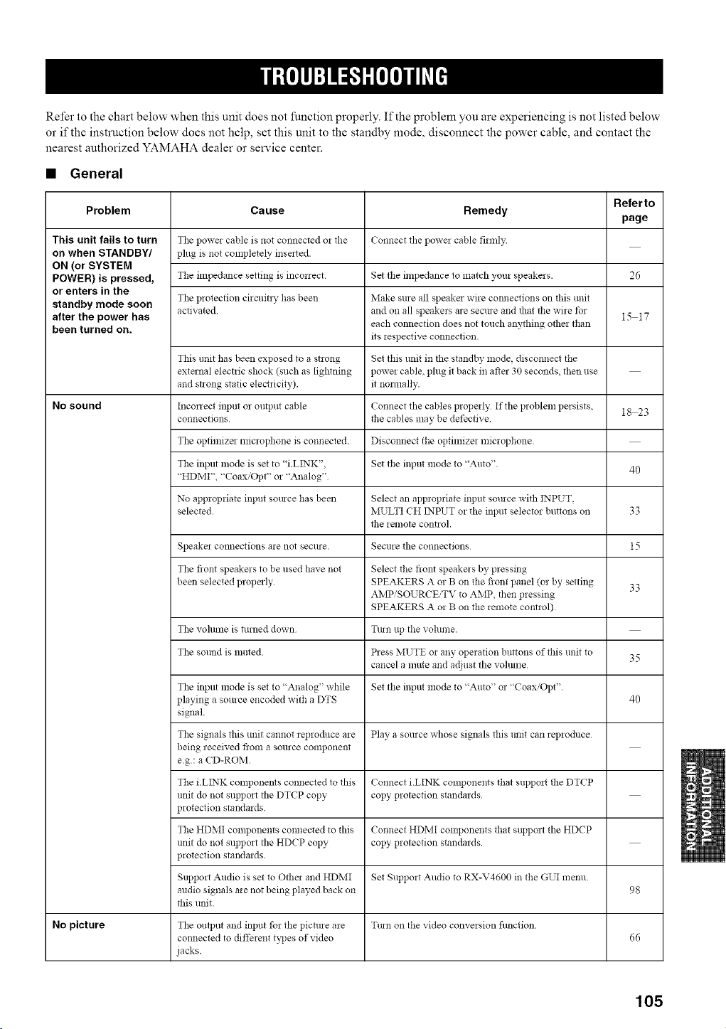
Refer to the chart below when this unit does not function properly. If the problem you are experiencing is not listed below
or if the instruction below does not help, set this unit to the standby mode, disconnect the power cable, and contact the
nearest authorized YAMAHA dealer or service center.
• General
Referto
Problem Cause Remedy
page
This unit fails to turn The power cable is not connected oi the Connect the powe_ cable firmly
on when STANDBY/ plug is not completely inserted.
ON (or SYSTEM
POWER) is pressed, Tile impedance setting is inconect Set the impedance to match your speakels. 26
or enters in the
standby mode soon The plotection circuitly has been Make sule all speaker wire cmmections on this unit
after the power has activated and on all speakels are secule and that the wire tbr 15 17
each connection does not touch anything othei than
been turned on. its iespective connection.
This unit has been exposed to a strong Set this unit in the standby mode, disconnect the
external electric shock (such as lightning powei cable, phlg it back in after 30 seconds, then use
and strong static electricity), it normally.
No sound Inconect input or output cable Connect the cables properly If the problem persists, 18 23
connections the cables may be defective
The optimizer microphone is connected. Disconnect the optimize* microphone
The input mode is set to "i.LI2",TK", Set the input mode to "Auto". 40
"HDMI", "Coax,'Opt" or "Analog"
No appropriate input sotuce has been Select an appropriate input source with INPUT,
selected. MULTI CH INPUT o! the input selector buttons on 33
the *emote control.
Speaker comlections are not secure. Secure the connections 15
The front speakers to be used have not Select the front speakeis by pressing
been selected properly. SPEAKERS A or B on the front panel (or by setting 33
AMP'SOURCE/TV to AMP, then pressing
SPEAKERS A o! B on the remote control)
The vohnne is turned down Ttun tip the volume.
The sound is muted. Press MUTE oi any opeiation buttons of this unit to 35
cancel a mute and adjust the vohlme
The input mode is set to "Analog" while Set the input mode to "Auto" or "Coax/Opt".
playing a source encoded with a DTS 40
signal.
The signals this unit cannot reproduce aie Play a source whose signals this unit can repioduce
being received from a source component
e.g.: a CD-ROM.
The i.LINK components connected to this Connect i.LINK colnponents that suppolt the DTCP
unit do not support the DTCP copy copy protection standards.
protection standaids
The HDMI components connected to this Connect HDMI components that support the HDCP
unit do not support the HDCP copy copy protection standards.
protection standaids
r
Support Audio is set to Othei and HDMI Set Support Audio to RX-V4600 in the GUI menu
audio signals aie not being played back on 98
this unit.
No picture The output and input for the picture are Ttun on the video conversion filnction
connected to diffeient b]Jes of video 66
jacks.
105
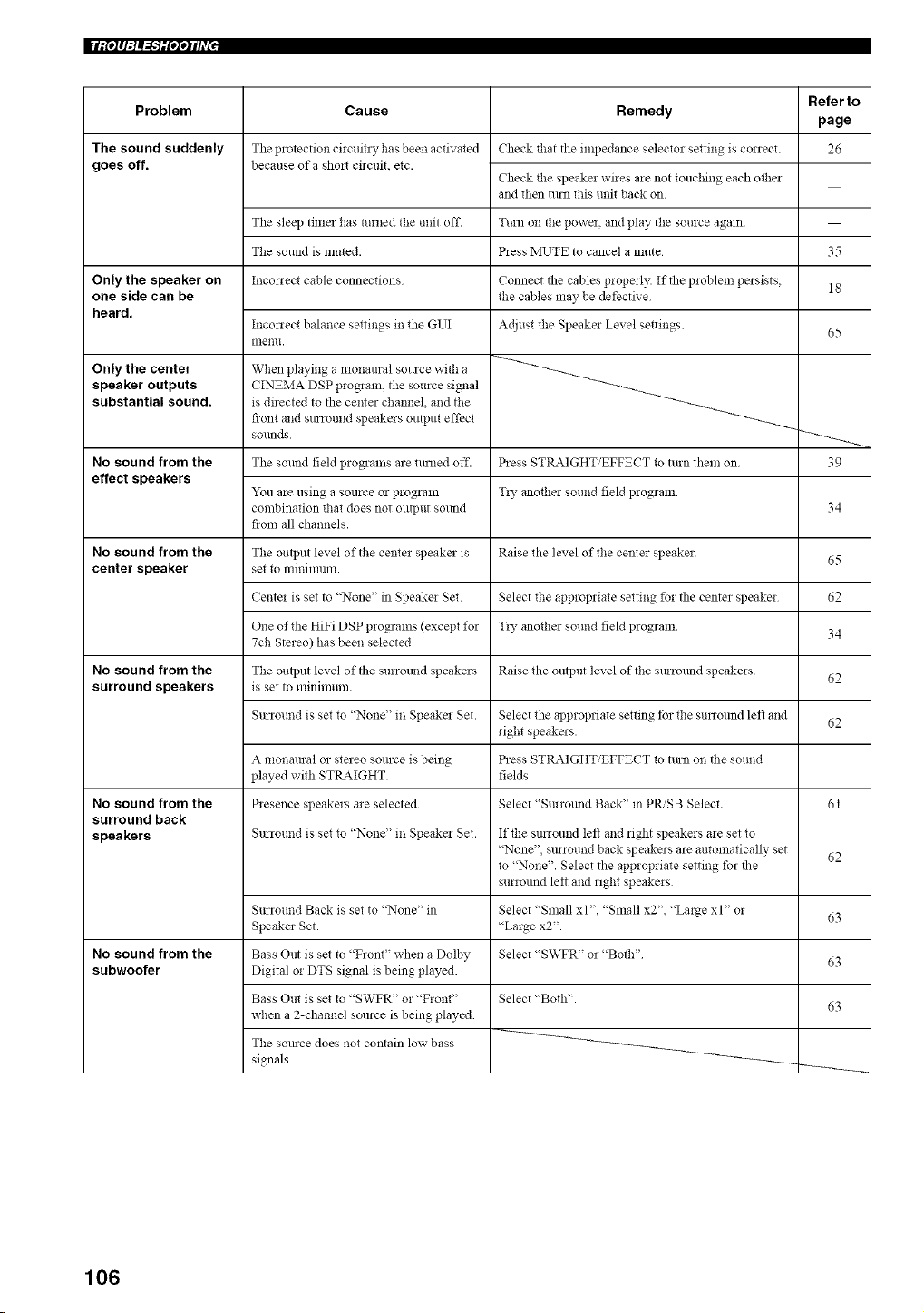
IIIit°l q:lA1"T'lilqqlhVl •
Problem
The sound suddenly
goes off.
Only the speaker on
one side can be
heard.
Only the center
speaker outputs
substantial sound.
No sound from the
effect speakers
No sound from the
center speaker
No sound from the
surround speakers
No sound from the
surround back
speakers
No sound from the
subwoofer
Cause Remedy
The protection circuit_ T ha s been activated
because ofa sho_ circuit, etc.
Check that the impedance selector setting is correct
Check the speaker wires are not touching each other
and then turn this unit back on
The sleep tima has turned the unit off. Turn on the powa, and play the source a gain
The sound is muted. Press MUTE to cancel a mute
Inconect cable connections
Inconect balance settings in the GUI
Illenll.
When playing a monanral somce with a
CINEMA DSP program, the source signal
is directed to the center channel, and the
front and surround speakms output effect
SOllnds
Connect the cables properly. If the problem pmsists,
the cables may be dethctive
Adjust the Speakm Level settings.
The sound field programs are mined off. Press STRAIGHT/EFFECT to turn them on
You are using a somce or program T_y anothm sound field program.
combination that does not output sound
fiom all channels.
The output level of the center speaker is Raise the level of the center speaker
set 1o nlinilnllm.
Center is set to "None" in Speaker Set Select the appropriate setting %r the center speaker
One of the HiFi DSP programs (except for T_y another sound field program
7ch Stereo) has been selected
The output level of the surrolmd speakms Raise the output level of the smround speakers
is set to minimum.
SmTound is set to "None" in Speaker Set.
A monamal or steleo somce is being
played with STRAIGHT
Presence speakers are selected
Select the appropriate setting for the sunound left and
fight speakers.
Press STRAIGHT/EFFECT to tttm on the sound
fields
Select "Surround Back" in PR/SB Select.
Smround is set to "None" in Speaker Set.
SmTound Back is set to "None" in
Speaker Set.
Bass Out is set to "Front" when a Dolby
Digital or DTS signal is being played.
Bass Out is set to "SWFR" or "Front"
when a 2-channel source is being played
The somce does not contain low bass
signals
If the smTound left and right speakers are set to
"None" smTound back speakas me antomafically set
to "None". Select the aplJropriate setting for the
surround left and right speakers
Select "Small xl", "Small x2", "Large xl" or
"Large x2".
Select "SWFR" or "Both"
Select "Both".
Refer to
page
26
35
18
65
39
34
65
62
34
62
62
61
62
63
63
63
106
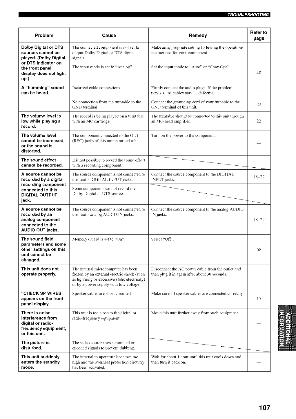
If_q_=_iNqif_
Problem
Dolby Digital or DTS
sources cannot be
played. (Dolby Digital
or DTS indicator on
the front panel
display does not light
up.)
A "humming" sound
can be heard.
The volume level is
low while playing a
record.
The volume level
cannot be increased,
or the sound is
distorted.
The sound effect
cannot be recorded.
A source cannot be
recorded by a digital
recording component
connected to this
DIGITAL OUTPUT
jack.
A source cannot be
recorded by an
analog component
connected to the
AUDIO OUT jacks.
The sound field
parameters and some
other settings on this
unit cannot be
changed.
This unit does not
operate properly.
"CHECK SP WIRES"
appears on the front
panel display.
There is noise
interference from
digital or radio-
frequency equipment,
or this unit.
Cause
The connected component is not set to
omput Dolby Digital or DTS digital
signals
The input mode is set to "Analog"
Incorrect cable coimecfions
No connection flom the turntable to the
GND terminal.
The record is being played on a turntable
with an MC cmtridge
The COlnponent connected to the OUT
(REC) jacks of this unit is turned oil:
It is not possible to record the sound effect
with a recording component.
The source component is not connected to
this :mit's DIGITAL INPUT jacks.
Solne conlponents cannot record the
Dolby Digital or DTS sources
The source component is not connected to
this unit's analog AUDIO IN jacks.
Memory Guard is set to "On"
The internal microcomputer has been
frozen by an external electric shock (such
as lighming or excessive static electricity)
or by a powa supply with low voltage
Speaker cables are short circuited.
This unit is too close to the digital or
radio-fiequency equipment.
Remedy
Make an approp:iate setting following the ope:ations
instructions for your component
Set the input mode to "Auto" or "Coax/Opt".
Firmly connect the andio phlgs If the problem
persists, the cables may be defective
Connect the grounding cord of your turnable to the
GND terminal of tiffs unit
The turntable should be connected to this unit thlough
an MC-head amplifier
Tun on the power to the component.
Connect the source component to the DIGITAL
INPUT jacks
Connect the source component to the analog AUDIO
IN jacks.
Select "OFF'.
Disconnect the AC power cable flom the outlet and
then phlg it in again after about 30 seconds.
Make sure all speaker cables are connected conectly
Move this unit fi:rtha away from such equipment.
Referto
page
40
22
22
18 22
18 22
68
The picture is The video source uses scrambled or
disturbed, encoded signals to prevent dubbing.
This unit suddenly The internal temperatme becomes too Wait for about 1 horn until this unit cools down and
enters the standby high and the overheat protection circuit:y then turn it back on.
mode. has been activated.
107
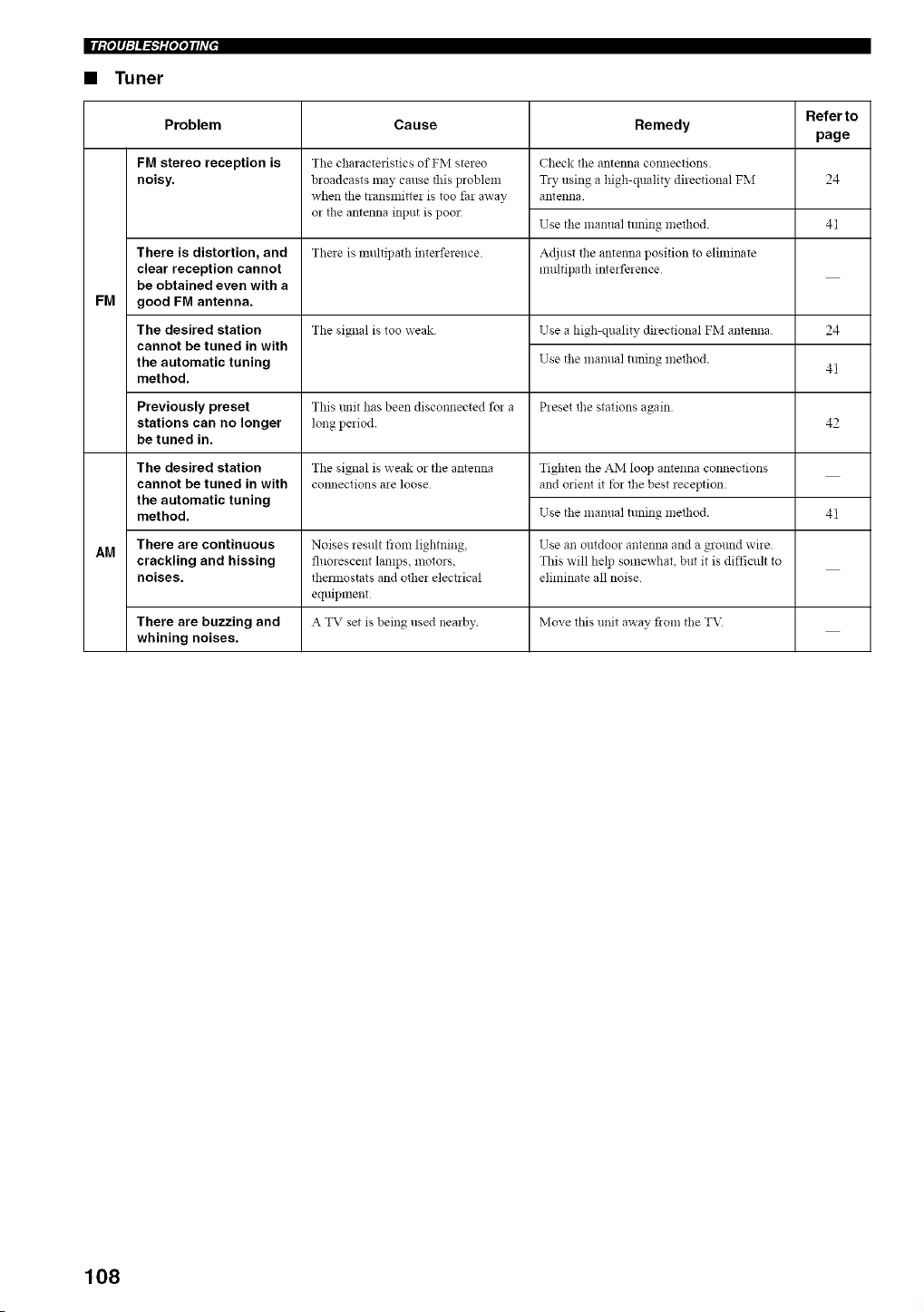
|lit°l q_ _"T_ilq'tlh_l •
• Tuner
Referto
Cause Remedy
page
24
FM
Problem
FM stereo reception is
noisy.
There is distortion, and
clear reception cannot
be obtained even with a
good FM antenna.
The desired station
cannot be tuned in with
the automatic tuning
method.
The characteristics of FM stereo
broadcasts may canse this problem
when the transmitter is too far away
or the antenna input is poor
Check tile antenna connections.
TD, using a high-quality directional FM
antenna
Use tile manual tuning method. 41
There is multipa_h interference Adjust the antenna position to eliminate
multipath interference
The signal is too weak Use a high-quality directional FM antenna
Use the manual tuning method.
24
41
Previously preset This trait has been disconnected for a Preset the stations again
stations can no longer long period. 42
be tuned in.
The signal is weak or the antenna
connections are loose
Tighten the AM loop antenna connections
and orient it for the best reception
Use the manual tuning method.
The desired station
cannot be tuned in with
the automatic tuning
method.
41
There are continuous Noises result from lightning, Use an outdoor antenna and a ground wire.
AM
crackling and hissing fluorescent lamps, motors, This will help somewhat, but it is dift'icult to
noises, them'tostats and other electrical eliminate all noise
equipment
There are buzzing and A TV set is being used nearby. Move this unit away flora the T\:
whining noises.
108
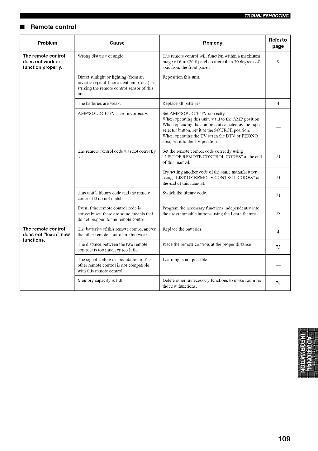
rfP_q:l_'liNqih7 J
• Remote control
Referto
Problem Cause Remedy
page
The remote control W'!ong distance or angle The _emote contzol will fimction within a maximmn
does not work or range of 6 m (20 ft) and no mole than 30 degrees off- 9
function properly, axis from the front panel.
Direct sunlight or lighting (fronI a51 Reposition this unit
invelter type of fluorescent lamp, etc.) is
striking the remote control sensor of this
unit.
The batteries are weak. Replace all batteries. 4
AMPiSOURCEiTV is set incorrectly
Tile remote cont!ol code was not con ectly
set.
Set AMPiSOURCEiTV conectly.
When operating this unit, set it to the AMP position.
When operating the component selected by tile input
selector button, set it to the SOURCE position.
When operating the TV set in the DTV or PHONO
area, set it to tile TV position
Set the remote control code conectly using
"LIST OF REMOTE CONTROL CODES" at the end
of this mamlal.
T_y setting another code of the same manufactmer
using "LIST OF REMOTE CONTROL CODES" at
the end of this manual.
This unit's library code and the remote Switch the libral 3, code.
cont!ol ID do not match
Even if the remote control code is Program the necessal_ fimctions independently into
correctly set, there are some models that the programmable buttons using the Learn feature.
do not respond to the remote cont!ol.
The remote control The batteries of this relnote control and/or Replace tile batteries
does not "learn" new the othel remote control are too weak
functions.
The distance between the two lemote Place the lemote contlols at the ploper distance
cont!ols is too much or too little.
Tile signal coding or modulation of the Learning is not possible.
other remote control is not compatible
with this remote control.
Memo13 capacity is fifll. Delete other mmecessal 3, fimctions to make room t_r
the new fimctions.
71
71
71
73
4
73
78
109
• Dolby Digital
Dolby Digital is a digital surround sound system that gives
you completely independent multi-channel audio. It
provides 5 full-range audio channels; 3 front channels
(left, center, and right), and 2 surround stereo channels.
An additional channel especially for bass effects, called
LFE (low fi'equency effect) is also provided giving the
system a total of 5.1-channels (LFE is counted as a 0.1
channel). By using 2-channel stereo for the surround
speakers, more accurate moving sound effects and
surround sound environment are possible than with Dolby
Surround. The wide dynamic range (maximum to
minimum volume) reproduced by the 5 full-range
channels and the precise sound orientation generated
using digital sound processing provide listeners with a
previously unheard of excitement and realism.
• Dolby Digital EX
Dolby Digital EX creates 6 full-bandwidth output
channels from 5.1-channel sources. This is done by using
a matrix decoder that derives 3 surround channels from
the 2 in the original recording. For best results, Dolby
Digital EX should be used with movie sound tracks
recorded with Dolby Digital Surround EX. With this
a&litional channel, you can experience more dynamic and
realistic moving sound especially with scenes that have
"flyover" and "fly-around" effects.
• Dolby Pro Logic ii
Dolby Pro Logic II is an improved technique used to
decode vast numbers of existing Dolby Surround
software. This new technology enables a 5-channel
playback with 2 front left and right channels, 1 center
channel, and 2 surround left and right channels (instead of
only 1 surround channel for conventional Pro Logic
technology). Music and Game modes are also available
for 2-channel sources in addition to the Movie mode.
• Dolby Pro Logic Ilx
Dolby Pro Logic lg x is a new technology enabling 6.1 or
7.1 multi-channel playback from 2-channel or multi-
channel sources. There is a Music mode for music, a
Movie mode for movies and a Game mode for games.
to reproduce realistic and dynamic sound effects: 2 front
left and right channels (stereo), a center channel for dialog
(monaural), and a surround channel for special sound
effects (monaural). The surround channel reproduces
sound within a narrow frequency range.
Dolby Surround is widely used with nearly all video tapes
and laser discs, and in many TV and cable broadcasts as
well. The Dolby Pro Logic decoder built into this unit
employs a digital signal processing system that
antomatically stabilizes the volume on each channel to
enhance moving sound effects and directionality.
• DSD
Direct Stream Digital (DSD) technology stores audio
signals on digital storage media, such as Super Audio
CDs. Using DSD, signals are stored as single bit values at
a high-frequency sampling rate of approximately 2.8224
MHz, while noise shaping and oversampling are used to
reduce distortion, a common occurrence with very high
quantization of audio signals. Due to the a high sampling
rate, better audio qnality can be achieved than that offered
by the PCM format used for normal audio CDs.
• DTS 96/24
DTS 9624 offers an unprecedented level of audio quality
for multi-channel sound on DVD-Video, and is fully
backward-compatible with all DTS decoders. "96" refers
to a 96 kHz sampling rate (compared to the typical 48 kHz
sampling rate). "24" refers to 24-bit word length.
DTS 96/24 offers sound quality transparent to the original
96/24 master, and 96/24 5.1-channel sound with
full-quality full-motion video for music programs and
motion picture soundtracks on DVD-video.
• DTS (Digital Theater Systems)
Digital Surround
DTS digital surround was developed to replace the analog
soundtracks of movies with a 6-channel digital sound
track, and is now rapidly gaining popularity in movie
theaters around the world. Digital Theater Systems Inc.
has developed a home theater system so that you can
enjoy the depth of sound and natural spatial representation
of DTS digital surround in your home. This system
produces practically distortion-i_cee 6-channel sound
(technically, left, right and center channels, 2 surround
channels, plus an LFE 0.1 channel as a subwoofer, for a
total of 5.1-channels). This unit incorporates a DTS-ES
decoder that enables 6.1- channel reproduction by adding
a surround back channel to the existing 5.1-channel
format.
110
• Neo:6
Neo:6 decodes conventional 2-channel sources for
6 channel playback by. It enables playback with the full-
range channels with higher separation comparable to
digital discrete signal playback. Two modes are available;
"Music mode" for playing nmsic sources and "Cinema
mode" l'or movies.
• PCM (Linear PCM)
Linear PCM is a signal lbnnat under which an analog
audio signal is digitized, recorded and transmitted without
using any compression. This is used as a method of
recording CDs and DVD audio. The PCM system uses a
technique for sampling the size of the analog signal per
very small unit of time. Standing for "pulse code
modulation", the analog signal is encoded as pulses and
then modulated for recording.
• SRS CS ii (SRS Circle Surround II)
SRS CS I1 (SRS Circle Surround ll) is a
high-performance 6.1 channel matrix surround sound
decoding system. It is the next-generation of the original
SRS Circle Surround technology, incorporating powerful
industry-first features including the dialog clarity
enhancement technology and added cinema-like bass to
the front channels and subwoofer.
• CINEMA DSP
Since the Dolby Surround and DTS systems were
originally designed for use in movie theaters, their effect
is best felt in a theater having many speakers and designed
l'or acoustic effects. Since home conditions, such as room
size, wall material, number of speakers, and so on, can
differ so widely, it's inevitable that there are differences in
the sound heard. Based on a wealth of actually measured
data, YAMAHA CINEMA DSP uses YAMAHA original
sound field technology to combine Dolby Pro Logic,
Dolby Digital and DTS systems to provide the visual and
audio experience of a movie theater in the listening room
of your own home.
• SILENT CINEMA
YAMAHA has developed a natural, realistic sound effect
DSP algorithm for headphones.
Parameters for hea@hones have been set for each sound
field so that accurate representations of all the sound field
programs can be enjoyed on headphones.
• Virtual CINEMA DSP
YAMAHA has developed a Virtual CINEMA DSP
algorithm that allows you to enjoy DSP sound field
surround effects without any surround speakers by using
virtual surround speakers.
It is even possible to enjoy Virtual CINEMA DSP using a
minimal two-speaker system that does not include a center
speaker.
qiN'_G_lli
• ASA (Advanced Speaker Array)
ASA is a proprietary THX technology which processes
the sound fed to 2 side and 2 back surround speakers to
provide the optimal surround sound experience. When you
set up your home theater system using all eight speaker
outputs (Left, Center, Right, Surround Right, Surround
Back Right, Surround Back Left, Surround Left and
Subwoofer) placing the two Surround Back speakers close
together facing the fi'ont of the room will provide the
largest sweet spot. If for practical reasons you have to
place the Surround Back speakers apart, you will need to
go THX Audio Set-up screen and choose the setting that
most closely corresponds to the speaker spacing, which
will re-optimized the surround sound-field.
ASA is used in three new modes: THX Select2 Cinema,
THX Music Mode and THX Gmnes Mode.
• ITU-R
ITU-R is the radio communication sector of the IT[?
(International Telecommunication Union). ITU-R
recommends a standard speaker placement which is used
in many critical listening rooms, such as mastering
studios.
• LFE 0.1 channel
This channel is for the reproduction of low bass signals.
The frequency range for this channel is 20 Hz to 120 Hz.
This channel is counted as 0.1 because it only enforces a
low frequency range compared to the full-range
reproduced by the other 5/6 channels in Dolby Digital or
DTS 5.1/6.1-channel systems.
• Sampling frequency and number of
quantized bits
When digitizing an analog audio signal, the mlmber of
times the signal is sampled per second is called the
sampling frequency, while the degree of fineness when
converting the sound level into a numeric value is called
the number of quantized bits.
The range of rates that can be played back is determined
based on the sampling rate, while the dynamic range
representing the sound level difference is determined by
the number of quantized bits. In principle, the higher the
sampling frequency, the wider the range of frequencies
that can be played back, and the higher the number of
quantized bits, the more finely the sound level can be
reproduced.
111
|l"llll_lill"
• THX Cinema processing
THX is an exclusive set of standards and technologies
established by the world-renowned film production
company, Lucasfilm Ltd. THX grew from George Lucas'
personal desire to make your experience of the fihn
soundtrack, in both movie theatres and in your home
theatre, as _aithful as possible to what the director
intended.
Movie soundtracks are mixed in special movie theatres
called dubbing stages and are designed to be played back
in movie theatres with similar equipment and conditions.
This same soundtrack is then transferred directly onto
Laserdisc, VHS tape, DVD, etc., and is not changed for
playback in a small home theatre environment.
THX engineers developed patented technologies to
accurately translate the sound from the movie theatre
environment into the home, correcting the tonal and
spatial errors that occur. On this product, when the THX
indicator is on, THX features are automatically added in
Cinema modes (e.g. THX Cinema, THX Surround EX).
Adaptive decorrelation
In a movie theatre, a large number of surround speakers
help create an enveloping surround sound experience, but
in a home theatre there are usually only two speakers. This
can make the surround speakers sound like headphones
that lack spaciousness and envelopment. The surround
sounds will also collapse into the closest speaker as you
move away from the middle seating position. Adaptive
decorrelation slightly changes one surround channel's time
and phase relationship with respect to the other surround
channeh This expands the listening position and
creates with only two speakers the same spacious
surround experience as in a movie theatre.
Re-equalization
The tonal balance of a fihn soundtrack will be excessively
bright and harsh when played back over audio equipment
in the home because fihn soundtracks were designed to be
played back in large movie theatres using very different
professional equipment. Re-equalization restores the
correct tonal balance for watching a movie soundtrack in a
small home environment.
Timbre matching
The human ear changes our perception of sound
depending on the direction fi'om which it is coming. In a
movie theatre, there is an array of surround speakers so
that the surround inlbrmation is all around you. In a home
theatre, you use only two speakers located to the side of
your head. The timbre matching feature filters the
information going to the surround speakers so that they
more closely match the tonal characteristics of the sound
coming fi'om the fi'ont speakers. This ensures seamless
panning between the fi'ont and surround speakers.
• THX Games Mode
For the replay of stereo and multi-channel game audio the
THX Games Mode should be selected. In this mode THX
ASA processing is applied to the surround channels of all
5.1 and 2.0 encoded game sources such as analog, PCM,
DTS and Dolby Digital. This accurately places all game
audio surround information, providing a full 360 degree
playback environment. THX Games Mode is uniqne as it
gives you a smooth transition of audio in all points of the
surround field.
• THX Music Mode
For the replay of multi-channel music the THX Music
Mode should be selected. In this mode THX ASA
processing is applied to the surround channels of all 5.1
encoded music sources such as DTS, Dolby Digital and
DVD-Audio to provide a wide stable rear soundstage.
• THX Select2
Before any home theatre component can be THX Select2
certified, it must incorporate all the features described in
THX Cinema processing and also pass a rigorous series of
quality and performance tests. Only then can a product
feature the THX Select2 logo, which is your guarantee
that the Home Theatre products you purchase will give
you superb performance for many years to come.
THX Select2 requirements cover eve W aspect of the
product including power amplifier and pre-amplifier
performance and operation, and hundreds of other
parameters in both the digital and analog domain.
• THX Select2 Cinema mode
THX Select2 Cinema mode plays 5.1 movies using all
8 speakers giving you the best possible movie watching
experience. In this mode ASA processing blends the side
surround speakers and back surround speakers providing
the optimal mix of ambient and directional surround
sol.lnds.
DTS-ES (Matrix and 6.1 Discrete) and Dolby Digital
Surround EX encoded soundtracks will be automatically
detected in THX Select2 Cinema mode if the appropriate
flag has been encoded.
Some Dolby Digital Surround EX soundtracks are missing
the digital flag that allows automatic switching. If you
know that the movie that you are watching is encoded in
Surround EX, you can manually select the THX Surround
EX playback mode; otherwise, THX Select2 Cinema
mode will apply ASA processing to provide optimum
replay.
112
• THX Surround EX
THX Surround EX-Dolby Digital Surround EX is a joint
development of Dolby Laboratories and the THX Ltd.
In a movie theater, film soundtracks that have been
encoded with Dolby Digital Sun'ound EX technology are
able to reproduce an extra channel which has been added
during the mixing of the program. This channel, called
Surround Back, places sounds behind the listener in
addition to the currently available front left, front center,
front right, sun'ound right, surround left and subwoofer
channels. This additional channel provides the opportunity
for more detailed imaging behind the listener and brings
more depth, spacious ambience and sound localization
than ever before.
Movies that were created using the Dolby Digital
Surround EX technology, when released into the home
consmner market may exhibit wording to that effect on the
packaging. A list of movies created using this technology
can be found on the Dolby web site at www.dolby.com.
A list of available DVD software titles encoded with this
technology can be found at www.thx.com.
Only receiver and controller products bearing the
THX Surround EX logo, when in the THX Surround EX
mode, faithfully reproduce this new technology in the
home.
This product may also engage the THX Surround EX
mode during the playback of 5.1 channel material that is
not Dolby Digital Surround EX encoded. In such cases the
information delivered to the Surround Back channel will
be program dependent and may or may not be pleasing
depending on the particular soundtrack and the tastes of
the individual listener.
qiN'_G_lli
• Component video signal
With the component video signal system, the video signal
is separated into the Y signal fbr the luminance and the
PB and PR signals for the chrominance. Color can be
reproduced more faithfully with this system because each
of these signals is independent. The component signal is
also called the "color difference signal" because the
luminance signal is subtracted from the color signal.
A monitor with component input jacks is required in order
to use the component signal for output.
• Composite video signal
With the composite video signal system, the video signal
is composed of three basic elements of a video picture;
color, brightness and synchronization data. A composite
video jack on a video component transmits these three
elements combined.
• S-video signal
With the S-video signal system, the video signal normally
transmitted using a pin cable is separated and transmitted
as the Y signal for the luminance and the C signal for the
chrominance through the S-video cable. Using the
S VIDEO jack eliminates video signal transmission loss
and allows recording and playback of even more beautiful
images.
113
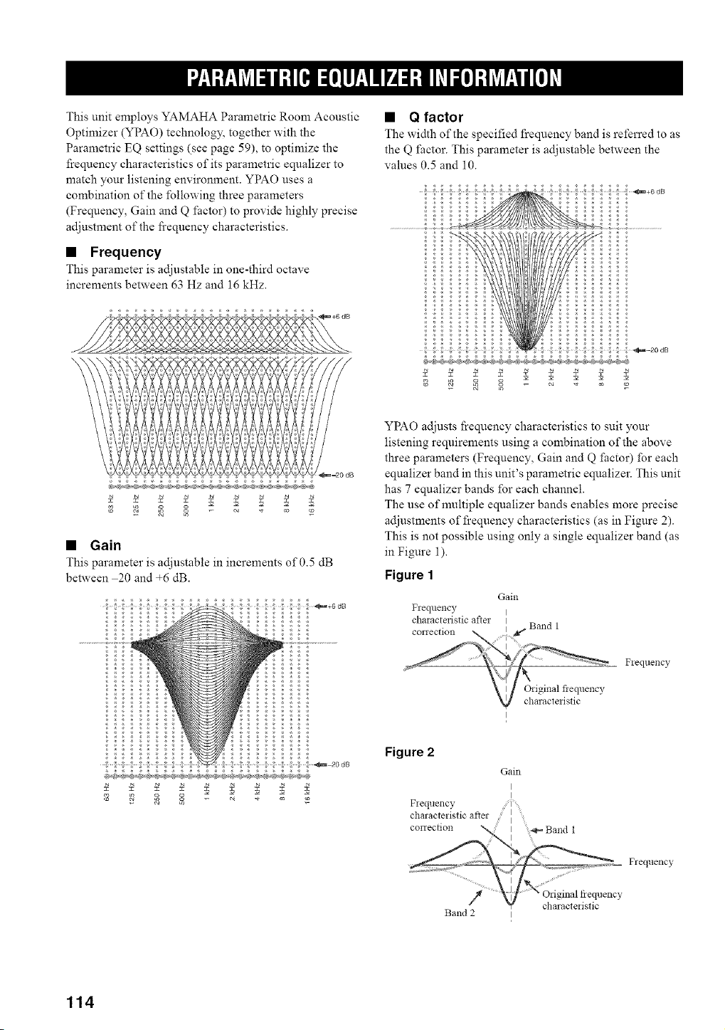
This unit employs YAMAHA Parametric Room Acoustic
Optimizer (YPAO) technology, together with the
Parametric EQ settings (see page 59), to optimize the
frequency characteristics of its parametric equalizer to
match your listening environment. YPAO uses a
combination of the following three parameters
(Frequency, Gain and Q factor) to provide highly precise
adjustment of the fi'equency characteristics.
• Frequency
This parameter is adjustable in one-third octave
increments between 63 Hz and 16 kHz.
• Q factor
The width of the specified frequency band is referred to as
the Q factor. This parameter is adjustable between the
values 0.5 and 10.
_+6 dB
c_ Le
• Gain
This parameter is adjustable in increments of 0.5 dB
between 20 and +6 dB.
YPAO adjusts frequency characteristics to suit your
listening requirements using a combination of the above
three parameters (Frequency, Gain and Q factor) for each
equalizer band in this unit's parametric equalizer. This unit
has 7 equalizer bands for each channel.
The use of nmltiple eqnalizer bands enables more precise
adjustments of frequency characteristics (as in Figure 2).
This is not possible using only a single equalizer band (as
in Figure 1).
Figure 1
Gain
Frequency I
characteristic after I
conection I _ Band 1
i
Fleqtlency
Original fiequency
charactedstic
I
Figure 2
Gain
I
I
F_equency
characteristic after I
correction _ I Band 1
,_,_ Frequency
.............. _ ;riginal fiequencv
Band 2 I
114
AUDIO SECTION
• Mininmni I_\IS Output Powm tbl Front, Centei, Surround
Smround back
20 Hz to 20 kHz 0.04% THD 8 (2 ..................................... 130 W
• Maximum Power (EIAJ)
[Asia, General, China and Korea models]
1 kHz, 10% THD, 8 _) .......................................................... 180 W
• Dynamic Power (IHF)
[US.A., Canada, Asia, Geneial, China, Korea and Australia
models]
8/6/4/2 _) ........................................................ 165/205/260/340 W
• DIN Standard Outpnt Power [UK. and Europe models]
1 kHz, 07% THD, 4 () ......................................................... 190 W
• Dynamic Headroom
[U.S.A., Canada, Asia, Genmal, China, Korea and Australia
models]
8 () ...................................................................................... 1 03 dB
• IEC Output Powe! [U.K. and Europe models]
1 kHz, 0.04% THD, 8 () ....................................................... 140 W
• Damping Factor (IHF)
20 Hz to 20 kHz, 8 _} ................................................... 140 or more
• Input Sensitivity/Input hnpedance
PHONO .................................................................. 3.5 mV'47 k!)
CD, etc .................................................................. 200 mVi47 k!_
MULTI CH INPUT ............................................... 200 mV/47 k!_
• Maximmn Input Signal
PHONO (1 kHz, 0 1% THD) .............................. 100 mV or more
CD, etc (1 kHz, 0.5% THD) .................................. 2.4 V or more
• Output LeveliOutpnt hnpedance
REC OUT ............................................................ 200 mVi1.2 k!_
PRE OUT ................................................................... 1.0 Vi500 _
SUBWOOFER ........................................................... 20 Vi500 _)
ZONE 2'ZONE 3 OUT ............................................. 1.0 Vi1.2 k!_
[U.S.A., Canada, Australia, U.K. and Europe models]
• Hea@hone Jack Rated Output/Impedance
CD, etc (1 kHz, 40 inV. 8 _}) ............................... 150 mVi100 _
• Frequency Response
CD to Front LiR ............................... 10 Hz to 100 kHz, +0_ 3 dB
• RIAA Equalization Deviation
PHONO (20 Hz to 20 kHz) .......................................... 0 ± 05 dB
• Total Harmonic Distoltion
PHONO to REC OUT
(20 Hz to 20 kHz, 1 V) ......................................... 002% or less
CD, etc to Front LiR
(20 Hz to 20 kHz, 65 W. 8 _}) ............................... 0.04% or less
• Signal to Noise Ratio (IHF-A Network)
PHONO (5 mV) to Front L/R
[USA., Canada, Asia, Genmal, China and Korea models]
.............................................................................. 86 dB or more
[Australia, U.K. and Europe models] ...................... 81 dB or more
CD, etc (250 mV) to Front LiR .......................................... 100 dB
• Residual Noise (IHF-A Network)
Front LiR ................................................................ 150 pV or less
• Channel Separation (1 kHzi10 kHz)
PHONO (sholtened) to Front L/R ............... 60 dBi55 dB or more
CD (5.1 k!) sholtened) to Front L'R ........... 60 dBi45 dB or more
• Tone Control Characteristics (Front DR)
BASS Boost'Cnt ....................................................... ±6 dBi50 Hz
BASS Tinhover Frequency .................................................. 350 Hz
TREBLE Boost/Cut ................................................ ±6 dBi20 kHz
TREBLE Turnover Frequency ............................................ 3.5 kHz
• Filtm Characteristics (fc 40/60/8090/100/110/120q60/200 Hz)
H.PF (Front, Center, Surromid, Surrmmd back) ........... 12 dB'oct.
LPF (Subwoof_r) ......................................................... 24 dBioct.
VIDEO SECTION
• Video Signal Type (Wall Paper)
[Asia, China, Austialia, U.K. and Emope models] ................ PAL
[U.S.A., Canada, General and Korea models] .................... NTSC
• Video Signal Type (Video Conversion)
[Asia, General, China, Australia, UK. and Europe models]
.............................................................................................. PAL
[Other models] .................................................................... NTSC
• Signal Level
Composite ................................................................. 1 Vp-pi75 _}
S-video ............................ 1 Vp-pi75 _} (Y), 0.286 Vp-pi75 _} (C)
Component ................... 1 Vp-pi75 _ (Y), 07 Vp-pi75 _) (PbiPr)
• Maximum Inpnt Level .......................................... 1.5 Vp-p or more
• Simml to Noise Ratio ................................................ 60 dB or more
• Frequency Response (MONITOR OUT)
Composite, S-video .................................. 5 Hz to 10 MHz, 3 dB
Component ............................................... 5 Hz to 60 MHz, 3 dB
FM SECTION
• Tuning Range
[U.S.A. and Canada models] ........................... 87.5 to 107.9 MHz
[Asia and General models] ........ 875/8750 to 108.0/10800 MHz
[Other models] ............................................ 8750 to 10800 MHz
• Usable Sensitivi_, (IHF) ....................................... 1.0 pV (11.2 dBt)
• SelectiviB, ................................................................................ 70 dB
• Signal to Noise Ratio (IHF)
MonoiStereo .............................................................. 76 dBi70 dB
HD [U.S.A. model only] ...................................................... 80 dB
• Harmonic Distoltion (1 kHz)
MonoiStereo ................................................................ 02%'03%
HD [U.S.A. model only] ..................................................... 003%
• Stereo Separation (1 kHz)
Stereo ..................................................................................... 42 dB
HD [U.S.A. model only] ...................................................... 70 dB
• Frequency Response
Stmeo .............................................. 20 Hz to 15 kHz, +0.5, 2 dB
HD [U.S.A. model only] ................ 20 Hz to 18 kHz, ÷0.5, 3 dB
• Antenna Input (unbalanced) ..................................................... 75 _}
115
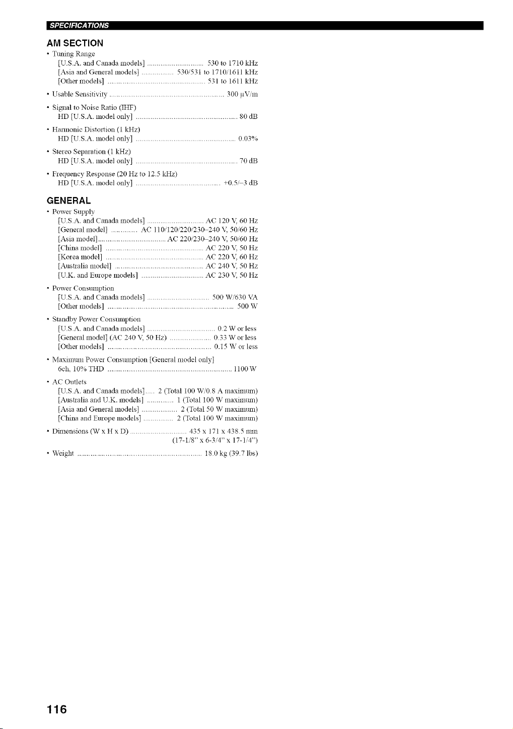
AM SECTION
• Tuning Range
[U S.A. and Canada models] .............................. 530 to 1710 kHz
[Asia and General models] ................. 530/531 to 1710/1611 kHz
[Other models] .................................................... 531 to 1611 kHz
• Usable Sensitivi_, ............................................................. 300 pV,'m
• Signal toNoise Ratio (IHF)
HD [USA. model only] ...................................................... 80 dB
• Harmonic Distortion (t kHz)
HD [USA. model only] ..................................................... 0.03%
• Stereo Separation (t kHz)
HD [USA. model only] ...................................................... 70 dB
• Frequency Response (20 Hz to 12.5 kHz)
HD [USA. model only] ............................................. +05_3 dB
GENERAL
• Power Supply
[USA. and Canada models] .............................. AC 120 V 60 Hz
[General model] .............. AC 110/120/220/230240 \; 50/60 Hz
[Asia model] .................................... AC 220/230 240 \; 50/60 Hz
[China model] .................................................... AC 220 \\ 50 Hz
[Korea model] .................................................... AC 220 \\ 60 Hz
[Austlalia model] ............................................... AC 240 \_ 50 Hz
[UK. and Europe models] ................................. AC 230 \i 50 Hz
• Power Consumption
[US.A. and Canada models] ................................. 500 W/630 \A
[Otha models] ................................................................... 500 W
• Standby Power Consmnption
[USA. and Canada models] .................................... 02 W or less
[General model] (AC 240 \\ 50 Hz) ...................... 033 W or less
[Other models] ....................................................... 0.15 W or less
• Maximmn Power Conslunption [General model only]
6ch, 10% THD .................................................................. II00W
• AC Outlets
[U.S A. and Canada models]... 2 (Total 100 W/08 A maximum)
[Austlalia and U.K. models] .............. 1 (Total 100 W maximum)
[Asia and General models] ................... 2 (Total 50 W maximum)
[China and Europe models] ................ 2 (Total 100 W maximum)
• Dimensions (W x H x D) .............................. 435 x 171 x 4385 rain
(17-1/8" x 6-3/4" x 17-1/4")
• WeigN .................................................................. 180kg (397 lbs)
116
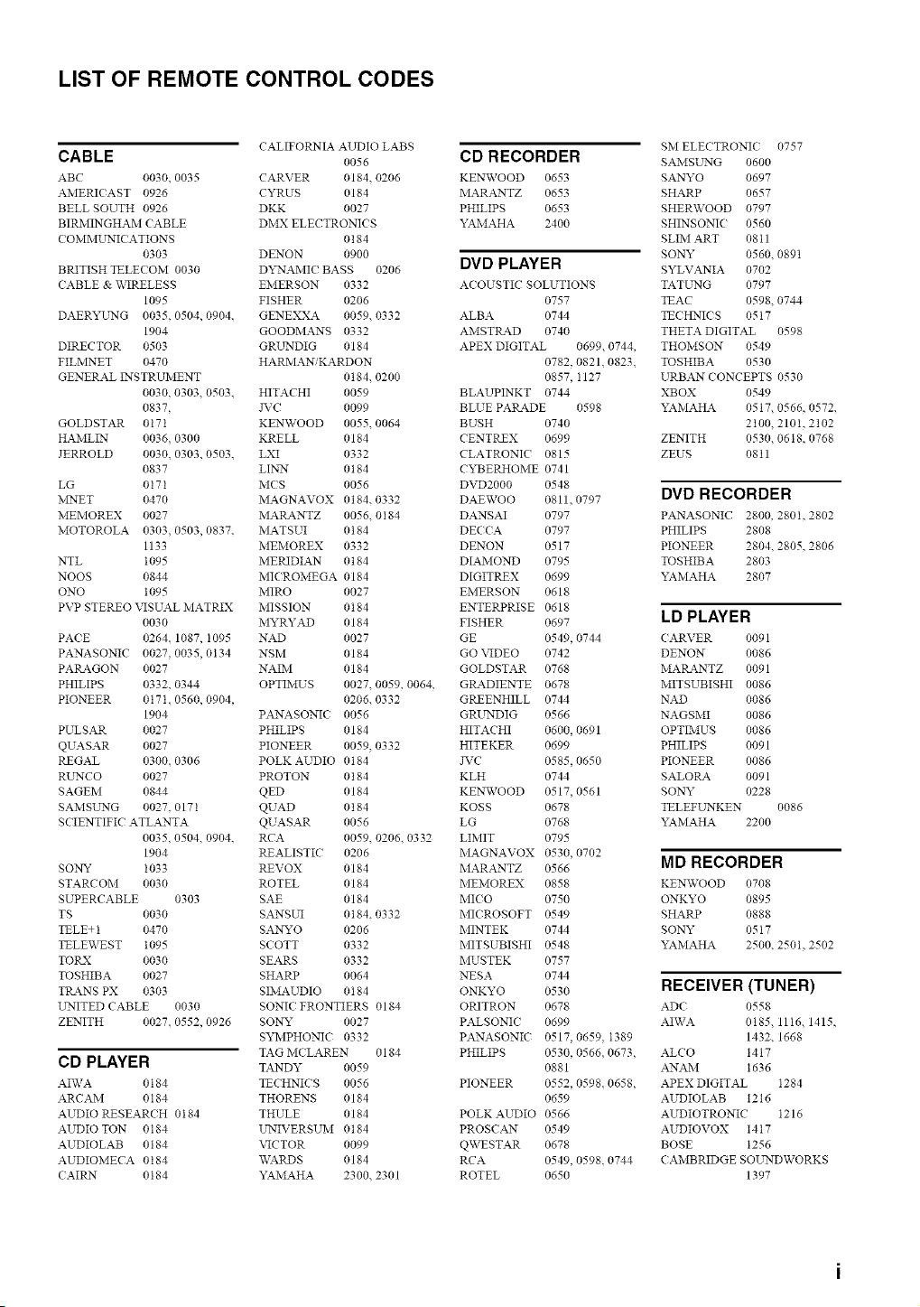
LIST OF REMOTE CONTROL CODES
CALIFORNIA AUDIO LABS
CABLE 0056
ABC 0030. 0035 CARVER 0184 0206
AMERIC AST 0926 CYRUS 0184
BELL SOUTH 0926 DKK 0027
BIRMINGHAM CABLE DMX ELECTRONICS
C OMML _rNIC ATIONS 0184
0303 DENON 0900
BRITISH TELECOM 0030 D'x _'NAMIC BASS 0206
CABLE & _\_RELESS EiVIERSON 0332
1095 FISHER 0206
DAERYUNG 0035. 0504, 0904. GENEXXA 0059. 0332
1904 GOODMANS 0332
DIRECTOR 0503 GRLLNDIG 0184
FILMNET 0470 HARMANiKARDON
GENERAL INSTRUMENT 0184, 0200
0030, 0303. 0503. HITACHI 0059
0837, JVC 0099
GOLDSTAR 0171 KENWOOD 0055. 0064
HAMLIN 0036, 0300 KRELL 0184
JERROLD 0030. 0303, 0503. LXI 0332
0837 LIN_ r 0184
LG 0171 MCS 0056
MNET 0470 MAGNAVOX 0184.0332
MEMOREX 0027 MARANTZ 0056, 0184
MOTOROLA 0303. 0503, 0837. MATSUI 0184
1133 MEMOREX 0332
NTL I095 MERIDIAN 0t84
NODS 0844 MICROMEGA 0184
ONO 1095 MIRO 0027
PVP STEREO VISUAL MATRIX MISSION 0184
0030 MYRYAD 0184
PACE 0264. 1087, I095 NAD 0027
PANASONIC 0027. 0035, 0134 NSM 0184
PARAGON 0027 NAIM 0184
PHILIPS 0332. 0344 OPTIMUS 0027. 0059, 0064,
PIONEER 017L 0560, 0904, 0206. 0332
1904 PANASONIC 0056
PULSAR 0027 PHILIPS 0184
QUASAR 0027 PIONEER 0059, 0332
REGAL 0300.0306 POLK AUDIO 0184
RL _rNCO 0027 PROTON 0184
SAGEM 0844 QED 0184
SAMSL _rNG 0027. 0171 QUAD 0184
SCIENTIFIC ATLANTA QUASAR 0056
0035, 0504. 0904. RCA 0059, 0206. 0332
1904 REALISTIC 0206
SONY I033 REVOX 0184
STARCOM 0030 ROTEL 0184
SUPERCABLE 0303 SAE 0184
TS 0030 SANSUI 0184. 0332
TELE+ 1 0470 SANYO 0206
TELEWEST 1095 SCOTT 0332
TO P.-X 0030 SEARS 0332
TOSHIBA 0027 SHARP 0064
TP_kN S PX 0303 SIMAUDIO 0184
UNITED CABLE 0030 SONIC? FRONTIERS 0184
ZENITH 0027. 0552, 0926 SONY 0027
SYMPHONIC 0332
TAG MC LAREN 0184
CD PLAYER TARDY 0059
AIWA 0t84 TECHNICS 0056
ARCAM 0184 THORENS 0184
AUDIO RESEARCH 0184 THULE 0184
AUDIOTON 0t84 UNIVERSUM 0t84
AUDIOLAB 0184 VICTOR 0099
AUDIOMECA 0t84 WARDS 0184
CAIRN 0184 YAMAHA 2300. 2301
CD RECORDER
KENWOOD 0653
MARANTZ 0653
PHILIPS 0653
YAMAHA 2400
DVD PLAYER
ACOUSTIC SOLUTIONS
0757
ALBA 0744
AMSTI_.D 0740
APEX DIGITAL 0699.0744,
0782, 0821. 0823.
0857, I127
BLAUPINKT 0744
BLUE PARADE 0598
BUSH 0740
CENTREX 0699
CLATRONIC 0815
CYBERHOME 0741
DVD2000 0548
DAEWOO 0811, 0797
DANSAI 0797
DECCA 0797
DENDN 0517
DIAMOND 0795
DIGITREX 0699
EMERSON 0618
ENTERPRISE 0618
FISHER 0697
GE 0549, 0744
GO VIDEO 0742
GOLDSTAR 0768
GP_DIENTE 0678
GREENHILL 0744
GRL _rNDIG 0566
HITACHI 0600, 0691
HITEKER 0699
J_TC 0585, 0650
KLH 0744
KENWOOD 0517, 0561
KOSS 0678
LG 0768
LIMIT 0795
MAGNAVOX 0530, 0702
MARANTZ 0566
MEMOREX 0858
MICO 0750
MICROSOFT 0549
MINTEK 0744
MITSUBISHI 0548
MUSTEK 0757
NESA 0744
ONKYO 0530
ORITRON 0678
PALSONIC 0699
PANASONIC 0517, 0659. I389
PHILIPS 0530, 0566. 0673,
0881
PIONEER 0552, 0598. 0658,
0659
POLK AUDIO 0566
PROSCAN 0549
QWESTAR 0678
RCA 0549, 0598. 0744
ROTEL 0650
SM ELECTRONIC 0757
SAMSL _rNG 0600
SANYO 0697
SHARP 0657
SHERWOOD 0797
SHINSONIC 0560
SLIM ART 0811
SONY 0560. 0891
SYLVANIA 0702
TATUNG 0797
TEAC 0598. 0744
TECHNICS 05t7
THETA DIGITAL 0598
THOMSON 0549
TOSHIBA 0530
URBAN CONCEPTS 0530
XBOX 0549
YAMAHA 0517. 0566, 0572.
2t00, 2101, 2102
ZENITH 0530. 0618, 0768
ZEUS 0811
DVD RECORDER
PANASONIC 2800, 280I, 2802
PHILIPS 2808
PIONEER 2804. 2805, 2806
TOSHIBA 2803
YAMAHA 2807
LD PLAYER
CARVER 0091
DENON 0086
MARANTZ 0091
MITSUBISHI 0086
NAD 0086
NAGSMI 0086
OPTIMUS 0086
PHILIPS 0091
PIONEER 0086
SALORA 0091
SONY 0228
TELEFUNKEN 0086
YAMAHA 2200
MD RECORDER
KENWOOD 0708
ONKYO 0895
SHARP 0888
SONY 0517
YAMAHA 2500. 250I, 2502
RECEIVER (TUNER)
ADC 0558
AIWA 0185, 1116. 1415,
1432. 1668
ALCO 1417
ANAM 1636
APEX DIGITAL 1284
AUDIOLAB 1216
AUDIOTRONIC I216
AUDIOVOX t4t7
BOSE 1256
CAMBRIDGE SOLLNDWORKS
1397
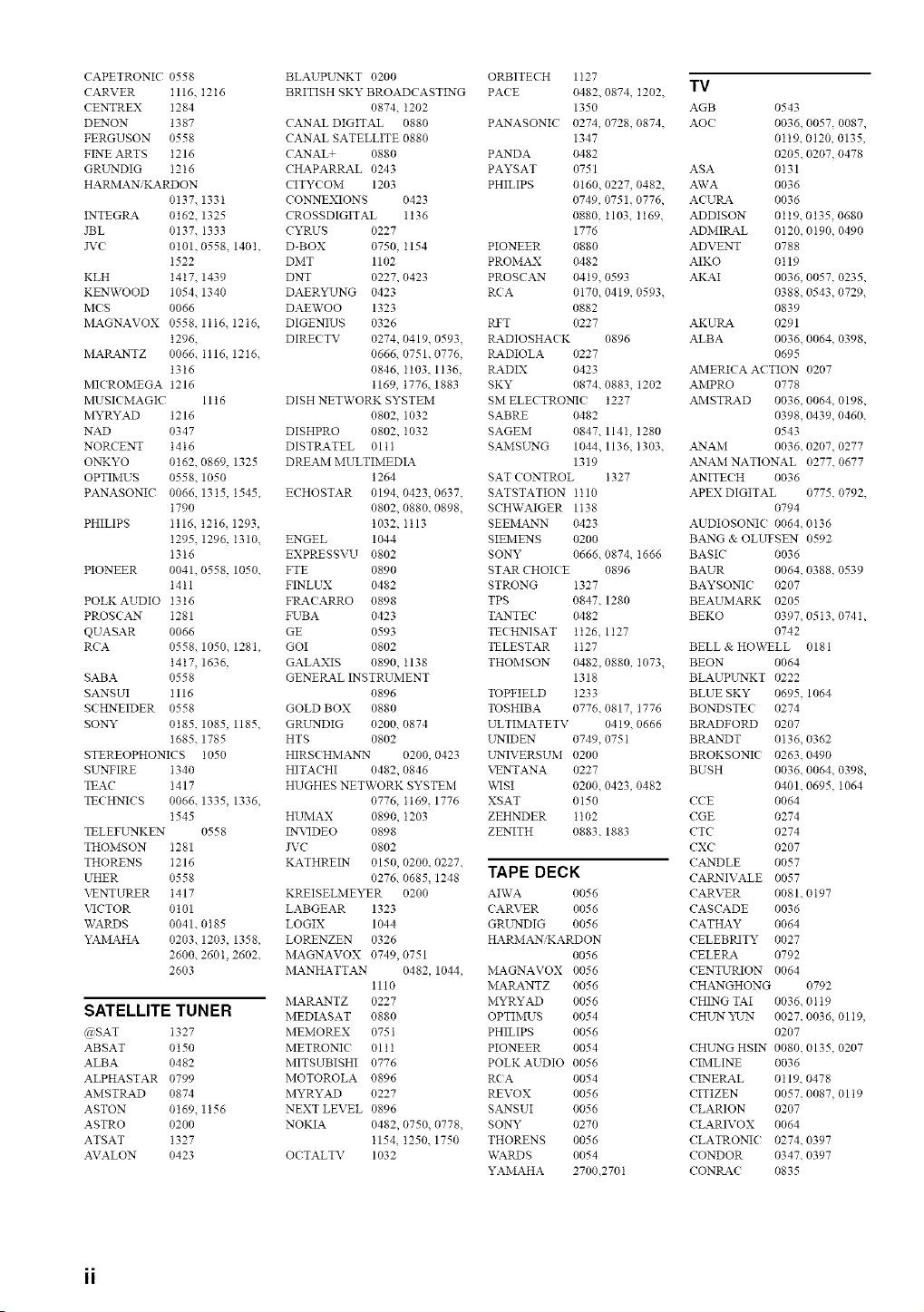
CAPETRONIC 0558
CARVER I116, t2t6
CENTREX I284
DENON 1387
FERGUSON 0558
FINE ARTS t216
GRLLNDIG I216
HARMANiKARDON
0t37, 133I
INTEG P_4 0162. 1325
JBL 0137. I333
JV( 0101. 0558. 1401,
t522
KLH t4t7. 1439
KENWOOD 1054. 1340
MCS 0066
MAGNAVOX 055K 1ti6. 12t6,
t296.
MARANTZ 0066. II16. 1216.
1316
MICROMEGA 1216
MUSIC MAGIC 11 t 6
MYRYAD 1216
NAD 0347
NORCENT t4 t6
ONKYO 0162. 0869, 1325
OPTIMUS 0558. 1050
PANASONIC 0066, 1315, 1545,
t790
PHILIPS Ii16. 1216, 1293,
t295. 1296, I310.
1316
PIONEER 0041. 0558, 1050,
t4tl
POLK AUDIO I3t6
PROSCAN I281
QUASAR 0066
RCA 0558. 1050, 1281,
t4t7, 1636,
SABA 0558
SANSUI I 116
S(HNEIDER 0558
SONY 0t85. 1085, 1185,
1685. 1785
STEREOPHONICS 1050
SLLNFIRE 1340
TEAC I417
TECHNICS 0066. 1335, 1336,
1545
TELEPLLNKEN 0558
THOMSON I281
THORENS I216
UHER 0558
VENTURER t417
VICTOR 0101
WARDS 0041. 0185
YAMAHA 0203. 1203, 1358,
2600. 260t, 2602.
2603
SATELLITE TUNER
@SAT I327
ABSAT 0t50
ALBA 0482
ALPHASTAR 0799
AMSTRAD 0874
ASTON 0169, 1156
ASTRO 0200
ATSAT 1327
AVALON 0423
BLAUPUNKT 0200
BRITISH SKY BROADCASTING
0874. I202
CANAL DIGITAL 0880
CANAL SATELLITE 0880
CANAL+ 0880
CHAPARRAL 0243
CITY(OM 1203
CONLNEXIONS 0423
CROSSDIGITAL 1136
CYRUS 0227
D-BOX 0750, 1154
DMT 1102
DNT 0227, 0423
DAERYUNG 0423
DAEWOO 1323
DIGENIUS 0326
DIRE(TV 0274, 0419, 0593,
0666. 0751. 0776,
0846. I103. 1136.
t169, t776, 1883
DISH NETWORK SYSTEM
0802. I032
DISHPRO 0802, I032
DISTRATEL 01 t I
DREAM MULTIMEDIA
1264
ECHOSTAR 0194. 0423, 0637.
0802, 0880, 0898,
1032, Ii13
ENGEL 1044
EXPRESSVU 0802
FTE 0890
FINLUX 0482
FtL4C ARRO 0898
FUBA 0423
GE 0593
GOI 0802
GALAXIS 0890, 1138
GENERAL INSTRUMENT
0896
GOLD BOX 0880
GRLLNDIG 0200. 0874
HTS 0802
HIRSCHMANN 0200, 0423
HITACHI 0482, 0846
HUGHES NETWORK SYSTEM
0776. I169. 1776
HUMAX 0890, I203
INVIDEO 0898
JVC 0802
KATHREIN 0150, 0200, 0227,
0276. 0685, 1248
KREISELMEYER 0200
LABGEAR 1323
LOGIX 1044
LORENZEN 0326
MAGNAVOX 0749,0751
MANHATTAN 0482, 1044,
1110
MARANTZ 0227
MEDIASAT 0880
MEMOREX 075 t
METRONI( 01 t I
MITSUBISHI 0776
MOTOROLA 0896
MYRYAD 0227
NEXT LEVEL 0896
NOKIA 0482, 0750, 0778.
1154, 1250. 1750
O(TALTV 1032
ORBITECH 1127
PA(E 0482. 0874, I202.
1350
PANASONIC 0274, 0728, 0874.
1347
PANDA 0482
PAYSAT 0751
PHILIPS 0160, 0227, 0482,
0749, 0751. 0776,
0880, I103. I169.
1776
PIONEER 0880
PROMAX 0482
PROSCAN 04t9. 0593
R(A 0170. 0419, 0593.
0882
RFT 0227
tL4DIOSHAC K 0896
RADIOLA 0227
P_4.DIX 0423
SKY 0874. 0883, 1202
SM ELECTRO_( t227
SABRE 0482
SAGEM 0847. 114I, 1280
SAMSLLNG 1044. 1136, I303.
1319
SAT ( ONTROL 1327
SATSTATION II10
SCH_VAIGER 1t38
SEEMANN 0423
SIEiVlENS 0200
SONY 0666, 0874, 1666
STAR CHOICE 0896
STRONG 1327
TPS 0847. 1280
TANTEC 0482
TECHNISAT 1t26. 1127
TELESTAR t 127
THOMSON 0482, 0880, I073.
1318
TOPFIELD 1233
TOSHIBA 0776, 0817, 1776
ULTIMATETV 0419. 0666
LLNIDEN 0749, 075 I
LLNIVERSUM 0200
VENTANA 0227
\:_qSI 0200. 0423, 0482
XSAT 0150
ZEHNDER 1102
ZENITH 0883. 1883
TAPE DECK
AIWA 0056
CARVER 0056
GRUNDIG 0056
HARiVIANiKARDON
0056
MAGNAVOX 0056
MAILa.NTZ 0056
MYRYAD 0056
OPTIMUS 0054
PHILIPS 0056
PIONEER 0054
POLK AUDIO 0056
R(A 0054
REVOX 0056
SANSUI 0056
SONY 0270
THORENS 0056
WARDS 0054
YAMAHA 2700.2701
TV
AGB 0543
AOC 0036. 0057, 0087,
0119. 0120, 0135,
0205. 0207, 0478
ASA 0131
AWA 0036
ACURA 0036
ADDISON 01t9.0135,0680
ADMIt_L 0120. 0190, 0490
ADVENT 0788
AIKO 0119
AKAI 0036. 0057, 0235,
0388. 0543, 0729.
0839
AKUtLa. 0291
ALBA 0036. 0064, 0398,
0695
AMERICA ACTION 0207
AMPRO 0778
AMSTRAD 0036. 0064, 0198,
0398. 0439, 0460.
0543
ANAM 0036. 0207, 0277
ANAM NATIONAL 0277. 0677
ANITEC H 0036
APEX DIGITAL 0775. 0792.
0794
AUDIOSONIC 0064. 0136
BANG & OLUFSEN 0592
BASIC 0036
BAUR 0064. 0388, 0539
BAYSONI( 0207
BEAUMARK 0205
BEKO 0397. 0513, 0741,
0742
BELL & HO\_'_LL 0181
BEON 0064
BLAUPUNKT 0222
BLUE SKY 0695. 1064
BONDSTEC 0274
BRADFORD 0207
BRANDT 0136. 0362
BROKSONK 0263. 0490
BUSH 0036. 0064, 0398,
0401. 0695, I064
CCE 0064
CGE 0274
CTC 0274
CX( 0207
CANDLE 0057
CARNIVALE 0057
CARVER 0081.0t97
CASCADE 0036
CATHAY 0064
CELEBRITY 0027
CELEP_k 0792
CENTURION 0064
CHANGHONG 0792
CHING TAI 0036. 01 t 9
CHLLN YULN 0027. 0036, 01 t9,
0207
CHLLNG HSIN 0080. 0135, 0207
CIMLINE 0036
CINERAL 0119, 0478
CITIZEN 0057, 0087, 01 t9
CLARION 0207
CLARIVOX 0064
CLATRONIC 0274. 0397
CONDOR 0347. 0397
CONRAC 0835
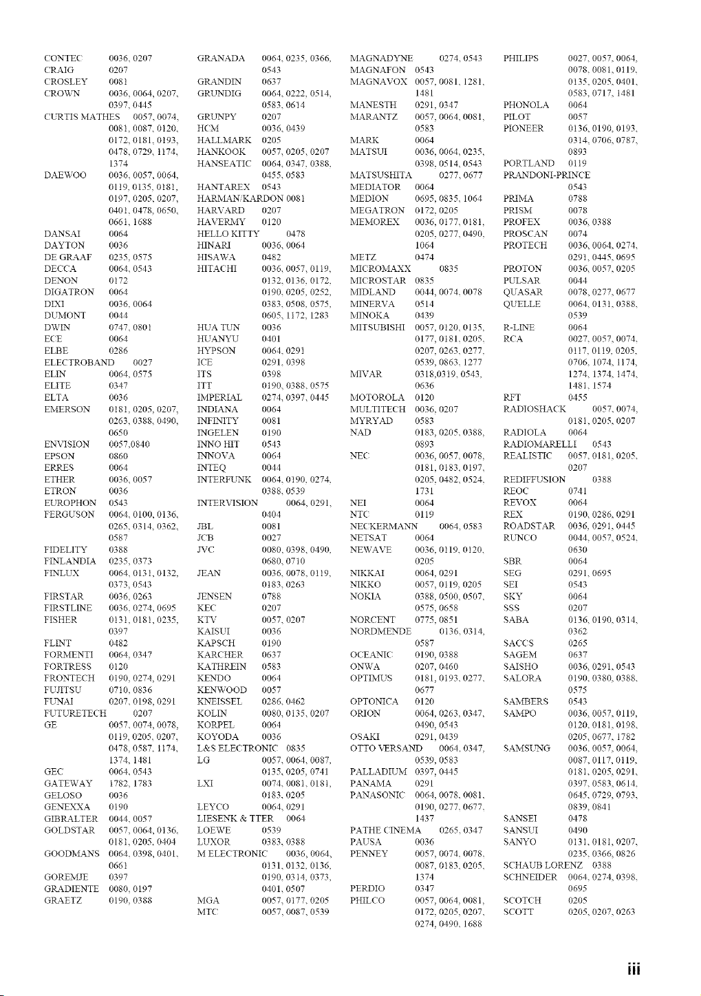
cONTEC0036.0207
CRAIG 0207
CROSLEY0081
CROWN0036,0064,0207.
0397,0445
CURTISMATHES0057.0074,
008I,0087.0120.
0172,0181,0193.
0478,0729,1174.
1374
DAEWOO0036.0057,0064,
0119,0135.018I,
0197,0205,0207,
040t,0478,0650.
066t,I688
DANSAI 0064
DAYTON0036
DEGRAAF0235,0575
DECCA 0064.0543
DENON 0172
DIGATRON 0064
DIXI 0036, 0064
DUMONT 0044
DWIN 0747. 080 I
ECE 0064
ELBE 0286
ELECTROBAND 0027
ELIN 0064. 0575
ELITE 0347
ELTA 0036
ElVIERSON 0181, 0205, 0207,
0263, 0388. 0490.
0650
ENVISION 0057.0840
EPSON 0860
ERRES 0064
ETHER 0036. 0057
ETRON 0036
EUROPHON 0543
FERGUSON 0064. 0100, 0136.
0265. 0314. 0362.
0587
FIDELITY 0388
FINLANDIA 0235. 0373
FINLUX 0064, 0131, 0132,
0373, 0543
FIRSTAR 0036, 0263
FIRSTLINE 0036, 0274, 0695
FISHER 0131, 018I, 0235,
0397
FLINT 0482
FORMENTI 0064, 0347
FORTRESS 0120
FRONTECH 0t90, 0274, 0291
FU;2T SU 0710, 0836
FLLNAI 0207, 0198, 0291
FUTURETECH 0207
OE 0057. 0074, 0078,
01 t9, 0205, 0207.
0478, 0587, 1174.
1374, I481
GEC 0064. 0543
GATEWAY 1782 1783
GELOSO 0036
GENEXXA 0190
GIBRALTER 0044. 0057
GOLDSTAR 0057, 0064, 0136.
018t, 0205. 0404
GOODMANS 0064.0398,0401.
066t
GOREMJE 0397
GRADIENTE 0080, 0197
GRAETZ 0190. 0388
GP_4NADA 0064. 0235, 0366,
0543
GRANDIN 0637
GRLLNDIG 0064. 0222, 0514,
0583. 0614
GRL_PY 0207
HCM 0036. 0439
HALLMARK 0205
HANKOOK 0057, 0205. 0207
HANSEATK _ 0064.0347, 0388,
0455. 0583
HANTAREX 0543
HARMAN, KARDON 008 t
HARVARD 0207
HAVERMY 0120
HELLO KITTY 0478
HINAR1 0036, 0064
HISAWA 0482
HITACHI 0036. 0057, 01 I9,
0132. 0136, 0172,
0190. 0205, 0252,
0383. 0508, 0575,
0605. 1172. 1283
HUA TLLN 0036
HUANYU 0401
HYPSON 0064 0291
ICE 0291. 0398
ITS 0398
ITT 0190 0388.0575
IMPERIAL 0274 0397. 0445
INDIANA 0064
INFINITY 0081
INOELEN 0190
INNO HIT 0543
INNOVA 0064
INTEQ 0044
INTERFLLNK 0064. 0190, 0274,
0388. 0539
INTERVISION 0064, 0291.
0404
JBL 0081
JCB 0027
JVC 0080, 0398. 0490,
0680. 0710
JEAN 0036. 0078, 0119,
0t 83, 0263
JENSEN 0788
KEC 0207
KTV 0057. 0207
KAISUI 0036
KAPSCH 0190
KARC HER 0637
KATHREIN 0583
KENDO 0064
KENWOOD 0057
KNEISSEL 0286. 0462
KOLIN 0080, 0135. 0207
KORPEL 0064
KOYODA 0036
L&S ELECTRONIC 0835
LG 0057. 0064, 0087,
0t35, 0205, 0741
LXI 0074. 008I, 018t,
0183. 0205
LEYCO 0064. 0291
LIESENK & TTER 0064
LOEWE 0539
LUXOR 0383. 0388
M ELECTRONK' 0036, 0064.
0131. 0132, 0136,
0190. 0314, 0373,
0401. 0507
MGA 0057. 0177, 0205
MTC 0057, 0087. 0539
MAGNADYNE 0274, 0543
MAGNAFON 0543
MAGNAVOX 0057, 0081_ 1281,
1481
MANESTH 0291, 0347
MARANTZ 0057, 0064, 0081,
0583
MARK 0064
MATSUI 0036, 0064, 0235,
0398. 0514. 0543
MATSUSHITA 0277. 0677
MEDIATOR 0064
MEDION 0695, 0835, 1064
MEGATRON 0172, 0205
MEMOREX 0036, 0177, 0181,
0205, 0277, 0490.
1064
METZ 0474
MIC ROMAXX 0835
MIC ROSTAR 0835
MIDLAND 0044, 0074. 0078
MINERVA 0514
MINOKA 0439
MITSUBISHI 0057, 0120, 0135,
0177, 0t81. 0205.
0207, 0263. 0277,
0539, 0863. 1277
MIVAR 0318,03 t9, 0543,
0636
MOTOROLA 0120
MULTITECH 0036, 0207
MYRYAD 0583
NAD 0183, 0205, 0388,
0893
NEC 0036, 0057, 0078,
0181, 0183. 0197.
0205, 0482, 0524.
1731
NEI 0064
NTC 0119
NECKERMANN 0064. 0583
NETSAT 0064
NEWAVE 0036, 0119, 0120,
0205
NIKKAI 0064, 0291
NIKKO 0057, 0119 0205
NOKIA 0388, 0500 0507,
0575, 0658
NORCENT 0775, 0851
NORDMENDE 0t36. 0314,
0587
OCEANIC 0190, 0388
ONWA 0207, 0460
OPTIMUS 0181, 0t93. 0277.
0677
OPTONICA 0120
ORION 0064, 0263, 0347,
0490, 0543
OSAKI 0291, 0439
OTTO VERSAND 0064, 0347,
0539, 0583
PALLADIUM 0397, 0445
PANAMA 0291
PANASONK 0064, 0078. 008I.
0190, 0277. 0677.
1437
PATHE CINEMA 0265. 0347
PAUSA 0036
PENNEY 0057. 0074 0078,
0087 0183. 0205.
1374
PERDIO 0347
PHILCO 0057, 0064, 008 I,
0172 0205 0207.
0274, 0490. 1688
PHILIPS 0027. 0057, 0064,
0078. 0081, 0119.
0t35, 0205, 0401.
0583. 0717, 1481
PHONOLA 0064
PILOT 0057
PIONEER 0136. 0190, 0193.
0314, 0706, 0787.
0893
PORTLAND 0119
PRANDONI-PRINCE
0543
PRIMA 0788
PRISM 0078
PROFEX 0036, 0388
PROSCAN 0074
PROTECH 0036, 0064, 0274.
029t. 0445, 0695
PROTON 0036, 0057, 0205
PULSAR 0044
QUASAR 0078, 0277, 0677
QUELLE 0064, 013 I, 0388,
0539
R-LINE 0064
RCA 0027. 0057, 0074.
0t17, 0119, 0205,
0706. 1074, 1174,
1274. 1374, 1474.
1481. 1574
RFT 0455
RADIOSHACK 0057. 0074.
0t81, 0205, 0207
RADIOLA 0064
RADIOMARELLI 0543
REALISTIC 0057, 018I, 0205,
0207
REDIFFUSION 0388
REOC 0741
REVOX 0064
REX 0190. 0286, 0291
ROADSTAR 0036, 0291, 0445
RL'NC O 0044, 0057, 0524.
0630
SBR 0064
SEG 029 I. 0695
SEI 0543
SKY 0064
SSS 0207
SABA 0136. 0190, 0314.
0362
SACCS 0265
SAGEM 0637
SAISHO 0036 0291, 0543
SALORA 0190. 0380, 0388.
0575
SAMBERS 0543
SAMPO 0036 0057, 0119,
0120. 018t, 0t98.
0205. 0677, 1782
SAMSLLNG 0036. 0057, 0064.
0087, 0117, 0t 19,
0t8I. 0205, 0291,
0397. 0583, 0614.
0645. 0729, 0793.
0839, 0841
SANSEI 0478
SANSUI 0490
SANYO 0t3 t. 0181, 0207.
0235. 0366, 0826
SCHAUB LORENZ 0388
SCHNEIDER 0064. 0274, 0398.
0695
SCOTCH 0205
SCOTT 0205. 0207, 0263
III
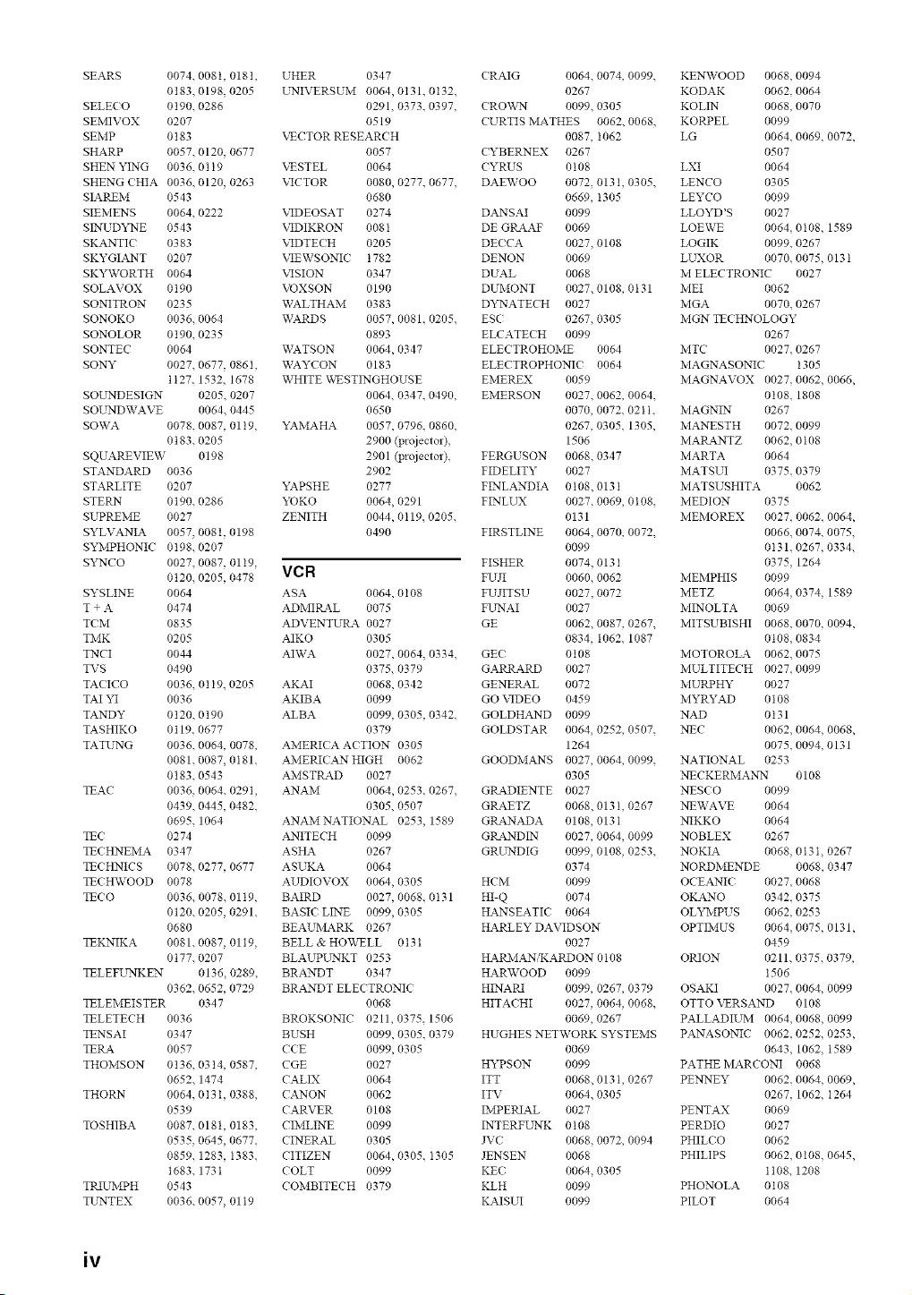
SEARS 0074. 008t, 018I,
0183, 0198, 0205
SELE< O 0190. 0286
SEMIVOX 0207
SEMP 0183
SHARP 0057. 0120, 0677
SHEN YING 0036.01t9
SHENG <HIA 0036. 0120, 0263
SIAREM 0543
SIEMENS 0064. 0222
SINUD22qE 0543
SKANTI< 0383
SKYGIANT 0207
SKYWORTH 0064
SOLAVOX 0t90
SONITRON 0235
SONOKO 0036, 0064
SONOLOR 0190. 0235
SONTEC 0064
SONY 0027. 0677, 0861,
ti27. 1532, 1678
SOL%NDESIGN 0205. 0207
SOLtNDWAVE 0064. 0445
SOWA 0078. 0087, 0119,
0t83. 0205
SQUAREVIEW 0198
STANDARD 0036
STARLITE 0207
STERN 0190. 0286
SUPREME 0027
SYLVANIA 0057, 0081, 0198
SY]V[PHONIC 0198. 0207
SN2"7CO 0027. 0087, 0119,
0120, 0205, 0478
SYSLINE 0064
T + A 0474
TOM 0835
TMK 0205
TNCI 0044
TVS 0490
TA< ICO 0036. 0119. 0205
TAI YI 0036
TANDY 0120. 0 t90
TASHIKO 0119. 0677
TATU'NG 0036. 0064, 0078,
0081. 0087, 0181.
0183. 0543
TEAC 0036, 0064. 029t,
0439. 0445, 0482.
0695, 1064
TEC 0274
TEC HNEMA 0347
TECHNICS 0078. 0277, 0677
TEC HWOOD 0078
TECO 0036. 0078.0119,
0120. 0205, 0291.
0680
TEKNIKA 0081. 0087, 0119,
0t77. 0207
TELEFL%NKEN 0136, 0289.
0362. 0652, 0729
TELEMEISTER 0347
TELETECH 0036
TENSAI 0347
TERA 0057
THOMSON 0136. 0314, 0587,
0652. 1474
THORN 0064, 013 I, 0388,
0539
TOSHIBA 0087. 0181, 0183,
0535, 0645, 0677.
0859. 1283, I383.
1683. 173I
TRIUMPH 0543
TL_'NTEX 0036. 0057, 01 t9
UHER 0347
L'NIVERSUM 0064,0131.0t32.
0291, 0373. 0397,
0519
VECTOR RESEARCH
0057
XNSTEL 0064
VICTOR 0080, 0277. 0677.
0680
VIDEOSAT 0274
X2DIKRON 008 t
VIDTEC H 0205
VIEWSONI< 1782
VISION 0347
VOXSON 0190
WALTHAM 0383
WARDS 0057, 0081. 0205.
0893
WATSON 0064, 0347
WAYCON 0183
WHITE \K_STINGHOUSE
0064. 0347. 0490,
0650
YAMAHA 0057, 0796. 0860.
2900 (projector).
2901 (projector).
2902
YAPSHE 0277
YOKO 0064, 0291
ZENITH 0044, 0119. 0205.
0490
VCR
ASA 0064, 0108
ADMIRAL 0075
ADVENTUtL4 0027
AIKO 0305
AIWA 0027, 0064, 0334.
0375. 0379
AKAI 0068, 0342
AKIBA 0099
ALBA 0099, 0305, 0342.
0379
AMERICA ACTION 0305
AMERICAN HIGH 0062
AMSTIL&D 0027
ANAM 0064, 0253. 0267.
0305. 0507
ANAMNATIONAL 0253, 1589
ANITECH 0099
ASHA 0267
ASUKA 0064
AUDIOVOX 0064, 0305
BAIRD 0027, 0068. 0 t 31
BASIC LINE 0099, 0305
BEAUMARK 0267
BELL & HO_\T LL 0 t 3 t
BLAUPUNKT 0253
BRANDT 0347
BRANDT ELECTRONIC
0068
BROKSONIC 0211, 0375. 1506
BUSH 0099, 0305. 0379
CCE 0099, 0305
CGE 0027
CALIX 0064
CANON 0062
CARVER 0108
CIMLINE 0099
CINERAL 0305
CITIZEN 0064, 0305. I305
COLT 0099
COMBITECH 0379
CRAIG 0064. 0074, 0099.
0267
< RO\K,kN 0099. 0305
CURTIS MATHES 0062. 0068,
0087, I062
CYBERNEX 0267
CYRUS 0108
DAEWOO 0072, 013 I, 0305.
0669, 1305
DANSAI 0099
DE GRAAF 0069
DE<CA 0027, 0108
DENON 0069
DUAL 0068
DUMONT 0027. 0108, 0131
D22"_ATECH 0027
ESC 0267, 0305
ELCATECH 0099
ELECTROHOME 0064
ELECTROPHONI< 0064
EMEREX 0059
EMERSON 0027. 0062, 0064.
0070, 0072. 021 t.
0267, 0305. 1305,
1506
FERGUSON 0068. 0347
FIDELITY 0027
FINLANDIA 0108.013 I
FINLUX 0027. 0069, 0108.
0131
FIRSTLINE 0064. 0070, 0072.
0099
FISHER 0074. 013 I
FUJI 0060. 0062
FUJITSU 0027. 0072
FL'NAI 0027
GE 0062. 0087, 0267.
0834, 1062. 1087
GE< 0108
GARRARD 0027
GENERAL 0072
GO VIDEO 0459
GOLDHAND 0099
GOLDSTAR 0064, 0252, 0507.
1264
GOODMANS 0027, 0064, 0099.
0305
GRADIENTE 0027
GRAETZ 0068, 013 I, 0267
GRANADA 0108, 013 I
GRANDIN 0027, 0064, 0099
GRUNDIG 0099, 0108, 0253.
0374
HCM 0099
HI-Q 0074
HANSEATIC 0064
HARLEY DAVIDSON
0027
HARIV[ANiKARDON 0108
HARWOOD 0099
HINARI 0099, 0267, 0379
HITACHI 0027, 0064, 0068.
0069, 0267
HUGHES NETWORK SYSTEMS
0069
HYPSON 0099
ITT 0068. 013 I, 0267
ITV 0064. 0305
IMPERIAL 0027
INTERFL%NK 0108
JVC 0068, 0072, 0094
JENSEN 0068
KEC 0064. 0305
KLH 0099
KAISUI 0099
KENWOOD 0068. 0094
KODAK 0062. 0064
KOLIN 0068. 0070
KORPEL 0099
LG 0064. 0069, 0072,
0507
LXI 0064
LENCO 0305
LEYCO 0099
LLOYD'S 0027
LOEWE 0064, 0108, 1589
LOGIK 0099. 0267
LLTXOR 0070. 0075, 013 t
M ELECTRONIC 0027
MEI 0062
MGA 0070. 0267
MGN TECHNOLOGY
0267
MTC 0027. 0267
MAGNASONIC I305
MAGNAVOX 0027, 0062, 0066,
0t08. 1808
MAGNIN 0267
MANESTH 0072. 0099
MARANTZ 0062. 0108
MARTA 0064
MATSUI 0375. 0379
MATSUSHITA 0062
MEDION 0375
MEMOREX 0027. 0062. 0064,
0066. 0074, 0075.
0131. 0267, 0334.
0375, 1264
MEMPHIS 0099
METZ 0064, 0374, 1589
MINOLTA 0069
MITSUBISHI 0068. 0070, 0094,
0t08. 0834
MOTOROLA 0062. 0075
MULTITECH 0027. 0099
MURPHY 0027
MYRYAD 0108
NAD 0t31
NEC 0062. 0064, 0068,
0075. 0094, 0131
NATIONAL 0253
NECKERMANN 0108
NES<O 0099
NEWAVE 0064
NIKKO 0064
NOBLEX 0267
NOKIA 0068. 0t3I, 0267
NORDMENDE 0068, 0347
OCEANIC 0027. 0068
OKANO 0342. 0375
OLYMPUS 0062. 0253
OPTIMUS 0064, 0075, 0131,
0459
ORION 0211. 0375. 0379,
1506
OSAKI 0027. 0064, 0099
OTTO VERSAND 0108
PALLADIUM 0064. 0068, 0099
PANASONIC 0062. 0252, 0253,
0643. 1062, t589
PATHE MARCONI 0068
PE_EY 0062. 0064, 0069,
0267. 1062, I264
PENTAX 0069
PERDIO 0027
PHILO O 0062
PHILIPS 0062, 0108, 0645,
1108. 1208
PHONOLA 0108
PILOT 0064
iv
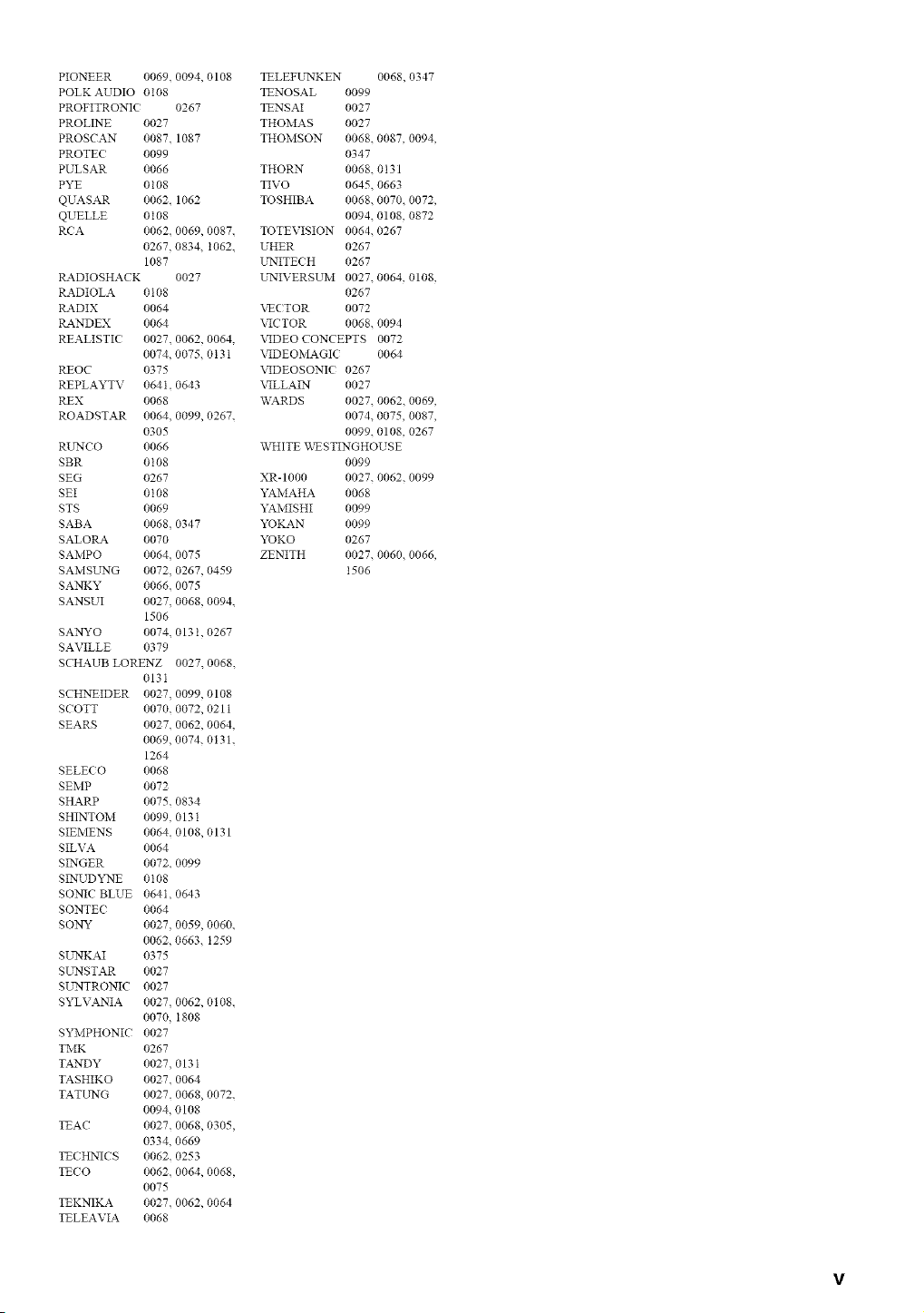
PIONEER 0069. 0094, 0108
POLK AUDIO 0108
PROFITRONI( 0267
PROLINE 0027
PROSCAN 0087. 1087
PROTE( 0099
PULSAR 0066
PYE 0108
QUASAR 0062. 1062
QUELLE 0108
R(A 0062. 0069, 0087.
0267, 0834. 1062.
1087
P_&DIOSHACK 0027
RADIOLA 0108
RADIX 0064
P_&NDEX 0064
REALISTI( 0027. 0062, 0064.
0074, 0075.0131
REOC 0375
REPLAYTV 0641. 0643
REX 0068
ROADSTAR 0064. 0099, 0267.
0305
RUNCO 0066
SBR 0108
SEG 0267
SEI 0108
STS 0069
SABA 0068 0347
SALORA 0070
SAMPO 0064 0075
SAMSL_rNG 0072 0267, 0459
SANKY 0066. 0075
SANSUI 0027 0068, 0094.
1506
SA_Nryo 0074, 0131, 0267
SAVILLE 0379
SCHAUB LORENZ 0027. 0068.
013I
SCHNEIDER 0027 0099, 0108
SCOTT 0070, 0072, 0211
SEARS 0027. 0062, 0064,
0069, 0074. 0131.
1264
SELECO 0068
SEMP 0072
SHARP 0075. 0834
SHINTOM 0099, 0131
SIEMENS 0064 0108, 0131
SILVA 0064
SINGER 0072. 0099
SINUD "*EX'E 0108
SONIC BLUE 064I, 0643
SONTE( 0064
SONY 0027 0059, 0060.
0062, 0663. 1259
SUNKAI 0375
SUNSTAR 0027
SL_'NTRONIC 0027
SYLVANIA 0027 0062, 0108.
0070, 1808
SYMPHONIC 0027
TMK 0267
TANDY 0027. 013 I
TASHIKO 0027. 0064
TATUNG 0027. 0068, 0072.
0094, 0108
TEAC 0027. 0068, 0305,
0334, 0669
TE(HNICS 0062. 0253
TECO 0062. 0064, 0068,
0075
TEKNIKA 0027. 0062, 0064
TELEAVIA 0068
TELEFUNKEN 0068, 0347
TENOSAL 0099
TENSAI 0027
THOMAS 0027
THOMSON 0068. 0087, 0094,
0347
THORN 0068. 0131
TIVO 0645, 0663
TOSHIBA 0068, 0070, 0072,
0094. 0108, 0872
TOTEVISION 0064. 0267
UHER 0267
L'NITE( H 0267
UNIVERSUM 0027. 0064, 0108,
0267
\_(TOR 0072
VICTOR 0068. 0094
VIDEO CONCEPTS 0072
VIDEOMAGI( 0064
VIDEOSONI( 0267
VILLAIN 0027
WARDS 0027, 0062, 0069,
0074. 0075, 0087,
0099. 0108, 0267
WHITE _\_STINGHOUSE
0099
XR-1000 0027. 0062. 0099
YAMAHA 0068
YAMISHI 0099
YOKAN 0099
YOKO 0267
ZENITH 0027, 0060, 0066,
1506
v

_)2005 YAMAHA CORPORATION All rights reserved.
YAMAHA ELECTRONICS CORPORATION, USA 6660 ORARGETHORPE AVE., BUENA PARK, CALIF. 90620, U.S.A.
YAMAHA CANADA MUSIC LTD. 135 MILNER AVE., SOARBOROUGH, ONTARIO M1S 3R1, CANADA
YAMAHA ELECTRONIK EUROPA G.rn,b.H. SIEMENSSTR. 22-34, 25462 RELLINGEN BEI HAMBURG, GERMANY
YAMAHA ELECTRONIQUE FRANCE S.A. RUE AMBROISE CROIZAT BP70 CROISSY-BEAUBOURG 77312 MARNE-LA-VALLEE CEDEX02, FRANCE
YAMAHA ELECTRONICS (UK) LTD. YAMAHA HOUSE, 200 RICKMANSWORTH ROAD WATFORD, HERTS WD18 7GQ, ENGLAND
YAMAHA SCANDINAVIA A.B. J A WETTERGRENS GATA 1, BOX 30053, 400 43 VASTRA FROLUNDA, SWEDEN
YAMAHA MUSIC AUSTRALIA PTY, LTD, 17-33 MARKET ST., SOUTH MELBOURNE, 3205 VIG., AUSTRALIA
YAMAHA CORPORATION
Printed in Malaysia C WF09590