Loading ...
Loading ...
Loading ...
ASS
TOOLS REQUIRED FOR ASSEMBLY
1 - Knife (to cut carton and plastic ties)
2 - 1/2 inch wrenches (or adjustable wrenches)
2 - 9/16 inch wrenches (or adjustable wrenches)
2 - 3/4 inch wrenches (or adjustable wrenches)
1 - P_iers(to spread cotter pin)
1- Screwdriver
1 - Measuring Tape or Ruler
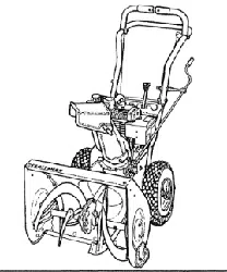
Figure 1 shows the snow throwerinthe shipping position.,
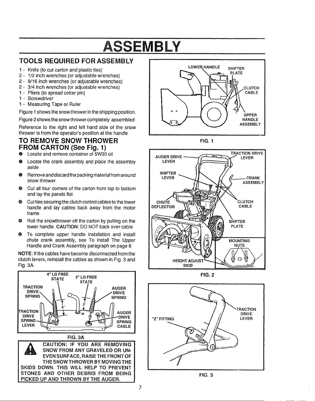
Figure 2showsthe snowthrower completely assembled.
Reference to the right and left hand side of the snow
thrower is from the operator's position at the handle,
TO REMOVE SNOW THROWER
FROM CARTON (See Fig. 1)
® Locate and remove container of 5W30 oil
®
®
®
®
Locate the crank assembly and place the assembly
aside
Remove anddiscardthe packing material from around
snow thrower.
Cut all four corners of the carton from top to bottom
and lay the panels fiat,
Cutties securing the clutch control cables to the lower
handle and lay cables back away from the motor
frame
® Roll the snowthrower off the carton by pulling on the
lower handle,, CAUTION: DO NOT back over cable
® To complete upper handle installationand install
chute crank assembly, see To Install The Upper
Handle and Crank Assembly paragraph on page 8
NOTE: Ifthe cables have become disconnected from the
clutch levers, reinstall the cables as shown in Fig 3 and
Fig, 3A,,
4" LG FREE
STATE 3" LG FREE
STATE
TRACTION _ / ,q AUGER
DRIVE,. "t_, / H -- DRIVE
[ r%
DRIVEll _/_ ""- - $ '_L_.4"'DR_VE
SPRING_ _ If SPRING
LEVER °ABLE
FIG. 3A
,_ CAUTION: IF YOU ARE REMOVINGSNOW FROM ANY GRAVELED OR UN-
EVEN SURFACE, RAISE THE FRONTOF
THE SNOW THROWER BY MOVING THE
SKIDS DOWN° THIS WILL HELP TO PREVEN_
STONES AND OTHER DEBRIS FROM BEING
PICKED UP AND THROWN BY THE AUGER.
LY
i i iii,i i i
LOWEF
SHIFTER
PLATE
UPPER
AUGER DRIVE
LEVER
SHIFTER
LEVER
CHUTE
DEFLECTOR
HEIGHT ADJUST
SKID
"Z'FITTING
HANDLE
ASSEMBLY
FIG. 1
TRACTION DRIVE
LEVER
FIG. 2
FION
DRIVE
LEVER
FIG. 3
7
Loading ...
Loading ...
Loading ...