Loading ...
Loading ...
Loading ...
Section5: Maintenance
_ eforeinspecting,cleaningorservicingthemachine,shutoffengine,waitformovingpartstostop,disconnectspank
plugwireandmovewireawayfromspankplug.Removeignitionkey(electricstartmodels).
Failuretofollowtheseinstructionscanresultinseriouspersonalinjur/orpropertydamage.
BLADEBRAKEREPLACEMENT
Followthis procedureto installa new
bladebrake.
ToRemoveBladeBrake:
1. Stopengine,waitforall partsto
stopmoving,anddisconnectspark
plugwire.
2. Removebeltcoverasdescribedin
"Belt CoverRemoval"instructions.
3. Removehardware(G,Figure5-8)
securingbladebrake(H).
4. Removeold brake(H)from idler
arm (I).
ToInstall Brake:
1. Positionnewbrake(H) in placeon
idlerarm (I).
2. Centerbrakein sheavegrooveand
securebrake(H)with hardware(G)re-
movedearlier.
3. Reinstallbeltcoversecurely.
4. Testoperationof bladebrake(see
"BladeBrakeControlTest" in Operation
section).
BLADEDRIVEBELT
ADJUSTMENT
If thebladedrive beltis slippingdueto
lackof belttension,follow thesteps
below.
1. Stopengine,waitforall partsto
stopmoving,anddisconnectspark
plugwire.
2. Removebeltcoverasdescribedin
"Belt CoverRemoval"instructions.
3. With moweron levelground,adjust
bladecutting heightatabout3" (mea-
surefrom ground to flat portion of
blade).
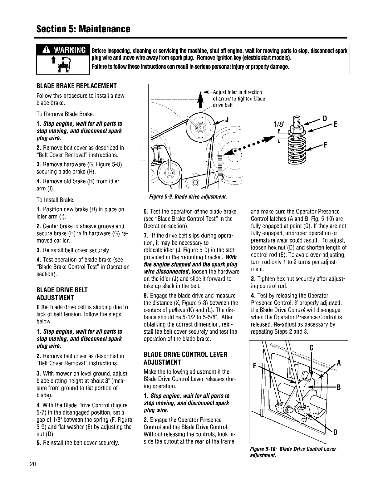
4. Withthe BladeDriveControl(Figure
5-7) inthedisengagedposition,seta
gapof 1/8" betweenthespring (F,Figure
5-9) andflat washer(E)byadjustingthe
nut(D).
5. Reinstallthe beltcoversecurely.
2O
-_--Adjust idlerin direction
of arrow to tighten blade
f drive belt
D
Figure5-9: Bladedriveadjustment.
6. Testthe operationofthe bladebrake
(see"BladeBrakeControlTest"in the
Operationsection).
7. If thedrive beltslips during opera-
tion, it maybenecessaryto
relocateidler (J, Figure5-9) intheslot
providedinthe mountingbracket. With
theenginestoppedandthesparkplug
wiredisconnected,loosenthehardware
onthe idler (J) andslideit forward to
take upslackinthe belt.
8. Engagethe bladedriveand measure
the distance(X,Figure5-8) betweenthe
centersof pulleys(K) and(L). Thedis-
tanceshould be5-1/2to 5-5/8". After
obtainingthecorrect dimension,rein-
stallthe beltcoversecurelyandtestthe
operationofthe bladebrake.
BLADEDRIVECONTROLLEVER
ADJUSTMENT
Makethefollowing adjustmentif the
BladeDriveControl Leverreleasesdur-
ing operation.
1. Stopengine,waitforall partsto
stopmoving,anddisconnectspark
plugwire.
2. Engagethe OperatorPresence
ControlandtheBladeDriveControl.
Withoutreleasingthe controls, lookin-
sidethe cutoutatthe rearof theframe
and makesurethe OperatorPresence
Controllatches(Aand B,Fig.5-10) are
fully engagedat point (C).If they arenot
fully engaged,improperoperationor
prematurewearcould result. To adjust,
loosenhexnut (D)andshorten lengthof
control rod(E).Toavoidover-adjusting,
turn rodonly 1 to 2 turns peradjust-
ment.
3. Tighten hexnutsecurelyafter adjust-
ingcontrol rod.
4. Testby releasingtheOperator
PresenceControl.If properlyadjusted,
the BladeDriveControlwill disengage
whentheOperatorPresenceControlis
released.Re-adjustasnecessaryby
repeatingSteps2 and3.
Figure5-10: BladeDriveControlLever
adjustment.
Loading ...
Loading ...
Loading ...