TROKBILT'____
Operator's Manual
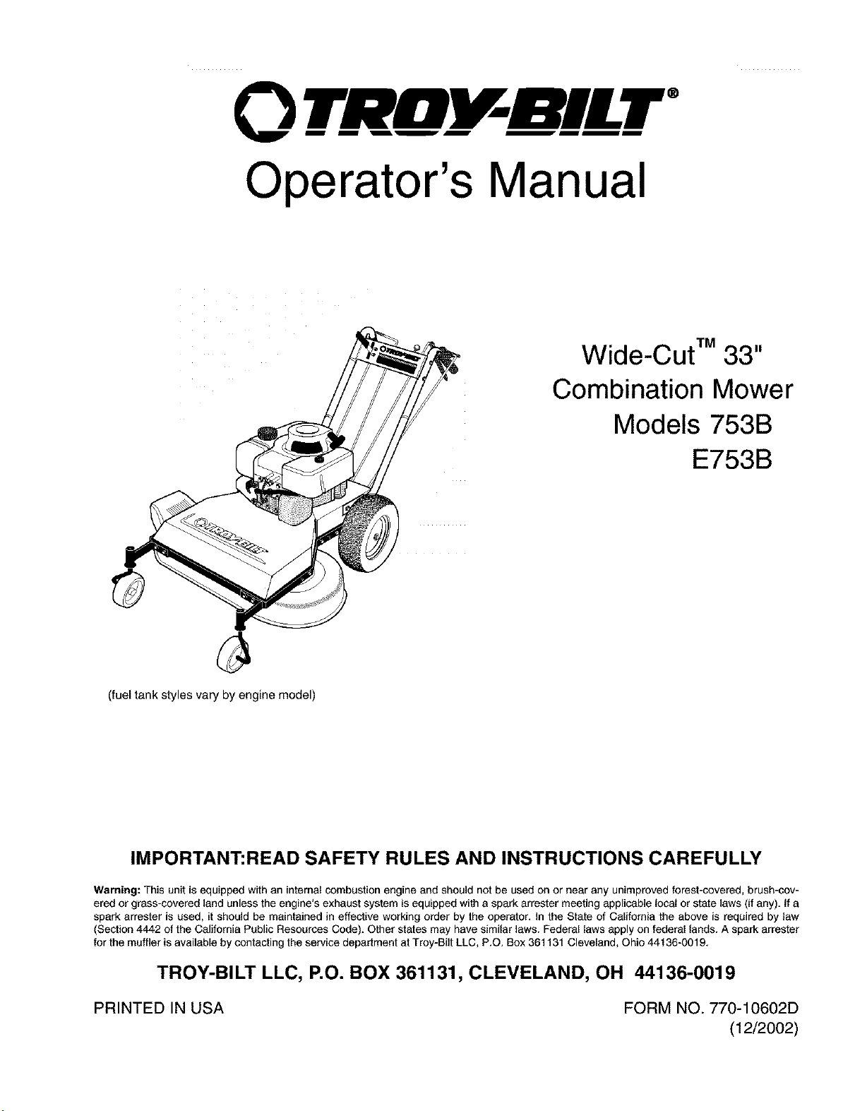
Wide-Cut TM 33"
Combination Mower
Models 753B
E753B
(fuel tank styles vary by engine model)
IMPORTANT:READ SAFETY RULES AND INSTRUCTIONS CAREFULLY
Warning: This unit is equipped with an internal combustion engine and should not be used on or near any unimproved forest-covered, brush-cov-
ered or grass-covered land unless the engine's exhaust system isequipped with a spark arrester meeting applicable local or state laws (if any). if a
spark arrester is used, it should be maintained in effective working order by the operator. In the State of California the above is required by law
(Section 4442 of the California Public Resources Code). Other states may have similar laws. Federal laws apply on federal lands. A spark arrester
for the muffler is available by contacting the service department at Troy-Bilt LLC, P.O. Box 361131 Cleveland, Ohio 44136-0019.
TROY-BILT LLC, P.O. BOX 361131, CLEVELAND, OH 44136-0019
PRINTED IN USA FORM NO. 770-10602D
(12/2002)
TABLEOFCONTENTS
Content Page
Safety ................................................................... 1
Assembly ................................................................. 4
Features and Controls ....................................................... 8
Operation ................................................................ 11
Maintenance .............................................................. 16
Off-Season Storage ........................................................ 24
Lubrications ............................................................... 25
Troubleshooting ........................................................... 27
Parts List ................................................................. 28
Warrany Information ........................................................ Back Cover
FINDING MODEL NUMBER
This Operator's Manual isan important part of your new Wide-Cut TM mower. It will help you assemble, prepare and
maintain the unit for best performance. Please read and understand what it says.
Before you start assembling your new equipment, please locate the model plate on the equipment and copy the infor-
mation from it in the space provided below. This informationis very important if you need help from our Customer
Support Department or an authorized dealer.
You can locate the model number by looking at the rear surface of the tine shield. A sample model plate is ex-
plained below. For future reference, please copy the model number and the serial number of the equipment in
the space below
O BILT" TROY-BILT LL(
P* O* BOX 361131
www.troybilt.com CLEVELAND,OH44136
330-558-7220
• 866-840-6483,
Copy Model Number Here
Copy Serial Number Here
ENGINEINFORMATION
The engine manufacturer is responsible for all engine-related issueswith regards to performance, power-rating,
specifications, warranty and service. Please refer to the engine manufacturer's Owner's/Operator's Manual packed
separately with your unit for more information.
CALLING CUSTOMER SUPPORT
If you have difficulty assembling this product or have any questions regarding the controls, operation or maintenance
of this unit, please ca]] the Customer Support Department.
Call 1- (330) 558-7220 or 1- (866) 840-6483 to reach a Customer Support representative. Please have
your unit's model number and serial number ready when you call. See previous section to locatethis in-
formation. You will be asked to enter the serial number in order to process your call.
Safety
WARNING:
The engine exhaust from this product contains
chemicals known to the State of California
to cause cancer, birth defects, or other reproduc-
tive harm.
SafetyAlertSymbol
,_ This is a safety alert symbol. It is used in this
Owner's Manual to alert you to potential
hazards. Wheneveryou seethis symbol, readand obeythe
safety messagethat follows it. Failureto obey the safety
message could result in personal injury or property
damage.
IMPORTANT
Safe Operation Practices for Walk-Behind Mowers
This cutting machine is capable of amputating hands and feet and throwing objects. Failure to observethe
following safety instructionscould result in serious injury or death.
I. GENERALOPERATION 5
1. Read,understand,andfollow all in-
structionson the machineandin the
manuals.Bethoroughly familiar with
thecontrolsandthe proper useof
the mowerbeforestarting. 6.
2. Donot put handsor feet nearor
under rotatingparts.Keepclearof
the mowerbladeand discharge 7.
openingatall times.
,
3. Onlyallowresponsibleindividuals,
whoarefamiliar with the instruc- 9.
tions, to operatethe mower.
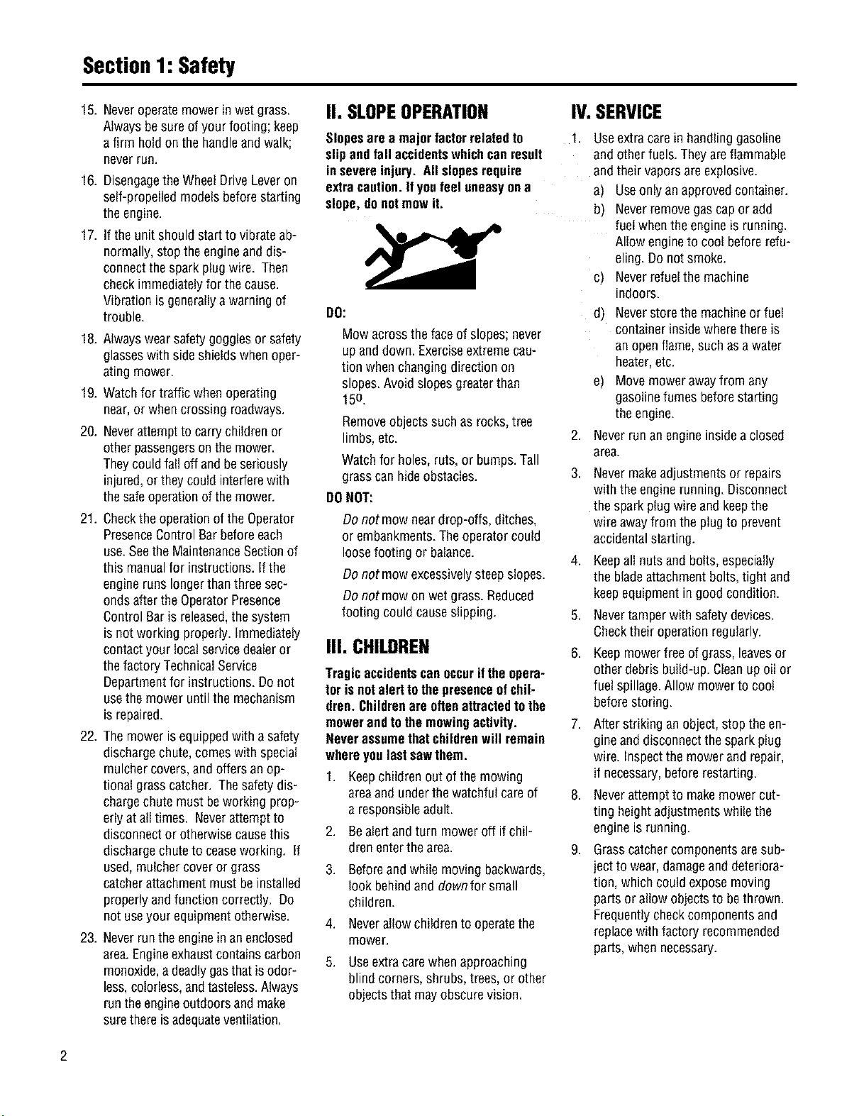
4. Clearthe areaof objectssuchas
rocks, toys,wire, bones,sticks,etc.,
which couldbe pickedupand
thrown bythe blade. 10.
11.
Besuretheareaisclearof other
peoplebeforemowing.Stopmower
if anyoneentersthe area. Keepby-
standersat least25 feetawayfrom
theareaof operation.
Donot operatethe mowerwhen
barefootor wearingopensandals.
Alwayswearsubstantialfoot wear.
Donot pull mower backwards
unlessabsolutelynecessary.Look
downand behindbeforeandwhile
moving backwards.
Donot operatethe mowerwithout
properguards, plates,grasscatcher
or othersafety protectivedevicesin
place.
Referto providedinstructionsfor
properoperationand installationof
accessories.Onlyuseaccessories
approvedbyGardenWay
Incorporated.
Stopthebladewhencrossinggravel
drives,walks, or roads,
Stoptheengineanddisconnectthe
sparkplug wirefrom thespark plug
wheneveryou leavethe unit, before
cleaningthemoweror unclogging
the chute.
12. Shuttheengineoff, wait until the
bladecomesto a completestop, and
disconnectthespark plugwire be-
fore installing or removingthe
mulchercoveror the optionalgrass
catcher. Makecertainthatthegrass
catcheris securelyattachedbefore
operatingthemower.Emptythe
grasscatcheraftereachuse-
decomposingdebriscouldgenerate
enoughheatto catchfire.
13. Mow in daylightor goodartificial
light.
14. Donotoperatethemower while
underthe influenceofalcoholor
drugs.
Section1:Safety
15. Neveroperatemowerin wet grass.
Alwaysbesureofyour footing; keep
a firm holdon thehandleand walk;
neverrun.
16. DisengagetheWheelDriveLeveron
self-propelledmodelsbeforestarting
the engine.
17. If the unitshouldstartto vibrateab-
normally,stop theengineanddis-
connectthesparkplug wire. Then
checkimmediatelyfor thecause.
Vibrationis generallya warningof
trouble.
18. Alwayswearsafetygogglesor safety
glasseswith sideshieldswhenoper-
ating mower.
19. Watchfor traffic whenoperating
near,or whencrossingroadways.
20. Neverattemptto carrychildrenor
otherpassengerson themower.
Theycouldfall off and beseriously
injured,or theycould interferewith
thesafeoperationofthemower.
21. Checkthe operationof theOperator
PresenceControlBarbeforeeach
use.SeetheMaintenanceSectionof
this manualfor instructions.If the
engineruns longerthanthreesec-
ondsafter theOperatorPresence
ControlBaris released,thesystem
is notworking properly.Immediately
contactyour localservicedealeror
thefactory TechnicalService
Departmentfor instructions.Donot
usethemower until themechanism
is repaired.
22. Themower isequippedwith a safety
dischargechute,comeswith special
mulchercovers,and offersanop-
tional grasscatcher. Thesafetydis-
chargechute must beworking prop-
erlyat all times. Neverattemptto
disconnector otherwisecausethis
dischargechuteto ceaseworking. If
used,mulchercoveror grass
catcherattachmentmust be installed
properlyandfunction correctly. Do
notuseyour equipmentotherwise.
23. Neverruntheengineinanenclosed
area.Engineexhaustcontainscarbon
monoxide,adeadlygasthat isodor-
less,colorless,andtasteless.Always
runtheengineoutdoorsand make
surethereisadequateventilation.
II. SLOPEOPERATION
Slopeseree majorfactorrelatedto
slipandfall accidentswhichcanresult
insevereinjury. Allslopesrequire
extracaution.Ifyoufeel uneasyone
slope,donotmow it.
DO:
Mow acrossthefaceof slopes;never
up anddown. Exerciseextremecau-
tion whenchangingdirection on
slopes.Avoidslopesgreaterthan
15o.
Removeobjectssuch asrocks,tree
limbs,etc.
Watchfor holes, ruts,or bumps.Tall
grasscanhideobstacles.
DONOT:
Donot mow neardrop-offs, ditches,
or embankments.Theoperatorcould
loosefooting or balance.
Donot mowexcessivelysteepslopes.
Donot mowon wet grass.Reduced
footing couldcauseslipping.
III. CHILDREN
Tragicaccidentscanoccuriftheopera-
tor isnotalerttothepresenceofchil-
drem Childrenereoftenattractedtothe
mowerandtothemowingactivity.
Neverassumethatchildrenwill remain
whereyoulastsewthem.
1. Keepchildrenout of themowing
areaand underthewatchful careof
a responsibleadult.
2. Bealertandturn moweroff ifchil-
dren enterthearea.
3. Beforeandwhile moving backwards,
look behindand downfor small
children.
4. Neverallowchildrento operatethe
mower.
5. Useextracarewhenapproaching
blind corners,shrubs,trees,or other
objectsthat mayobscurevision.
IV.SERVICE
1. Useextracarein handlinggasoline
andotherfuels.Theyareflammable
andtheirvapors areexplosive.
a) Useonlyan approvedcontainer.
b) Neverremovegascapor add
fuelwhentheengineis running.
Allowengineto cool beforerefu-
eling.Do notsmoke.
c) Neverrefuelthe machine
indoors.
d)
e)
Neverstorethemachineor fuel
containerinsidewherethereis
an openflame,such asawater
heater,etc.
Movemowerawayfrom any
gasolinefumesbeforestarting
theengine.
2. Neverrunan engineinsidea closed
area.
,
Nevermakeadjustmentsor repairs
with the enginerunning. Disconnect
the spark plugwireand keepthe
wireawayfrom the plugto prevent
accidentalstarting.
4. Keepall nuts and bolts,especially
the bladeattachmentbolts,tight and
keepequipmentin goodcondition.
5. Nevertamperwith safetydevices.
Checktheir operationregularly.
,
Keepmowerfreeof grass,leavesor
otherdebrisbuild-up.Cleanupoil or
fuel spillage.Allowmowerto cool
beforestoring.
7,
After striking anobject,stop theen-
gineand disconnectthespark plug
wire. Inspectthemowerand repair,
if necessary,beforerestarting.
8. Neverattemptto makemowercut-
ting heightadjustmentswhilethe
engineis running.
,
Grasscatchercomponentsaresub-
ject to wear,damageanddeteriora-
tion, whichcouldexposemoving
partsor allowobjectsto bethrown.
Frequentlycheckcomponentsand
replacewith factory recommended
parts,whennecessary.
2
Section1:Safety
10. Mower bladesare sharpandcan
cut. Wrapthe bladeor weargloves,
and useextracautionwhenservic-
ing them.
11. Donot changetheenginegovernor
settingor overspeedtheengine.
12. Donot touch enginepartswhich
may behotfrom operation.Allow
parts to coolcompletelybeforein-
specting,cleaningor repairingthe
mower,
13.
14.
15.
To accessthe undersideof the
mower,tip the mower rearward.Do
nottip the mowerforward or on ei-
ther of its sides,unlessspecifically
advisedto do so in this manual.
Maintainor replacesafetyand in-
structionaldecals. Referto thesep-
aratePartsCatalogfor replacement
decalinformation.
Forunitsequippedwith electric
start:
a) Batteriesproduceexplosive
gases.Keepsparks,flame,
cigarettes,etc.,away. Ventilate
theareawhenchargingthe bat-
tery.Donotchargethebatteryin
anairtight space.
b) Donot usea batterycharger
otherthantheone providedwith
the mower.
c) Thebatterycontainstoxic mate-
rials. Donotdamagethe battery
case.If the caseis brokenor
damaged,avoidcontactwith the
batterycontents.
d) Properlydisposeof adamaged
or worn out battery.Checkwith
localauthoritiesfor properdis-
posalmethods.
e) Donotshort circuitthe battery.
Severeburnsandfire canresult.
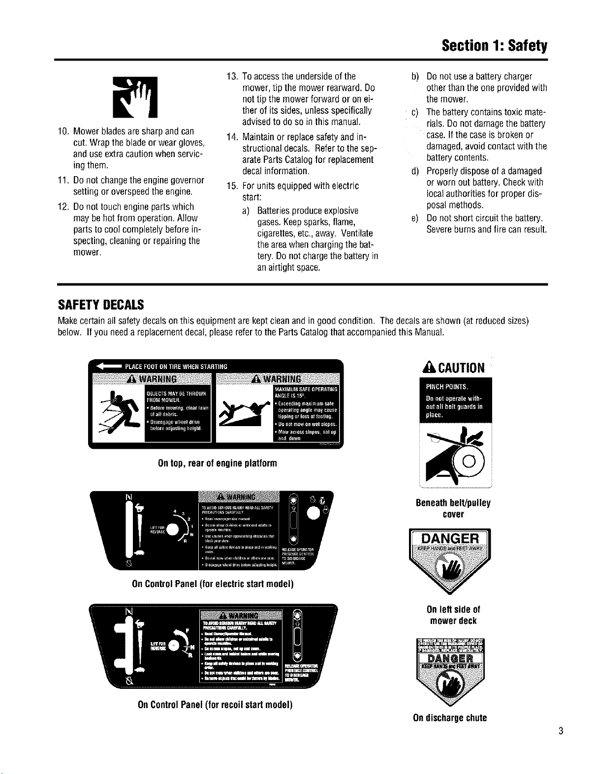
SAFETYDECALS
Makecertainall safetydecalsonthis equipmentarekeptcleanand in goodcondition. Thedecalsareshown (at reducedsizes)
below. Ifyou needa replacementdecal,pleasereferto the PartsCatalogthataccompaniedthis Manual.
CAUTION
Ontop,rearofengineplatform
OnControlPanel(forelectricstartmodel)
Beneathbelt/pulley
cover
DANGER
Onleft sideof
mowerdeck
OnControlPanel(for recoilstartmodel)
Ondischargechute
3
4
ASSEMBLYSTEPS
To preventpersonalinjuryor property
damage, do not attempt to start the
engine until all assembly steps are
complete and you have read and
understand the safety, controls and
operatinginstructionsinthismanual.
INTRODUCTION
Pleasecarefullyfollow theseassembly
stepsto properlyprepareyour machine
for use. Werecommendthat you read
this Sectioninits entiretybeforebegin-
ningassembly.
NOTE:All referencesto left, right, front
andrearof the machinearedetermined
bystandingbehindthe handlebarsand
facing thedirectionof forward travel.
INSPECTION AFTER DELIVERY
inspectthe shippingcrateand machine
immediatelyafter delivery. Makesure
neitherthecarton northe contentshave
beendamaged.
ifyoufind or suspectanydamage,con-
tact thecarrier(truckingcompany)
immediately. Inform themof thespecific
damageandthatyou wish to file aclaim.
To protectyour rights, besureto put
this inwriting tothe carrierwithin 15
days. Thecarrierwill letyou know how
to proceedwith your claim. Pleaseletus
know ifyou needanyassistance.
STEP1: Unpacking Mower
NOTE:LEFTandRIGHTsidesof the unit
areasviewedfrom the operator'sposi-
tion behindthe handlebars.
1. Cutstraps,if present,securingunit
to pallet. Leaveuniton palletduring as-
sembly(to safelyremoveunit from pal-
let,wait until you havecompletedas-
semblysteps1-4).
2. Removeany protectivepackaging
from aroundthehandlebars.Cutthe
plastictie strapsholdingthecontrol rods
and struts tothe handlebars.
STEP2: Attach Handlebars
to Engine Deck
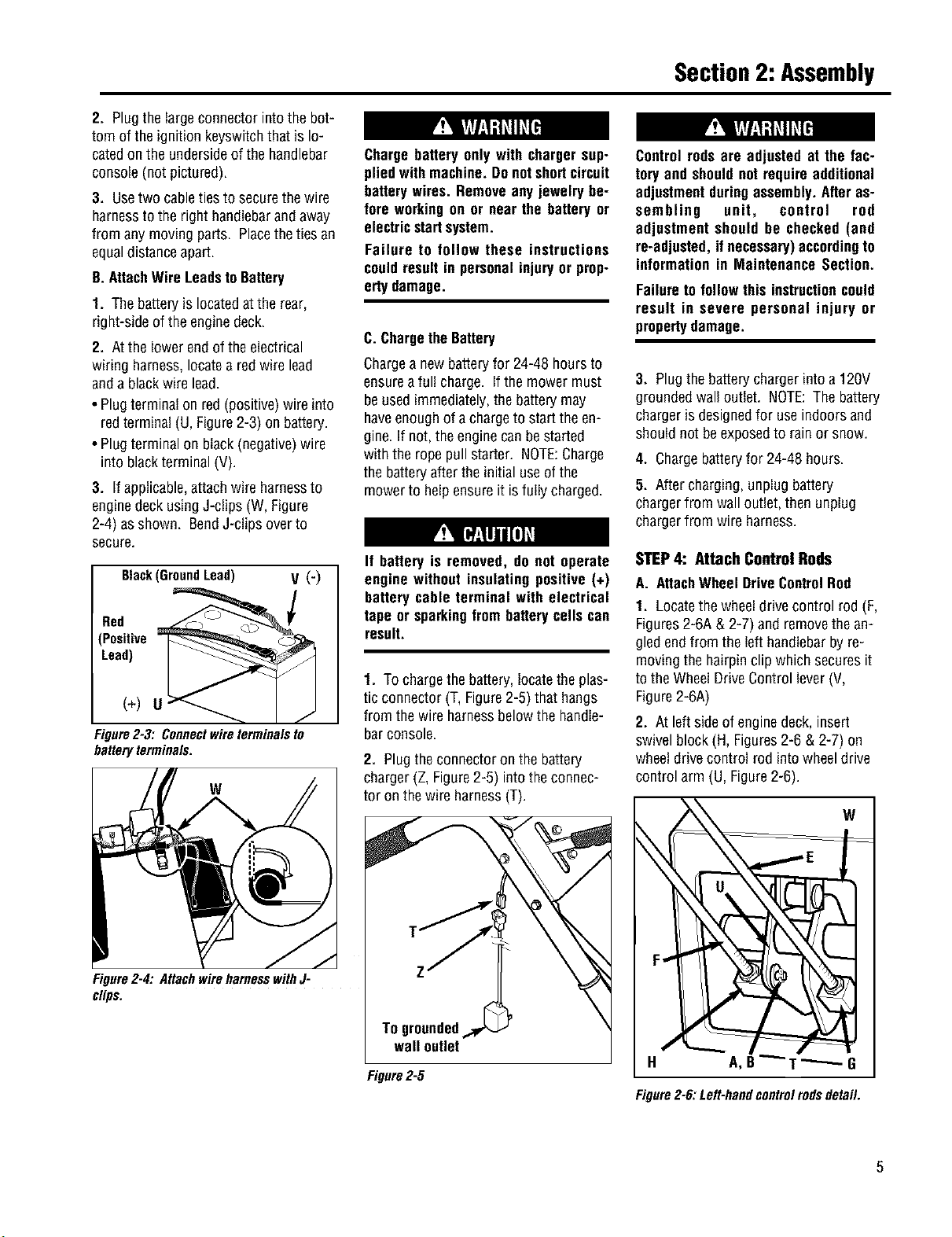
NOTE:Fourscrews(D, Figure2-2) are
usedto connectthehandlebarsto the
enginedeck. Atthefactory,two of these
screws (front) arethreadeddirectlyinto
lock nutsweldedto thebacksidesof the
deck.Theremainingtwo screws (rear)
securethe lower handletothe deck.
1. Removeand savethetwo 5/16"-18x
3/4"screws (front) mentionedinthe
NOTEabove.
2. Carefullypivot the handlebarsover
theengineand positionthe handlebar
ends(E,Figure2-2) againstthe sidesof
theenginedeck.Donotalloowthe han-
dlebarsto rubagainsttheenginewhile
pivotingthem.
3. Looselysecuretheright-handhandle-
TOOLS/MATERIALSNEEDED: barendto thedeck byreinsertingthe
• WireCutter screw (D,Figure2-2) removedearlier.
• Two 7/16" Wrenches Donotsecurethe left-handhandleat
• 3/8" Wrench this point inassembly.
• 1/2" Wrench 4. Removethe nutfrom the lowerscrew
• Scissorsor PenKnife (B,Figure2-1) which securesthe con-
soleto the handlebaron theleft-hand
• Needle-nosePliers sideof the unit.
• TireGauge
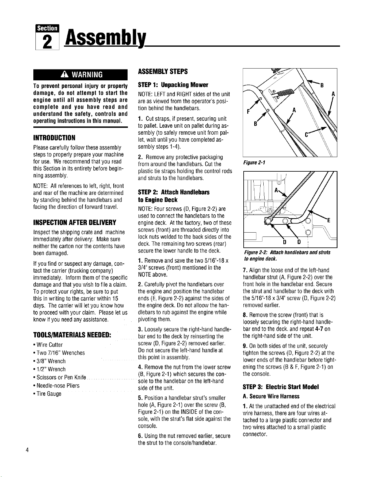
5. Positiona handlebarstrut's smaller
hole(A,Figure2-1) overthescrew (B,
Figure2-1) on theINSIDEof thecon-
sole, with thestrut's fiat sideagainstthe
console.
6. Usingthenut removedearlier,secure
thestrut to theconsole/handlebar.
Figure2-1
Figure2-2: Attachhandlebarsandstruts
toenginedeck,
7. Align the looseendof the left-hand
handlebarstrut (A, Figure2-2) overthe
front holeinthe handlebarend.Secure
thestrut and handlebarto thedeckwith
the5/16"-18x 3/4"screw(D, Figure2-2)
removedearlier.
8. Removethescrew(front) that is
looselysecuringthe right-handhandle-
barendto thedeck.and repeat4-7 on
the right-handsideof theunit.
9. Onbothsidesof theunit, securely
tighten thescrews(D, Figure2-2) atthe
lowerendsofthe handlebarbeforetight-
eningthe screws(B & F,Figure2-1) on
theconsole.
STEP3: Electric Start Model
A. SecureWireHarness
1. At theunattachedendof theelectrical
wire harness,therearefour wiresat-
tachedtoa large plasticconnectorand
two wires attachedto a small plastic
connector.
Section2: Assembly
2. Plugthe largeconnectorintothe bot-
tom of the ignitionkeyswitchthat is lo-
catedonthe undersideof the handlebar
console(not pictured).
3. Usetwo cabletiesto securethewire
harnessto the right handlebarandaway
from any movingparts. Placetheties an
equaldistanceapart.
B. AttachWireLeadsto Battery
1. Thebatteryis locatedatthe rear,
right-sideofthe enginedeck.
2. Atthe lowerendofthe electrical
wiring harness,locatea redwire lead
anda blackwire lead.
• Plugterminal on red(positive)wireinto
redterminal(U, Figure2-3) on battery.
• Plugterminalon black(negative)wire
into blackterminal (V).
3. Ifapplicable,attachwire harnessto
enginedeckusingJ-clips (W, Figure
2-4) asshown. BendJ-clips overto
secure.
Black(GroundLead) V (')
Bed
(Positive =
Lead)
(+) U
Figure2-3: Connectwireterminalsto
batteryterminals,
W
Figure2-4: AttachwireharnesswithJ-
clips.
Chargebattery onlywith chargersup-
pliedwith machine.Donotshortcircuit
batterywires. Removeanyjewelrybe-
fore workingon or nearthe batteryor
electricstartsystem.
Failure to follow these instructions
couldresultin personalinjuryor prop-
ertydamage.
C. ChargetheBattery
Chargea newbatteryfor 24-48 hoursto
ensureafull charge. If the mowermust
be usedimmediately,the batterymay
haveenoughof a chargeto startthe en-
gine.If not,theenginecanbestarted
with the ropepull starter. NOTE:Charge
thebatteryafter theinitial useof the
mowerto helpensureit isfully charged.
If battery is removed, do not operate
engine without insulating positive (+)
battery cable terminal with electrical
tape or sparkingfrom batteryceils can
result.
1. Tochargethe battery,locatethe plas-
tic connector(T, Figure2-5) that hangs
from the wireharnessbelowthe handle-
barconsole.
2. Plugtheconnectoron the battery
charger(Z, Figure2-5) intotheconnec-
tor on thewire harness(T).
Togrounded
wall outlet
Figure2-5
Controlrodsare adjusted at the fac-
tory andshouldnot requireadditional
adjustmentduringassembly.Afteras-
sembling unit, control rod
adjustment should be checked(and
re-adjusted,ifnecessary)accordingto
informationin MaintenanceSection.
Failureto followthis instructioncould
result in severe personal injury or
propertydamage.
3. Plugthebatterychargerinto a120V
groundedwall outlet. NOTE:Thebattery
chargeris designedfor useindoorsand
shouldnot beexposedto rainor snow.
4. Chargebatteryfor 24-48 hours.
5. After charging,unplug battery
chargerfrom wall outlet,then unplug
chargerfrom wire harness.
STEP4: Attach Control Rods
A. AttachWheelDriveControlRod
1. Locatethe wheeldrivecontrol rod (F,
Figures2-6A & 2-7) and removethean-
gledendfrom theleft handlebarbyre-
movingthe hairpinclipwhich securesit
to the WheelDriveControllever(V,
Figure2-6A)
2. At left sideof enginedeck,insert
swivelblock(H, Figures2-6 & 2-7) on
wheeldrivecontrol rod into wheeldrive
control arm(U, Figure2-6).
W
H A,E _ T "----" G
Figure2-6: Left-handcontrolrodsdetail.
Section2: Assembly
BB
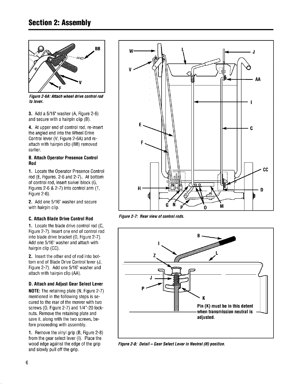
Figure2-6A:Attachwheel drivecontrolrod
tolever.
3. Adda 5/16"washer(A,Figure2-6)
andsecurewith ahairpinclip (B).
4. At upperend of control rod,re-insert
theangledendintothe WheelDrive
Controllever(V,Figure2-6A)and re-
attachwith hairpinclip (BB) removed
earlier.
B. AttachOperatorPresenceControl
Rod
1. Locatethe OperatorPresenceControl
rod (E,Figures.2-6and 2-7). At bottom
of control rod, insertswivelblock (G,
Figures2-6 & 2-7) intocontrol arm (T,
Figure2-6).
2. Addone5/16"washerandsecure
with hairpinclip.
C. AttachBladeDriveControlRod
1. Locatethe bladedrivecontrol rod(C,
Figure2-7). Insertoneend ofcontrol rod
intobladedrive bracket(D, Figure2-7).
Addone 5/16"washerandattachwith
hairpinclip(CC).
2. Inserttheotherendof rodinto bot-
tom end of BladeDriveControllever(J,
Figure2-7). Addone 5/16"washerand
attachwith hairpinclip (AA).
D.AttachandAdjustGearSelectLever
NOTE:Theretainingplate(N, Figure2-7)
mentionedin thefollowing stepsisse-
curedtothe rearof themower with two
screws(0, Figure2-7) and 1/4"-20 lock-
nuts.Removethe retainingplateand
saveit, alongwith thetwo screws,be-
fore proceedingwith assembly.
1. Removethevinyl grip (B,Figure2-8)
from the gearselectlever(I). Placethe
woodedgeagainsttheedgeof thegrip
andslowly pull off the grip.
W,_
L
AA
E_ t_ _ --C
-
] cc
! I ' ,
H] -G--N-:_ g D
Figure2-7: Rearviewof controlrods.
Z
K
Pin(K)mustbeinthis detent
whentransmissionneutralis - ._
adjusted.
Figure2-8: Detail- GearSelectLeverin Neutral(N) position.
Section2: Assembly
2. Insertnylon bushing(Z, Figure2-8)
upinto console(L).
3. Slidespringand washers(J)down
onto gearselectlever.
4. Insertgearselectlever(I) upthrough
nylonbushing(Z) inhandlebarconsole
(L).Guidepin (K)ongearselectleverinto
groovein shiftquadrant(P).
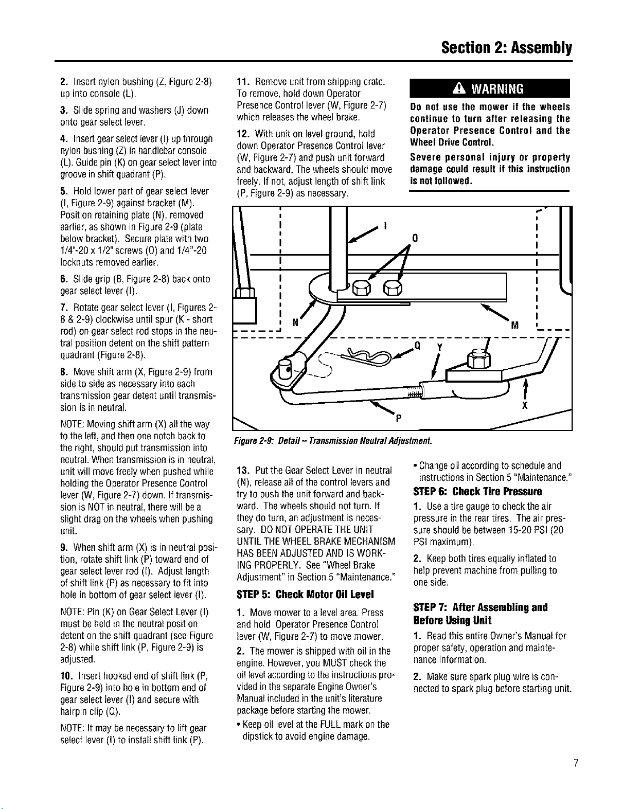
5. Holdlowerpartof gearselectlever
(I, Figure2-9) againstbracket(M).
Positionretainingplate(N), removed
earlier,asshown in Figure2-9 (plate
belowbracket). Secureplatewithtwo
1/4"-20x 1/2"screws (0) and 1/4"-20
Iocknutsremovedearlier.
6. Slidegrip (B,Figure2-8) backonto
gearselectlever(I).
7. Rotategearselectlever(I,Figures2-
8 &2-9) clockwiseuntilspur (K - short
rod) ongearselectrod stopsin the neu-
tral positiondetenton the shift pattern
quadrant(Figure2-8).
8. Moveshift arm (X,Figure2-9) from
sideto sideasnecessaryintoeach
transmissiongeardetent untiltransmis-
sion isin neutral.
NOTE:Movingshift arm(X) allthe way
to theleft,andthenonenotch backto
theright, shouldputtransmissioninto
neutral.Whentransmissionisin neutral,
unitwill movefreelywhenpushedwhile
holdingtheOperatorPresenceControl
lever(W, Figure2-7) down. If transmis-
sion isNOTinneutral,therewill bea
slight dragonthe wheelswhenpushing
unit.
9. Whenshift arm (X) is in neutralposi-
tion, rotateshift link(P) toward endof
gearselectleverrod (I). Adjust length
of shift link (P) asnecessaryto fit into
holein bottomof gearselectlever(I).
NOTE:Pin(K) on GearSelectLever(I)
mustbeheld in theneutralposition
detenton theshift quadrant(seeFigure
2-8) while shift link(P, Figure2-9) is
adjusted.
10. Inserthookedendof shift link(P,
Figure2-9) into hole in bottomendof
gearselectlever(I) andsecurewith
hairpinclip(Q).
NOTE:It may benecessaryto lift gear
selectlever(I) to install shift link (P).
11. Removeunitfrom shippingcrate.
To remove,hold downOperator
PresenceControllever(W, Figure2-7)
which releasesthewheelbrake.
12. With uniton levelground,hold
downOperatorPresenceControllever
(W, Figure2-7) and pushunit forward
andbackward.Thewheelsshouldmove
freely. If not, adjust lengthof shift link
(P,Figure2-9) as necessary.
Do not use the mower if the wheels
continue to turn after releasing the
Operator Presence Control end the
WheelDriveControl.
Severe personal injury or property
damagecould resultif this instruction
is notfollowed.
; r'
I ._1 I
; ,f o ;
I I
J =
-...... ..... 77-
x
Figure2-9: Detail- TransmissionNeutralAdjustment.
13. Putthe GearSelectLeverin neutral
(N), releaseall of thecontrol leversand
try to pushthe unitforward andback-
ward. Thewheelsshould notturn. If
they do turn, anadjustment isneces-
sary. DONOTOPERATETHEUNIT
UNTILTHEWHEELBRAKEMECHANISM
HASBEENADJUSTEDANDISWORK-
INGPROPERLY.See"WheelBrake
Adjustment"inSection5 "Maintenance."
STEP5: Check Motor Oil Level
1. Movemowerto alevelarea.Press
andhold OperatorPresenceControl
lever(W, Figure2-7) to movemower.
2. Themower isshippedwith oil in the
engine.However,youMUSTcheckthe
oil levelaccordingto theinstructionspro-
videdin theseparateEngineOwner's
Manualincludedinthe unit'sliterature
packagebeforestartingthe mower.
• Keepoil levelatthe FULLmarkon the
dipstick to avoidenginedamage.
• Changeoil accordingto scheduleand
instructionsin Section5 "Maintenance."
STEP6: Check Tire Pressure
1. Useatire gaugeto checktheair
pressurein the reartires. Theair pres-
sureshouldbe between15-20 PSI(20
PSImaximum).
2. Keepboth tires equallyinflatedto
helppreventmachinefrom pullingto
oneside.
STEP7: After Assembling and
Before UsingUnit
1. Readthis entireOwner'sManualfor
propersafety,operationand mainte-
nanceinformation.
2. Makesuresparkplug wireis con-
nectedto sparkplug beforestarting unit.
FeaturesandControls
Before operating mower, be sure to
readall safety, controlsand operating
instructions in this Manual and on
decalslocatedonmachine.
Severe personal injury or property
damagecouldresult if this instruction
isnotfollowed.
IMPORTANT: THE MOWER IS
EQUIPPED WITH A BLADE-BRAKE-
CLUTCHCONTROLSYSTEMWHICHIS
DESIGNED TO STOP THE MOWER
BLADESWITHIN THREE(3) SECONDS
AFTER RELEASEOFTHE OPERATOR
PRESENCECONTROL. THIS SYSTEM
WILL STOPTHEBLADESBUTNOTTHE
ENGINE.THEREFORE,YOUCANDISEN-
GAGETHE BLADEDRIVEAT ANYTIME
WITHOUT HAVING TO STOP AND
RESTARTTHEENGINE.THIS FEATURE
IS PARTICULARLYUSEFULWHENYOU
NEEDTO CROSSGRAVELDRIVESOR
ROUGHTERRAIN AND YOU DO NOT
WANT THE SPINNING BLADES
TO STRIKE STONES OR HIDDEN
OBSTACLES.
MOWERFEATURESAND
CONTROLS
This sectiondescribesthevarious
featuresand controlson the unit. Refer
tothe nextsection"Operation"for
detailedoperatinginstructions. Also,
readtheseparateEngineOwner's
Manualfor a detailedexplanationofthe
proper useof theenginecontrols.
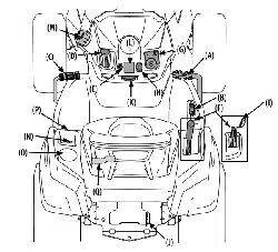
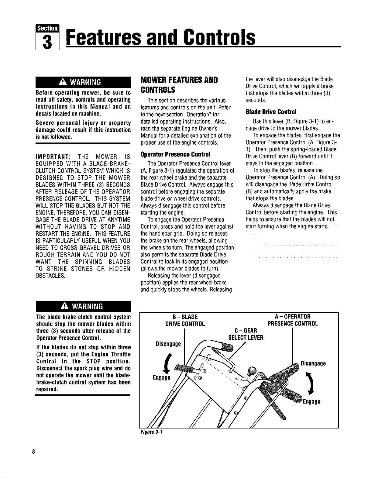
Operator Presence Control
TheOperatorPresenceControl lever
(A, Figure3-1) regulatesthe operationof
therearwheelbrakeand theseparate
BladeDriveControl. Alwaysengagethis
control beforeengagingthe separate
bladedrive or wheeldrivecontrols.
Alwaysdisengagethis control before
startingtheengine.
ToengagetheOperatorPresence
Control,pressand hold theleveragainst
thehandlebargrip. Doingso releases
thebrakeon the rearwheels,allowing
thewheelsto turn. Theengagedposition
alsopermitstheseparateBladeDrive
Controlto lock in its engagedposition
(allowsthe mowerbladesto turn).
Releasingthe lever(disengaged
position) appliestherearwheelbrake
andquicklystopsthewheels.Releasing
the leverwill alsodisengagethe Blade
DriveControl,which will applya brake
that stopsthe bladeswithin three(3)
seconds.
Blade Drive Control
Usethis lever(B,Figure3-1) to en-
gagedriveto the mowerblades.
Toengagetheblades,first engagethe
OperatorPresenceControl(A,Figure3-
1). Then,pushthe spring-loadedBlade
DriveControllever(B)forward until it
staysin theengagedposition.
Tostop the blades,releasethe
OperatorPresenceControl(A). Doingso
will disengagethe BladeDriveControl
(B)and automaticallyapplythe brake
that stopsthe blades.
Alwaysdisengagethe BladeDrive
Controlbeforestartingtheengine. This
helpsto ensurethatthe bladeswill not
startturningwhentheenginestarts.
The blade-brake-clutchcontrolsystem
shouldstop the mower blades within
three (3) secondsafter release of the
OperatorPresenceControl.
If the bladesdo not stopwithin three
(3) seconds, put the Engine Throttle
Control in the STOP position.
Disconnectthe sparkplug wire and do
not operatethe moweruntilthe blade-
brake-clutchcontrolsystemhas been
repaired.
B- BLADE
DRIVECONTROL
Disengage
Engage
C- GEAR
SELECTLEVER
A- OPERATOR
PRESENCECONTROL
Disengage
Engage
Figure3-1
Section3: FeaturesandControls
Operating Symbols Varioussymbolsare usedon the mowerto indicatecontrol settings(your modelmaynot haveall of the
symbols).Thesesymbolsareshown belowwith a descriptionof their meaning.
ENGINE ENGINE ENGINE
FAST SLOW CHOKE ENGAGE DISENGAGE STOP START RUN
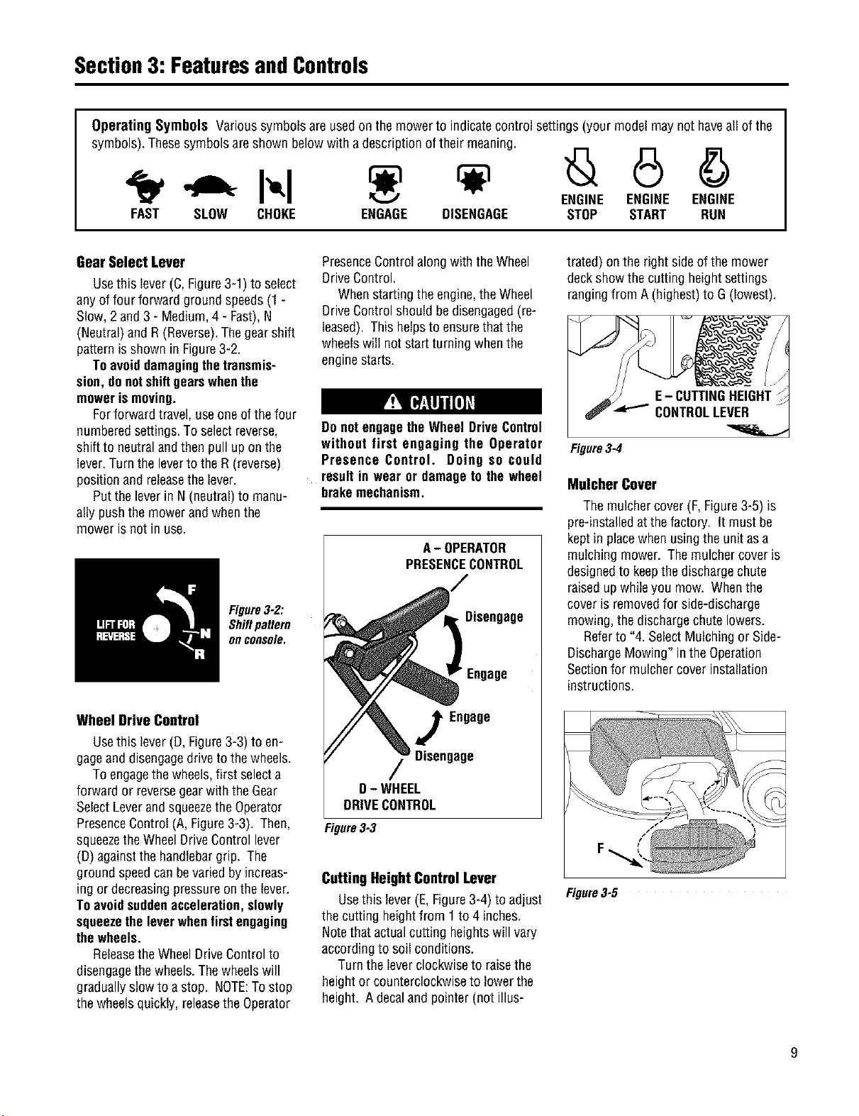
GearSelect Lever
Usethis lever(C,Figure3-1) to select
anyof four forward groundspeeds(1 -
Slow,2 and 3 - Medium,4- Fast),N
(Neutral)andR(Reverse).Thegearshift
patternisshown in Figure3-2.
Toavoiddamagingthetransmis-
sion,donotshiftgearswhenthe
mowerismoving.
Forforward travel,useoneofthe four
numberedsettings.Toselectreverse,
shiftto neutralandthenpull upon the
lever.Turnthe leverto theR (reverse)
positionand releasethe lever.
Putthe leverin N(neutral)to manu-
allypushthemowerand whenthe
mower isnot in use.
Figure3-2:
Shiftpattern
onconsole.
Wheel Drive Control
Usethis lever(D, Figure3-3) to en-
gageand disengagedriveto thewheels.
Toengagethe wheels,first selecta
forwardor reversegearwith theGear
SelectLeverandsqueezetheOperator
PresenceControl(A, Figure3-3). Then,
squeezetheWheelDriveControllever
(D)againstthehandlebargrip. The
groundspeedcanbevariedbyincreas-
ing or decreasingpressureon thelever.
Toavoidsuddenacceleration, slowly
squeezetheleverwhenfirstengaging
thewheels.
Releasethe WheelDriveControlto
disengagethewheels.Thewheelswill
graduallyslowto a stop. NOTE:Tostop
thewheelsquickly, releasethe Operator
PresenceControlalongwith theWheel
DriveControl.
Whenstartingthe engine,theWheel
DriveControlshouldbedisengaged(re-
leased). This helpsto ensurethat the
wheelswill notstartturning whenthe
enginestarts.
Do notengagethe WheelDriveControl
without first engaging the Operator
Presence Control. Doing so could
resultin wearor damageto the wheel
brakemechanism.
A- OPERATOR
PRESENCECONTROL
Disengage
Engage
Engage
Disengage
D- WHEEL
DRIVECONTROL
Figure3-3
Cutting Height Control Lever
Usethis lever(E,Figure3-4) to adjust
the cutting heightfrom 1to 4 inches.
Notethat actualcutting heightswill vary
accordingto soil conditions.
Turn theleverclockwiseto raisethe
heightor counterclockwiseto lowerthe
height. Adecaland pointer(not illus-
trated) onthe right sideofthe mower
deckshow thecutting heightsettings
rangingfrom A (highest)to G (lowest).
Figure3-4
Mulcher Cover
The mulchercover (F,Figure3-5)is
pre-installedat thefactory. It must be
kept in placewhenusingtheunit asa
mulching mower. Themulchercoveris
designedto keepthe dischargechute
raisedup whileyou mow. Whenthe
cover is removedfor side-discharge
mowing,thedischargechutelowers.
Referto "4. SelectMulchingor Side-
DischargeMowing" inthe Operation
Sectionfor mulchercover installation
instructions.
Figure3-5
Section3: FeaturesandControls
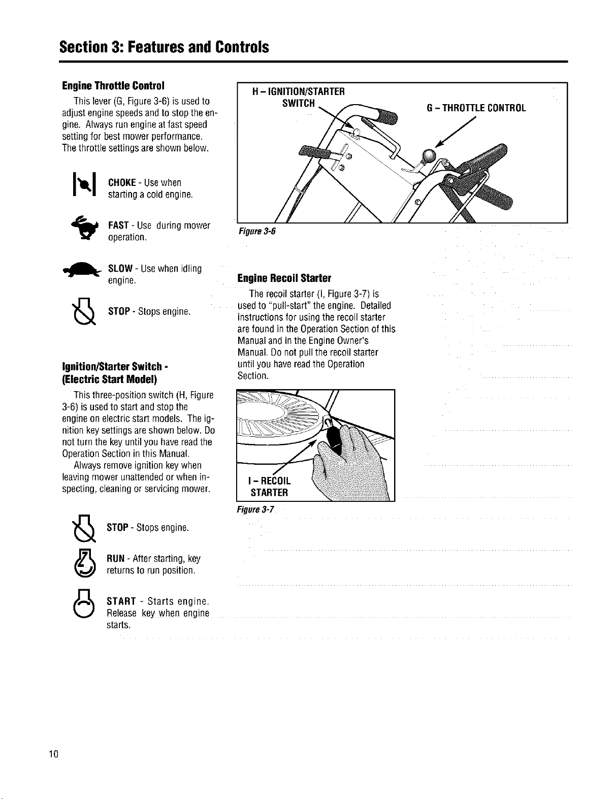
EngineThrottle Control
This lever(G, Figure3-6) isusedto
adjustenginespeedsandto stopthe en-
gine. Alwaysrun engineatfast speed
settingfor bestmower performance.
Thethrottlesettingsare shown below.
I_1 CHOKE-Usewhen
startinga coldengine.
H- IGNITION/STARTER
SWITCH
G- THROTTLECONTROL
FAST- Use duringmower
operation.
_ure3-6
m_It-SLOW- Usewhenidling
engine.
"_ STOP- Stopsengine.
Ignition/Starter Switch -
(Electric Start Model)
This three-positionswitch (H, Figure
3-6) is usedto startand stop the
engineon electricstart models. Theig-
nition keysettingsareshown below.Do
notturn the keyuntilyou havereadthe
OperationSectionin this Manual.
Alwaysremoveignition keywhen
leavingmower unattendedorwhenin-
specting,cleaningor servicingmower.
'_ STOP-Stopsengine.
(_ RUN- After starting, key
returnsto run position.
45
Engine Recoil Starter
Therecoilstarter(I, Figure3-7) is
usedto "pull-start" theengine. Detailed
instructionsfor usingtherecoilstarter
arefound in theOperationSectionof this
Manualand in the EngineOwner's
Manual.Do notpull the recoilstarter
untilyou havereadthe Operation
Section.
Figure3-7
,/
START - Starts engine.
Release key when engine
starts.
lO
Operation
Before operating mower, be sure to
readall safety, controlsand operating
instructions in this Manual and on
decalslocatedonmachine.
Severe personal injury or property
damagecould result if this instruction
isnotfollowed.
BEFOREOPERATINGMOWER
1. Pre-Operation Checklist
With the sparkplug wiredisconnected
from thespark plug,performthefollow-
ing checksand servicesbeforeeachuse:
1. ReviewSection1:"Safety"andSection
3, "FeaturesandControls"in this man-
ual. ReadtheseparateEngineOwner's
Manualprovidedwith the unit.
2.Checkunitfor looseor missinghard-
ware.Tightenor replaceasneeded.
3.With the uniton levelground,check
theengineoil levelaccordingto the
instructionsinthe EngineOwner's
Manual. Theoil levelshouldbe atthe
FULLmarkon thedipstick or upto the
top ofthe oil fill holeon engineswith-
out a dipstick.
4. Checkall leversfor freedomof move-
ment.Readjustor repairasneeded
beforestartingengine.
5.Checkthat all guardsandshieldsare
in placeand properlysecured.
6. inspecttheareato mowedandre-
moveanydebriswhich couldbe
pickedup andthrown bythe mower
blades.
7.Checkthat the mulchercoveris prop-
erly installedinthe dischargeopening
(seeinstructionsin this Section).
Removethe mulchercoverto usethe
side-dischargemowing feature.
8. Onelectricstart models,checkthat
all wiring connectionsare cleanand
tight.
9. Checktheair pressurein therear
tires (15-20PSI). Keeptires inflated
equally.
GASOLINEISHIGHLYFLAMMABLEAND
ITS VAPORSAREEXPLOSIVE.TOhelp
preventseverepersonalinjuryor prop-
ertydamage:
• Follow gasoline safety rules in
Section1: "Safety" of this Manualand
in the separate Engine Owner's
Manual.
• Neverremovethegasolinefill capor
oddfuel when indoorsor whenengine
is runningor still hot.Allow engineto
cool at least three (3) minutesbefore
refueling.
• Keep smokingmaterials, sparks or
flamesfar awayfromfuel tankandfuel
container.
• Store gasoline in an approvedfuel
containerandin a well-ventilatedarea.
Store it safelyoutof the reachof chil-
dren. Do notstore gasolinewhere va-
porsconreachon opensparkor flame
or where ignitionsourcesore present
(such as hot water or space heaters,
furnaces,clothesdryers,stoves,elec-
tric motors,etc.).
• Fill tankto 1/2"belowbottomoffiller
neckto allowfor fuel expansion.Wipe
up spilled gasoline immediately and
movemowerawayfromgasolinefumes
before starting engine. Securely re-
place caps on fuel tank and fuel
container.
10.
Removethefuel capand checkthe
levelof gasolineaccordingto the in-
structionsin the EngineOwner's
Manual.Cleanaroundfuel fill area
beforeremovingfuelcap. Donot
checkfuellevelor addfuelwhile in-
doorsor if engineis running or hot.
Allow engineto cool for three(3)
minutes. Fillthetank with fresh,
11.
cleanunleadedgasolinewitha mini-
mum octaneratingof 77. Leave1/2"
ofspacefor fuel expansion.Donot
mix oil with gasoline.Donot use
gasolinewhich containsMethanol.
Seethe EngineOwner'sManualfor
instructionsand precautionsregard-
ing theuseof gasolinesthat are
blendedwith alcoholsor ethers
(calledoxygenatedor reformulated
gasolines). Securelyreplacecapson
fuel tankandfuel container.
Attachspark plugwireto spark plug
after completingabovechecklist.
2. Set Mower Cutting Height
To avoidpersonalinjury, do notadjust
cutting heightwhile wheels or blades
are turning. Release all handlebar
controlsandwait for all motiontostop
beforeadjustingcuttingheight.
1. Releaseall controlsbeforeadjusting
thecutting height.
2. Adjustthecutting heightfrom 1 to4
inchesbyrotatingtheCuttingHeight
Control lever(Figure3-4) eitherclock-
wiseto raisethe heightor counterclock-
wiseto lowerthe height. Notethat ac-
tualcutting heightswill vary according
to grassand soilconditions. A decaland
pointeron the rightsideof the mower
deckindicatesthe heightsetting.
3. Inheavyor tall grass,it is usually
betterto makethefirst cut at a higher
settingandthen makea secondcut at
thedesiredheight. In rough terrain,a
highersetting is recommendedasit will
minimizethe chancesof the bladestrik-
ingtheground or hiddenobstructions.
11
Section4: Operation
3. Test Blade-Brake-Clutch
Central System
Themower isequippedwith a blade-
brake-clutchwhich isdesignedto stop
the mowerbladeswithin three(3)
secondsafter releaseofthe Operator
PresenceControl or theBladeDrive
Control. Nevertamperwith, or attempt
to defeatthe purposeofthis safety
device.
Thecontrol systemisa mechanical
devicewhich issubjectto wear.
Therefore,test theoperationofthe
blade-brake-clutchcontrol systembefore
eachuseof themower.Referto "Blade
BrakeControlTest"atthe endofthis
Section.
4. Select Mulching or Side-
Discharge Mowing
Beforeinstallingor removingmulching
cover, stop engine, wait for parts to
stopmoving,anddisconnectsparkplug
wire. Removeignition key on electric
startmodels.
Youcanusethe mowereitherasa
mulchingmower or asa side-discharge
mower. To usethe mulchingfeature,in-
sert the mulchercoveras described
below. Removethe mulchercoverto
side-dischargegrassclippings. The
mulchercoverisdesignedto keepthe
dischargechuteraisedup whilemowing.
Whenthe coveris removed,the dis-
chargechutewill loweritselffor side-
dischargemowing.
To installor removemulcher cover:
1. Stoptheengineand waitfor all parts
to stop moving. Disconnectthespark
plugwirefrom thespark plug.Remove
the ignitionkeyon electricstart models.
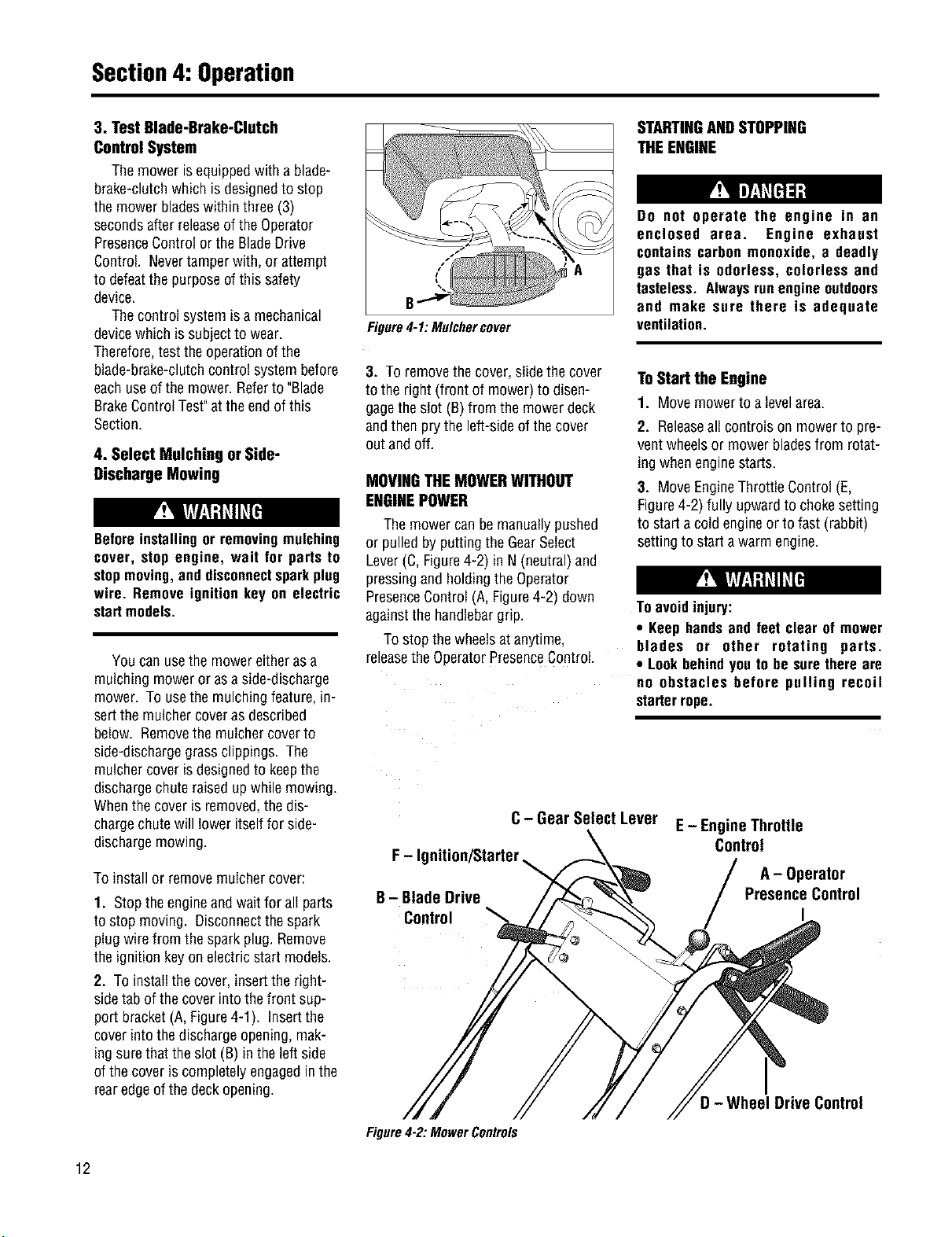
2. Toinstall thecover,insertthe right-
sidetabof thecover intothefront sup-
port bracket(A,Figure4-1). Insertthe
cover intothedischargeopening,mak-
ingsurethat theslot (B)in theleft side
of thecover iscompletelyengagedinthe
rearedgeof thedeckopening.
B
Figure4-1: Mulchercover
STARTINGANDSTOPPING
THEENGINE
Do not operate the engine in an
enclosed area. Engine exhaust
containscarbon monoxide, a deadly
gas that is odorless, colorless and
tasteless. Alwaysrunengineoutdoors
and make sure there is adequate
ventilation.
3. Toremovethe cover,slidethecover
to the right(front of mower)to disen-
gagetheslot (B)from the mowerdeck
andthen prythe left-sideof thecover
outand off.
MOVINGTHE MOWERWITHOUT
ENGINEPOWER
Themower canbe manuallypushed
or pulledby puttingthe GearSelect
Lever(C, Figure4-2) in N (neutral)and
pressingand holdingtheOperator
PresenceControl(A,Figure4-2) down
againstthehandlebargrip.
Tostop the wheelsatanytime,
releasetheOperatorPresenceControl.
ToStart the Engine
1. Movemowerto alevelarea.
2. Releaseall controls on mowerto pre-
ventwheelsor mower bladesfrom rotat-
ing whenenginestarts.
3. MoveEngineThrottleControl(E,
Figure4-2) fully upwardto chokesetting
to starta coldengineor to fast (rabbit)
settingto starta warm engine.
Toavoidinjury:
• Keephandsand feet clear of mower
blades or other rotating parts.
• Lookbehindyouto be surethere are
no obstacles before pulling recoil
starterrope.
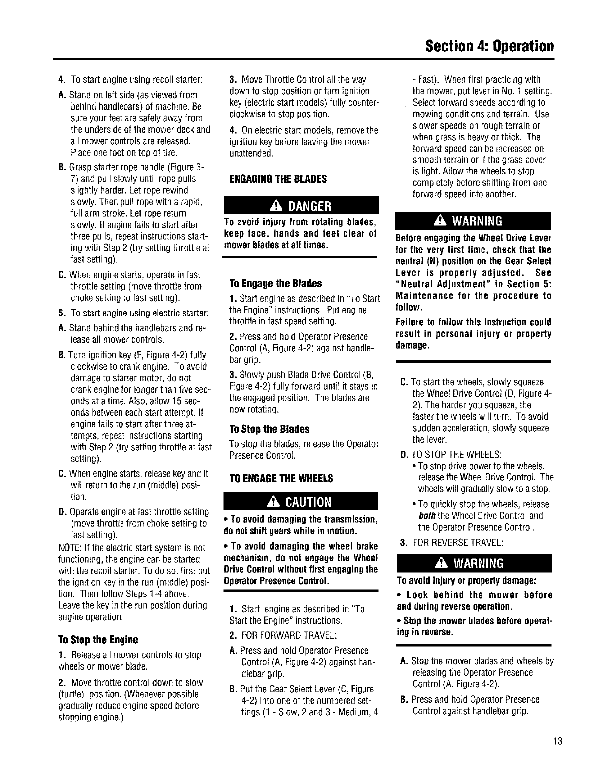
F-Ig
B- Blade Drive
Control
C- Gear Select Lever
E - Engine Throttle
Control
A- Operator
Presence Control
Figure4-2: MowerControls
D- Wheel Drive Control
12
Section4: Operation
4. To startengineusingrecoilstarter:
A. Standon leftside(asviewedfrom
behindhandlebars)of machine.Be
sureyour feetaresafelyawayfrom
the undersideof the mowerdeckand
all mowercontrolsare released.
Placeonefoot ontop of tire.
B. Graspstarterrope handle(Figure3-
7) andpull slowly until ropepulls
slightly harder.Letroperewind
slowly. Thenpull ropewith a rapid,
full arm stroke. Letropereturn
slowly. Ifenginefails to startafter
threepulls, repeatinstructionsstart-
ingwith Step2 (try settingthrottle at
fast setting).
C. Whenenginestarts,operatein fast
throttle setting(movethrottle from
chokesettingto fastsetting).
5. To startengineusingelectricstarter:
A. Standbehindthe handlebarsand re-
leaseall mower controls.
B.Turnignition key (F,Figure4-2) fully
clockwiseto crank engine.To avoid
damageto startermotor,do not
crankenginefor longerthanfive sec-
ondsat a time.Also,allow 15sec-
onds betweeneachstart attempt.If
enginefails to startafterthreeat-
tempts, repeatinstructionsstarting
with Step2 (try settingthrottle atfast
setting).
C. Whenenginestarts,releasekeyandit
will returntotherun (middle)posi-
tion.
D. Operateengineat fastthrottle setting
(movethrottle from chokesettingto
fast setting).
NOTE:If theelectricstartsystemis not
functioning,the enginecanbestarted
with the recoilstarter.Todo so, first put
the ignitionkeyin the run (middle)posi-
tion. Thenfollow Steps1-4 above.
Leavethe keyin therun positionduring
engineoperation.
ToStop the Engine
1. Releaseall mowercontrolsto stop
wheelsor mower blade.
2. Movethrottle controldownto slow
(turtle) position.(Wheneverpossible,
graduallyreduceenginespeedbefore
stoppingengine.)
3. MoveThrottle Controlall theway
downto stop position or turn ignition
key(electricstart models)fully counter-
clockwiseto stop position.
4. Onelectricstart models,removethe
ignition keybeforeleavingthemower
unattended.
ENGAGINGTHEBLADES
To ovoid injuryfrom rotatingblades,
keep face, hands and feet clear of
mowerbladesat all times.
ToEngagethe Blades
1. Start engineasdescribedin "ToStart
the Engine"instructions. Putengine
throttle infast speedsetting.
2. Pressandhold OperatorPresence
Control(A,Figure4-2) againsthandle-
bargrip.
3. Slowly pushBladeDriveControl(B,
Figure4-2) fully forward until it staysin
the engagedposition. The bladesare
nowrotating.
ToStop the Blades
To stopthe blades,releasetheOperator
PresenceControl.
TOENGAGETHEWHEELS
• To avoiddamagingthetransmission,
donotshiftgearswhilein motion.
• To avoid damagingthe wheel brake
mechanism,do not engagethe Wheel
DriveControlwithoutfirstengagingthe
OperatorPresenceControl.
1. Start engineasdescribedin "To
Startthe Engine"instructions.
2. FORFORWARDTRAVEL:
A. Pressand hold OperatorPresence
Control (A,Figure4-2) againsthan-
dlebargrip.
B. Putthe GearSelectLever(C,Figure
4-2) intoone ofthe numberedset-
tings (1 - Slow,2and 3 - Medium,4
- Fast).Whenfirst practicingwith
themower,put leverin No.1 setting.
Selectforward speedsaccordingto
mowing conditionsand terrain. Use
slowerspeedson roughterrainor
whengrassis heavyor thick. The
forward speedcanbe increasedon
smoothterrainor ifthe grasscover
is light. Allowthewheelsto stop
completelybeforeshiftingfrom one
forward speedintoanother.
BeforeengagingtheWheel DriveLever
for the very first time, checkthat the
neutral(N) positionon the GearSelect
Lever is properly adjusted. See
"Neutral Adjustment" in Section 5:
Maintenance for the procedure to
follow.
Failureto follow this instructioncould
result in personal injury or property
damage.
C.Tostartthe wheels,slowlysqueeze
theWheelDriveControl(D, Figure4-
2).Theharderyou squeeze,the
fasterthe wheelswill turn. Toavoid
suddenacceleration,slowlysqueeze
thelever.
O.TOSTOPTHEWHEELS:
•Tostop drivepowerto thewheels,
releasetheWheelDriveControl. The
wheelswill graduallyslowto astop.
•To quicklystop thewheels,release
boththeWheelDriveControland
the OperatorPresenceControl.
3. FORREVERSETRAVEL:
Toavoidinjuryorpropertydamage:
• Look behind the mower before
andduringreverseoperation.
• Stopthemowerbladesbeforeoperat-
ingin reverse.
A. Stopthe mowerbladesandwheelsby
releasingthe OperatorPresence
Control(A,Figure4-2).
B. Pressand holdOperatorPresence
Controlagainsthandlebargrip.
13
Section4: Operation
C. Putthe GearSelectLever(C, Figure
4-2) in R(reverse)settingbyfirst
movingleverto N(neutral). Then
pull leverup,turn itto Rposition,
andreleaselever.
D.To startthewheels,slowlysqueeze
WheelDriveControl(D, Figure4-2).
To avoidsuddenacceleration,slowly
squeezethe lever.
E.TOSTOPTHEWHEELS:
•Tostop drivepowerto thewheels,
releasetheWheelDriveControl.The
wheelswill graduallyslowto astop.
•To quicklystop thewheels,release
boththeWheelDriveControland
the OperatorPresenceControl.
• ReturntheGearSelectLeverto the
N(neutral)positionwhenyouhave
completedreverseoperation. Allow
thewheelsto stop completelybe-
fore shiftingfrom R(reverse)intoa
forward speed.
Themowerturns easilybypushing
the handlebarsin theoppositedirection
thatyou want to turn.Thedifferential
mechanisminsidethetransaxlewill
allowthe insideturning wheelto stop or
slow downwhiletheoutsideturning
wheelis poweredbythe drivesystem.
Reducethewheelspeedbeforeturn-
ingthe mower.Fortight turns, disen-
gagethe WheelDriveControland manu-
ally pushthe mowerthroughtheturn (if
needed,putthe GearSelectLeverin
neutralsothewheelsturnfreely).
MOWINGTIPSANDHINTS
Toavoidinjuryorpropertydamage:
• Before mowing, thoroughly inspect
area where mower is to be used and
remove all stones, sticks, wires,
bones,nailsandotherforeignobjects.
• Disengage mower blades before
crossinggravel drives, roads,or side-
walksto preventbladesfrom throwing
stonesorotherhazardousobjects.
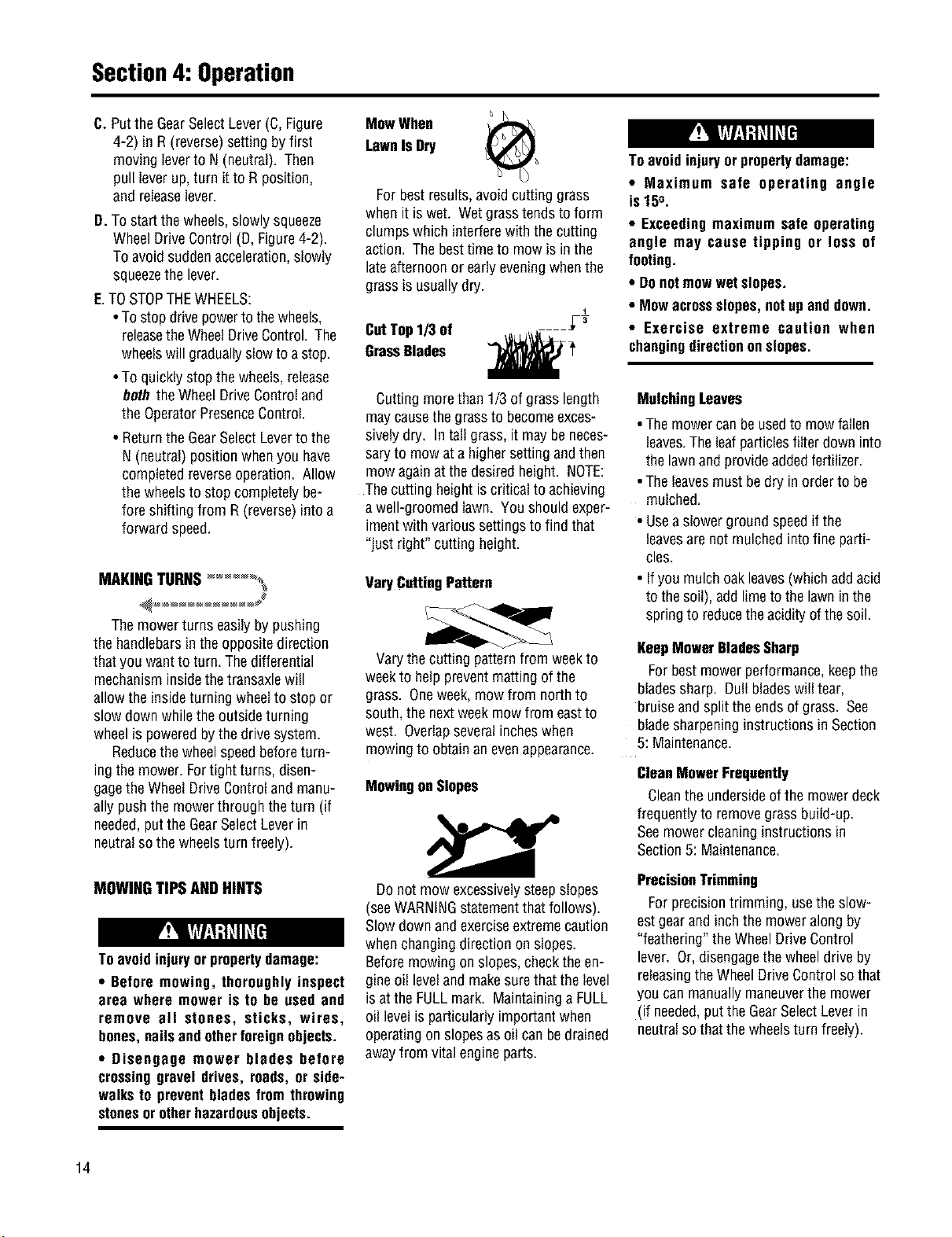
MowWhen
LawnIsDry
Forbestresults,avoidcuttinggrass
whenit is wet. Wetgrasstends toform
clumpswhich interferewith thecutting
action. Thebesttimeto mowis in the
lateafternoonor earlyeveningwhenthe
grassis usuallydry.
CutTop1/3 of
GrassBlades
Cuttingmorethan 1/3of grass length
maycausethegrassto becomeexces-
sivelydry. Intall grass,it maybe neces-
saryto mowata highersettingandthen
mow againatthedesiredheight. NOTE:
Thecutting heightiscritical to achieving
a well-groomedlawn. Youshouldexper-
imentwith varioussettingsto find that
"just right" cuttingheight.
VaryCuttingPattern
Varythecutting patternfrom weekto
weekto helppreventmattingofthe
grass. Oneweek,mowfrom northto
south,the nextweek mowfrom eastto
west. Overlapseveralincheswhen
mowingto obtainan evenappearance.
MowingonSlopes
Donot mow excessivelysteepslopes
(seeWARNINGstatementthat follows).
Slowdownand exerciseextremecaution
whenchangingdirectionon slopes.
Beforemowing on slopes,checktheen-
gineoil leveland makesurethat thelevel
is attheFULLmark. Maintaininga FULL
oil levelis particularlyimportantwhen
operatingon slopesasoil can bedrained
awayfrom vitalengineparts.
Toavoidinjuryorpropertydamage:
• Maximum safe operating angle
is 150.
• Exceedingmaximum safe operating
angle may cause tipping or loss of
footing.
• Donotmowwetslopes.
• Mowacrossslopes,notupanddown.
• Exercise extreme caution when
changingdirectiononslopes.
MulchingLeaves
• Themowercanbe usedto mowfallen
leaves.Theleafparticlesfilter downinto
the lawnandprovideaddedfertilizer.
•Theleavesmustbe dry inorder to be
mulched.
• Usea slowerground speedif the
leavesarenotmulchedintofine parti-
cles.
• Ifyou mulch oakleaves(whichaddacid
to thesoil), addlimetothe lawninthe
springto reducetheacidityof thesoil.
KeepMowerBladesSharp
Forbestmower performance,keepthe
bladessharp. Dullbladeswilltear,
bruiseand split theendsof grass. See
bladesharpeninginstructionsin Section
5: Maintenance.
CleonMowerFrequently
Cleanthe undersideofthe mowerdeck
frequentlyto removegrassbuild-up.
Seemower cleaninginstructionsin
Section5: Maintenance.
PrecisionTrimming
Forprecisiontrimming, usethe slow-
estgearand inchthe moweralong by
"feathering"theWheelDriveControl
lever. Or,disengagethe wheeldrive by
releasingtheWheelDriveControlso that
youcanmanuallymaneuverthe mower
(if needed,put theGearSelectLeverin
neutralsothat thewheelsturn freely).
14
Section4: Operation
BLADEBRAKECONTROLTEST
Whenthe OperatorPresenceControl
isreleasedduring operationofthe
mower,theenginedoesnot stop,but
the bladesshouldstop within three(3)
seconds. Thefollowing test providesa
visualtest ofwhetherthe BladeBrake
ControlSystemisfunctioning. Perform
this test beforeeachuseofthe mower.
1. Parkmoweron a portionof lawn
which hasnot beenrecentlymowed.
2. Setthe cuttingheightsothe mower
cuts 1/3of thegrassheight.
To avoid personal injury or property
damage,make surethat the moweris
ongrass,andthatthetest area isclear
of foreignobjectsand bystandersbe-
foreyou beginthe BladeBrakeControl
Test.
If the OperatorPresenceControlor the
Blade Drive Controlare not adjusted
correctly,the bladesmay continueto
rotate after release of the Operator
PresenceControl. If the bladesdo not
stopwithinthree(3) secondsofrelease
ofthe OperatorPresenceControl,move
the EngineThrottleControltothe STOP
position, disconnect the spark plug
wire, andmovethewire awayfromthe
sparkplug. Do not operatethe mower
until the Blade Brake ControlSystem
hasbeenrepaired.
Failure to do this couldresult in per-
sonalinjuryor propertydamage.
3. Starftheengine.
4. Pressthe OperatorPresenceControl
downagainstthe handlebargrip and
pushthe BladeDriveControlfully for-
warduntil it staysin theengagedposi-
tion.
5. Putthe GearSelectLeverinthe No.
setting.
6. Engagethe wheelswith theWheel
DriveControlanddrivethe mowerfor
severalfeet. ThenreleasetheOperator
PresenceControl.
A. Lookatthelawnjust mowed.The
lawnshouldbe cut upto thepoint
wherethe OperatorPresenceControl
was released.
B. Pressthe OperatorPresenceControl
againstthe handlebargrip but DO
NOTre-engagethe BladeDrive
Control. Drivethe mowerforward
for severalmorefeet. Releasethe
OperatorPresenceControlandlook
atthe lawn.Thegrassshould NOT
havebeencut. This indicatesthat
the OperatorPresenceControlhas
disengagedthebladedriveand
stoppedtheblades.
7. If the mowercutsthegrass in Step
6-B,theOperatorPresenceControlis
NOTdisengagingthebladedrive.
Immediatelystoptheengine,discon-
nectthesparkplugwire,andmovethe
wireawayfromthesparkplug.
8. Donot usethemower untilthe Blade
BrakeControlSystemhasbeenin-
spected,adjustedor repairedbyan au-
thorizeddealer.
15
Maintenance
_ eforeinspecting,cleaningorservicingthemachine,shutoffengine,waitformovingpartstostop,disconnectspark
plugwireandmovewireawayfromsparkplug.Removeignitionkey(electricstartmodels).
Failuretofollowtheseinstructionscanresultinseriouspersonalinjup/orpropertydamage.
Carefully read this Section on mower
and engine maintenance and service.
Performing the required maintenance
according to schedule will ensure the
properperformanceand long lifeof your
machine.
Beforeinspecting,cleaningorservicing
the machine, shut off engine, make
surethatall movingpartshavecometo
a completestop,disconnectsparkplug
wire and movewire away from spark
plug. Removeignition key on electric
startmodels.
Failureto followtheseinstructionscan
result in personal injury or property
damage.
NOTE: All referencesto left, right, front
andrearofthemachinearedeterminedby
standingbehindthehandlebarsandfacing
thedirectionoffon_ardtravel.
IMPORTANT:REFERTO
MAINTENANCECHARTINTHIS
SECTIONFORALISTINGOFREGU-
LARLYSCHEDULEDMAINTENANCE
PROCEDURES,
ENGINESERVICE
Routineengineserviceis described
below. Formorecompleteengineser-
viceinformation, referto theengine
manualprovidedwith your machine.
Forcompleteengineservice,contactan
authorizedenginedealer.
ENGINEOIL
OILLEVEL:With moweron level
ground,the engineoil levelmust bebe-
tweenthe "ADD"and "FULL"markson
the dipstickatall times. Checkbefore
eachuseandevery5 operatinghours.
OILCHANGE:Ona newengine,change
oil afterfirst 2 hoursof use,thenchange
oil regularlyasspecifiedon the
MaintenanceChart. Referto Engine
Owner'sManualfor oil capacity.
OILTYPE:Useclean,high qualitydeter-
gentoil havingan A.P.I.serviceclassifi-
cationof SE,SFor SG. Usenospecia!
additiveswith oil. Referto theEngine
Owner'sManualfor recommendedSAE
viscosity gradesthat matchthe starting
temperatureanticipatedbeforethe next
oil change.
CheckingOilLevel:
1. Parkmachineon levelground.
2. Stopengine,waitforpartstostop
moving,anddisconnectsparkplug
wire.
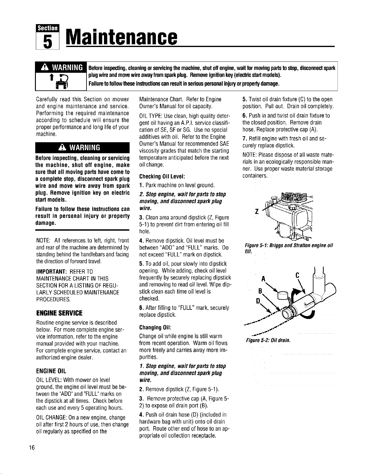
3. Cleanareaaround dipstick (Z, Figure
5-1) to preventdirtfrom enteringoil fill
hole.
4. Removedipstick. Oillevelmustbe
between"ADD"and "FULL"marks. Do
notexceed"FULL"markon dipstick.
5. Toaddoil, pourslowly intodipstick
opening. Whileadding,checkoil level
frequentlybysecurelyreplacingdipstick
and removingto readoil level.Wipedip-
stickcleaneachtime oil levelis
checked.
6. Afterfilling to "FULL"mark,securely
replacedipstick.
ChangingOil:
Changeoil while engineisstill warm
from recentoperation. Warmoil flows
morefreelyandcarriesawaymoreim-
purities.
1.Stopengine,waitforpartstostop
moving,anddisconnectsparkplug
wire.
2. Removedipstick (Z, Figure5-1).
3. Removeprotectivecap (A,Figure5-
2) to exposeoil drain port (B).
4. Pushoil drain hose(D)(includedin
hardwarebagwith unit) ontooil drain
port. Routeotherendof hoseto anap-
propriateoil collectionreceptacle.
5. Twist oil drain fixture (C)to theopen
position. Pullout. Drainoil completely.
6. Pushin andtwist oil drain fixtureto
the closedposition. Removedrain
hose.Replaceprotectivecap(A).
7. Refill enginewith fresh oil andse-
curely replacedipstick.
NOTE:Pleasedisposeofall wastemate-
rials inan ecologicallyresponsibleman-
ner. Useproperwastematerialstorage
containers.
Figure5-1:BriggsandStrattonengineoil
fill.
Figure5-2:Oildrain.
16
Section5: Maintenance
_ eforeinspecting,cleaningorservicingthemachine,shutoffengine,waitformovingpartstostop,disconnectspark
plugwireandmovewireawayfromsparkplug.Removeignitionkey(electricstartmodels).
FailuretofollowtheseinslnJctionscanresultinseriouspersonalinjur/orpropertydamage.
ENGINECLEANING
• Stopengine,waitforpartstostep
moving,disconnectsparkplug wire,
andallowenginetocoolbeforein-
spectingorcleaningengine.
• Dailyor moreoften,beforerunningen-
gine,removegrassandchafffrom recoil
fingerguardor rotatingscreento prevent
enginedamagecausedbyoverheating.
Alsokeepcoolingvanes,governorlink-
age,springsandcontrolsfreeofdebris.
• Dailyor moreoften, beforerunningen-
gine,cleanmufflerarea(be suremuffler
iscool)to removeall grassandcom-
bustibledebris. If engineis equipped
with a sparkarrestorscreen,removeas-
semblyevery50 hoursfor cleaningand
inspection.Replaceifdamaged.
• Grassor chaff mayclogengine'sair
coolingsystem,especiallyafter pro-
longedoperationcutting tall, dE/grass.
SeeEngineOwner'sManualfor instruc-
tions on cleaningunderneaththeengine
blowerhousing.
AIR CLEANERSERVICE
Improperair cleanermaintenancecan
causeenginedamage.Referto the
EngineOwner'sManualfor morecom-
pleteair cleanerserviceinformation.
SERVICESCHEDULE:
Outerfoam pre-cleaner- washand re-oil
every25 operatinghoursor everysea-
son, whicheveroccursfirst.
innerpapercartridge- cleanor replace
every100operatinghoursor everysea-
son, whicheveroccursfirst.
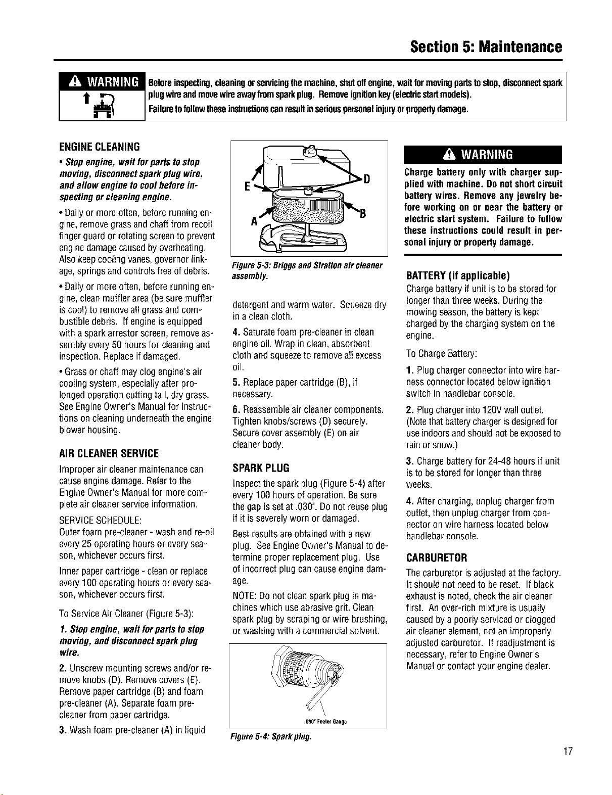
ToServiceAir Cleaner(Figure5-3):
1. Stopengine,waitfor partsto stop
moving,anddisconnectsparkplug
wire.
2. Unscrewmountingscrewsand/or re-
moveknobs(D). Removecovers(E).
Removepapercartridge(B) andfoam
pre-cleaner(A).Separatefoam pre-
cleanerfrom papercartridge.
3. Washfoam pre-cleaner(A) in liquid
Figure5-3: BriggsandStrattonair cleaner
assembly.
detergentandwarm water. Squeezedry
in a cleancloth.
4. Saturatefoam pre-cleanerin clean
engineoil. Wrapin clean,absorbent
clothand squeezeto removeall excess
oil.
5. Replacepapercartridge (B),if
necessary.
6. Reassembleair cleanercomponents.
Tighten knobs/screws(D) securely.
Securecoverassembly(E)on air
cleanerbody.
SPARKPLUG
Inspectthespark plug(Figure5-4) after
every100 hoursof operation.Besure
the gap issetat .030".Donot reuseplug
if it is severelyworn or damaged.
Bestresultsare obtainedwith a new
plug. SeeEngineOwner'sManualto de-
termine proper replacementplug. Use
of incorrectplugcancauseenginedam-
age.
NOTE:Donot cleansparkplugin ma-
chineswhich useabrasivegrit. Clean
sparkplug byscrapingor wire brushing,
or washingwith a commercialsolvent.
\
.030"l:eeler Gauge
Figure5-4:Sparkplug.
Charge batteryonlywith chargersup-
plied withmachine.Donotshortcircuit
batterywires. Removeany jewelry be-
fore workingon or near the battery or
electricstartsystem. Failureto follow
these instructionscouldresult in per-
sonalinjuryor propertydamage.
BATTERY(if applicable)
Chargebatteryif unit is to bestoredfor
longerthanthreeweeks.Duringthe
mowingseason,the batteryiskept
chargedbythe chargingsystemonthe
engine.
To ChargeBattery:
1. Plugchargerconnectorintowire har-
nessconnectorlocatedbelowignition
switch inhandlebarconsole.
2. Plugchargerinto120Vwalloutlet.
(Notethatbatterychargerisdesignedfor
useindoorsandshouldnot beexposedto
rainor snow.)
3. Chargebatteryfor 24-48 hours if unit
isto be storedfor longerthanthree
weeks.
4. Aftercharging,unplugchargerfrom
outlet,then unplugchargerfrom con-
nectoronwire harnesslocatedbelow
handlebarconsole.
CARBURETOR
Thecarburetor isadjustedat thefactory.
It shouldnot needto bereset. If black
exhaustis noted,checktheair cleaner
first. An over-rich mixtureis usually
causedbya poorlyservicedor clogged
air cleanerelement,notan improperly
adjustedcarburetor. If readjustmentis
necessary,referto EngineOwner's
Manualor contactyour enginedealer.
17
Section5: Maintenance
I
_ eforeinspecting,cleaningorservicingthemachine,shutoffengine,waitformovingpartstostop,disconnectsparkI
plugwireendmovewireawayfromsparkplug.Removeignitionkey(electricstartmodels).
Fa uretofo owthesenslructonscanresult nseronspersonanup/orpropertydamage.
ENGINESTORAGE Thebeltcover mustbe removedto per- 5. Loosenfour mounting bolts (L) se-
form severalmaintenanceprocedures, curing spindlehousing (beneathmower
To RemoveBeltCover: deck)to mowerdeck.
If enginewill be unusedfor 30 daysor
more,prepareitfor storagebyfollowing
therecommendedproceduresfound in
theEngineOwner'sManual.
MOWERSERVICE
Thefollowing maintenance/repairproce-
durescan beperformedbyeitherthe
owneror anauthorizedservicedealer.
Seeanauthorizedservicedealerfor
completemowerservice.
1.Stopengine,waitforall partsto
stopmoving,anddisconnectspark
plug wire.
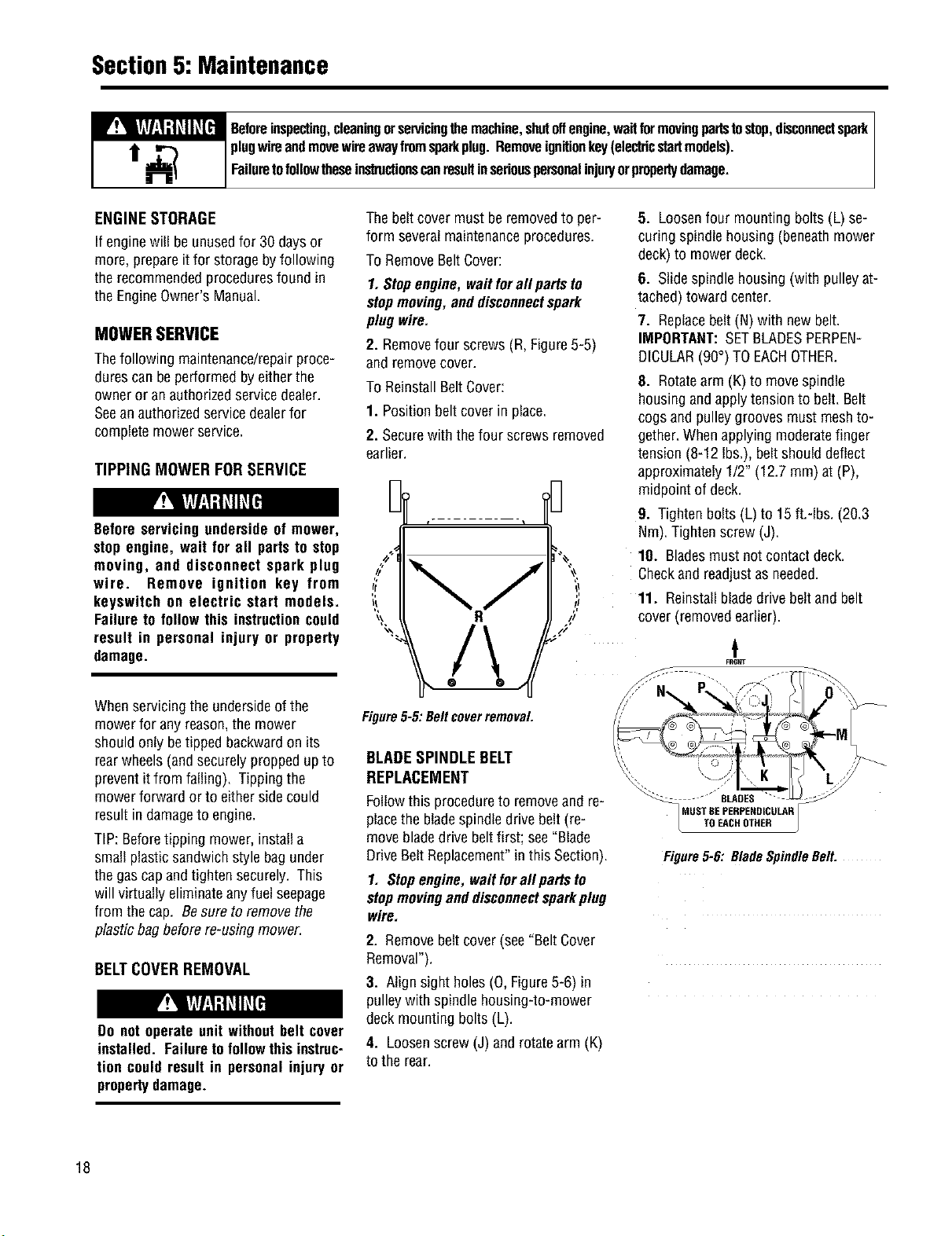
2. Removefour screws (R,Figure5-5)
and removecover.
To ReinstallBeltCover:
1. Positionbelt coverin place.
2. Securewith thefour screwsremoved
earlier.
TIPPING MOWERFOR SERVICE
Beforeservicingunderside of mower,
stop engine, wait for ell partsto stop
moving, end disconnect spark plug
wire. Remove ignition key from
keyswitch on electric start models.
Failureto followthis instructioncould
result in personal injury or property
damage.
Whenservicingthe undersideof the
mowerfor anyreason,the mower
shouldonlybetipped backwardon its
rearwheels(andsecurelyproppedupto
preventitfrom failing). Tippingthe
mowerforward or to eithersidecould
result in damageto engine.
TIP: Beforetipping mower,installa
small plasticsandwichstyle bagunder
thegascapandtighten securely. This
will virtuallyeliminateanyfuel seepage
from thecap. Besureto removethe
plasticbagbeforere-usingmower.
BELTCOVERREMOVAL
Do not operateunit withoutbelt cover
installed. Failuretofollowthis instruc-
tion couldresult in personalinjury or
propertydamage.
Figure5-5: Beltcoverremoval
BLADESPINDLE BELT
6. Slidespindlehousing(with pulleyat-
tached)toward center.
7. Replacebelt(N)with newbelt.
IMPORTANT:SETBLADESPERPEN-
DICULAR(90°)TOEACHOTHER.
8. Rotatearm(K) to movespindle
housingandapplytensionto belt. Belt
cogs andpulleygroovesmust meshto-
gether.Whenapplyingmoderatefinger
tension (8-12 Ibs.),beltshoulddeflect
approximately1/2" (12.7mm) at (P),
midpointof deck.
9. Tightenbolts (L) to 15 ft.-Ibs. (20.3
Nm).Tightenscrew(J).
10. Bladesmustnot contactdeck.
Checkand readjustas needed.
11. Reinstallbladedrive beltandbelt
cover (removedearlier).
REPLACEMENT
Followthis procedureto removeand re-
placethe bladespindledrivebelt(re-
movebladedrive beltfirst; see"Blade
DriveBeltReplacement"inthis Section).
1. Stopengine,waitforall partsto
stopmovinganddisconnectsparkplug
wire.
2. Removebeltcover(see"BeltCover
Removal").
3. Align sight holes(0, Figure5-6) in
pulleywith spindlehousing-to-mower
deck mountingbolts (L).
4. Loosenscrew(J) and rotatearm (K)
to the rear.
"""- _ "''BLADES "
MUSTBEPEHPEHDICULAR
TOEACHOTHER
Figure5-6: BladeSpindleBelt.
18
Section5: Maintenance
_ eforeinspecting,cleaningorservicingthemachine,shutoffengine,waitformovingpartstostop,disconnectspark
plugwireandmovewireawayfromsparkplug.Removeignitionkey(electricstartmodels).
Failuretofollowtheseinslructionscanresultinseriouspersonalinjup/orpropertydamage.
BLADEDRIVEBELT
REPLACEMENT
Followthis procedureto removeand re-
placethe bladedrivebelt. Anassistant
will beneeded.
ToRemoveBelt:
1. Stopengine,waitforall partsto
stopmoving,anddisconnectspark
plugwire.
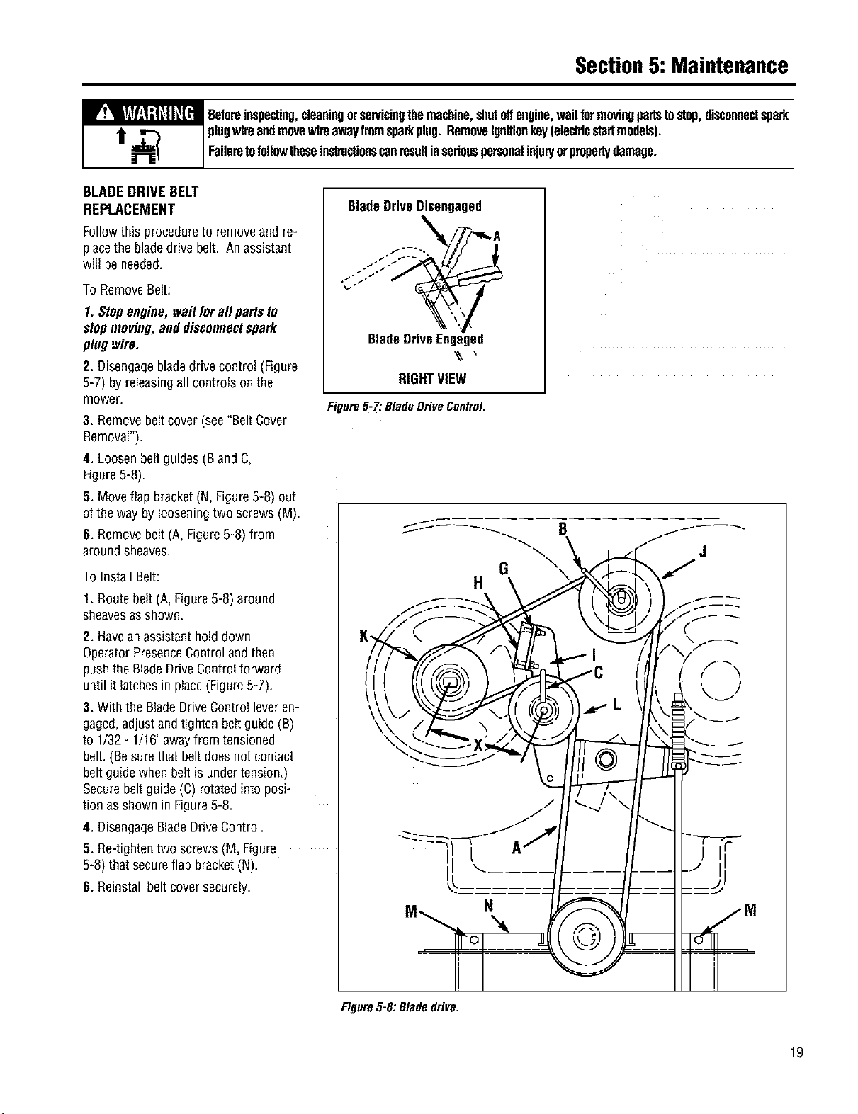
2. Disengagebladedrivecontrol (Figure
5-7) byreleasingall controls on the
mower.
3. Removebeltcover (see"BeltCover
Removal").
4. Loosenbeltguides(B and C,
Figure5-8).
5. Moveflap bracket(N, Figure5-8) out
of theway bylooseningtwo screws (M).
8. Removebelt(A, Figure5-8) from
aroundsheaves.
ToInstall Belt:
1, Routebelt (A,Figure5-8) around
sheavesasshown.
2. Havean assistanthold down
OperatorPresenceControlandthen
pushtheBladeDriveControlforward
untilit latchesin place(Figure5-7).
3. With the BladeDriveControlleveren-
gaged,adjustandtighten beltguide (B)
to 1/32- 1/16"awayfrom tensioned
belt.(Besurethat beltdoesnotcontact
beltguidewhenbelt is undertension.)
Securebeltguide(C) rotatedinto posi-
tion asshown in Figure5-8.
4. DisengageBladeDriveControl.
5. Re-tightentwo screws(M, Figure
5-8) that secureflap bracket(N).
6. Reinstallbeltcoversecurely.
BladeDriveDisengaged
\
BladeDriveEngaged
\\ ,
RIGHTVIEW
Figure5-7: BladeDrive Control.
\ J
G \
H
Figure5-8: Bladedrive.
19
Section5: Maintenance
_ eforeinspecting,cleaningorservicingthemachine,shutoffengine,waitformovingpartstostop,disconnectspank
plugwireandmovewireawayfromspankplug.Removeignitionkey(electricstartmodels).
Failuretofollowtheseinstructionscanresultinseriouspersonalinjur/orpropertydamage.
BLADEBRAKEREPLACEMENT
Followthis procedureto installa new
bladebrake.
ToRemoveBladeBrake:
1. Stopengine,waitforall partsto
stopmoving,anddisconnectspark
plugwire.
2. Removebeltcoverasdescribedin
"Belt CoverRemoval"instructions.
3. Removehardware(G,Figure5-8)
securingbladebrake(H).
4. Removeold brake(H)from idler
arm (I).
ToInstall Brake:
1. Positionnewbrake(H) in placeon
idlerarm (I).
2. Centerbrakein sheavegrooveand
securebrake(H)with hardware(G)re-
movedearlier.
3. Reinstallbeltcoversecurely.
4. Testoperationof bladebrake(see
"BladeBrakeControlTest" in Operation
section).
BLADEDRIVEBELT
ADJUSTMENT
If thebladedrive beltis slippingdueto
lackof belttension,follow thesteps
below.
1. Stopengine,waitforall partsto
stopmoving,anddisconnectspark
plugwire.
2. Removebeltcoverasdescribedin
"Belt CoverRemoval"instructions.
3. With moweron levelground,adjust
bladecutting heightatabout3" (mea-
surefrom ground to flat portion of
blade).
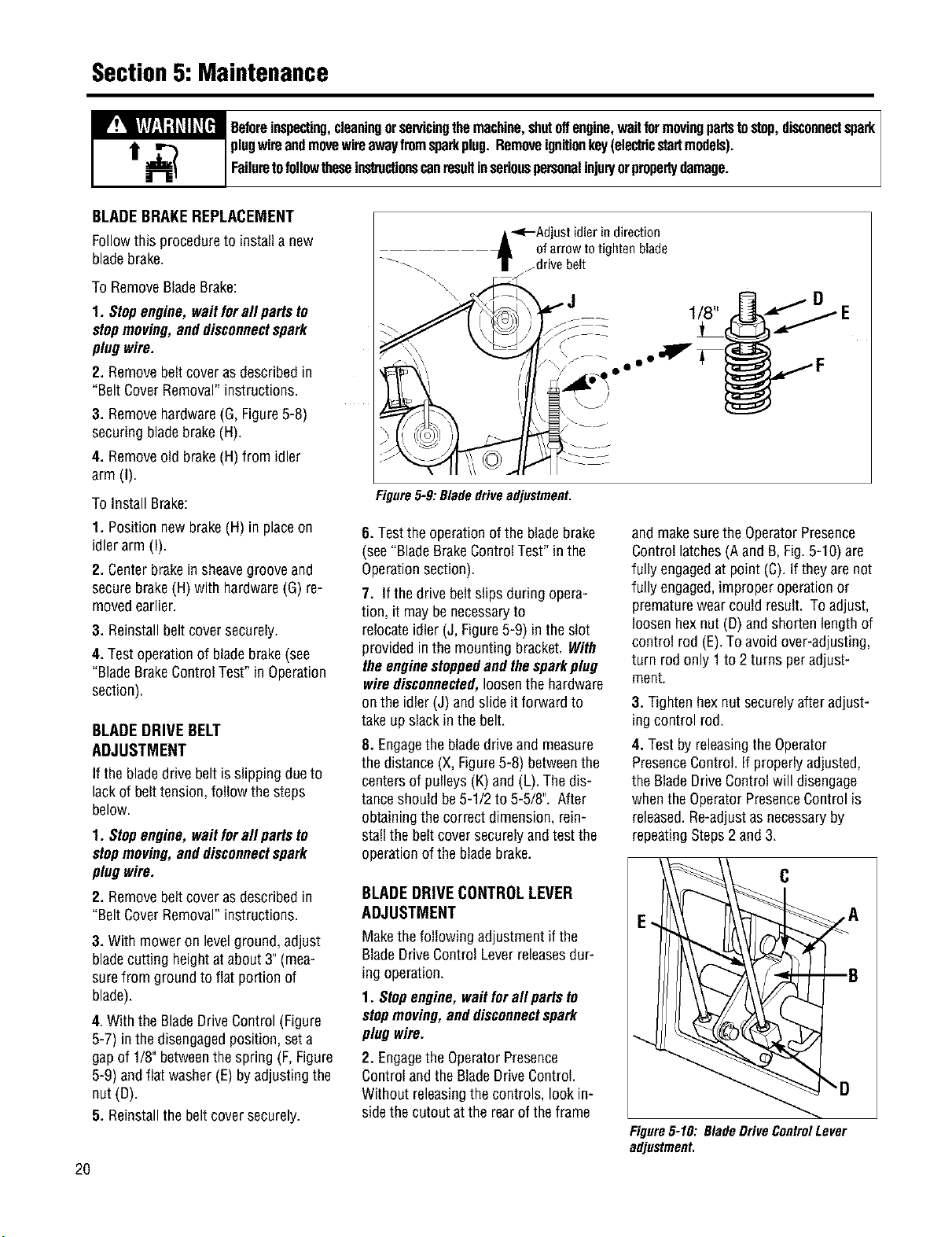
4. Withthe BladeDriveControl(Figure
5-7) inthedisengagedposition,seta
gapof 1/8" betweenthespring (F,Figure
5-9) andflat washer(E)byadjustingthe
nut(D).
5. Reinstallthe beltcoversecurely.
2O
-_--Adjust idlerin direction
of arrow to tighten blade
f drive belt
D
Figure5-9: Bladedriveadjustment.
6. Testthe operationofthe bladebrake
(see"BladeBrakeControlTest"in the
Operationsection).
7. If thedrive beltslips during opera-
tion, it maybenecessaryto
relocateidler (J, Figure5-9) intheslot
providedinthe mountingbracket. With
theenginestoppedandthesparkplug
wiredisconnected,loosenthehardware
onthe idler (J) andslideit forward to
take upslackinthe belt.
8. Engagethe bladedriveand measure
the distance(X,Figure5-8) betweenthe
centersof pulleys(K) and(L). Thedis-
tanceshould be5-1/2to 5-5/8". After
obtainingthecorrect dimension,rein-
stallthe beltcoversecurelyandtestthe
operationofthe bladebrake.
BLADEDRIVECONTROLLEVER
ADJUSTMENT
Makethefollowing adjustmentif the
BladeDriveControl Leverreleasesdur-
ing operation.
1. Stopengine,waitforall partsto
stopmoving,anddisconnectspark
plugwire.
2. Engagethe OperatorPresence
ControlandtheBladeDriveControl.
Withoutreleasingthe controls, lookin-
sidethe cutoutatthe rearof theframe
and makesurethe OperatorPresence
Controllatches(Aand B,Fig.5-10) are
fully engagedat point (C).If they arenot
fully engaged,improperoperationor
prematurewearcould result. To adjust,
loosenhexnut (D)andshorten lengthof
control rod(E).Toavoidover-adjusting,
turn rodonly 1 to 2 turns peradjust-
ment.
3. Tighten hexnutsecurelyafter adjust-
ingcontrol rod.
4. Testby releasingtheOperator
PresenceControl.If properlyadjusted,
the BladeDriveControlwill disengage
whentheOperatorPresenceControlis
released.Re-adjustasnecessaryby
repeatingSteps2 and3.
Figure5-10: BladeDriveControlLever
adjustment.
Section5: Maintenance
_ eforeinspecting,cleaningorservicingthemachine,shutoffengine,waitformovingpartstostop,disconnectspark
plugwireandmovewireawayfromsparkplug.Removeignitionkey(electricstartmodels).
Failuretofollowtheseinstructionscanresultinseriouspersonalinjup/orpropertydamage.
WHEELDRIVE BELT
REPLACEMENT
Followthis procedureto replacethe
wheeldrive belt.
1. Stopengine,waitforall partsto
stopmoving,anddisconnectspark
plugwire.
2. Releaseall mower controls.
3. Removebeltcoverasdescribedin
"Belt CoverRemoval"instructions.
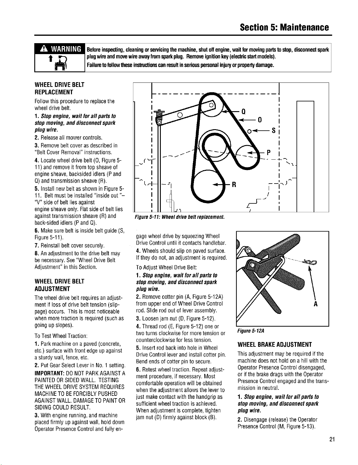
4. Locatewheeldrivebelt (0, Figure5-
11)and removeit from top sheaveof
enginesheave,backsidedidlers(P and
Q)and transmissionsheave(R).
5. Installnewbeltasshown in Figure5-
11. Beltmust beinstalled"insideout "-
"V" sideof belt liesagainst
enginesheaveonly.Flatsideof belt lies
againsttransmissionsheave(R)and
back-sidedidlers(Pand Q).
6. Makesurebelt isinsidebeltguide (S,
Figure5-11).
7. Reinstallbeltcoversecurely.
8. An adjustmentto the drivebeltmay
benecessary.See"WheelDrive Belt
Adjustment"in this Section.
WHEELDRIVE BELT
ADJUSTMENT
Thewheeldrivebeltrequiresan adjust-
mentif loss of drivebelttension(slip-
page)occurs. Thisis most noticeable
whenmoretraction isrequired(suchas
going up slopes).
ToTestWheelTraction:
1. Parkmachineon a paved(concrete,
etc.)surfacewith front edgeupagainst
a sturdywall, fence,etc.
2. PutGearSelectLeverin No.1 setting.
IMPORTANT:DONOTPARKAGAINSTA
PAINTEDORSIDEDWALL. TESTING
THEWHEELDRIVESYSTEMREQUIRES
MACHINETOBEFORCIBLYPUSHED
AGAINSTWALL.DAMAGETOPAINTOR
SIDINGCOULDRESULT.
3, With enginerunning,and machine
placedfirmly upagainstwall, hold down
OperatorPresenceControlandfully en-
Figure5-11: Wheeldrivebelt replacement.
gagewheeldrivebysqueezingWheel
DriveControluntil it contactshandlebar.
4. Wheelsshouldslip on pavedsurface.
If they do not, anadjustmentis required.
ToAdjust WheelDriveBelt:
1. Stopengine,waitforall partsto
stopmoving,anddisconnectspark
plugwire.
2. Removecotter pin (A,Figure5-12A)
from upperendofWheelDriveControl
rod.Slide rod outof leverassembly.
3. Loosenjam nut (D,Figure5-12).
4. Threadrod (E,Figure5-12) one or
two turnsclockwisefor moretensionor
counterclockwisefor lesstension.
5. Insertrod backinto holein Wheel
DriveControlleverand installcotter pin.
Bendendsof cotterpin to secure.
6. Retestwheeltraction. Repeatadjust-
ment procedure,if necessary.Most
comfortableoperationwill beobtained
whentheadjustmentallowsthe leverto
justmakecontact with thehandgripas
sufficientwheeltractionis achieved.
Whenadjustmentiscomplete,tighten
jam nut (D)firmly againstblock (B).
A
Figure5-12A
WHEELBRAKEADJUSTMENT
This adjustmentmaybe requiredif the
machinedoesnothold on a hill with the
OperatorPresenceControldisengaged,
or if thebrakedragswith the Operator
PresenceControlengagedandthetrans-
missionin neutral.
1. Stopengine,waitforall partsto
stopmoving,anddisconnectspark
plug wire.
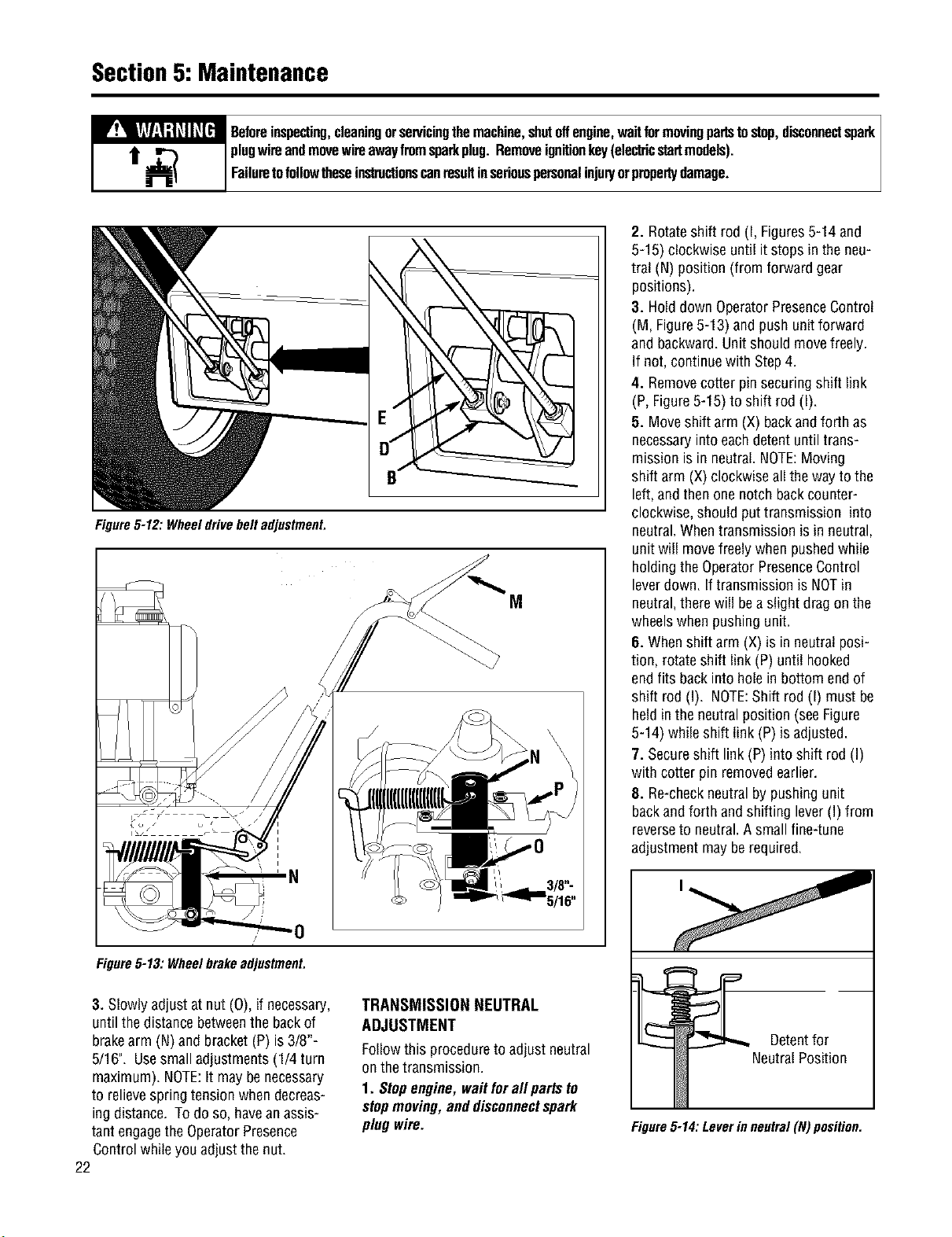
2. Disengage(release)theOperator
PresenceControl(M,Figure5-13).
21
Section5: Maintenance
_ eforeinspecting,cleaningorservicingthemachine,shutoffengine,waitformovingpartstostop,disconnectspark
plugwireandmovewireawayfromsparkplug.Removeignitionkey(electricstartmodels).
Failuretofollowtheseinsb'uctionscanresultinseriouspersonalinjuryorpropertydamage.
Figure5-12: Wheeldrivebeltadjustment.
Figure5-13: Wheelbrakeadjustment.
3. Slowly adjustat nut (0), if necessary,
untilthedistancebetweenthe backof
brakearm (N)and bracket(P) is3/8"-
5/16". Usesmall adjustments(1/4 turn
maximum).NOTE:It maybe necessary
to relievespringtensionwhendecreas-
ingdistance. To do so, havean assis-
tant engagethe OperatorPresence
Controlwhileyouadjust thenut.
22
TRANSMISSION NEUTRAL
ADJUSTMENT
Followthis procedureto adjustneutral
onthetransmission.
1. Stopengine,waitforallparts to
stepmoving,anddisconnectspark
plugwire.
2. Rotateshift rod (I, Figures5-14and
5-15) clockwiseuntil it stopsin the neu-
tral (N) position (from forward gear
positions).
3. HolddownOperatorPresenceControl
(M, Figure5-13) andpush unitforward
and backward.Unit shouldmovefreely.
If not, continuewith Step4.
4. Removecotter pinsecuringshift link
(P,Figure5-15)to shift rod (I).
5. Moveshiftarm (X) backandforth as
necessaryintoeachdetent untiltrans-
missionis in neutral.NOTE:Moving
shift arm (X) clockwiseallthe wayto the
left,and thenone notchbackcounter-
clockwise,shouldputtransmission into
neutral.Whentransmissionis in neutral,
unitwill movefreelywhen pushedwhile
holdingtheOperatorPresenceControl
leverdown. If transmissionis NOTin
neutral,therewill bea slight drag on the
wheelswhenpushingunit.
6. Whenshift arm (X) is in neutralposi-
tion, rotateshift link (P)until hooked
endfits backinto holein bottom endof
shift rod (I). NOTE:Shift rod (I) mustbe
heldin theneutralposition (seeFigure
5-14) while shift link (P) isadjusted.
7. Secureshift link(P) into shift rod (I)
with cotterpin removedearlier.
8. Re-checkneutralbypushingunit
backandforth andshifting lever(I) from
reverseto neutral.A smallfine-tune
adjustmentmay berequired.
Detentfor
NeutralPosition
Figure5-14:Leverinneutral(N)posifion,
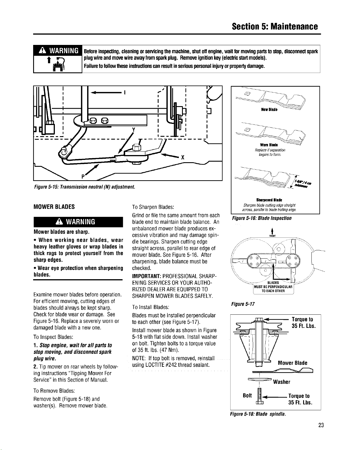
Section5: Maintenance
_ eforeinspecting,cleaningorservicingthemachine,shutoffengine,waitformovingpartstostop,disconnectspank
plugwireandmovewireawayfromspankplug.Removeignitionkey(electricstartmodels).
Failuretofollowtheseinstructionscanresultinseriouspersonalinjur/orpropertydamage.
i I
I
Y I
Figure5-15: Transmissionneutral(N) adjustment,
MOWERBLADES
Mowerbladesaresharp.
• When working near blades, wear
heavyleatherglovesor wrapbladesin
thick ragsto protectyourselffrom the
sharpedges.
• Wear eye protectionwhensharpening
blades.
Examinemowerbladesbeforeoperation.
Forefficientmowing,cutting edgesof
bladesshouldalwaysbe keptsharp.
Checkfor bladewearor damage. See
Figure5-16. Replacea severelyworn or
damagedbladewith a newone.
ToInspect Blades:
1. Stopengine,waitforall partsto
stopmoving,anddisconnectspark
plugwire.
2. Tip moweron rearwheelsbyfollow-
ing instructions"Tipping MowerFor
Service"inthis Sectionof Manual.
ToRemoveBlades:
Removebolt (Figure5-18) and
washer(s). Removemowerblade.
ToSharpenBlades:
Grindor file thesameamountfrom each
bladeend to maintainbladebalance.An
unbalancedmowerbladeproducesex-
cessivevibration andmaydamagespin-
dle bearings.Sharpencuttingedge
straightacross,parallelto rearedgeof
mower blade.SeeFigure5-16. After
sharpening,bladebalancemustbe
checked.
IMPORTANT:PROFESSIONALSHARP-
ENINGSERVICESORYOURAUTHO-
RIZEDDEALERAREEQUIPPEDTO
SHARPENMOWERBLADESSAFELY.
ToInstallBlades:
Bladesmustbe installedperpendicular
to eachother(seeFigure5-17).
Install mowerbladeasshown in Figure
5-18 with flat sidedown. Installwasher
on bolt. Tightenboltsto atorquevalue
of 35 ft. Ibs.(47 Nm).
NOTE:If top bolt is removed,reinstall
usingLOCTITE#242 threadsealant.
NewBlade
WornBlade
Replaceff separation
begins to form.
SharpenedBlade
SharOn blade cuttingedgesb_ight
across,parallel tobladetrailing edge
Figure5-16:BladeInspection
t
s _
Figure5-17
Torqueto
35 Ft.Lbs.
erBlade
I
_:=Washer
Bolt I_-.<--- Torqueto
35 Ft. Lbs.
Figure5-18: Blade spindle.
23
Section5: Maintenance
_ eforeinspecting,cleaningorservicingthemachine,shutoffengine,waitformovingpartstostop,disconnectspark
plugwireandmovewireawayfromsparkplug.Removeignitionkey(elecbicstartmodels).
Failuretofollowtheseinslructionscanresultinseriouspersonalinjuryorpropertydamage.
CLEANINGUNDERSIDEOF
MOWERDECK
Mowerbladesaresharp.
Whenworkingnearblades,wearheavy
leather glovesor wrap bladesin thick
ragsto protectyourselffrom the sharp
edges.
Frequentlycheck,and cleanif necessary,
the undersideof themowerdeck. Grass
build-upin this areacanaffectthe cut-
ting performance.Beforeinspectingor
cleaning,makesurethat theengineis
shut off andthespark plugwire is
disconnectedfrom thespark plug.
Inspection/Cleaningof Mower Deck:
1. Stepengine,waitforall partsto
stopmoving,anddisconnectspark
plugwire.
2. Tip moweron rearwheelsbyfollow-
ing instructions'q-ippingMowerFor
Service"inthis Section.
3. Usea plasticor metal scraperto
removegrassbuild-upfrom deckor
blades.
LUBRICATION
Oilandgreasethemoweraccordingto
the recommendationslisted inthe
LubricationCharton the nextpage.
• Stopengine, waitforallparts tostop
moving,anddisconnectsparkplug
wirebeforeperforminganylubrication
procedures.
•Thetransmissionhasbeenfactory
sealedand requiresno lubrication. If a
leakshoulddevelop,contactthefactory
or your localauthorizeddealerfor
serviceinformation.
OFF-SEASONSTORAGE
• Stopengine, waitforallparts tostop
moving,anddisconnectsparkplug
wirebeforeperforminganystorage
procedures.Reviewthestoragesafety
rulesin theSafetySectionofthis
Manual.
• If enginewill be unusedfor 30 daysor
more,prepareitfor storagebyfollowing
the recommendedproceduresfound in
the EngineOwner'sManual.
• Inspectall partsfor damage,breakage,
andwear. Tightenor replacefasteners.
Contactthefactoryor your local
authorizeddealerforfactory-approved
replacementparts.
•Cleanthe exteriorofthe mowerthor-
oughlyandtouch upall chippedor
scratchedsurfacesto preventrust from
forming.
Never store machine with fuel in the
fueltankinsidea buildingwherefumes
may reachan openflame or spark,or
where ignition sources are present
suchas hot water and space heaters,
furnaces,clothesdryers,stoves,elec-
tric motors,etc.
24
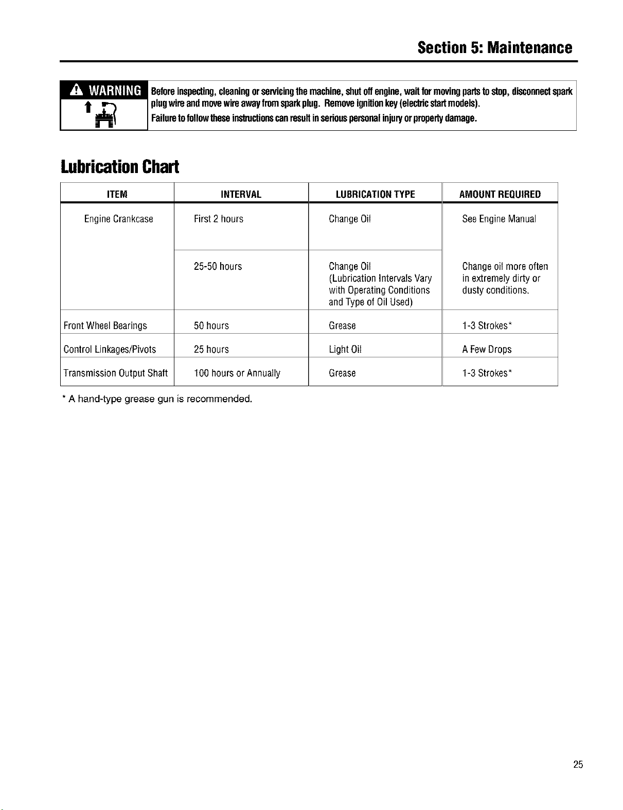
Section5: Maintenance
_ eforeinspecting,cleaningorservicingthemachine,shutoffengine,waitformovingpartstostop,disconnectspark
plugwireandmovewireawayfromsparkplug.Removeignitionkey(electricstartmodels).
Failuretofollowtheseinstructionscanresultinseriouspersonalinjup/orpropertydamage.
LubricationChart
LUBRICATIONTYPE AMOUNTREQUIRED
ChangeOil SeeEngineManual
ITEM INTERVAL
EngineCrankcase First2 hours
25-50 hours
FrontWheelBearings 50 hours
Control Linkages/Pivots 25 hours
TransmissionOutputShaft 100hoursor Annually
* A hand-type grease gun is recommended.
ChangeOil
(LubricationIntervalsVary
with OperatingConditions
andTypeof Oil Used)
Changeoil moreoften
inextremelydirty or
dustyconditions,
Grease 1-3 Strokes*
LightOil A FewDrops
Grease 1-3 Strokes*
25
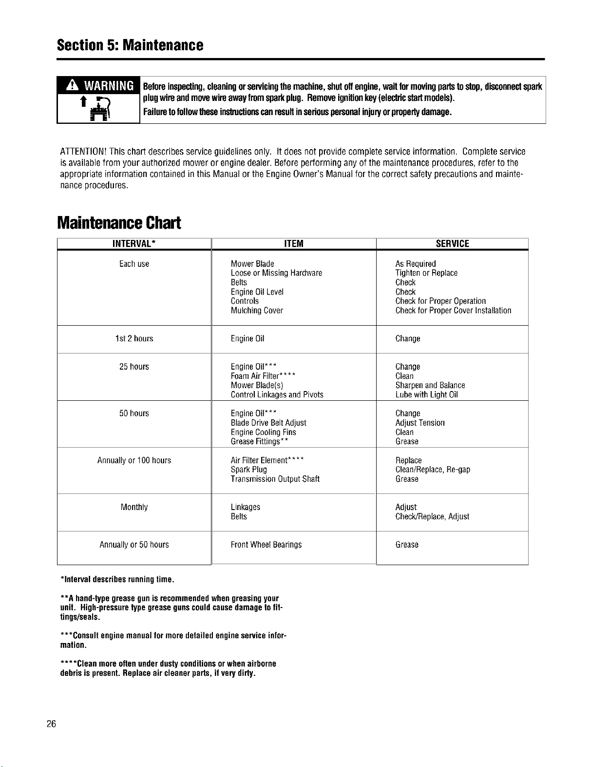
Section5: Maintenance
_ eforeinspecting,cleaningorservicingthemachine,shutoffengine,waitformovingpartstostop,disconnectspark
plugwire andmovewireawayfromsparkplug. Removeignitionkey(electricstartmodels).
Failuretofollowtheseinstructionscanresult inserious personalinjup/orpropertydamage.
ATTENTION!This chart describesserviceguidelinesonly. It doesnot providecompleteserviceinformation. Completeservice
isavailablefrom yourauthorizedmower or enginedealer.Beforeperforminganyof the maintenanceprocedures,referto the
appropriateinformationcontainedin this Manualor the EngineOwner'sManualfor thecorrectsafetyprecautionsandmainte-
nanceprocedures.
MaintenanceChart
INTERVAL*
Eachuse
1st 2hours
25 hours
50 hours
Annuallyor 100 hours
Monthly
Annuallyor 50 hours
ITEM
MowerBlade
Looseor Missing Hardware
Belts
EngineOilLevel
Controls
MulchingCover
EngineOil
EngineOil***
FoamAir Filter....
MowerBlade(s)
Control LinkagesandPivots
EngineOil***
BladeDriveBeltAdjust
EngineCoolingFins
GreaseFittings**
Air FilterElement....
SparkPlug
TransmissionOutputShaft
Linkages
Belts
FrontWhealBearings
SERVICE
AsRequired
Tightenor Replace
Check
Check
Checkfor ProperOperation
Checkfor ProperCoverInstallation
Change
Change
Clean
SharpenandBalance
Lubewith LightOil
Change
Adjust Tension
Clean
Grease
Replace
Clean/Replace,Re-gap
Grease
Adjust
Check/Replace,Adjust
Grease
*Intervaldescribesrunningtime.
**A hand-typegreasegunisrecommendedwhengreasingyour
unit. High-pressuretypegreasegunscouldcausedamagetofit-
tings/seals.
***Consult enginemanualformoredetailedengineserviceinfor-
mation.
****Clean moreoftenunderdustyconditionsorwhenairborne
debrisispresent.Replaceair cleanerparts,ifvery dirty.
26
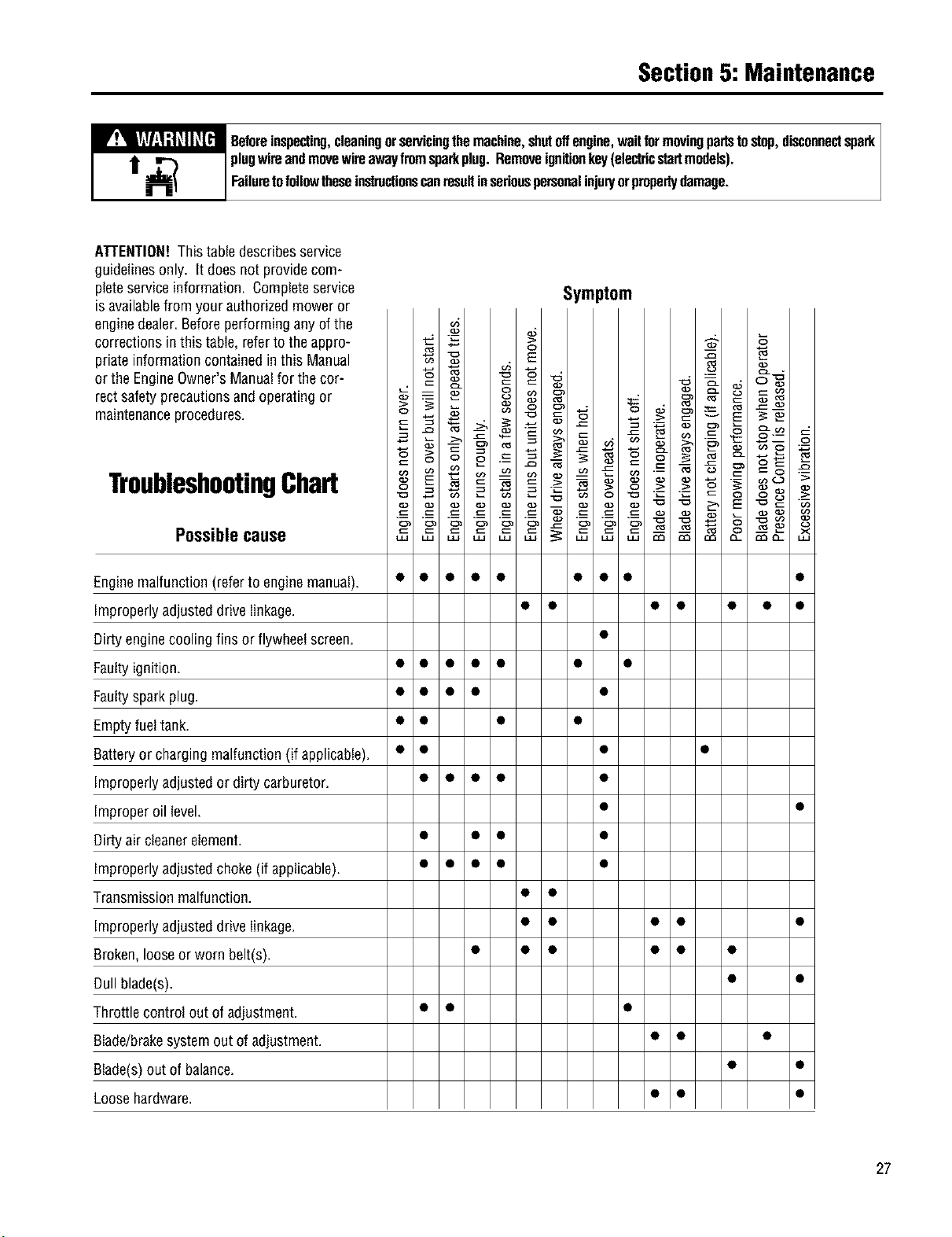
Section5: Maintenance
_ eforeinspecting,cleaningorservicingthemachine,shutoffengine,waitformovingpartstostop,disconnectspark
plugwireandmovewireawayfromsparkplug.Removeignitionkey(electricstartmodels).
Failuretofollowtheseinstructionscanresultinseriouspersonalinjup/orpropertydamage.
ATTENTION!This tabledescribesservice
guidelinesonly. It doesnotprovidecom-
pleteserviceinformation. Completeservice
is availablefrom your authorizedmoweror
enginedealer.Beforeperforminganyof the
correctionsin this table, referto the appro-
priateinformationcontainedinthis Manual
or the EngineOwner'sManualfor thecor-
rect safetyprecautionsandoperatingor
maintenanceprocedures.
TroubleshootingChart
Possiblecause
Symptom
Enginemalfunction(referto enginemanual). • • • • • • • • •
improperlyadjusteddrivelinkage. • • • • • • •
Dirtyenginecoolingfins or flywheelscreen. •
Faultyignition. • • • • • • •
Faultysparkplug. • • • • •
Emptyfueltank. • • • •
Batteryor chargingmalfunction(if applicable). • • • •
improperlyadjustedor dirtycarburetor. • • • • •
improperoil level. • •
Dirtyair cleanerelement. • • • •
improperlyadjustedchoke (if applicable). • • • • •
]-ransmissionmalfunction. • •
improperlyadjusteddrivelinkage. • • • • •
Broken,Iooseor worn belt(s). • • • • • •
Dullblade(s). • •
]-hrottlecontrol out ofadjustment. • • •
Blade/brakesystemout of adjustment. • • •
Blade(s)out of balance. • •
Loosehardware. • • •
27
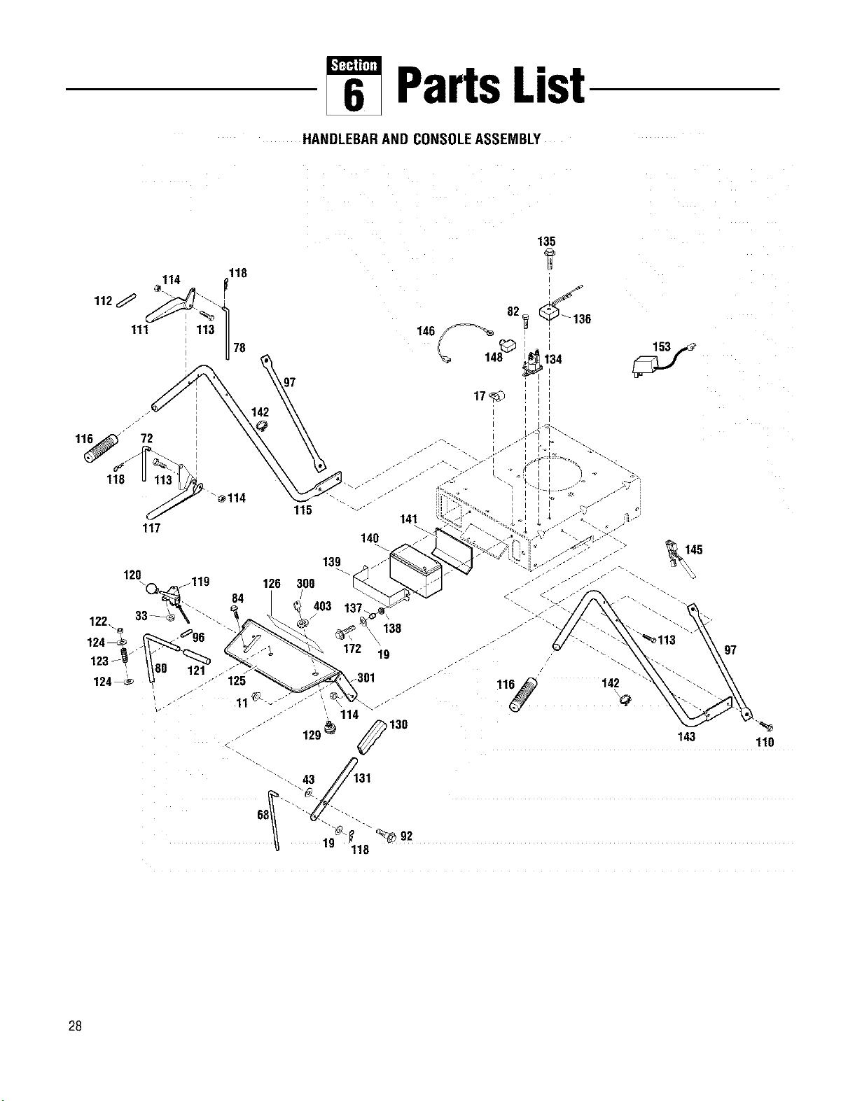
PartsList
HANDLEBARAND CONSOLEASSEMBLY
118
114
111 113 II
U
78
146
135
1r
_=_ 82_ _136
148_ _134
170
115
126 300
/
403
141
140
97
130
143 110
28
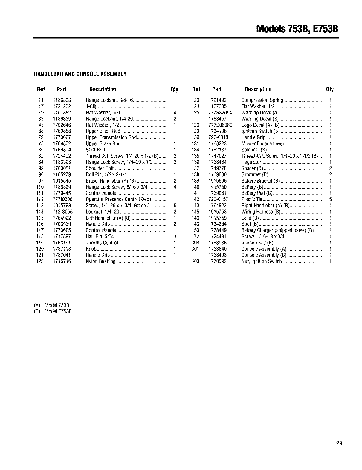
Models753B,E753B
HANDLEBARAND CONSOLEASSEMBLY
Ref. Part Description Qty. Ref. Part Description Qty.
11 1186393
17 1721252
19 1107382
33 1186389
43 1702646
68 1769888
72 1773607
78 1769872
80 1769874
82 1724492
84 1186308
92 1703051
96 1185279
97 1915545
110 1186329
111 1770445
112 777100001
113 1915793
114 712-3055
115 1764922
116 1703539
117 1773605
118 1717897
119 1768191
120 1737118
121 1737041
122 1715716
FlangeLoeknut,3/8-16........................... 1
J-Clip...................................................... 1
FlatWasher,5/16 ................................... 4
RangeLocknut,1/4-20........................... 2
FlatWasher,1/2..................................... 1
UpperBladeRed.................................... 1
UpperTransmissionRod........................ 1
UpperBrakeRod.................................... 1
Shift Rod................................................ 1
ThreadCot.Screw,1/4-20 x 1/2 (B)....... 2
FlangeLockScrew, 1/4-20 x !/2 ........... 2
ShoulderBolt ......................................... 1
RollPin,1/4 x 2-1/4............................... 1
Brace,Handlebar(A)(B)........................ 2
FlangeLockScrew,5/16 x 3/4............... 4
Control Handle....................................... 1
OperatorPresenceControl Decal........... 1
Screw,1/4-20 x 1-3/4,Grade8............. 6
Locknut,1/4-20 ..................................... 2
LeftHandlebar(A) (B)............................ 1
HandleGrip............................................ 2
Control Handle....................................... 1
HairPin,5/64......................................... 3
Throttle Control...................................... 1
Knob....................................................... 1
HandleGrip............................................ 1
NylonBushing........................................ 1
123 1721492
124 1107385
125 777S32064
1768457
126 777D06080
129 1734196
130 720-0313
131 1768223
134 1752137
135 1747027
136 1768464
137 1749778
138 1769080
139 1915696
140 1915750
141 1769081
142 725-0157
143 1764923
145 1915758
146 1915759
148 1734364
163 1768449
172 1724491
300 1753986
301 1768640
1768493
403 1770592
(A) Model753B
(B) Model E753B
29
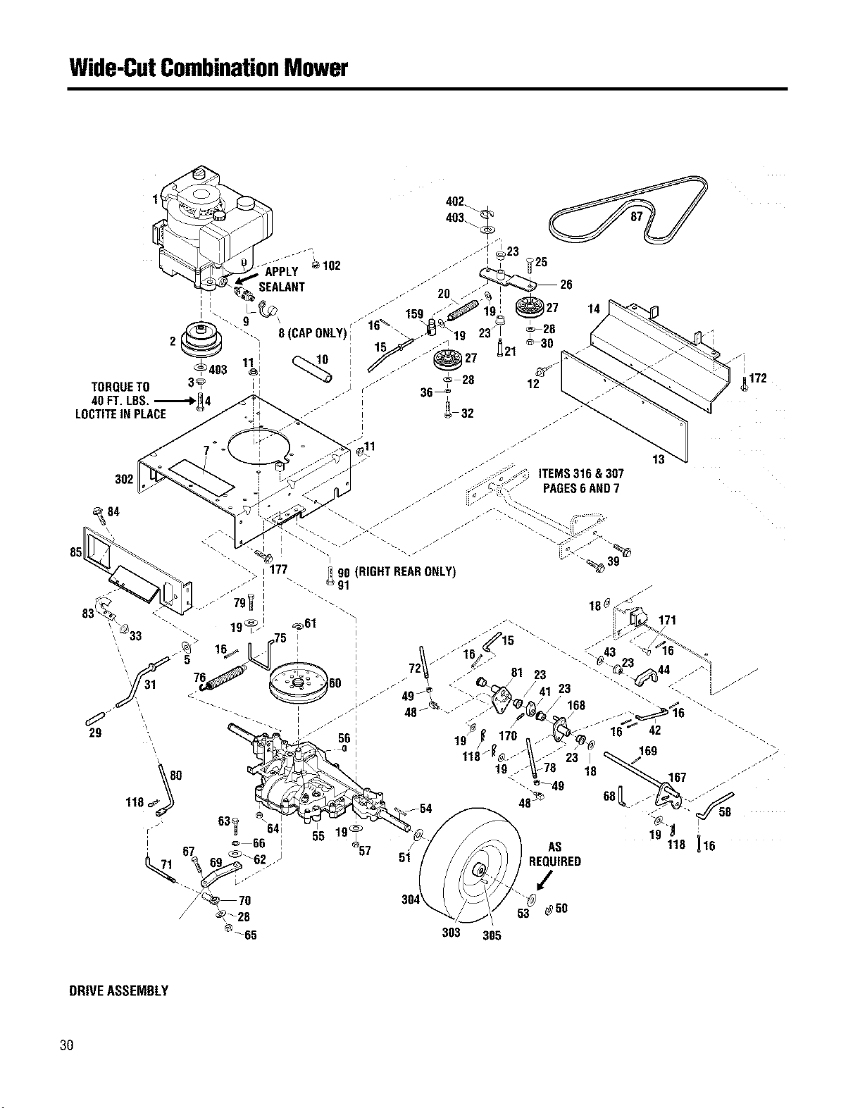
Wide-CutCombinationMower
TORQUETO
40 FT. LRS..._1,'_4
LOCTITEIN PLACE
c_o
172
302
_84
85
303
AS
REQUIRED
/
53 @50
305
DRIVEASSEMBLY
30
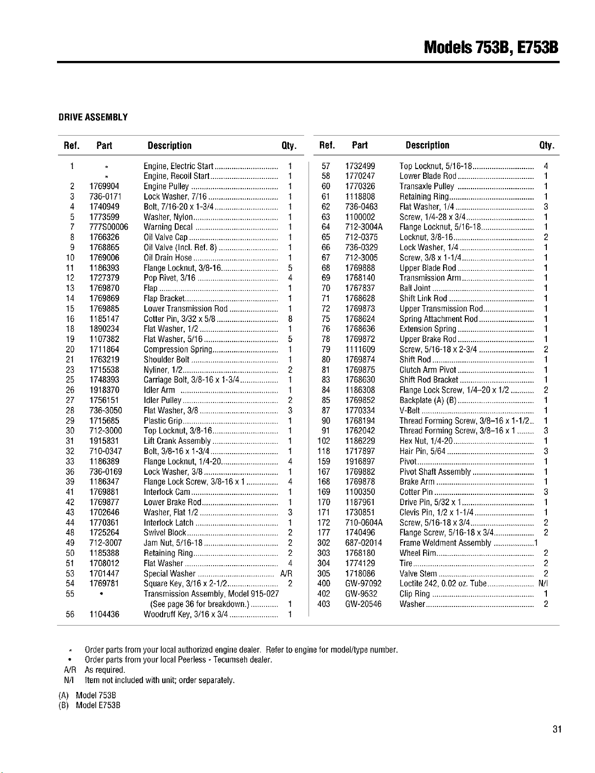
Models753B,E753B
DRIVE ASSEMBLY
Ref. Pert Description Qty. Ref. Pert Description Qty.
1
2 1769904
3 736-0171
4 1740949
5 1773599
7 777S00006
8 1766326
9 1768865
10 1769006
11 1186393
12 1727379
13 1769870
14 1769869
15 1769885
16 1185147
18 1890234
19 1107382
20 1711864
21 1763219
23 1715538
25 1748393
26 1918370
27 1756151
28 736-3050
29 1715685
30 712-3000
31 1915831
32 710-0347
33 1186389
36 736-0169
39 1186347
41 1769881
42 1769877
43 1702646
44 1770361
48 1725264
49 712-3007
50 1185388
51 1708012
53 1701447
54 1769781
55
56 1104436
Engine,ElectricStart.............................. 1
Engine,RecoilStart................................ 1
EnginePulley......................................... 1
LockWasher,7/16................................. 1
Bolt, 7/16-20x 1-3/4.............................. 1
Washer,Nylon........................................ 1
WarningDecal ....................................... 1
OilValveCap.......................................... 1
OilValve(Incl. Ref.8) ............................ 1
Oil DrainHose........................................ 1
FlangeLocknut,3/8-16........................... 5
Pop Rivet,3/16 ...................................... 4
Flap........................................................ I
FlapBracket............................................ I
LowerTransmissionRod....................... I
CotterPin,3/32x 5/8............................. 8
FlatWasher,1/2..................................... 1
FlatWasher,5/16................................... 5
CompressionSpring............................... 1
ShoulderBolt......................................... 1
Nyliner,1/2............................................. 2
CarriageBolt,3/8-16 x 1-3/4.................. 1
IdlerArm .............................................. 1
Idler Pulley............................................. 2
FlatWasher,3/8 ..................................... 3
PlasticGrip............................................. 1
TopLocknut,3/8-16............................... 1
Lift CrankAssembly............................... 1
Bolt, 3/8-16x 1-3/4................................ 1
FlangeLocknut,1/4-20........................... 4
LockWasher,3/8................................... 1
FlangeLockScrew,3/8-16 x 1............... 4
Interlock Cam......................................... 1
LowerBrakeRod.................................... 1
Washer,Flat 1/2..................................... 3
Interlock Latch....................................... 1
Swivel Block........................................... 2
Jam Nut,5/16-18................................... 2
RetainingRing........................................ 2
FlatWasher............................................ 4
SpecialWasher.................................... A/R
SquareKey,3/16x 2-1/2........................ 2
TransmissionAssembly,Model915-027
(Seepage36 for breakdown.)............. 1
Woodruff Key,3/16x 3/4....................... 1
57 1732499
58 1770247
60 1770326
61 1118808
62 736-0463
63 1100002
64 712-3004A
65 712-0375
66 736-0329
67 712-3005
68 1769888
69 1768140
70 1767837
71 1768628
72 1769873
75 1768624
76 1768636
78 1769872
79 1111609
80 1769874
81 1769875
83 1768630
84 1186308
85 1769852
87 1770334
90 1768194
91 1762042
102 1186229
118 1717897
159 1916897
167 1769882
168 1769878
169 1100350
170 1187961
171 1730851
172 710-0604A
177 1740496
302 687-02014
303 1768180
304 1774129
305 1718086
400 GW-97092
402 GW-9532
403 GW-20546
TopLocknut, 5116-18............................. 4
Lower BladeRod.................................... I
TransaxlePulley .................................... I
RetainingRing........................................ I
FlatWasher,114..................................... 3
Screw,114-28x 3/4................................ I
FlangeLocknut, 5116-18......................... I
Locknut, 3/8-16...................................... 2
LockWasher,114................................... I
Screw,318x I-I/4 .................................. I
UpperBladeRod.................................... I
TransmissionArm.................................. I
BallJoint ................................................ I
Shift Link Rod........................................ I
UpperTransmissionRod........................ I
Spring AttachmentRod.......................... 1
ExtensionSpring.................................... I
UpperBrakeRod.................................... 1
Screw,5116-18x 2-3/4 .......................... 2
Shift Rod................................................ 1
ClutchArm Pivot.................................... 1
Shift Rod Bracket................................... 1
FlangeLock Screw,1/4-20 x 1/2........... 2
Backplate(A) (B).................................... 1
V-Belt..................................................... 1
ThreadFormingScrew,3/8-16 x 1-1/2.. 1
ThreadFormingScrew,3/8-16 x 1 ........ 3
HexNut, 1/4-20...................................... 1
Hair Pin,5/64......................................... 3
Pivot....................................................... 1
PivotShaftAssembly............................. 1
BrakeArm .............................................. 1
CotterPin............................................... 3
DrivePin,5/32 x I .................................. I
ClevisPin,112x I-I/4 ............................ I
Screw,5116-18x 314.............................. 2
FlangeScrew,5/16-18 x 314................... 2
FrameWeldmentAssembly...................1
WheelRim.............................................. 2
Tire......................................................... 2
ValveStem............................................. 2
Loctite242,0.02 oz.Tube...................... Nil
ClipRing ................................................ I
Washer................................................... 2
Orderpartsfrom your localauthorizedenginedealer. Referto enginefor model/typenumber.
Orderpartsfrom your localPeerless-Tecumsehdealer.
A/R As required.
N/I Item not includedwith unit; order separately.
(A) Model753B
(B) ModelE753B
31
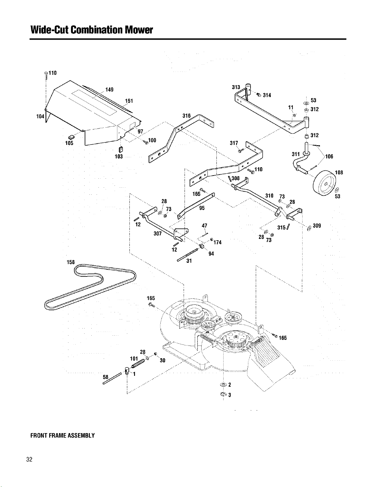
Wide-CutCombinationMower
_110
I
I
I
0
105
158
149
103
151
11
_53
_312
31|
I
I
165
28
j"
Lj-j
FRONTFRAMEASSEMBLY
32
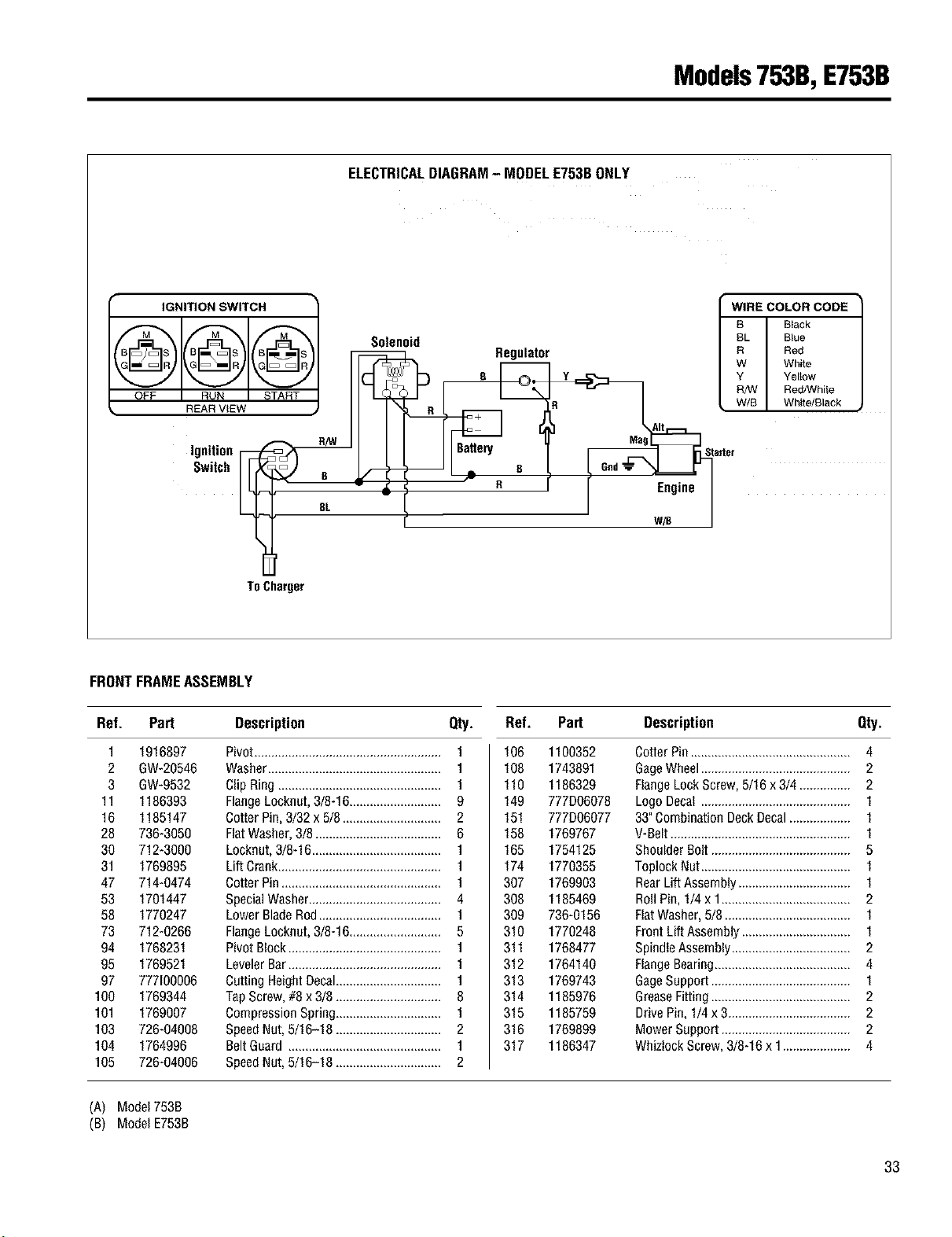
Models753B,E753B
ELECTRICALDIAGRAM- MODELE753BONLY
IGNITIONSWITCH [ WIRECOLORCODE •
_=_ l B Black
Solenoid BL Blue
B/_ I/'_ _ Regulator R Red
G • ] W White
_ Y Y Yellow
RhN Red/White
OFF RUN START J W/B White{Black ,
Ignition _ Gad T Starter
Sw,tohiir j a I . o o I
EL _ n I
W/B
I
ToCharger
FRONTFRAMEASSEMBLY
Ref. Part Description Qty. Ref. Part Description Qty.
1 1916897
2 GW-20546
3 GW-9532
11 1186393
16 1185147
28 736-3959
30 712-3909
31 1769895
47 714-9474
53 1791447
58 1770247
73 712-0266
94 1768231
95 1769521
97 777100006
100 1769344
101 1769907
103 726-94098
104 1764996
105 726-04096
Pivot....................................................... I
Washer................................................... I
Clip Ring................................................ I
FlangeLoeknut,318-16........................... 9
CotterPin,3132x 5/8 ............................. 2
FlatWasher,318..................................... 6
Locknut,318-16...................................... I
LiftCrank................................................ I
CotterPin............................................... I
SpecialWasher....................................... 4
LowerBladeRod.................................... I
FlangeLoeknut,3/8-16........................... 5
PivotBlock............................................. I
LevelerBar............................................. 1
CuttingHeightDecal............................... 1
TapScrew,#8 x 3/8 ............................... 8
CompressionSpring............................... 1
SpeedNut,5/16-18 ............................... 2
BeltGuard ............................................. 1
SpeedNut,5/16-18 ............................... 2
106 1100352
108 1743891
110 1186329
149 777D06078
151 777D06077
158 1769767
165 1754125
174 1770355
397 1769903
398 1185469
399 736-9156
310 1770248
311 1768477
312 1764149
313 1769743
314 1185976
315 1185759
316 1769899
317 1186347
CotterPin............................................... 4
GageWheel............................................ 2
FlangeLockScrew,5/16 x 3/4 ............... 2
LogoDecal ............................................ 1
33"CombinationDeckDecal.................. 1
V-Belt..................................................... 1
Shoulder Bolt......................................... 5
Toplock Nut............................................ 1
RearLiftAssembly................................. I
RollPin, I/4 x I ...................................... 2
FlatWasher,5/8 ..................................... 1
FrontLiftAssembly................................ I
SpindleAssembly................................... 2
FlangeBearing........................................ 4
GageSupport......................................... 1
GreaseFitting......................................... 2
DrivePin,1/4 x 3.................................... 2
Mower Support ...................................... 2
WhizlockScrew,3/8-16x 1.................... 4
(A) Model753B
(B) Model E753B
33

Wide-CutCombinationMower
158
400 LOCTITE242, 0.02OZ.TUBE
MOWERDECKASSEMBLY
34
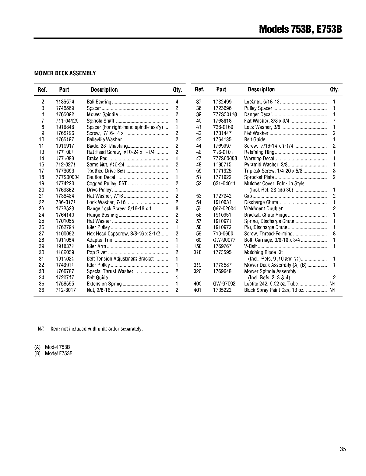
Models753B,E753B
MOWER DECKASSEMBLY
Ref. Pert Description Qty. Ref. Pert Description Qty.
2 1185574
3 1746869
4 1765092
7 711-04020
8 1918848
9 1765196
10 1765197
11 1910917
13 1771081
14 1771083
15 712-0271
17 1773600
18 777S00004
19 1774220
20 1769362
21 1736484
22 736-0171
23 1773523
24 1764140
25 1701055
26 1762794
27 1100062
28 1911054
29 1918371
30 1186059
31 1911021
32 1749911
33 1766787
34 1720717
35 1756595
36 712-3017
BallBearing............................................ 4
Spacer.................................................... 2
MowerSpindle....................................... 2
SpindleShaft ......................................... 1
Spacer(Forright-handspindle ass'y) .... 1
Screw, 7/1G14 x 1................................ 2
BellevilleWasher.................................... 2
Blade,33" Mulching................................ 2
FlatHeadScrew, #10-24 x 1-1/4 ........... 2
BrakePad............................................... 1
SeresNut,#10-24 ................................. 2
ToothedDrive Belt................................. 1
CautionDecal........................................ 1
CoggedPulley,56T................................ 2
DrivePulley............................................ 1
FlatWasher,7/16 ................................... 2
LockWasher,7/16................................. 2
FlangeLockScrew,5/16-18x 1............. 8
FlangeBushing....................................... 2
FlatWasher............................................ 2
IdlerPulley............................................. 1
HexHeadCapscrew,3/8-16 x 2-1/2....... 2
AdapterTrim .......................................... 1
IdlerArm ................................................ 1
PopRivet............................................... 2
BeltTensionAdjustment Bracket........... 1
IdlerPulley............................................. 1
SpecialThrust Washer........................... 2
BeltGuide............................................... 1
ExtensionSpring .................................... 1
Nut,3/8-16............................................. 2
37 1732499
38 1723996
39 777S30118
40 1768818
41 73Gg169
42 1701447
43 1764135
44 1769397
46 71G0101
47 777S00008
48 1185715
50 1771925
51 1771922
52 631-04011
53 1727342
54 1910931
55 687-02004
56 1910951
57 1910971
58 1910972
59 710-0650
60 GW-90077
158 1769767
318 1773595
319 1773587
320 1769048
400 GW-97092
401 1735222
Locknut,5/1G18.................................... 1
PulleySpacer......................................... 1
DangerDecal.......................................... 1
FiatWasher,3/8 x 3/4 ............................ 7
LockWasher,3/8 ................................... 1
FiatWasher............................................ 2
BeltGuide............................................... 1
Screw, 7/1G14 x 1-1/4 ......................... 2
RetainingRing........................................ 1
Warning Decal........................................ 1
PyramidWasher,3/8.............................. 1
Triplask Screw,1/4-20x 5/8 .................. 8
SprocketPlate........................................ 2
MulcherCover,Fold-UpStyle
(Incl. Ref.28and 30) ......................... 1
Cap......................................................... 2
DischargeChute..................................... 1
Weldment Doubler................................. 2
Bracket,ChuteHinge.............................. 1
Spring,DischargeChute......................... 1
Pin,DischargeChute.............................. 1
Screw,Thread-Forming.......................... 8
Bolt,Carriage,3/8-18x 3/4 .................... 1
V-Belt..................................................... 1
Mulching BladeKit
(Incl. Refs.9,10 and 11).................... 1
Mower DeckAssembly(A) (B)............... 1
Mower SpindleAssembly
(Incl. Refs.2, 3 & 4)............................ 2
Loctite242,0.02oz.Tube...................... N/I
BlackSprayPaintCan,13oz................. Nil
N/I Itemnot includedwith unit; orderseparately.
(A) Model753B
(B) Model E753B
35
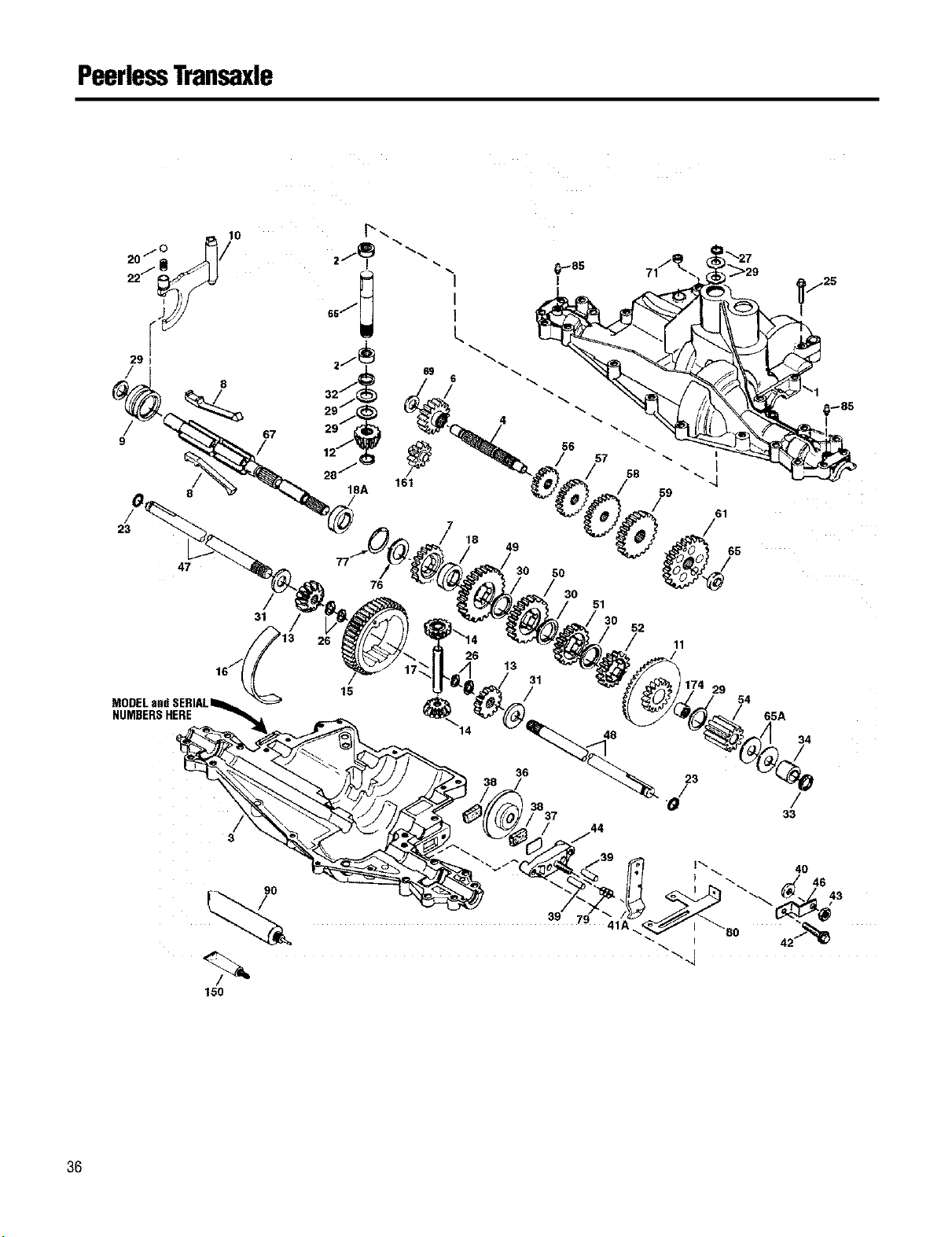
PeerlessTransaxle
22J
29
/
8
/ 67
9
23
47
31
NUMBERSHERE
/
3
150
76
15
56
57
58
18
49
50
/ 30
51
52
26
13
31
48
36
38
37
11
29
54
65A
34
23
33
36
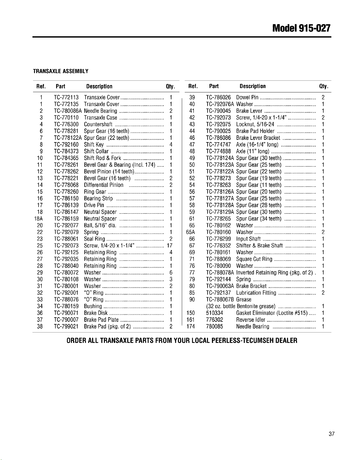
Model915-027
TRANSAXLEASSEMBLY
Ref. Part Description Qty. Ref. Part Description Qty.
1
1
2
3
4
6
7
8
9
10
11
12
13
14
15
16
17
18
18A
2O
22
23
25
26
27
28
29
30
31
32
33
34
36
37
38
TC-772113 TransaxleCover.............................. 1
TC-772135 TransaxleCover.............................. 1
TC-780086ANeedleBearing..................... 2
TC-770110 TransaxleCase............................... 1
TC-776300 Countershaft................................... 1
TC-778281 Spur Gear(16teeth) ................ 1
TC-778122ASpur Gear(22 teeth)....................... 1
TC-792160 Shift Key ......................................... 4
TC-784373
TC-784365
TC-778261
TC-778262
TC-778221
TC-778068
TC-778260
TC-786150
TC-786139
TC-786147
TC-786159
TC-792077
TC-792079
TC-788061
TC-792073
TC-792125
TC-792035
TC-788040
TC-780072
TC-780108
TC-780001
TC-792001
TC-788076
TC-780159
TC-790071
TC-790007
TC-799021
Shift Collar ......................... 1
Shift Rod& Fork ............................. 1
BevelGear& Bearing(Incl. 174)..... 1
BevelPinion(14 teeth).................... 1
BevelGear(16 teeth) ..................... 2
DifferentialPinion ......................... 2
RingGear........................................ 1
BearingStrip .................................. 1
DrivePin ......................................... 1
NeutralSpacer ............................... 1
NeutralSpacer ............................... 1
Ball,5/16" dia. ................................ 1
Spring ............................................. 1
SealRing......................................... 2
Screw,1/4-20x 1-1/4" .................... 17
RetainingRing ................................ 4
RetainingRing ................................ 1
RetainingRing ................................ 1
Washer............................................ 6
Washer............................................ 3
Washer............................................ 2
"0" Ring .......................................... 1
"0" Ring .......................................... 1
Bushing.......................................... 1
BrakeDisk ....................................... 1
BrakePadRate .............................. 1
BrakePad(pkg.of 2) ...................... 2
39 TC-786026 DowelPin........................................ 2
40 TC-792076AWasher........................................... 1
41 TC-790045 BrakeLever..................................... 1
42 TC-792073 Screw,1/4-20x 1-1/4". ................... 2
43 TC-792075 Locknut,5/16-24 ............................ 1
44 TC-790025 BrakePadHolder ............................ 1
46 TC-786086 BrakeLeverBracket........................ 1
47 TC-774747 Axle(16-1/4"long) ......................... 1
48 TC-774888 Axle(11" long) ................................ 1
49 TC-778124ASpur Gear(30 teeth)....................... 1
50 TC-778123ASpur Gear(25 teeth) ...................... 1
51 TC-778122ASpur Gear(22 teeth) ....................... 1
52 TC-778273 Spur Gear(19 teeth) ....................... 1
54 TC-778263 Spur Gear(11 teeth) ....................... 1
56 TC-778126ASpur Gear(20 teeth) ....................... 1
57 TC-778127ASpur Gear(25 teeth) ...................... 1
58 TC-778128ASpur Gear(28 teeth) ....................... 1
59 TC-778129ASpur Gear(30 teeth) ....................... 1
61 TC-778265 Spur Gear(34 teeth) ....................... 1
65 TC-780162 Washer........................................... 1
65A TC-780160 Washer........................................... 2
66 TC-776299 InputShaft ...................................... 1
67 TC-776352 Shifter & BrakeShaft ...................... 1
69 TC-780161 Washer........................................... 1
71 TC-788069 SquareCutRing .............................. 1
76 TC-780090 Washer........................................... 1
77 TC-788078AInvertedRetainingRing(pkg.of 2). 1
79 TC-792144 Spring ............................................. 1
80 TC-790063ABrakeBracket.................................. 1
85 TC-792137 LubricationFitting ........................... 2
90 TC-788067BGrease
(32 oz. bottle Bentonitegrease) ........................... 1
150 510334 GasketEliminator(Loctite#515) .... 1
161 776302 ReverseIdler........................ 1
174 780085 NeedleBearing ............................... 1
ORDERALLTRANSAXLEPARTSFROM YOURLOCALPEERLESS-TECUMSEHDEALER
37
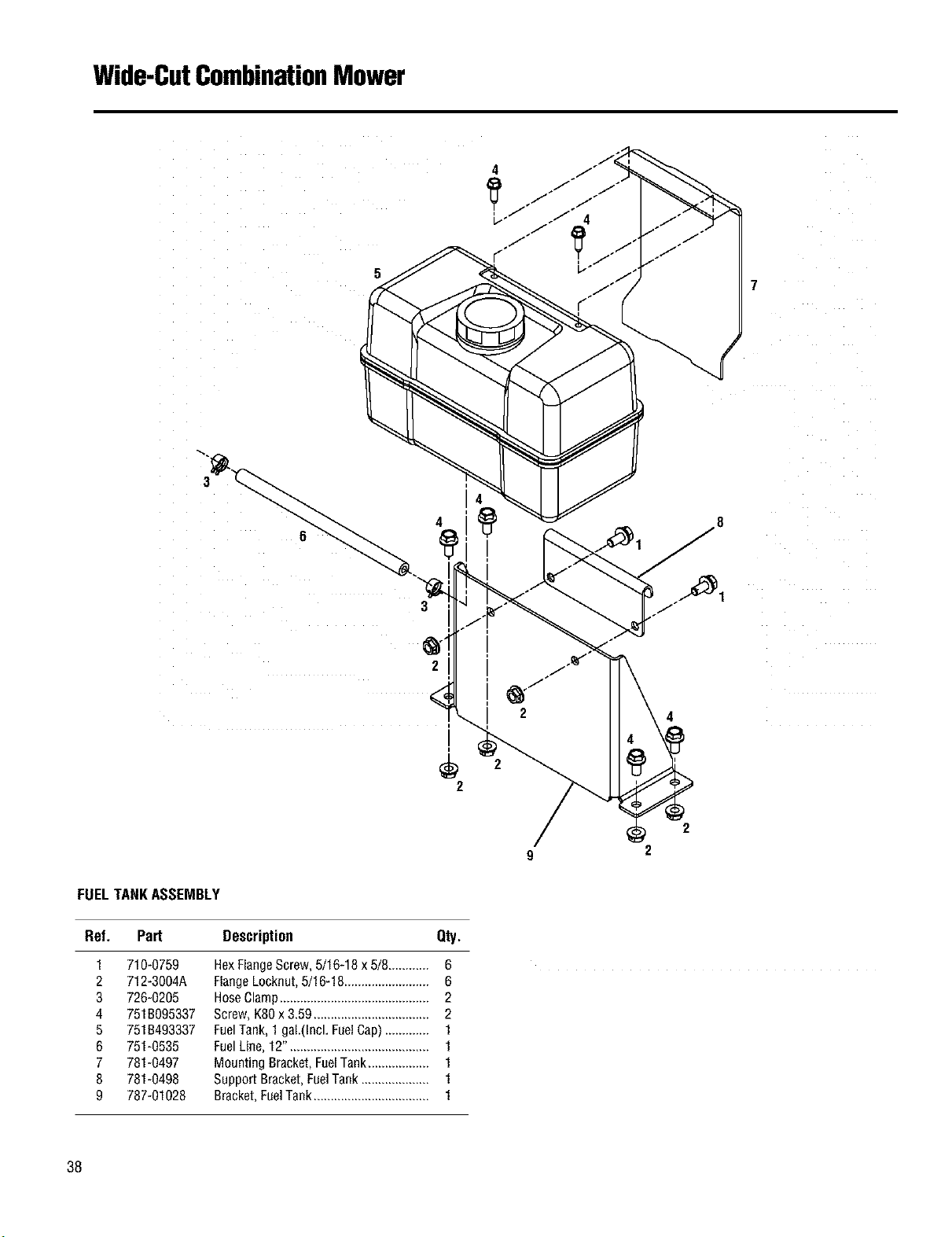
Wide-CutCombinationMower
5
7
3
2
2
4
2
2
9 2
FUELTANKASSEMBLY
Ref. Part Description Qty.
1
2
3
4
5
6
7
8
9
710-0759
712-3004A
726-0205
7518095337
7518493337
751-0535
781-0497
781-0498
787-01028
HexFlangeScrew,5/16-18x 5/8............ 6
FlangeLocknut,5/16-18......................... 6
HoseClamp............................................ 2
Screw,K80x 3.59.................................. 2
FuelTank, 1gaL(Incl,FuelCap)............. 1
FuelLine, 12"......................................... 1
Mounting Bracket,FuelTank.................. 1
SupportBracket,FuelTank .................... 1
Bracket,FuelTank.................................. 1
38

NOTES
39
MANUFACTURER'S LIMITED WARRANTY FOR:
0 TRIll BILT°
The limited warranty set forth below is given by Troy-Bilt LLC
with respect to new merchandise purchased and used in the
United States, its possessions and territories.
Troy-Bilt LLC warrants this product against defects for a period
of two (2) years commencing on the date of original purchase
and will, at its option, repair or replace, free of charge, any part
found to be defective in materials or workmanship. This limited
warranty shall only apply if this product has been operated and
maintained in accordance with the Operator's Manual furnished
with the product, and has not been subject to misuse, abuse,
commercial use, neglect, accident, improper maintenance, alter-
ation, vandalism, theft, fire, water, or damage because of other
peril or natural disaster. Damage resulting from the installation
or use of any accessory or attachment not approved by Troy-Bilt
LLC for use with the product(s) covered by this manual will void
your warranty as to any resulting damage.
Normal wear parts or components thereof are subject to sepa-
rate terms as follows: All normal wear parts or component fail-
ures will be covered on the product for a period of 90 days re-
gardless of cause. After 90 days, but within the two year period,
normal wear part failures will be covered ONLY IF caused by de-
fects in materials or workmanship of OTHER component parts.
Normal wear parts and components include, but are not limited
to: batteries, belts, blades, blade adapters, grass bags, rider
deck wheels, seats, snow thrower skid shoes, shave plates,
auger spiral rubber, tires.
NOW TO OBTAIN SERVICE= Warranty service is available,
WITH PROOF OF PURCHASE, through your local authorized
service dealer. To locate the dealer in your area, check your
Yellow Pages, or contact Troy-Bilt LLC at P.O. Box 361131,
Cleveland, Ohio 44136-0019, 1-866-840-6483, or log on to our
Web site at www.troybilt.com.
This limited warranty does not provide coverage in the following
oases:
a. The engine or component parts thereof. These items
carry a separate manufacturer's warranty. Refer to the
applicable manufacturer's warranty for terms and cond
tions.
b. Log splitter pumps, valves, and cylinders have a separate
one year warranty.
c. Routine maintenance items such as lubricants, filters,
blade sharpening, tune-ups, brake adjustments, clutch
adjustments, deck adjustments, and normal deterioration of
the exterior finish due to use or exposure.
d. Troy-Bilt LLC does not extend any warranty for products
sold or exported outside of the United States, its pos-
sessions and territories, except those sold through Troy-
Bilt LLC's authorized channels of export distribution.
e. Parts that are not genuine Troy-Bi]t parts are not covered by
this warranty.
f. Service completed by someone other than an authorized
service dealer is not covered by this warranty.
g. Transportation charges and service calls are not covered.
No implied warranty, including any implied warranty of mer-
chantability of fitness for a particular purpose, applies after
the applicable period of express written warranty above as
to the parts as identified. No other express warranty,
whether written or oral, except as mentioned above, given
by any person or entity, including a dealer or retailer, with
respect to any product, shall bind Troy-Bilt LLC. During the
period of the warranty, the exclusive remedy is repair or re-
placement of the product as set forth above.
The provisions as set forth in this warranty provide the sole
and exclusive remedy arising from the sale. Troy-Bilt LLC
shall not be liable for incidental or consequential loss or
damage including, without limitation, expenses incurred for
substitute or replacement lawn care services or for rental
expenses to temporarily replace a warranted product.
Some states do not allow the exclusion or limitation of incidental
or consequential damages, or limitations on how long an implied
warranty lasts, so the above exclusions or limitations may not
apply to you.
In no event shall recovery of any kind be greater than the
amount of the purchase price of the product sold. Alteration of
the safety features of the product shall void this warranty.
You assume the risk and liability for loss, damage, or injury to
you and your property and/or to others and their property arising
out of the misuse or inability to use the product.
This limited warranty shall not extend to anyone other than the
original purchaser or to the person for whom it was purchased
as a gift.
HOW STATE LAW RELATES TO THIS WARRANTY: This
limited warranty gives you specific legal rights, and you
may also have other rights which vary from state to state.
TROY-BILT LLC, P.O. BOX 361131, CLEVELAND, OHIO 44136-0019, 1-866-840-6483
4O