Loading ...
Loading ...
Loading ...
Section3: FeaturesandControls
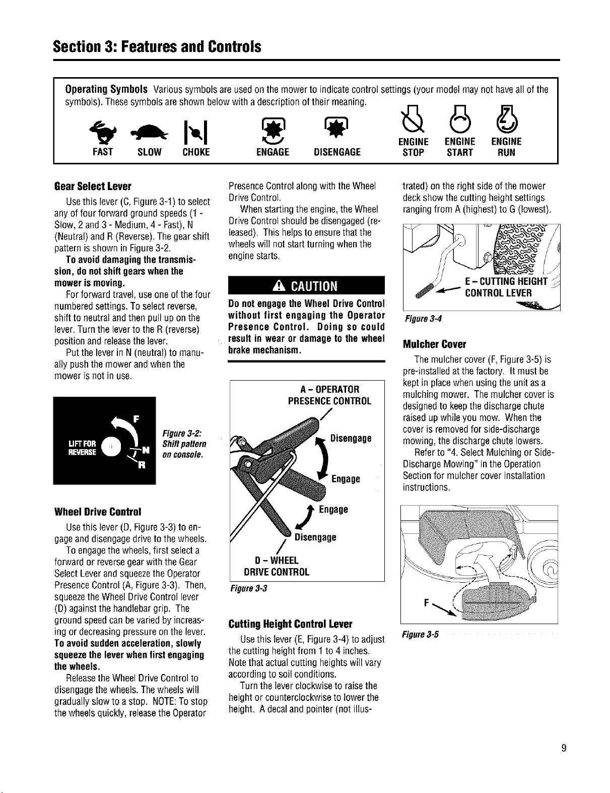
Operating Symbols Varioussymbolsare usedon the mowerto indicatecontrol settings(your modelmaynot haveall of the
symbols).Thesesymbolsareshown belowwith a descriptionof their meaning.
ENGINE ENGINE ENGINE
FAST SLOW CHOKE ENGAGE DISENGAGE STOP START RUN
GearSelect Lever
Usethis lever(C,Figure3-1) to select
anyof four forward groundspeeds(1 -
Slow,2 and 3 - Medium,4- Fast),N
(Neutral)andR(Reverse).Thegearshift
patternisshown in Figure3-2.
Toavoiddamagingthetransmis-
sion,donotshiftgearswhenthe
mowerismoving.
Forforward travel,useoneofthe four
numberedsettings.Toselectreverse,
shiftto neutralandthenpull upon the
lever.Turnthe leverto theR (reverse)
positionand releasethe lever.
Putthe leverin N(neutral)to manu-
allypushthemowerand whenthe
mower isnot in use.
Figure3-2:
Shiftpattern
onconsole.
Wheel Drive Control
Usethis lever(D, Figure3-3) to en-
gageand disengagedriveto thewheels.
Toengagethe wheels,first selecta
forwardor reversegearwith theGear
SelectLeverandsqueezetheOperator
PresenceControl(A, Figure3-3). Then,
squeezetheWheelDriveControllever
(D)againstthehandlebargrip. The
groundspeedcanbevariedbyincreas-
ing or decreasingpressureon thelever.
Toavoidsuddenacceleration, slowly
squeezetheleverwhenfirstengaging
thewheels.
Releasethe WheelDriveControlto
disengagethewheels.Thewheelswill
graduallyslowto a stop. NOTE:Tostop
thewheelsquickly, releasethe Operator
PresenceControlalongwith theWheel
DriveControl.
Whenstartingthe engine,theWheel
DriveControlshouldbedisengaged(re-
leased). This helpsto ensurethat the
wheelswill notstartturning whenthe
enginestarts.
Do notengagethe WheelDriveControl
without first engaging the Operator
Presence Control. Doing so could
resultin wearor damageto the wheel
brakemechanism.
A- OPERATOR
PRESENCECONTROL
Disengage
Engage
Engage
Disengage
D- WHEEL
DRIVECONTROL
Figure3-3
Cutting Height Control Lever
Usethis lever(E,Figure3-4) to adjust
the cutting heightfrom 1to 4 inches.
Notethat actualcutting heightswill vary
accordingto soil conditions.
Turn theleverclockwiseto raisethe
heightor counterclockwiseto lowerthe
height. Adecaland pointer(not illus-
trated) onthe right sideofthe mower
deckshow thecutting heightsettings
rangingfrom A (highest)to G (lowest).
Figure3-4
Mulcher Cover
The mulchercover (F,Figure3-5)is
pre-installedat thefactory. It must be
kept in placewhenusingtheunit asa
mulching mower. Themulchercoveris
designedto keepthe dischargechute
raisedup whileyou mow. Whenthe
cover is removedfor side-discharge
mowing,thedischargechutelowers.
Referto "4. SelectMulchingor Side-
DischargeMowing" inthe Operation
Sectionfor mulchercover installation
instructions.
Figure3-5
Loading ...
Loading ...
Loading ...