perator's
I:RnFrSMRN°
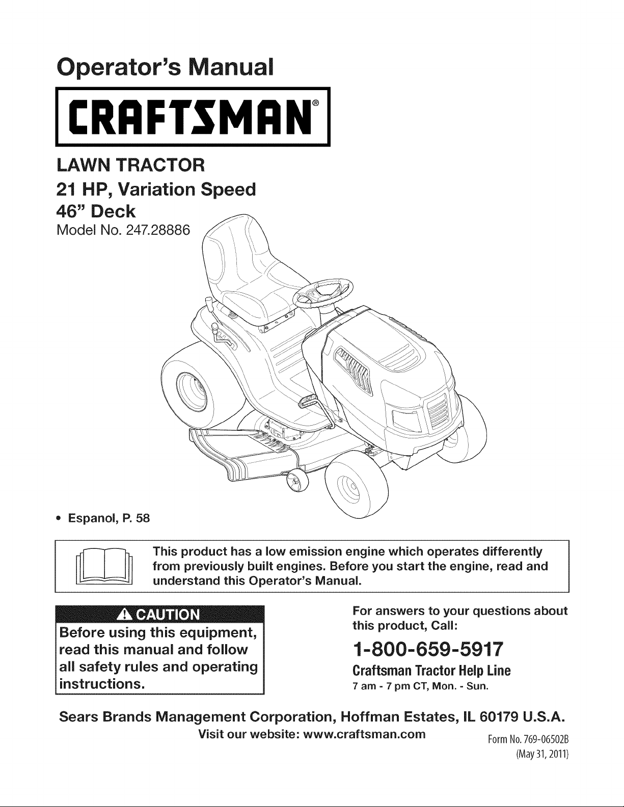
LAWN TRACTOR
21 HP, Variation Speed
46" Deck
Model No. 247.28886
• Espanol, P. 58
This product has a low emission engine which operates differently
from previously built engines. Before you start the engine, read and
understand this Operator's Manual.
Before using this equipment,
read this manual and follow
all safety rules and operating
instructions.
For answers to your questions about
this product, Call:
1-800=659=5917
Craftsman Tractor Help Line
7 am = 7 pm CT, Mort. =Sun.
Sears Brands Management Corporation, Hoffman Estates, IL 60179 U.S.A.
Visit our website: www.craftsman.com FormNo.769-06502B
(May31,2011)
Off-Season Storage ........................................................ 27
Trou bleshooting .............................................................. 28
Labels ............................................................................. 29
Parts List ......................................................................... 30
Espafiol ............................................................................ 58
Service Numbers ............................................. Back Cover
CRAFTSMAN FULL WARRANTY
FORTWOYEARSfromthe date of purchase,all non-expendablepartsof thisridingequipmentarewarrantedagainstany defectsin matedal
or workmanship.A defectivenon-expendablepart will receivefree in-homerepairor replacementif repairis impossible.
FORFIVEYEARSfromthe dateof purchase,the frameandfrontaxleof thisridingequipmentarewarrantedagainstanydefectsinmaterialor
workmanship.A defectiveframeor frontaxle will receivefreein-homerepairor replacementif repairis impossible.
FOR90 DAYSfromthe dateof purchase,the battery(an expendablepart)of this ridingequipmentis warrantedagainstanydefectsin material
or workmanship(ourtestingprovesthat it will not holda charge).A defectivebatterywill receivefreein-homereplacement.
ADDITIONALLIFETIMELIMITEDWARRANTYon CASTIRON FRONTAXLE (if equipped)
FORAS LONGASIT IS USEDby the originalownerafterthe fifth yearfromthedate of purchase,the cast ironfrontaxle (if equipped)of this
ridingequipmentis warrantedagainstanydefectsin materialorworkmanship.Withproofof purchase,a defectivecastfrontaxle will receive
free in-homereplacement.
WARRANTYSERVICE
Forwarrantycoveragedetailsto obtainfree repairor replacement,call 1-800-659-5917or visit theweb site:www. craftsman.corn
inallcasesabove,if partrepairor replacementis impossible,theridingequipmentwillbereplacedfreeof chargewiththe sameor anequivalentmodel.
All of the abovewarrantycoverageis voidif this ridingequipmentis ever usedwhileprovidingcommercialservicesor if rentedto another
person.
This warranty covers ONLYdefects in material and workmanship. Warranty coverage does NOTinclude:
• Expendableparts(exceptbattery)that can wearout fromnormaluse withinthe warrantyperiod,includingbutnot limitedto blades,
sparkplugs,air cleaners,belts,andoilfilters.
• Standardmaintenanceservicing,oil changes,ortune-ups.
• Tire replacementor repaircausedby puncturesfromoutsideobjects,suchas nails,thorns,stumps,or glass.
• Tire orwheel replacementor repairresultingfromnormalwear,accident,or improperoperationor maintenance.
• Repairsnecessarybecauseof operatorabuse,includingbutnot limitedto damagecausedbytowingobjectsbeyondthe capabilityof
the ridingequipment,impactingobjectsthat bendthe frame,axle assemblyor crankshaft,orover-speedingtheengine.
• Repairsnecessarybecauseof operatornegligence,includingbut not limitedto, electricalandmechanicaldamagecaused by
improperstorage,failureto use the propergradeand amountof engineoil, failureto keepthedeckclear of flammabledebris,or
failureto maintainthe ridingequipmentaccordingto the instructionscontainedinthe operator'smanual.
• Engine(fuelsystem)cleaningor repairscausedby fueldeterminedto becontaminatedor oxidized(stale).In general,fuel shouldbe
usedwithin30 daysof its purchasedate.
• Normaldeteriorationand wearof the exteriorfinishes,or productlabelreplacement.
Thiswarrantygivesyou specificlegalrights,and you mayalso haveotherrightswhichvary fromstateto state.
Sears Brands ManagementCorporation, Hoffman Estates, IL 60179
EngineOil: SAE30
Fuel: UnleadedGasoline
SparkPlug: Champion®RC12YC
Engine: Briggs& Stratton
© KCD IR LLC
Model Number:
Serial Number:
Dateof Purchase:
Recordthe modelnumber,serialnumber,
anddateof purchaseabove.
2
Thissymbolpointsout importantsafetyinstructionswhich,if not
followed,couldendangerthepersonalsafetyand/orpropertyof
yourselfandothers. Readand followall instructionsin thismanual
beforeattemptingto operatethis machine.Failureto complywith
theseinstructionsmayresultin personalinjury.Whenyou seethis
symbol,HEEDITSWARNING!
CALIFORNIA PROPOSITION 65
EngineExhaust,someof its constituents,andcertainvehicle
componentscontainor emitchemicalsknownto Stateof California
to causecancerandbirthdefectsorother reproductiveharm.
Batteryposts,terminals,and relatedaccessoriescontainleadand
leadcompounds,chemicalsknownto the Stateof Californiato
causecancerand reproductiveharm.Washhandsafterhandling.
Thismachinewasbuiltto beoperatedaccordingto the safeopera-
tion practicesinthis manual.As with anytypeof powerequipment,
carelessnessorerroron the partof the operatorcan resultin serious
injury.Thismachineis capableof amputatingfingers,hands,toes
andfeet andthrowingdebris.Failureto observethe followingsafety
instructionscouldresultin seriousinjuryor death.
Your Responsibility--Restrictthe use of thispowermachineto
personswho read,understandand followthewarningsand instruc-
tionsin this manualandon the machine.
SAVE THESE INSTRUCTIONS!
GENERAL OPERATION
• Read,understand,andfollowall instructionson the machineand
in themanual(s)beforeattemptingto assembleand operate.
Keepthis manualina safe placefor futureand regularreference
andfor orderingreplacementparts.
• Befamiliarwithall controlsand their properoperation.Knowhow
to stopthe machineand disengagethemquickly.
• Neverallowchildrenunder 14yearsold to operatethis machine.
Children14yearsoldandover shouldreadandunderstandthe
operationinstructionsandsafetyrulesin thismanualand should
betrainedandsupervisedbya parent.
• Neverallowadultsto operatethis machinewithoutproper
instruction.
• Tohelpavoidbladecontactor a thrownobjectinjury, keep
bystanders,helpers,childrenandpets at least 75feet fromthe
machinewhile it is in operation.Stopmachineif anyoneenters
the area.
• Thoroughlyinspectthe areawherethe equipmentis to be used.
Removeallstones,sticks,wire,bones,toys,andotherforeign
objectswhichcouldbe pickedup andthrownby the blade(s).
Thrownobjectscan causeseriouspersonalinjury.
• Planyour mowingpatternto avoiddischargeof materialtoward
roads,sidewalks,bystandersandthe like.Also,avoiddischarg-
ingmaterialagainstawall orobstructionwhichmaycause
dischargedmaterialto ricochetback towardthe operator.
• Alwayswear safetyglassesor safetygogglesduringoperation
andwhile performingan adjustmentor repairto protectyoureyes.
Thrownobjectswhichricochetcancause seriousinjuryto the
eyes.
• Wearsturdy,rough-soledwork shoesandclose-fittingslacksand
shirts.Loosefittingclothesandjewelrycanbe caughtin movable
parts.Neveroperatethismachinein barefeet orsandals.
• Be awareof the mowerand attachmentdischargedirectionand
do not pointit at anyone.Donot operatethe mowerwithoutthe
dischargecover orentiregrass catcherin its properplace.
Donot put handsor feet nearrotatingpartsor underthe cutting
deck. Contactwiththe blade(s)can amputatehandsandfeet.
A missingor damageddischargecovercan causeblade contact
or thrownobjectinjuries.
• Stoptheblade(s)whencrossinggraveldrives,walks,or roads
andwhile notcuttinggrass.
• Watchfor trafficwhenoperatingnearor crossingroadways.This
machineis not intendedfor useon any public roadway.
• Donot operatethe machinewhile underthe influenceof alcohol
or drugs.
• Mowonly indaylightorgoodartificiallight.
Nevercarrypassengers.
• Disengageblade(s)beforeshiftinginto reverse.Backup slowly.
Alwayslookdownandbehindbeforeandwhile backingto avoida
back-overaccident.
3
• Slowdownbeforeturning.Operatethe machinesmoothly.Avoid
erraticoperationandexcessivespeed.
Disengageblade(s),set parkingbrake,stopengineand waituntil
the blade(s)cometo a completestopbeforeremovinggrass
catcher,emptyinggrass,uncloggingchute,removinganygrassor
debris,or makinganyadjustments.
Neverleavea runningmachineunattended.Alwaysturnoff
blade(s),setparkingbrake,stopengine andremovekeybefore
dismounting.
Useextracare whenloadingorunloadingthe machineintoa
trailerortruck.Thismachineshouldnot bedrivenup or down
ramp(s),becausethe machinecouldtip over,causingserious
personalinjury.The machinemustbe pushedmanuallyon
ramp(s)to loador unloadproperly.
Mufflerandenginebecomehotandcan causea burn.Do not
touch.
Checkoverheadclearancescarefullybeforedrivingunderlow
hangingtree branches,wires,door openingsetc.,wherethe
operatormaybestruckor pulledfromthe machine,which could
resultinseriousinjury.
Disengageall attachmentclutchesanddepressthe brakepedal
completelybeforeattemptingto start engine.
Yourmachineisdesignedto cutnormalresidentialgrass of a
heightnomorethan 10".Do not attemptto mowthroughunusually
tall,dry grass(e.g.,pasture)or piles of dry leaves.Drygrassor
leavesmaycontactthe engineexhaustand/or build upon the
mowerdeckpresentinga potentialfire hazard.
Useonlyaccessoriesandattachmentsapprovedfor this machine
by the machinemanufacturer.Read,understandandfollowall
instructionsprovidedwiththe approvedaccessoryor attachment.
Fora list of approvedaccessoriesandattachments,call 1-800-
659-5917.
Dataindicatesthatoperators,age60yearsandabove,are
involvedin a largepercentageof ridingmower-relatedinjuries.
Theseoperatorsshouldevaluatetheirabilityto operatethe riding
mowersafelyenoughto protectthemselvesand othersfrom
seriousinjury.
If situationsoccurwhich arenot coveredinthismanual,usecare
andgoodjudgment.Contact1-800-659-5917for informationand
assistance.
SLOPE OPERATION
Slopesarea majorfactorrelatedto lossof controlandtip-over
accidentswhichcan result insevereinjuryor death.Allslopes require
extracaution.If youcannotbackupthe slopeor if youfeel uneasyon
it, do not mowit.
Foryoursafety,use the SlopeGuide includedas partof this manual
to measureslopesbeforeoperatingthis machineona slopedor hilly
area. If the slopeis greaterthan15degreesas shownonthe Slope
Guide,do notoperatethis machineonthat areaor seriousinjurycould
result.
Do:
o
Mowupand down slopes,not across.Exerciseextremecaution
whenchangingdirectionon slopes.
• Watchfor holes,ruts,bumps,rocks,orother hiddenobjects.
Uneventerraincouldoverturnthe machine.Tallgrasscan hide
obstacles.
Useslowspeed.Choosea lowenoughspeedsettingso that
you will nothaveto stopor shiftwhileon the slope.Tiresmay
lose tractionon slopeseventhoughthe brakesarefunctioning
properly.Alwayskeepmachinein gearwhen goingdownslopes
to takeadvantageof enginebrakingaction.
• Followthe manufacturer'srecommendationsfor wheelweights
or counterweightsto improvestability.Forrecommendations,call
1-800-659-5917.
• Useextra carewithgrass catchersor otherattachments.These
can changethe stabilityof the machine.
Keepallmovementonthe slopesslowandgradual.Do not make
suddenchangesinspeedor direction.Rapidengagementor
brakingcouldcausethe frontof the machineto lift and rapidlyflip
overbackwardswhichcouldcauseseriousinjury.
• Avoidstartingorstoppingona slope.Iftireslosetraction,disen-
gagethe blade(s)andproceedslowlystraightdownthe slope.
DoNot:
• Donot turnon slopesunlessnecessary;then,turnslowlyand
graduallydownhill,if possible.
• Donot mowneardrop-offs,ditchesor embankments.The mower
could suddenlyturnover if a wheelis overthe edgeof a cliff,
ditch,or if an edge cavesin.
• Donot try to stabilizethe machineby puttingyourfooton the
ground.
• Donot usea grasscatcheron steepslopes.
• Donot mowon wetgrass.Reducedtractioncouldcausesliding.
• Donot attemptto coastdownhill.Over-speedingmaycausethe
operatorto lose controlof the machineresultingin seriousinjury
or death.
• Donot towheavypull behindattachments(e.g. loadeddumpcart,
lawn roller,etc.)on slopesgreaterthan5 degrees.Whengoing
down hill,the extraweighttendsto pushthe tractorand may
causeyou to loosecontrol(e.g.tractormayspeedup, brakingand
steeringabilityare reduced,attachmentmayjack-knifeandcause
tractorto overturn).
4
CHILDREN
Tragicaccidentscanoccurifthe operatoris notalert to the presence
of children.Childrenareoftenattractedto the machineand the mowing
activity.Theydo notunderstandthe dangers.Neverassumethat
childrenwill remainwhereyou lastsawthem.
• Keepchildrenout of the mowingareaand inwatchfulcare of a
responsibleadultotherthanthe operator.
• Bealert andturnmachineoff ifa childentersthe area.
• Beforeand whilebacking,lookbehindanddownfor small
children.
Nevercarrychildren,evenwiththe blade(s)shutoff.Theymay
fall offandbe seriouslyinjuredorinterferewithsafemachine
operation.
• Useextremecarewhenapproachingblindcorners,doorways,
shrubs,treesorotherobjectsthatmayblockyourvisionof a child
whomayrunintothe machine.
Toavoidback-overaccidents,alwaysdisengagethe cutting
blade(s)beforeshiftingintoReverse.Ifequipped,the "Reverse
CautionMode"(bladesoperatewhilemachineridesin reverse)
shouldnotbe usedwhenchildrenor othersarearound.
Keepchildrenawayfromhotor runningengines.Theycansuffer
burnsfroma hotmuffler.
• Removekeywhenmachineisunattendedto preventunauthorized
operation.
Neverallowchildrenunder14yearsof ageto operatethis machine.
Children14andovershouldreadandunderstandthe instructionsand
safeoperationpracticesin thismanualandon the machineand should
betrainedandsupervisedbyan adult.
TOWING
Towonlywitha machinethathasa hitch designedfor towing.Do
not attachtowedequipmentexceptat the hitchpoint.
Followthe manufacturersrecommendationforweight limitsfor
towedequipmentand towingonslopes.For recommendations,
call 1-800-659-5917.
Neverallowchildrenor othersinoron towedequipment.
Onslopes,theweightof thetowedequipmentmaycauselossof
tractionandlossof control.
Alwaysuseextracautionwhentowingwitha machinecapableof
makingtightturns (e.g."zero-turn"ride-onmower). Makewide
turnsto avoidjack-knifing.
Travelslowlyandallowextradistanceto stop.
Do notcoastdownhill.
SERVICE
SafeHandlingof Gasoline
Toavoidpersonalinjuryor propertydamageuse extremecarein
handlinggasoline.Gasolineisextremelyflammableandthe vaporsare
explosive.Seriouspersonalinjurycanoccur whengasolineis spilled
on yourselforyour clotheswhich can ignite.Washyourskinand
changeclothesimmediately.
• Useonly anapprovedgasolinecontainer.
Neverfill containersinsidea vehicleor on a truckortrailer bed
witha plasticliner.Alwaysplacecontainerson the groundaway
fromyourvehiclebeforefilling.
Whenpractical,removegas-poweredequipmentfromthe truck
or trailerandrefueliton theground.If this isnot possible,then
refuelsuchequipmentona trailerwith a portablecontainer,rather
than froma gasolinedispensernozzle.
Keepthe nozzleincontactwith the rim of the fueltank or
containeropeningat all timesuntilfuelingiscomplete.Donot use
a nozzlelock-opendevice.
Extinguishall cigarettes,cigars,pipesandothersourcesof
ignition.
• Neverfuel machineindoors.
Neverremovegascap or add fuelwhilethe engineis hotor run-
ning.Allowengineto coolat leasttwo minutesbeforerefueling.
Neveroverfill fuel tank. Filltankto no morethan 1/2inchbelow
bottomof filler neckto allowspaceforfuel expansion.
• Replacegasolinecap andtightensecurely.
• If gasolineis spilled,wipeitoff the engineandequipment.Move
machineto anotherarea.Wait 5 minutesbeforestartingthe
engine.
• To reducefire hazards,keepmachinefree of grass,leaves,or
otherdebrisbuild-up.Cleanup oilor fuel spillageandremoveany
fuel soakeddebris.
• Neverstorethe machineor fuelcontainerinsidewherethere isan
openflame,sparkor pilotlight as ona waterheater,spaceheater,
furnace,clothesdryeror othergasappliances.
Allowa machineto coolat least fiveminutesbeforestoring.
GeneralService
• Neverrunanengineindoorsorinapoorlyventilatedarea.Engine
exhaustcontainscarbonmonoxide,anodorless,anddeadlygas.
• Beforecleaning,repairing,orinspecting,makecertainthe
blade(s)andallmovingpartshavestopped.Disconnectthespark
plugwireandgroundagainsttheenginetopreventunintended
starting.
• Periodicallychecktomakesurethebladescometocomplete
stopwithinapproximately(5)fivesecondsafteroperatingthe
bladedisengagementcontrol.Ifthebladesdonotstopwithinthe
thistimeframe,yourmachineshouldbeservicedprofessionally
byaSearsorotherqualifiedservicedealer.
• Checkbrakeoperationfrequentlyasitissubjectedtowearduring
normaloperation.Adjustandserviceasrequired.
• Checktheblade(s)andenginemountingboltsatfrequent
intervalsforpropertightness.Also,visuallyinspectblade(s)
fordamage(e.g.,excessivewear,bent,cracked).Replacethe
blade(s)withtheoriginalequipmentmanufacturer's(O.E.M.)
blade(s)only,listedinthismanual.Useofpartswhichdonot
meettheoriginalequipmentspecificationsmayleadtoimproper
performanceandcompromisesafety!
• Mowerbladesaresharp.Wrapthebladeorweargloves,anduse
extracautionwhenservicingthem.
• Keepallnuts,bolts,andscrewstighttobesuretheequipmentis
insafeworkingcondition.
• Nevertamperwiththe safetyinterlocksystemor othersafety
devices.Checktheir properoperationregularly.
• Afterstrikinga foreignobject,stopthe engine,disconnectthe
sparkplugwire(s)andgroundagainstthe engine.Thoroughly
inspectthe machinefor anydamage.Repairthe damagebefore
startingandoperating.
• Neverattemptto makeadjustmentsor repairsto the machine
whilethe engineis running.
• Grasscatchercomponentsandthe dischargecoverare subject
to wearanddamagewhich couldexposemovingparts or allow
objectsto bethrown.Forsafetyprotection,frequentlycheck
componentsand replaceimmediatelywithoriginalequipment
manufacturer's(O.E.M.)partsonly,listed inthis manual.Useof
partswhichdo not meetthe originalequipmentspecificationsmay
leadto improperperformanceand compromisesafety!
• Donot changethe enginegovernorsettingsorover-speedthe
engine.The governorcontrolsthe maximumsafe operatingspeed
of the engine.
Maintainor replacesafetyandinstructionlabels,as necessary.
• Observeproperdisposallawsandregulationsfor gas,oil, etc.to
protecttheenvironment.
• Accordingto the ConsumerProductsSafetyCommission(CPSC)
andthe U.S.EnvironmentalProtectionAgency(EPA),this product
has anAverageUsefulLifeof seven(7)years,or 270hours
of operation.At the end of the AverageUsefulLife,buy anew
machineor havethe machineinspectedannuallybya Searsor
otherqualifiedservicedealerto ensurethat all mechanicaland
safetysystemsareworkingproperlyand not wornexcessively.
Failureto doso can resultin accidents,injuriesor death.
DO NOT MODIFY ENGINE
Toavoid seriousinjuryor death,do notmodifyengineinanyway.
Tamperingwiththe governorsettingcanlead to a runawayengineand
causeit to operateat unsafespeeds.Nevertamperwith factorysetting
of enginegovernor.
NOTICE REGARDING EMISSIONS
Engineswhicharecertifiedto complywith Californiaand federal
EPAemissionregulationsfor SORE(SmallOffRoadEquipment)are
certifiedto operateon regularunleadedgasoline,andmay include
the followingemissioncontrol systems:EngineModification(EM)and
ThreeWayCatalyst(TWO)if so equipped.
SPARK ARRESTOR
Thismachineis equippedwithan internalcombustionengineand
shouldnotbe usedonor nearanyunimprovedforest-covered,
brushcoveredor grass-coveredland unlessthe engine'sexhaust
systemisequippedwitha sparkarrestormeetingapplicablelocalor
statelaws(if any).
Ifa sparkarrestoris used,it shouldbe maintainedin effectiveworking
orderby the operator.Inthe Stateof Californiatheaboveis required
by law (Section4442of the CaliforniaPublicResourcesCode). Other
statesmayhavesimilarlaws.Federallaws applyonfederallands.
A sparkarrestorfor the muffleris availablethroughyournearestSears
PartsandRepairServiceCenter.
6
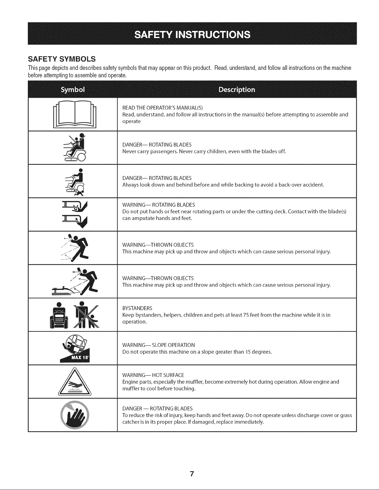
SAFETY SYMBOLS
Thispagedepictsanddescribessafety symbolsthat mayappearon this product. Read,understand,andfollowallinstructionson the machine
beforeattemptingto assembleand operate.
O
A
READ THE OPERATOR'S MANUAL(S)
Read, understand, and follow all instructions in the manual(s) before attempting to assemble and
operate
DANGER-- ROTATING BLADES
Never carry passengers. Never carry children, even with the blades off.
DANGER-- ROTATING BLADES
Always look down and behind before and while backing to avoid a back-over accident.
WARNING-- ROTATING BLADES
Do not put hands or feet near rotating parts or under the cutting deck. Contact with the blade(s)
can amputate hands and feet.
WARNING--THROWN OBJECTS
This machine may pick up and throw and objects which can cause serious personal injury.
WARNING--THROWN OBJECTS
This machine may pick up and throw and objects which can cause serious personal injury.
BYSTANDERS
Keep bystanders, helpers, children and pets at least 75 feet from the machine while it is in
operation.
WARNING-- SLOPE OPERATION
Do not operate this machine on a slope greater than 15 degrees.
WARNING-- HOT SURFACE
Engine parts, especially the muffler, become extremely hot during operation. Allow engine and
muffler to cool before touching.
DANGER- ROTATING BLADES
To reduce the risk of injury, keep hands and feet away. Do not operate unless discharge cover or grass
catcher is in its proper place. If damaged, replace immediately.
7
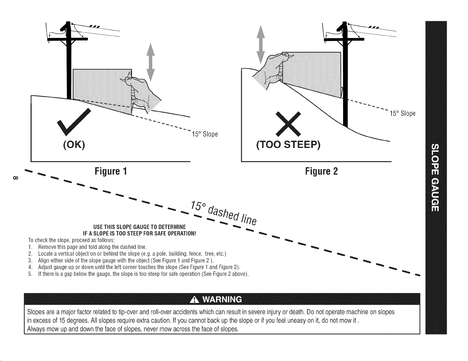
(OK)
15° Slope
X
(TOO STEEP)
15° Slope
'_. _ Figure1
USETHISSLOPEGAUGETODETERMINE
IFA SLOPEIS TOOSTEEPFORSAFEOPERATION!
To checkthe slope,proceedas follows:
1. Removethis pageandfold alongthe dashedline.
2. Locatea verticalobject onor behindthe slope (e.g.a pole, building,fence, tree,etc.)
3. Align eitherside of the slope gaugewith the object(See Figure1 and Figure2 ).
4. Adjust gaugeup or down until the left cornertouchesthe slope (SeeFigure1 and Figure2).
5.
15°
dashed line
If there is agap belowthe gauge,the slope is too steepfor safeoperation(SeeFigure2 above).
Figure2
Slopes are a majorfactor related to tip-over and roll-over accidents which can result in severe injury or death. Do not operate machine on slopes
in excess of 15 degrees. All slopes require extra caution. If you cannot back up the slope or if you feel uneasy on it, do not mow it.
Always mow up and down the face of slopes, never mow across the face of slopes.
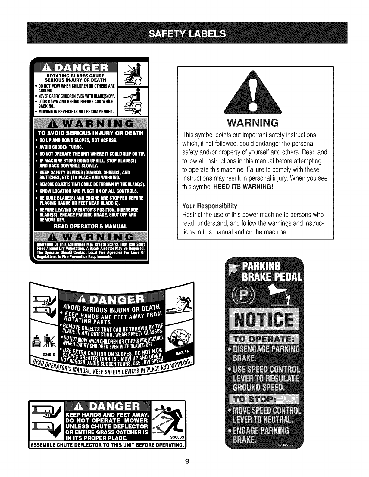
ROTATING BLADES CAUSE
SERIOUS INJURY OR DEATH
DONOTMOWWHENCHILDRENOROTHERSARE
AROUND
NEVERCARRYCHILDRENEVENWITHBLADE(S)OFF.
LOOKDOWNANDBEHINDBEFOREANDWHILE
BACKING.
MOWINGINREVERSEISNOTRECOMMENDED.
WARNING
This symbol points out important safety instructions
which, if notfollowed, could endangerthe personal
safety and/or property of yourself and others. Read and
follow all instructions inthis manualbefore attempting
to operatethis machine. Failure to comply with these
instructions may result in personal injury.When you see
this symbol HEED ITS WARNING!
Your Responsibility
Restrictthe use of this power machineto persons who
read, understand, and follow the warnings and instruc-
tions in this manual and on the machine.
9
IMPORTANT:Yourtractoris shippedwithmotoroil in theengine.
However,you MUSTcheckthe oil levelbeforeoperating.Referto the
Service& Maintenancesectionfor instructionson checkingtheoil
level.
Attaching the Battery Cables
CALIFORNIA PROPOSITION 65
Batteryposts,terminals,andrelatedaccessoriescontainlead and
leadcompounds,chemicalsknownto the Stateof Californiato
causecancerand reproductiveharm.Washhandsafter handling.
Whenattachingbatterycables,alwaysconnectthe POSITIVE(Red)
wireto its terminalfirst,followedby the NEGATIVE(Black)wire.
Forshippingreasons,bothbatterycables onyourequipmenthave
beenleft disconnectedfromthe terminalsat the factory.Toconnect
the batterycables,proceedas follows:
NOTE:Thepositivebatteryterminalis markedPos.(+).The negative
batteryterminalis markedNeg. (i).
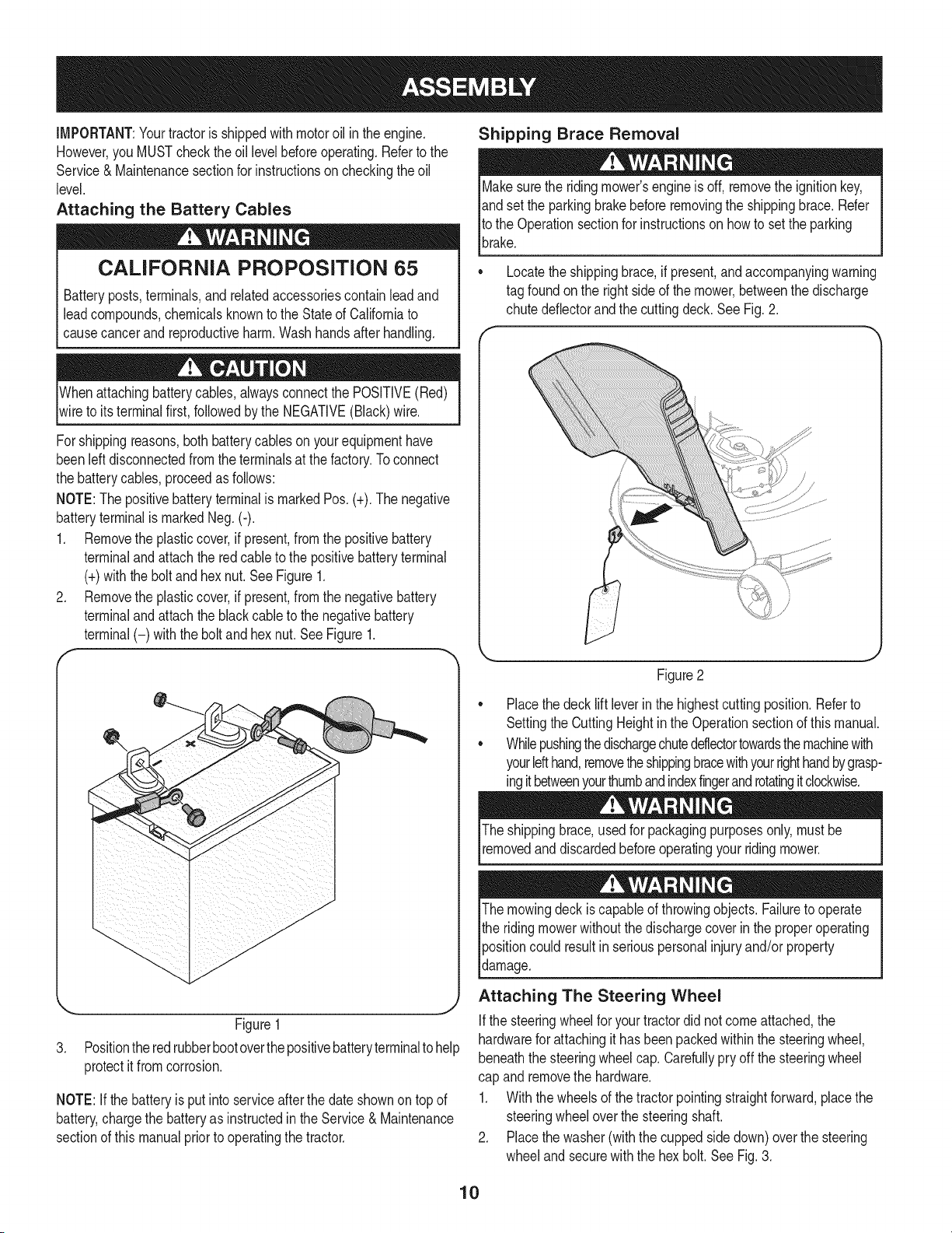
1. Removethe plasticcover,if present,fromthe positivebattery
terminaland attachthe redcableto the positivebatteryterminal
(+)withthe bolt andhexnut.See Figure1.
2. Removethe plasticcover,if present,fromthe negativebattery
terminaland attachthe black cableto the negativebattery
terminal(-) withthe bolt andhex nut.See Figure1.
f
J
Figure1
3. Positionthe redrubberbootoverthepositivebatteryterminalto help
protectit fromcorrosion.
NOTE:If thebatteryis put into serviceafterthe dateshownon topof
battery,chargethe batteryas instructedinthe Service& Maintenance
sectionof this manualpriorto operatingthe tractor.
Shipping Brace Removal
Makesurethe ridingmower'sengineis off, removetheignitionkey,
andset the parkingbrakebeforeremovingthe shippingbrace.Refer
Itothe Operationsectionfor instructionsonhowto setthe parking
lbrake.
• Locatethe shippingbrace,if present,andaccompanyingwarning
tag foundonthe rightsideof the mower,betweenthe discharge
chutedeflectorandthe cuttingdeck. SeeFig. 2.
Figure2
Placethe decklift leverin the highestcuttingposition.Referto
SettingtheCuttingHeightin the Operationsectionof this manual.
Whilepushingthedischargechuteddlectortowardsthemachinewith
yourlefthand,removetheshippingbracewithyourrighthandbygrasp-
ingitbetweenyourthumbandindexfingerandrotatingitclockwise.
The shippingbrace,usedfor packagingpurposesonly,mustbe
removedand discardedbeforeoperatingyour ridingmower.
The mowingdeck iscapableof throwingobjects. Failureto operate
the ridingmowerwithoutthe dischargecoverin the properoperating
Ipositioncould resultin seriouspersonalinjuryand/orproperty
ldamage.
Attaching The Steering Wheel
Ifthe steeringwheelfor yourtractordid notcomeattached,the
hardwarefor attachingit has beenpackedwithinthe steeringwheel,
beneaththe steeringwheelcap.Carefullypry off the steeringwheel
cap andremovethe hardware.
1. Withthe wheelsof the tractorpointingstraightforward,placethe
steeringwheeloverthe steeringshaft.
2. Placethe washer(withthe cuppedsidedown)overthe steering
wheeland securewiththe hex bolt. SeeFig.3.
10
f
\
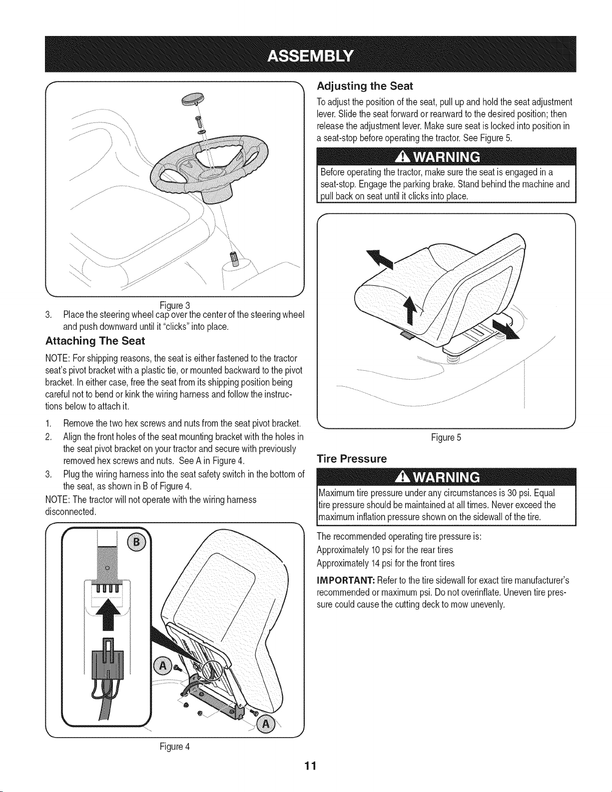
Figure3
3. Placethe steeringwheelcap overthe centerof the steeringwheel
andpushdownwarduntil it "clicks"into place.
Attaching The Seat
NOTE:Forshippingreasons,the seatis eitherfastenedtothe tractor
seat'spivotbracketwitha plastictie, or mountedbackwardto the pivot
bracket.Ineithercase,free the seatfromits shippingpositionbeing
carefulnotto bendor kinkthe wiringharnessandfollow theinstruc-
tionsbelowto attach it.
1. Removethetwo hexscrewsandnutsfromthe seatpivot bracket.
2. Alignthefront holesof the seatmountingbracketwith the holesin
the seat pivotbracketon yourtractorand securewith previously
removedhex screwsandnuts. See A in Figure4.
3. Plugthe wiringharnessintothe seatsafetyswitchinthe bottomof
the seat,as shownin B of Figure4.
NOTE:The tractorwill not operatewith the wiringharness
disconnected.
Adjusting the Seat
Toadjustthe positionof the seat,pull upand holdthe seatadjustment
lever.Slidethe seatforwardor rearwardto thedesiredposition;then
releasethe adjustmentlever.Makesure seatis lockedintopositionin
a seat-stopbeforeoperatingthe tractor.SeeFigure5.
Beforeoperatingthe tractor,makesurethe seat is engagedin a
seat-stop.Engagethe parkingbrake.Standbehindthe machineand
pull backon seatuntil it clicksintoplace.
Figure5
Tire Pressure
Maximumtire pressureunderany circumstancesis 30 psi.Equal
tire pressureshouldbe maintainedat all times.Neverexceedthe
_maxmum nfat onpressureshownonthe s dewa of thet re.
The recommendedoperatingtire pressureis:
Approximately10psi forthe reartires
Approximately14psi forthe fronttires
iMPORTANT: Referto the tire sidewallfor exacttire manufacturer's
recommendedor maximumpsi.Donot overinfiate.Uneventirepres-
surecouldcausethe cuttingdeckto mowunevenly.
Figure4
11
B
C
D
E
G
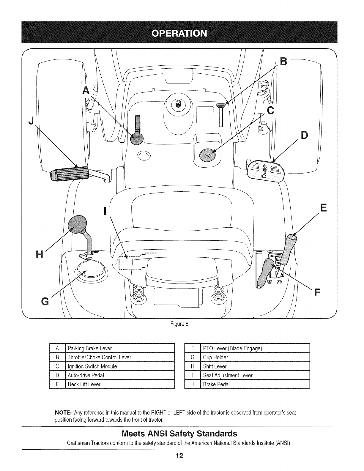
Figure6
F
J
A ParkingBrakeLever
B Throttle/ChokeControlLever
C IgnitionSwitchModule
D Auto-drivePedal
E DeckLift Lever
F PTOLever(BladeEngage)
G Cup Holder
H ShiftLever
I SeatAdjustmentLever
J BrakePedal
NOTE: Any referencein this manualto the RIGHTor LEFTsideof the tractoris observedfromoperator'sseat
positionfacingforwardtowardsthe frontof tractor.
Meets ANSi Safety Standards
CraftsmanTractorsconformto the safetystandardof theAmericanNationalStandardsInstitute(ANSI).
12
PARKING BRAKE LEVER
Toset the parkingbrake: Fullydepressthe brakepedal. Movethe
parkingbrakeleverintothe parkingbrakeposition.Releasethe brake
pedalto allowthe parkingbraketo engage.
To release the parkingbrake: Depressthe brakepedalandthe park-
ingbrakeleverwill moveoutof the parkingbrakepositionon its own.
Theparkingbrakewillthen bereleased.Releasethe brakepedal.
NOTE=The parkingbrakemustbe setif the operatorleavesthe seat
withthe enginerunningor the enginewill automaticallyshutoff.
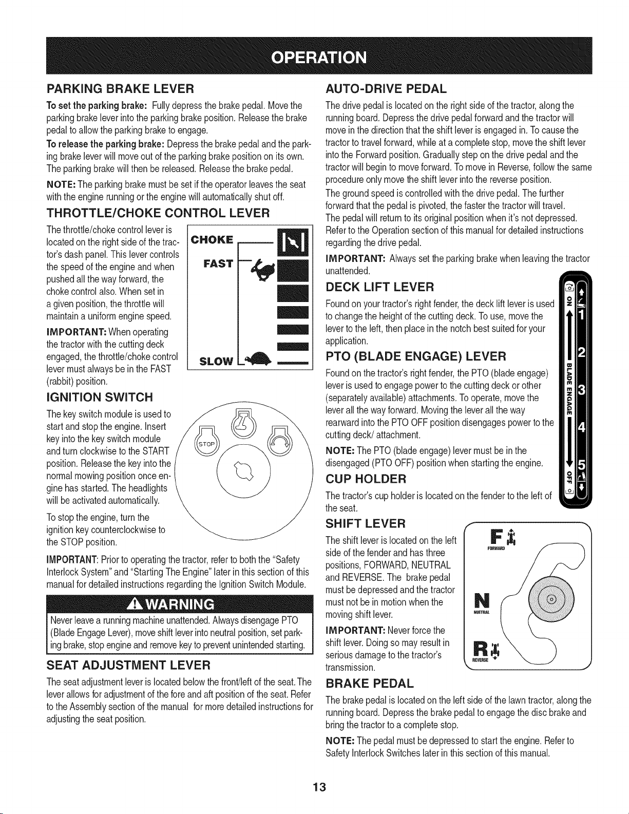
THROTTLE/CHOKE CONTROL LEVER
Thethrottle/chokecontrolleveris
locatedonthe right sideof the trac-
tor'sdash panel.This levercontrols
the speedof the engineand when
pushedall thewayforward,the
chokecontrolalso.Whenset in
a givenposition,thethrottlewill
maintaina uniformenginespeed.
IMPORTANT= Whenoperating
the tractorwiththe cuttingdeck
engaged,thethrottle/chokecontrol
levermustalwaysbe inthe FAST
(rabbit)position.
IGNITION SWITCH
Thekeyswitchmoduleisusedto
startand stopthe engine.Insert
keyintothe keyswitchmodule
andturnclockwiseto theSTART
position.Releasethe keyintothe
normalmowingpositiononceen-
ginehasstarted.The headlights
will beactivatedautomatically.
Tostopthe engine,turnthe
ignitionkeycounterclockwiseto
the STOPposition.
CHOKE
FAST
SLOW
l=, m
IMPORTANT:Prior to operatingthe tractor,referto boththe "Safety
InterlockSystem"and"StartingThe Engine"laterinthissectionof this
manualfor detailedinstructionsregardingthe IgnitionSwitchModule.
Neverleavea runningmachineunattended.AlwaysdisengagePTO
(BladeEngageLever),moveshiftleverintoneutralposition,setpark-
ingbrake,stopengineandremovekeyto preventunintendedstarting.
SEAT ADJUSTMENT LEVER
Theseatadjustmentleveris locatedbelowthe front/leftof the seat.The
leverallowsfor adjustmentof the foreandaft positionof the seat.Refer
to theAssemblysectionof themanual formoredetailedinstructionsfor
adjustingthe seatposition.
AUTO-DRIVE PEDAL
The drivepedalislocatedonthe rightside of the tractor,alongthe
runningboard.Depressthe drivepedalforwardandthe tractorwill
moveinthe directionthatthe shiftleveris engagedin. Tocausethe
tractorto travelforward,whileat a completestop,movethe shift lever
intothe Forwardposition.Graduallystepon the drivepedaland the
tractorwill beginto moveforward.Tomovein Reverse,followthe same
procedureonlymovetheshift leverintothe reverseposition.
The groundspeediscontrolledwiththe drivepedal.Thefurther
forwardthatthe pedalis pivoted,thefasterthe tractorwill travel.
The pedalwill returnto itsoriginalpositionwhenit'snot depressed.
Referto the Operationsectionof thismanualfor detailedinstructions
regardingthedrive pedal.
IMPORTANT= Alwayssetthe parkingbrakewhenleavingthe tractor
unattended.
DECK LIFT LEVER
Foundonyour tractor'srightfender,the deckliftleveris used
to changethe heightof the cuttingdeck.To use,movethe
leverto the left, thenplaceinthe notchbestsuitedfor your
application.
PTO (BLADE ENGAGE) LEVER
Foundonthe tractor'srightfender,the PTO(bladeengage)
leveris usedto engagepowerto the cuttingdeckor other
(separatelyavailable)attachments.Tooperate,movethe
leverall thewayforward.Movingthe leverallthe way
rearwardintothe PTOOFFpositiondisengagespowerto the
cuttingdeck/attachment.
NOTE=The PTO(bladeengage)levermustbein the
disengaged(PTOOFF)positionwhenstartingthe engine.
CUP HOLDER
The tractor'scup holderis locatedon the fenderto the left of
the seat.
SHIFT LEVER
The shift leveris locatedonthe left
sideof the fenderand hasthree
positions,FORWARD,NEUTRAL
and REVERSE.The brakepedal
mustbedepressedandthe tractor
mustnotbe in motionwhenthe
movingshift lever.
IMPORTANT: Neverforcethe
shiftlever.Doingso mayresultin
seriousdamageto the tractor's
transmission.
REVERSE
_J
BRAKE PEDAL
The brakepedalis locatedon the leftside of the lawntractor,alongthe
runningboard.Depressthe brakepedalto engagethe discbrakeand
bringthe tractorto a completestop.
NOTE: Thepedalmustbedepressedto startthe engine.Referto
SafetyInterlockSwitcheslaterin thissectionof thismanual.
13
GAS AND OiL FILL-UP
0il
iMPORTANT: Yourtractorisshippedwith motoroilin the engine.
However,you MUSTcheckthe oil levelbeforeoperating.Becareful
notto overfill.
Forinstructionsonhowto checkthe engineoil, referto CheckingThe
EngineOilin the Serviceand Maintenancesectionof this manual.
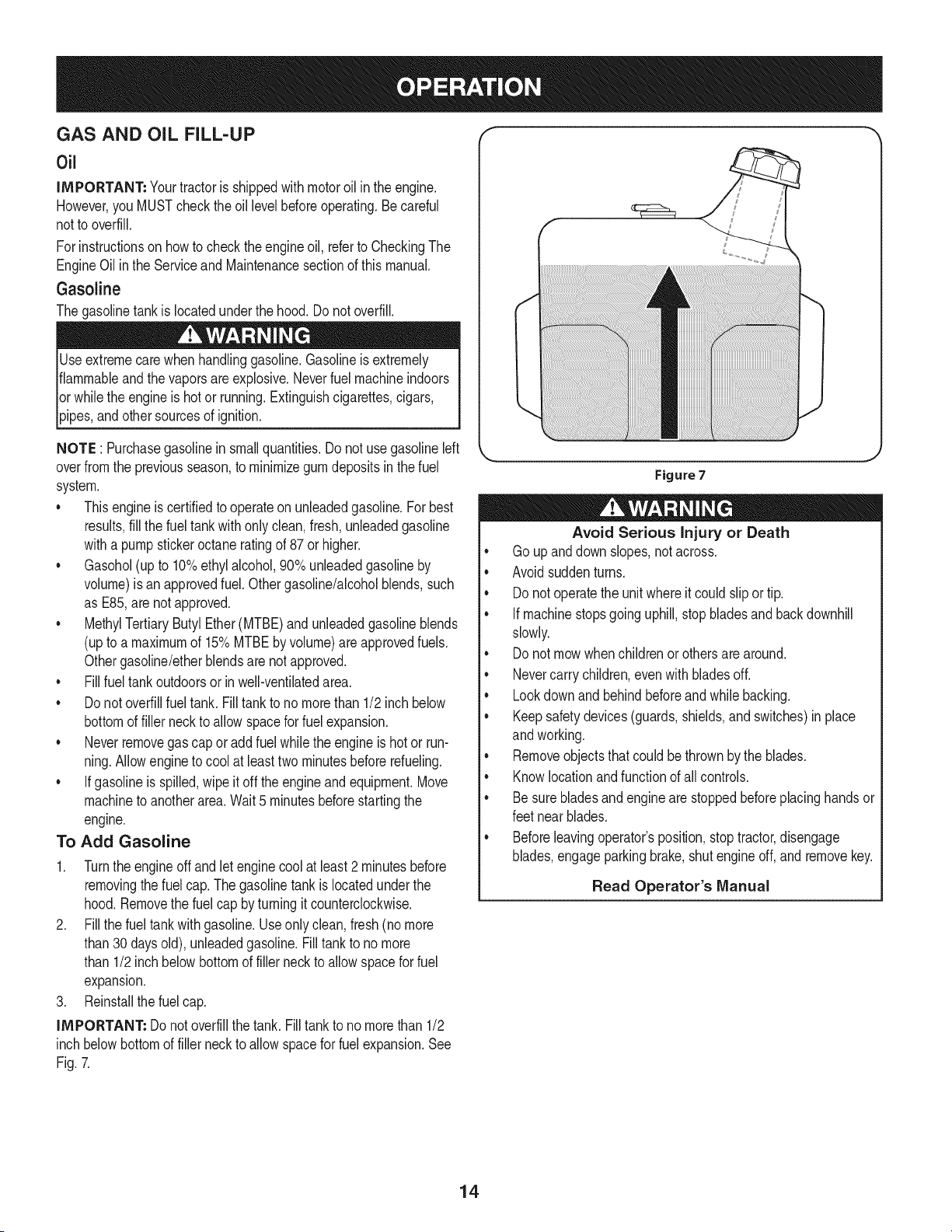
Gasoline
Thegasolinetankis locatedunderthe hood.Do notoverfill.
Useextremecarewhenhandlinggasoline.Gasolineisextremely
flammableandthe vaporsareexplosive.Neverfuel machineindoors
orwhilethe engineishotor running.Extinguishcigarettes,cigars,
_ppes,and othersourcesof gn t on.
NOTE : Purchasegasolineinsmallquantities.Do notuse gasolineleft
overfromthe previousseason,to minimizegumdepositsinthe fuel
system.
• Thisengineiscertifiedto operateon unleadedgasoline.For best
results,fill the fueltankwithonlyclean,fresh,unleadedgasoline
witha pumpstickeroctaneratingof 87or higher.
• Gasohol(up to 10%ethylalcohol,90%unleadedgasolineby
volume)isanapprovedfuel.Othergasoline/alcoholblends,such
as E85,arenot approved.
MethylTertiaryButylEther(MTBE)and unleadedgasolineblends
(upto a maximumof 15%MTBEby volume)are approvedfuels.
Othergasoline/etherblendsare notapproved.
• Fillfuel tankoutdoorsor inwell-ventilatedarea.
• Do notoverfillfuel tank. Filltankto no morethan 1/2inchbelow
bottomof filler neck to allowspacefor fuel expansion.
• Neverremovegas capor add fuel whilethe engineishot or run-
ning.Allowengineto cool at leasttwo minutesbeforerefueling.
• Ifgasolineisspilled,wipe itoff theengineandequipment.Move
machineto anotherarea.Wait5 minutesbeforestartingthe
engine.
To Add Gasoline
1. Turnthe engineoff and let enginecool at least2 minutesbefore
removingthe fuelcap. The gasolinetank islocatedunderthe
hood.Removethe fuel cap byturningitcounterclockwise.
2. Fillthe fuel tankwithgasoline.Useonlyclean,fresh(nomore
than30 daysold), unleadedgasoline.Filltankto nomore
than 1/2inchbelowbottomof filler neck to allowspacefor fuel
expansion.
3. Reinstallthe fuelcap.
iMPORTANT: Do not overfillthetank. Fill tankto nomorethan 1/2
inchbelowbottomof filler neckto allowspacefor fuel expansion.See
Fig.7.
Figure7
Avoid Serious injury or Death
• Go upanddownslopes,notacross.
• Avoidsuddenturns.
• Donot operatethe unitwhereitcould slipor tip.
• If machinestopsgoinguphill,stopbladesand backdownhill
slowly.
• Donot mowwhenchildrenorothersare around.
• Nevercarrychildren,evenwith bladesoff.
• Lookdownand behindbeforeandwhilebacking.
• Keepsafetydevices(guards,shields,and switches)inplace
andworking.
• Removeobjectsthat couldbethrownby the blades.
• Knowlocationandfunctionof all controls.
• Be surebladesandenginearestoppedbeforeplacinghandsor
feetnear blades.
• Beforeleavingoperator'sposition,stoptractor,disengage
blades,engageparkingbrake,shutengineoff, and removekey.
Read Operator's Manual
14
SAFETY iNTERLOCK SYSTEM
Thesafetyinterlocksystemisdesignedfor safeoperationof thetrac-
tor.Ifthis systemshouldever malfunction,do not operatethe tractor.
Immediatelycontact 1-800-4-MY-HOMEto havethe systemserviced.
• Thesafetyinterlocksystempreventsthe enginefromstarting
unlessthe parkingbrakeis engagedandthe PTO(BladeEngage)
leveris in thedisengaged(OFF)position.
• Thesafetyinterlocksystemwill automaticallyshutoffthe engineif
the operatorleavesthe seat beforeengagingthe parkingbrake.
• Thesafetyinterlocksystemwill automaticallyshut offthe engine
ifthe operatorleavesthe tractor'sseat withthe PTO(Blade
Engage)leverengaged,regardlessof whetherthe parkingbrake
is engaged.
• Theenginewill automaticallyshutoff if the PTO(BladeEngage)
leveris movedintothe engaged(ON)positionwiththe shift lever
in Reverse.
IGNITION SWITCH
Theignitionswitchis activatedto startthe engine,insertkey intothe
ignitionswitchandturnclockwiseto the STARTposition.Releasethe
On
Start
off
keyintothe ON positiononce enginehas fired.
Tostopthe engine,turnthe ignitionkey counterclockwiseto the OFF
position.
Neverleavea runningmachineunattended.AlwaysdisengagePTO,
moveshift leverintoneutralposition,setparkingbrake,stopengine
andremovekeyto preventunntendedstartng.
ENGAGING THE PARKING BRAKE
To engage the parking brake:
1. Fullydepressthe brakepedaland holdit downwithyour foot.
2. Movethe speedcontrolleverall the way downandintothe
parkingbrakeposition.
3. Releasethe brakepedalto allow theparkingbraketo engage.
To release the parking brake:
1. Depressthe brakepedalandmovethe speedcontrolleverout of
the parkingbrakepositionandintoa desiredspeed.
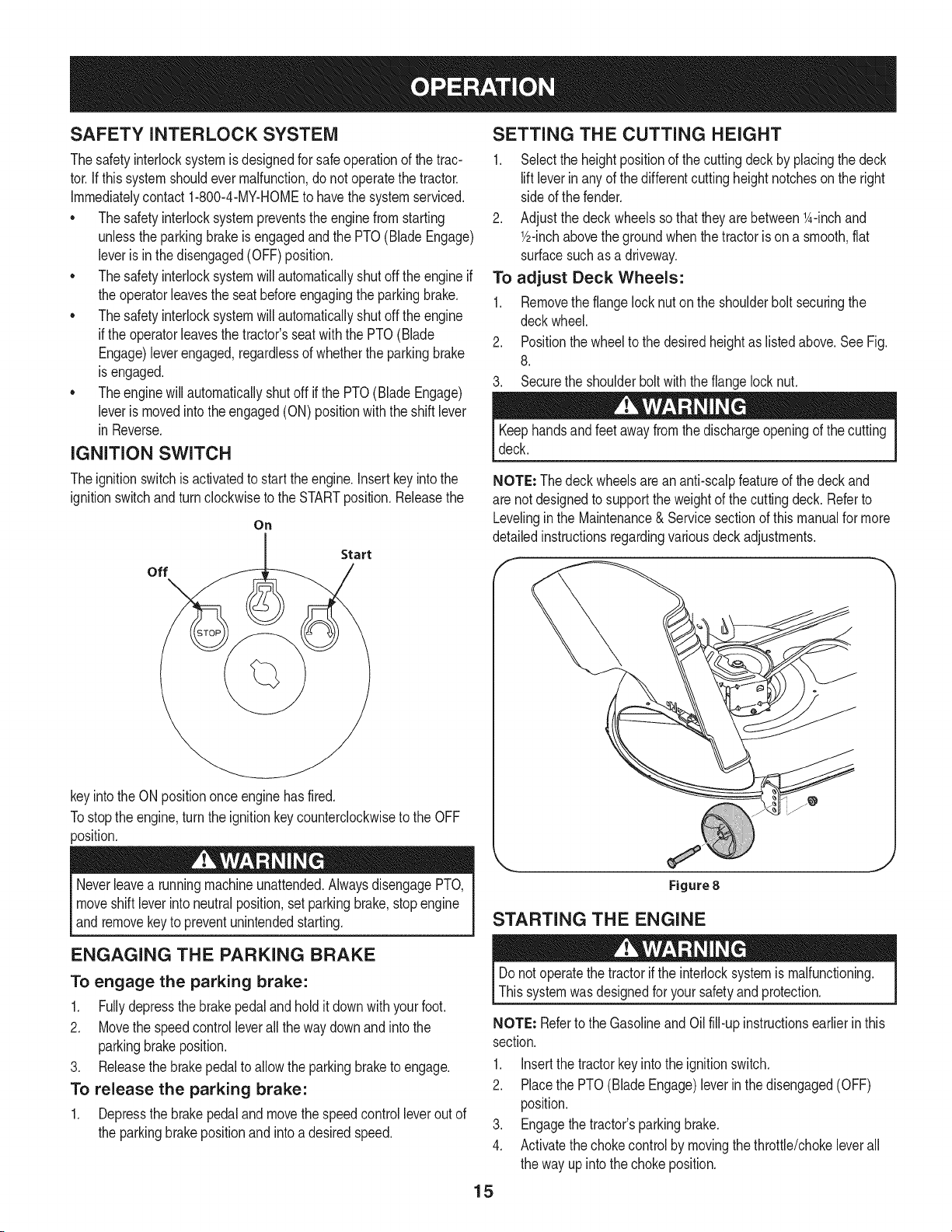
SETTING THE CUTTING HEIGHT
1. Selectthe heightpositionof the cuttingdeckby placingthe deck
liftleverinanyof the differentcuttingheightnotcheson the right
sideof the fender.
2. Adjustthe deck wheelssothattheyarebetween1A-inchand
Y2-inchabovethe groundwhenthe tractoris on a smooth,fiat
surfacesuchas a driveway.
To adjust Deck Wheels:
1. Removethe flangelocknuton the shoulderbolt securingthe
deckwheel.
2. Positionthe wheelto thedesiredheightas listedabove.SeeFig.
8.
3. Securethe shoulderboltwiththe flangelocknut.
Keephandsandfeetawayfromthe dischargeopeningof the cutting
deck.
NOTE: Thedeckwheelsarean anti-scalpfeatureof the deck and
are notdesignedto supportthe weightof the cuttingdeck. Referto
Levelinginthe Maintenance& Servicesectionof thismanualfor more
detailedinstructionsregardingvariousdeckadjustments.
Figure8
STARTING THE ENGINE
Donot operatethe tractorif the interlocksystemis malfunctioning.
Thissystemwas designedfor yoursafetyand protection.
NOTE: Referto the Gasolineand Oilfill-up instructionsearlierin this
section.
1. Insertthe tractorkeyintothe ignitionswitch.
2. Placethe PTO(Blade Engage)leverin thedisengaged(OFF)
position.
3. Engagethe tractor'sparkingbrake.
4. Activatethechokecontrolby movingthethrottle/chokeleverall
the way upintothechoke position.
15
5. Turnthe ignitionkeyclockwiseto the STARTposition.Afterthe
enginestarts,releasethe key.It will returnto the ON (orNormal
Mowing)position.
Do NOTholdthe keyin the STARTpositionfor longerthanten
secondsat a time.Doingso maycausedamageto yourengine's
electricstarter.
6. Afterthe engine starts,deactivatethe chokecontroland placethe
throttlecontrolinthe FASTposition.
NOTE=DoNOTleavethe chokecontrolon whileoperatingthe tractor.
Doingso will resultina "rich" fuel mixtureandcausethe engineto run
poorly.
STOPPING THE ENGINE
If youstrikea foreignobject,stopthe engine,disconnectthe spark
plugwire(s)andgroundagainstthe engine.Thoroughlyinspectthe
machinefor anydamage.Repairthe damagebeforerestartingand
operating
1. Ifthe bladesareengaged,placethe PTO(BladeEngage)leverin
thedisengaged(OFF)position.
2. Turnthe ignitionkeycounterclockwiseto the STOPposition.
3. Removethe keyfromthe ignitionswitchto preventunintended
starting.
DRIVING THE TRACTOR
Avoidsuddenstarts,excessivespeedand suddenstops.
Donot leavethe seatof the tractorwithoutfirst placingthe PTO
(BladeEngage)leverin the disengaged(OFF)position,depressing
the brakepedalandengagingthe parkingbrake.If leavingthe tractor
unattended,also turnthe ignitionkeyoff andremovethe key.
Alwayslook downandbehindbeforeand while backingup to avoida
back-overaccident.
1. Depressthe brakepedalto releasethe parkingbrakeandthen let
the pedal up.
2. Movethethrottleleverintothe FAST(rabbit)position.
3. Placethe shift leverineitherthe FORWARDor REVERSE
position.
IMPORTANT= Do NOTusethe shiftleverto changethe direction
of travelwhenthe tractoris in motion.Alwaysusethe brakepedalto
bringthe tractorto a completestopbeforeshifting.
4. Graduallybeginto applypressureto the drivepedal.Thefurther
downthe pedalis pushed,thefasterthe tractorwilltravel inthe
desireddirectionbasedon the positionof the shift lever.
5. The lawntractoris broughtto a stopby releasingthedrive pedal
andthen depressingthe brakepedal.
Beforeleavingthe operator'spositionfor any reason,disengagethe
blades,placethe shift leverinneutral,engagethe parkingbrake,
shutengineoff and removethe key.
Whenstoppingthetractorfor any reasonwhileon a grasssurface,
always:
1. Placethe shift leverin neutral,
2. Engagethe parkingbrake,
3. Shutengineoff and removethe key.Doingso will minimizethe
possibilityof havingyour lawn"browned"byhot exhaustfrom
yourtractor'srunningengine.
16
DRiViNG ON SLOPES
Referto the SLOPEGAUGEin the SafetyInstructionssectionof the
manualto helpdetermineslopeswhereyou mayoperatethis tractor
safely.
Do notmowon inclineswitha slopein excessof 15degrees(a rise
of approximately2-1/2feetevery 10feet). Thetractorcouldoverturn
andcauseseriousinjury.
• Mowupanddownslopes,NEVERacross.
Exerciseextremecautionwhenchangingdirectionon slopes.
Watchfor holes,ruts,bumps,rocks,or otherhiddenobjects.
Uneventerraincouldoverturnthemachine.Tallgrasscan hide
obstacles.
Avoidturnswhendrivingona slope.Ifa turn mustbemade,turn
downthe slope.Turningup a slopegreatlyincreasesthechance
of a roll over.
Avoidstoppingwhendrivingupa slope.Ifit is necessaryto stop
whiledrivingupa slope,start up smoothlyand carefullyto reduce
the possibilityof flippingthe tractoroverbackward.
ENGAGING THE BLADES
Engagingthe PTO(BladeEngage)transferspowerto the cuttingdeck
orother (separatelyavailable)attachments.Toengagethe blades,
proceedas follows:
1. Movethe throttle/chokecontrol leverto the FAST(rabbit)position.
2. Graspthe PTO(BladeEngage)leverandpivot it all the way
forwardintothe engaged(ON)position.
3. Keepthe throttleleverin the FAST(rabbit)positionforthe most
efficientuseof thecuttingdeckor other(separatelyavailable)
attachments.
NOTE: The enginewillautomaticallyshutoff if the PTOis engaged
withthe shiftleverin positionfor reversetravelwiththe ignitionkey in
the ONposition.
MULCHING
A mulchkit is availableasan attachment.Mulchingis a processof
recirculatinggrassclippingsrepeatedlybeneaththe cuttingdeck.The
ultra-fineclippingsare thenforcedback intothe lawnwherethey act as
a naturalfertilizer.
A mulchkit canbe purchasedthroughthe retaillocationinwhichyou
purchasedthis tractor.For more information, simply contact Sears
at 1-800-4-MY-HOME®.
USING THE DECK LIFT LEVER
Toraisethe cuttingdeck,movethe decklift levertothe left,then place
it in the notchbestsuitedfor yourapplication.Referto SettingThe
CuttingHeightearlierinthis section.
MOWING
Tohelpavoidbladecontactora thrownobjectinjury,keepbystand-
ers,helpers,childrenandpetsat least75feetfromthe machine
while it is in operation.Stopmachineif anyoneentersthe area.
The followinginformationwill be helpfulwhenusingthe cuttingdeck
withyourtractor:
Planyourmowingpatternto avoiddischargeof materialstoward
roads,sidewalks,bystandersandthe like.Also,avoiddischarging
materialagainstawall or obstructionwhichmaycausedischarged
materialto ricochetbacktowardthe operator.
Donot mowat highgroundspeed,especiallyif a mulchkit or
grasscollectoris installed.
• Forbest resultsit is recommendedthat the first twolaps becut
withthe dischargethrowntowardsthe center.Afterthe firsttwo
laps,reversethedirectionto throwthe dischargeto theoutside
for the balanceof cutting.Thiswill givea betterappearanceto the
lawn.
• Donot cutthe grasstoo short. Shortgrassinvitesweedgrowth
andyellowsquicklyin dry weather.
• Mowingshouldalwaysbe donewith the engineat full throttle.
• Underheavierconditionsit maybe necessaryto go backoverthe
cut areaa secondtimeto get a cleancut.
• Do NOTattemptto mowheavybrushandweeds andextremely
tall grass.Yourtractoris designedto mowlawns,NOTclear
brush.
• Keepthe bladessharpand replacethe bladeswhenworn.Refer
to CuttingBladesinthe Servicesectionof thismanualfor proper
bladesharpeninginstructions.
HEADLIGHTS
• The lampsare ONwheneverthe tractor'sengineis running.
• The lampsturn OFFwhenthe ignitionkeyis movedto the STOP
position.
17
MAINTENANCE SCHEDULE
Beforeperforminganytypeof maintenance/service,disengageall
controlsand stoptheengine.Waituntilallmovingpartshavecometo
acompletestop.Disconnectsparkplugwireandgrounditagainstthe
enginetopreventunintendedstarting.Alwayswearsafetyglassesduring
operationor whileperforminganyadjustmentsor repairs.
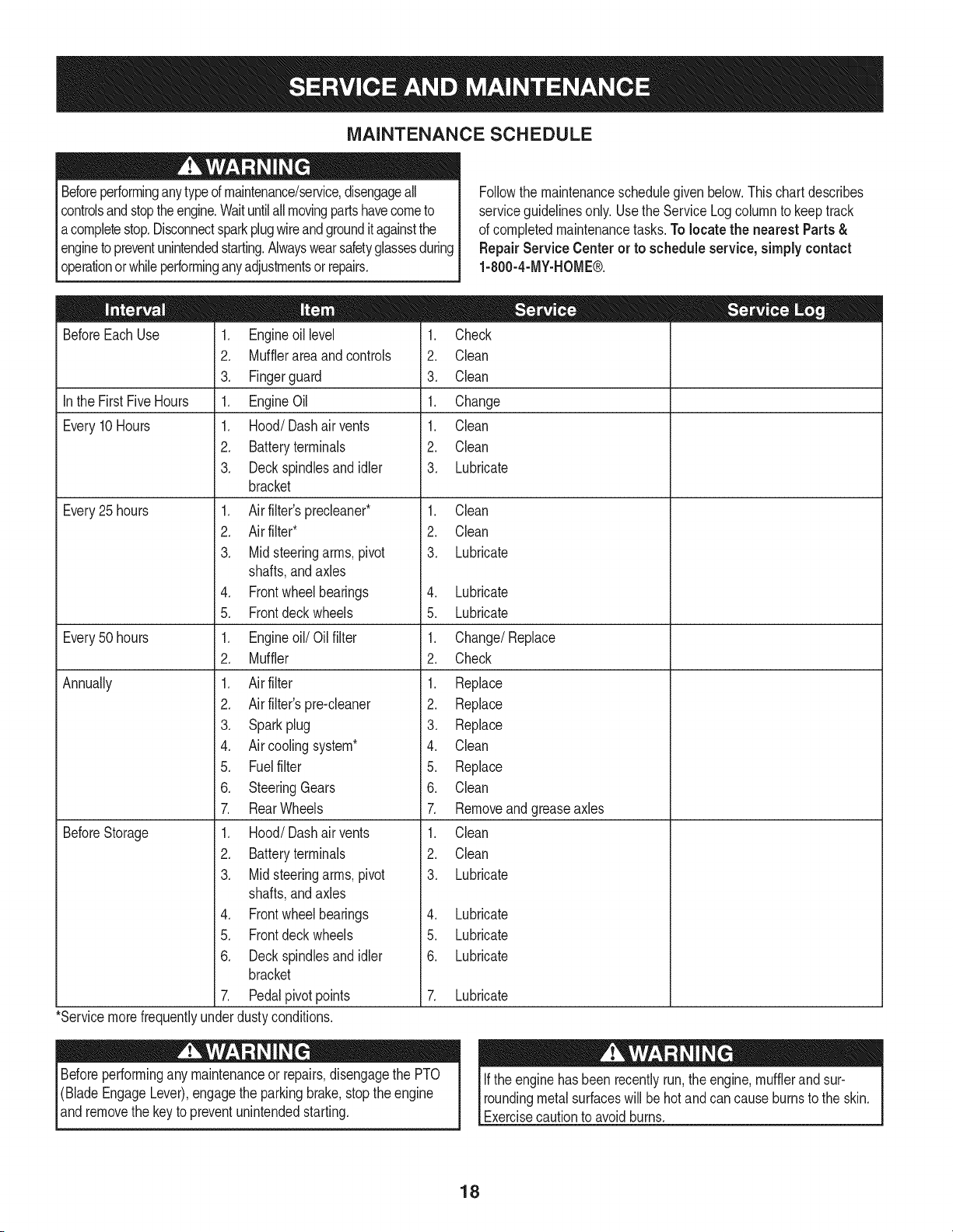
Followthe maintenanceschedulegivenbelow.Thischartdescribes
serviceguidelinesonly.Usethe ServiceLogcolumnto keeptrack
of completedmaintenancetasks.To locate the nearest Parts &
Repair Service Centeror to scheduleservice,simplycontact
1-800-4-MY-HOME®.
BeforeEachUse
In the FirstFiveHours
Every10Hours
Every25 hours
Every50 hours
Annually
BeforeStorage
1. Engineoil level
2. Mufflerareaand controls
3. Fingerguard
1. EngineOil
1. Hood/Dashair vents
2. Batteryterminals
3. Deckspindlesand idler
bracket
1. Air filter'sprecleaner*
2. Air filter*
3. Midsteeringarms,pivot
shafts,andaxles
4. Frontwheelbearings
5. Frontdeckwheels
1. Engineoil/Oil filter
2. Muffler
1. Air filter
2. Air filter'spre-cleaner
3. Sparkplug
4. Air coolingsystem*
5. Fuelfilter
6. SteeringGears
7. RearWheels
1. Hood/Dashair vents
2. Batteryterminals
3. Midsteeringarms,pivot
shafts,andaxles
4. Frontwheelbearings
5. Frontdeckwheels
6. Deckspindlesand idler
bracket
7. Pedalpivotpoints
1. Check
2. Clean
3. Clean
1. Change
1. Clean
2. Clean
3. Lubricate
1. Clean
2. Clean
3. Lubricate
4. Lubricate
5. Lubricate
1. Change/Replace
2. Check
1. Replace
2. Replace
3. Replace
4. Clean
5. Replace
6. Clean
7. Removeandgreaseaxles
1. Clean
2. Clean
3. Lubricate
4. Lubricate
5. Lubricate
6. Lubricate
7. Lubricate
*Servicemorefrequentlyunderdustyconditions.
Beforeperformingany maintenanceor repairs,disengagethe PTO
(BladeEngageLever),engagethe parkingbrake,stopthe engine
and removethe keyto preventunintendedstarting.
Ifthe enginehasbeen recentlyrun,the engine,mufflerand sur-
roundingmetalsurfaceswill behotand cancause burnsto the skin.
Exercisecautionto avoidburns.
18
ENGINE MAINTENANCE
Checking the Engine Oil
Onlyuse highqualitydetergentoil ratedwithAPIserviceclassification
SF,SG,SH,or SJ, Selectthe oil's SAEviscositygradeaccordingto
the expectedoperatingtemperature.Followthe chartbelow.
Althoughmulti-viscosityoils (5W20,10W30,etc.)improvestarting
in coldweather,theywill resultinincreasedoil consumptionwhen
usedabove32°E Checkyour engineoillevelmorefrequentlyto avoid
possibleenginedamagefromrunninglowonoil.
('_older _ 32°F _War me'_r
Oil Viscosity Chart
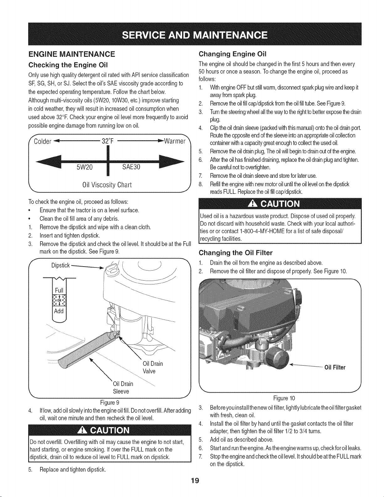
Tocheckthe engineoil, proceedas follows:
• Ensurethat the tractoris ona levelsurface.
• Cleantheoil fill areaof anydebris.
1. Removethedipstickandwipe withaclean cloth.
2. Insertandtightendipstick.
3. Removethe dipstickandchecktheoil level.It shouldbeat the Full
markon thedipstick.SeeFigure9.
f
Dipstick-_
OilDrain
Valve
Oil Drain
Sleeve
Figure9
Iflow,addoilslowlyintotheengineoilfill. Donotoverfill.Afteradding
oil, waitone minuteandthen recheckthe oil level.
Donotoverfill.Overfillingwithoil maycausethe engineto not start,
hardstarting,or enginesmoking.If overthe FULLmarkon the
dipstick,drainoil to reduceoil levelto FULLmarkon dipstick.
5. Replaceandtightendipstick.
Changing Engine Oil
The engineoil shouldbe changedinthe first 5 hoursand thenevery
50 hoursoronce a season.Tochangethe engineoil, proceedas
follows:
1. WithengineOFFbutstillwarm,disconnectsparkplugwireandkeepit
awayfromsparkplug.
2. Removetheoilfillcap/dipstickfromtheoilfilltube.SeeFigure9.
3. Turnthesteeringwheelallthewaytothe righttobetterexposethedrain
plug.
4. Cliptheoildrainsleeve(packedwiththismanual)ontotheoildrainport.
Routetheoppositeendofthesleeveintoanappropriateoilcollection
containerwithacapacitygreatenoughtocollecttheusedoil.
5. Removetheoildrainplug,Theoil willbegintodrainoutoftheengine.
6. Aftertheoilhasfinisheddraining,replacetheoildrainplugandtighten.
Becarefulnottoovertighten.
7. Removetheoildrainsleeveandstoreforlateruse.
8. Refilltheenginewithnewmotoroiluntiltheoillevelonthedipstick
readsFULL.Replacetheoilfillcap/dipstick.
Usedoil is a hazardouswasteproduct.Disposeof usedoil properly.
Do notdiscardwithhouseholdwaste.Checkwith your localauthori-
ties oror contact1-800-4-MY-HOMEfor alist of safedisposal/
recyclingfacilities.
Changing the Oil Filter
1. Drainthe oil fromthe engineas describedabove.
2. Removethe oil filterand disposeof properly.See Figure10.
Figure10
3. Beforeyouinstallthenewoilfilter,lightlylubricatetheoilfiltergasket
withfresh,cleanoil.
4. Installthe oil filter byhanduntilthe gasketcontactstheoil filter
adapter,then tightenthe oilfilter 1/2to 3/4 turns.
5. Addoil as describedabove.
6. Startand runtheengine.Astheenginewarrnsup,checkforoilleaks.
7. Stoptheengineandchecktheoillevel.ItshouldbeattheFULLmark
on the dipstick.
19
Fuel Filter Air Cleaner
Gasolineand itsvaporsareextremelyflammableand explosive.Fire
orexplosioncan causesevereburnsor death.
• Keepgasolineawayfrom sparks,openflames,pilotlights,heat,
andotherignitionsources.
• Checkfuel lines,tank,cap, andfittingsfrequentlyforcracksor
leaks.Replaceif necessary.
• Beforereplacingthe fuelfilter,drainthe fueltankas perthe
instructionsbelow.
• Do notdrainfuel whenthe engineishot. Allowthe engine
adequatetimeto cool. Drainfuel intoan approvedcontainer
outdoors,awayfromopenflame.
• Drainanylargevolumeof fuelfrom the tank by disconnectingthe
fuel linefromthe in-linefuelfilternear theengine.
• Removethe fuel line fromthe In-lineside (sidetowardsthe fuel
tank)of thefuel filter.
• Replacementpartsmustbethe sameand installedin the same
positionas theoriginalparts.
• Iffuel spills,waituntil itevaporatesbeforestartingengine.
• Beforereplacingthe fuelfilter,drainthe fueltank. Otherwisefuel
can leakout andcausea fireor explosion.
To Drainthe fuel:
1. Locatethefuelfilter,whichis routedonthe leftsideofthe engine
betweenthe fueltankand the carburetor,and maybeattachedto
theenginewitha tie strap.Cutthetie strap,ifpresent,then pinch
thein-lineclamponthefuelfilterwitha pairof pliers,slidethe
clampupthefuelline.Pullthe fuellinefreefromthefilterandplace
theopenendof the lineintoanapprovedcontainerto drainthefuel.
To changethe fuel filter:
1. Useplierstosqueezethetabsontheotherclamp(theout-linesideof
thefuel filter),then slidethe clampawayfromthe fuelfilter.Twist
andpull the fuellineoff of the fuel filter.See Figure11.
Clamp
Fuel
Line
Tab
Figure11
Iffilters,or coversare notinstalledcorrectlyseriousinjuryor death
could resultfrom backfire.Do notattemptto startthe enginewith
themremoved.
Donot use pressurizedair or solventsto cleanthe air cleaner
cartridge.
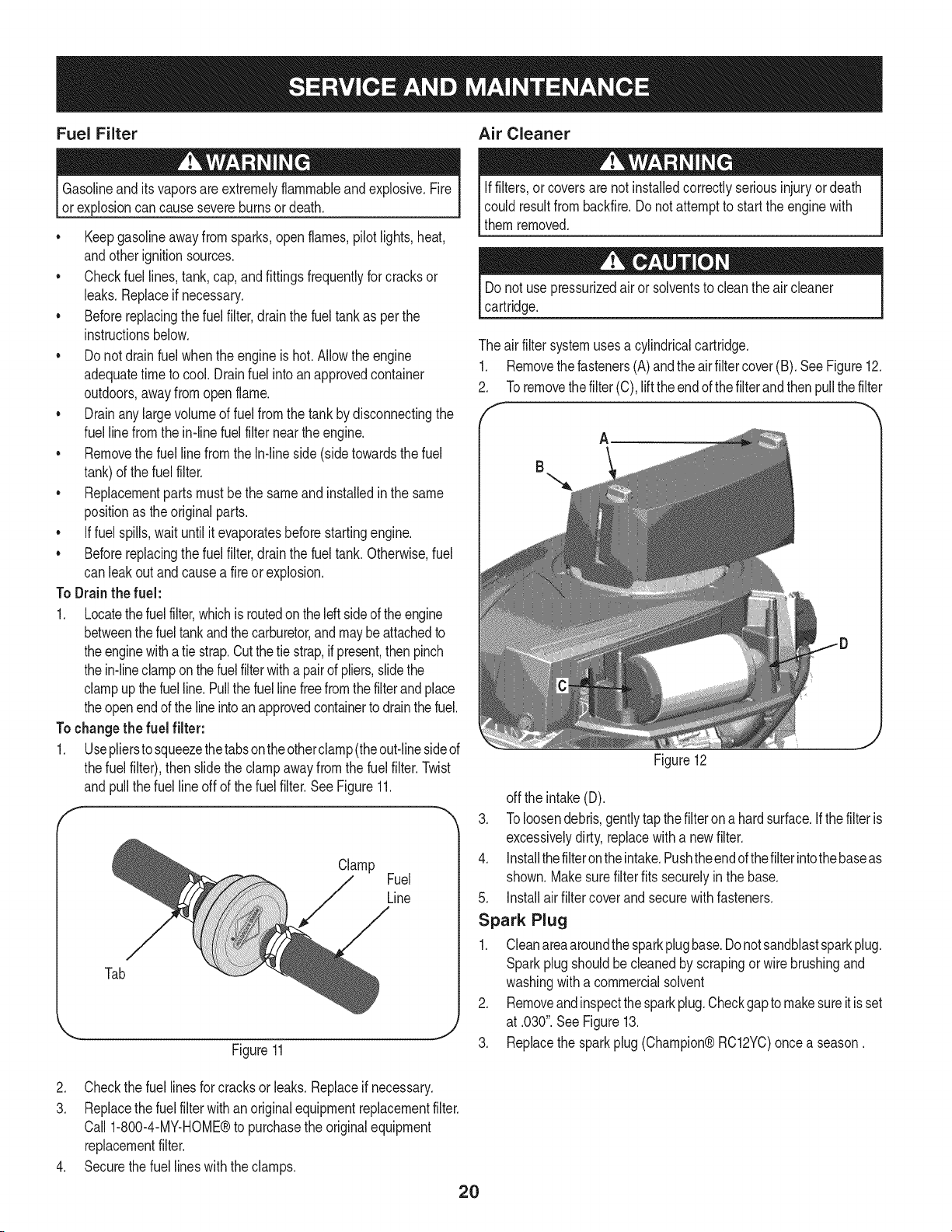
The airfiltersystemuses a cylindricalcartridge.
1. Removethefasteners(A)andtheair filtercover(B). SeeFigure12.
2. Toremovethefilter (C),lifttheendofthe filterandthen pullthefilter
f --
A
B
Figure12
off the intake(D).
3. Toloosendebris,gentlytapthefilteronahardsurface.Ifthe filteris
excessivelydirty,replacewith a newfilter.
4. Installthefilterontheintake.Pushtheendofthefilterintothebaseas
shown.Makesurefilterfits securelyin thebase.
5. Installairfilter coverand securewithfasteners.
Spark Plug
1. Cleanareaaroundthesparkplugbase.Donotsandblastsparkplug.
Sparkplugshouldbe cleanedby scrapingor wirebrushingand
washingwitha commercialsolvent
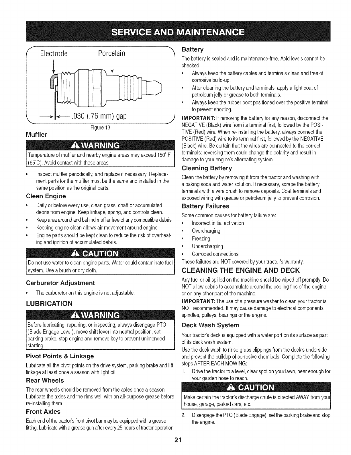
2. Removeandinspectthesparkplug.Checkgapto makesureitis set
at .030".SeeFigure13.
3. Replacethe sparkplug(Champion®RC12YC)oncea season.
2. Checkthe fuel linesfor cracksor leaks.Replaceif necessary.
3. Replacethe fuelfilterwithanoriginalequipmentreplacementfilter.
Call 1-800-4-MY-HOME®to purchasethe originalequipment
replacementfilter.
4. Securethe fuel lineswith the clamps.
20
f
Electrode Porcelain
J
Temperatureof mufflerand nearbyengineareasmayexceed150° F
(65°0).Avoidcontactwith theseareas.
• inspectmufflerperiodically,and replaceif necessary.Replace-
mentpartsfor the mufflermustbethe sameand installedin the
samepositionas the originalparts.
Clean Engine
• Dailyor beforeeveryuse,cleangrass,chaff oraccumulated
debrisfromengine.Keeplinkage,spring,andcontrolsclean.
• Keepareaaroundand behindmufflerfreeofanycombustibledebris.
• Keepingenginecleanallowsair movementaroundengine.
• Enginepartsshouldbe keptcleanto reducethe riskof overheat-
ingandignitionof accumulateddebris.
Do notuse waterto cleanengineparts.Watercouldcontaminatefuel
system.Usea brushor dry cloth.
Carburetor Adjustment
• Thecarburetoron thisengineis not adjustable.
LUBRICATION
Beforelubricating,repairing,or inspecting,alwaysdisengagePTO
(BladeEngageLever),moveshift leverinto neutralposition,set
parkingbrake,stopengineand removekeyto preventunintended
starting.
Pivot Points & Linkage
Lubricateall the pivotpointson thedrive system,parkingbrakeand lift
linkageat leastoncea seasonwithlightoil.
Rear Wheels
Battery
The batteryis sealedandis maintenance-free.Acidlevelscannotbe
checked.
• Alwayskeepthe batterycablesandterminalscleanandfree of
corrosivebuild-up.
• Aftercleaningthe batteryandterminals,applya lightcoatof
petroleumjelly orgreaseto bothterminals.
• Alwayskeepthe rubberbootpositionedoverthe positiveterminal
to preventshorting.
IMPORTANT: if removingthe batteryfor any reason,disconnectthe
NEGATIVE(Black)wirefrom itsterminalfirst, followedby the POSI-
TIVE(Red)wire.When re-installingthe battery,alwaysconnectthe
POSITIVE(Red)wire to its terminalfirst, followedbythe NEGATIVE
(Black)wire.Becertainthatthe wiresareconnectedto the correct
terminals;reversingthemcouldchangethe polarityandresultin
damageto yourengine'salternatingsystem.
Cleaning Battery
Cleanthe batteryby removingit fromthe tractorandwashingwith
a bakingsodaandwatersolution.If necessary,scrapethe battery
terminalswitha wirebrushto removedeposits.Coatterminalsand
exposedwiringwithgreaseor petroleumjelly to preventcorrosion.
Battery Failures
Somecommoncausesfor batteryfailureare:
• incorrectinitialactivation
• Overcharging
• Freezing
• Undercharging
• Corrodedconnections
Thesefailuresare NOTcoveredbyyourtractor'swarranty.
CLEANING THE ENGINE AND DECK
Any fuelor oil spilledon the machineshouldbewipedoff promptly.Do
NOTallowdebristo accumulatearoundthe coolingfinsof the engine
or onany otherpartof the machine.
IMPORTANT: Theuse of a pressurewasherto cleanyourtractoris
NOTrecommended,it may causedamageto electricalcomponents,
spindles,pulleys,bearingsor the engine.
Deck Wash System
Yourtractor'sdeckis equippedwitha water porton itssurfaceas part
of itsdeck washsystem.
Usethe deck washto rinsegrassclippingsfromthe deck'sunderside
and preventthe buildupof corrosivechemicals.Completethe following
stepsAFTEREACHMOWING:
1. Drivethe tractorto a level,clearspotonyourlawn,near enoughfor
yourgardenhoseto reach.
The rearwheelsshouldbe removedfrom the axles oncea season.
Lubricatethe axlesandthe rimswell with anall-purposegreasebefore
re-installingthem.
Front Axles
Eachendof thetractor'sfrontpivotbarmaybeequippedwitha grease
fitting.Lubricatewitha greasegunafterevery25 hoursoftractoroperation.
Makecertainthe tractor'sdischargechuteis directedAWAYfromyoul
house,garage,parkedcars,etc.
2. DisengagethePTO(BladeEngage),setthe parkingbrakeandstop
the engine.
21
3. Threadthe hosecoupler(packagedwith yourtractor'sOperator's
Manual)ontothe endof your gardenhose.
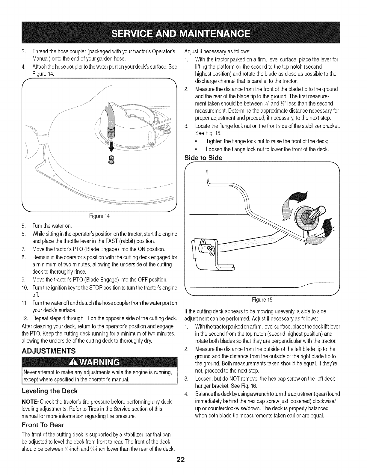
4. Attachthehosecouplertothewaterporton yourdeck'ssurface.See
Figure14.
J
j,
/
f
J _; .......... ........
8
Figure14
5. Turnthe wateron.
6. Whilesittingintheoperator'spositiononthe tractor,starttheengine
andplacethe throttleleverinthe FAST(rabbit)position.
7. Movethe tractor'sPTO(BladeEngage)intothe ON position.
8. Remainin theoperator'spositionwiththecuttingdeck engagedfor
a minimumof two minutes,allowingthe undersideof the cutting
deckto thoroughlyrinse.
9. Movethe tractor'sPTO(BladeEngage)intothe OFFposition.
10. Turntheignitionkeytothe STOPpositionto turnthetractor'sengine
off.
11. Turnthewateroffanddetachthehosecouplerfromthewaterporton
yourdeck'ssurface.
12. Repeatsteps4 through11on the oppositesideof the cuttingdeck.
Aftercleaningyourdeck, returnto the operator'spositionand engage
the PTO.Keepthe cuttingdeckrunningfor a minimumof twominutes,
allowingthe undersideof thecuttingdeckto thoroughlydry.
ADJUSTMENTS
Neverattemptto makeanyadjustmentswhilethe engineis running,
exceptwherespecifiedin the operator'smanual.
Leveling the Deck
NOTE: Checkthe tractor'stire pressurebeforeperforminganydeck
levelingadjustments.Referto Tiresinthe Servicesectionof this
manualfor moreinformationregardingtire pressure.
Front To Rear
Thefrontof the cuttingdeckissupportedby a stabilizerbarthatcan
beadjustedto levelthe deckfromfront to rear.Thefront of the deck
shouldbebetween_A-inchand 3A-inchlowerthan the rear of thedeck.
Adjustif necessaryas follows:
1. Withthe tractorparkedona firm, levelsurface,placethe leverfor
liftingthe platformon the secondto the top notch(second
highestposition)and rotatethe bladeas closeas possibleto the
dischargechannelthatis parallelto the tractor.
2. Measurethedistancefromthe frontof the bladetip to the ground
andthe rearof the bladetip to theground.Thefirst measure-
menttakenshouldbe between_A"and3A"less thanthe second
measurement.Determinethe approximatedistancenecessaryfor
properadjustmentand proceed,if necessary,to the nextstep.
3. Locatethe flangelocknuton thefront sideof thestabilizerbracket.
See Fig.15.
• Tightenthe flangelocknut to raisethe frontof the deck;
• Loosentheflangelock nutto lowerthe frontof thedeck.
Side to Side
Figure15
f__
J
Ifthe cuttingdeckappearsto be mowingunevenly,a sideto side
adjustmentcan beperformed.Adjustif necessaryas follows:
1. Withthetractorparkedonafirm,levelsurface,placethedeckliftlever
in the secondfromthetop notch(secondhighestposition)and
rotatebothbladessothattheyare perpendicularwith the tractor.
2. Measurethedistancefromthe outsideof the left bladetip to the
groundandthe distancefrom the outsideof the rightblade tip to
the ground.Bothmeasurementstakenshouldbe equal.Ifthey're
not, proceedto the nextstep.
3. Loosen,but do NOTremove,the hexcap screwon the leftdeck
hangerbracket.SeeFig. 16.
4. Balancethedeckbyusingawrenchtoturntheadjustmentgear(found
immediatelybehindthe hexcap screwjust loosened)clockwise/
up orcounterclockwise/down.Thedeck is properlybalanced
when bothbladetip measurementstakenearlierareequal.
22
He× Cap Screw
'_._. j
Figure16
5. Retightenthehex capscrewonthe leftdeck hangerbracketwhen
properadjustmentis achieved.
Seat Adjustment
Referto the Assemblysectionof this manualfor seatadjustment
instructions.
Parking Brake Adjustment
Neverattemptto adjustthe brakeswhiletheengineis running.Always
disengagePTO(bladeengage)lever,moveshiftleverintoneutral
position,stopengineandremovekeyto preventunintendedstarting.
If thetractordoes notcometo acompletestopwhenthe brakepedal
is completelydepressed,or if the tractor'srearwheelscan rollwiththe
parkingbrakeapplied,the brakeis in needof adjustment.Contactthe
nearest Sears Service Center to haveyourbrakesproperlyadjusted.
Tolocatethe nearest Parts& Repair ServiceCenteror to schedule
service,contact 1-800-4-MY-HOME®.
CUTTING DECK REMOVAL
To remove the cutting deck, proceed as follows:
1. Placethe PTO(Blade Engage)leverin the disengaged(OFF)
positionand engagethe parkingbrake.
2. Lowerthe deck by movingthe deck lift lever intothe bottom
notchon the rightfender.
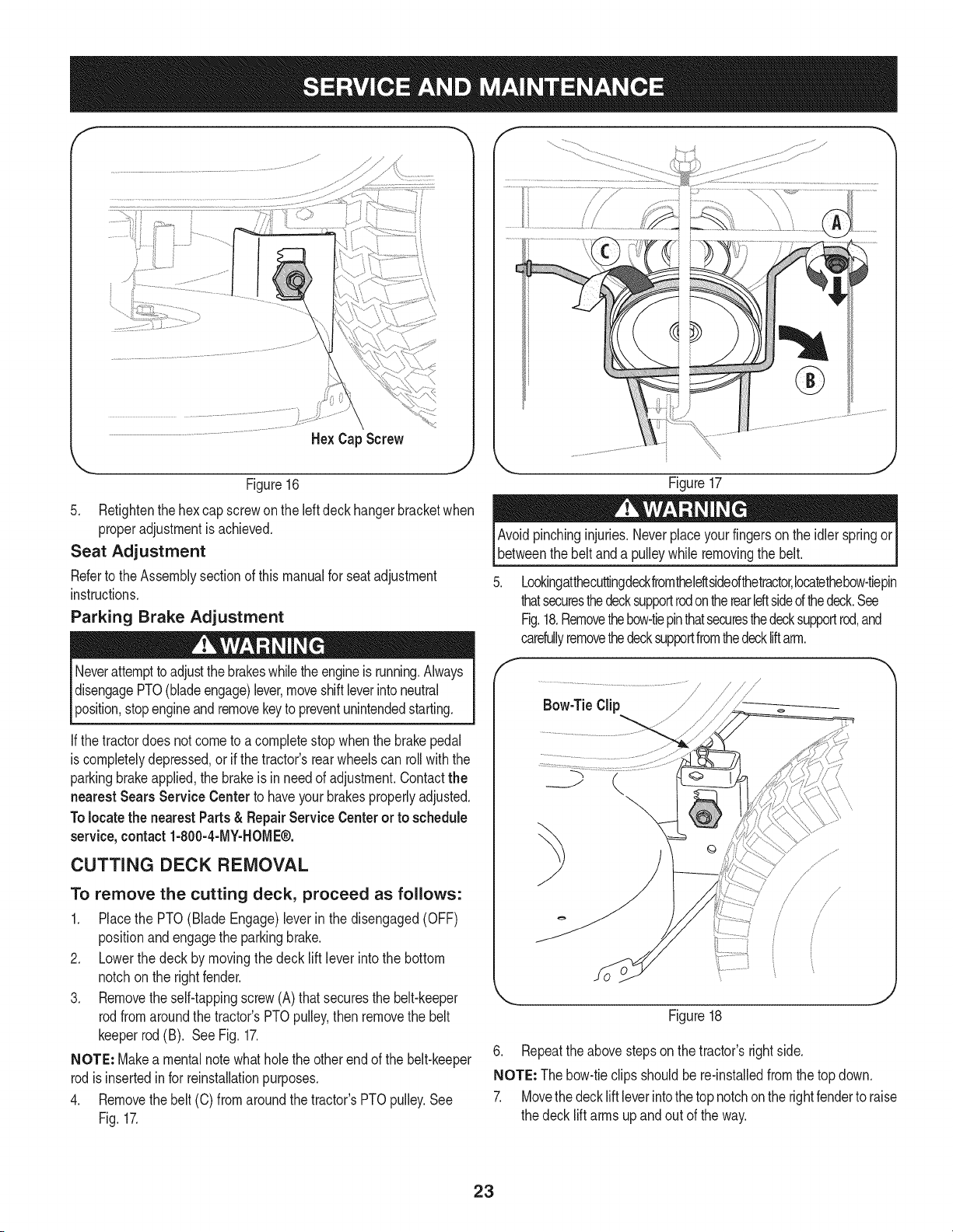
3. Removetheself-tappingscrew(A) that securesthe belt-keeper
rodfromaroundthe tractor'sPTOpulley,thenremovethe belt
keeperrod(B). SeeFig. 17.
NOTE: Makea mentalnotewhatholethe otherendof the belt-keeper
rodisinsertedin for reinstallationpurposes.
4. Removethebelt (C) from aroundthetractor'sPTOpulley.See
Fig.17.
Figure17
Avoidpinchinginjuries.Neverplaceyourfingerson the idlerspringor
betweenthe beltand a pulleywhileremovingthe belt.
Lookingatthecuttingdeckfromtheleftsidedthetractor,Iocatethebow-tiepin
thatsecuresthedecksupportrodontherearIdt sided thedeck.See
Fig.18.Removethebow-tiepinthatsecuresthedecksupportrod,and
carefullyremovethedecksupportfromthedeckliftarm.
Figure18
6. Repeatthe abovestepson the tractor'srightside.
NOTE: Thebow-tieclipsshouldbe re-installedfrom the topdown.
7. Movethedeck liftleverintothe topnotchonthe rightfenderto raise
the deck lift armsupandout of theway.
23
.
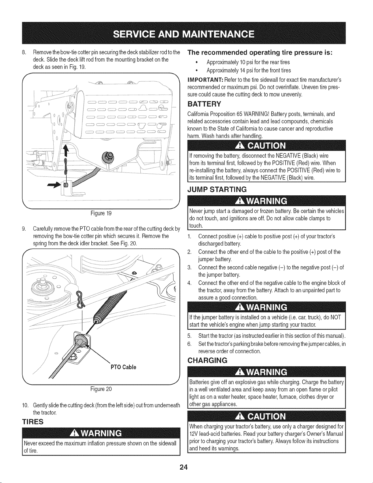
Removethebow-tiecotterpinsecuringthedeck stabilizerrodto the
deck.Slidethedeck lift rodfromthe mountingbracketon the
deckas seenin Fig.19.
..........._'_¢& _ .......................................
Figure19
.
f
Carefullyremovethe PTOcablefromthe rearof thecuttingdeck by
removingthe bow-tiecotter pin whichsecuresit. Removethe
springfromthe deckidlerbracket.SeeFig.20.
PTOCable
Figure20
10. Gentlyslidethecuttingdeck(fromtheleftside)outfrom underneath
thetractor.
TIRES
Neverexceedthe maximuminflationpressureshownonthe sidewall
of tire.
The recommended operating tire pressure is:
• Approximately10psi for the reartires
• Approximately14psi for the fronttires
IMPORTANT: Referto the tire sidewallfor exacttire manufacturer's
recommendedor maximumpsi.Donot overinflate.Uneventire pres-
surecould causethe cuttingdeckto mowunevenly.
BATTERY
CaliforniaProposition65 WARNING!Batteryposts,terminals,and
relatedaccessoriescontainleadandleadcompounds,chemicals
knownto the Stateof Californiato causecancer andreproductive
harm.Washhandsafter handling.
If removingthe battery,disconnectthe NEGATIVE(Black)wire
fromits terminalfirst,followedbythe POSITIVE(Red) wire.When
re-installingthe battery,alwaysconnectthe POSITIVE(Red)wire to
I ts termna f rst,fo owedby the NEGATVE (B ack)w re.
JUMP STARTING
Neverjump starta damagedor frozenbattery.Becertain thevehicles
do not touch,and ignitionsareoff. Do notallowcable clampsto
touch.
1. Connectpositive(+)cableto positivepost (+)of yourtractor's
dischargedbattery.
2. Connecttheotherendof thecableto the positive(+)post of the
jumperbattery.
3. Connectthesecondcable negative(-) to the negativepost(-) of
the jumperbattery.
4. Connecttheotherendof thenegativecableto the engineblockof
the tractor,awayfromthe battery.Attachto anunpaintedpartto
assurea goodconnection.
Ifthejumper batteryis installedona vehicle(i.e.car,truck),do NOT
startthe vehicle'senginewhenjump startingyourtractor.
5. Startthetractor(asinstructedearlierin thissectionofthismanual).
6. Setthetractor'sparkingbrakebeforeremovingthejumpercables,in
reverseorderof connection.
CHARGING
give offan explosivegas whilecharging.Chargethe batteryI
Batteries
ina wellventilatedareaand keepawayfroman openflame or pilot
ght as ona waterheater,spaceheater,furnace,c othesdryeror |
othergas appliances.
J
Whenchargingyourtractor'sbattery,useonlya chargerdesignedfor I
12Vlead-acidbatteries.Readyourbatterychargers Owners Manual
priorto chargingyourtractors battery.Alwaysfollowits instructions I
land heed ts warnngs. j
24
If yourtractorhasnot beenputinto usefor an extendedperiodof time,
chargethe batteryas follows:
1. Setyour batterychargerto delivera max of 10amperes.
If yourbatterychargeris automatic,chargethe batteryuntilthe
chargerindicatesthat chargingis complete.Ifthe chargeris not
automatic,chargefor nofewerthaneight hours.
FUSE
One20 AMPfuseis installedin yourtractor'swiringharnessto protect
the tractor'selectricalsystemfrom damagecausedbyexcessive
amperage.
If theelectricalsystemdoesnot function,or yourtractor'senginewill
not crank,first checkto be certainthat the fuse hasnot blown.It can
befoundat the rearof the unit,underneaththefenderlocatedby the
battery.
Alwaysusea fusewiththe sameamperagecapacityfor replacement.
CUTTING BLADES
Shutthe engineoff and removeignitionkey beforeremovingthe
cuttingblade(s)for sharpeningor replacement.Protectyourhands
by usingheavygloveswhengraspingthe blade.
Periodicallyinspectthe bladeand/or spindlefor cracksordamage,
especiallyafter you'vestrucka foreignobject. Donot operatethe
machineuntil damagedcomponentsare replaced.
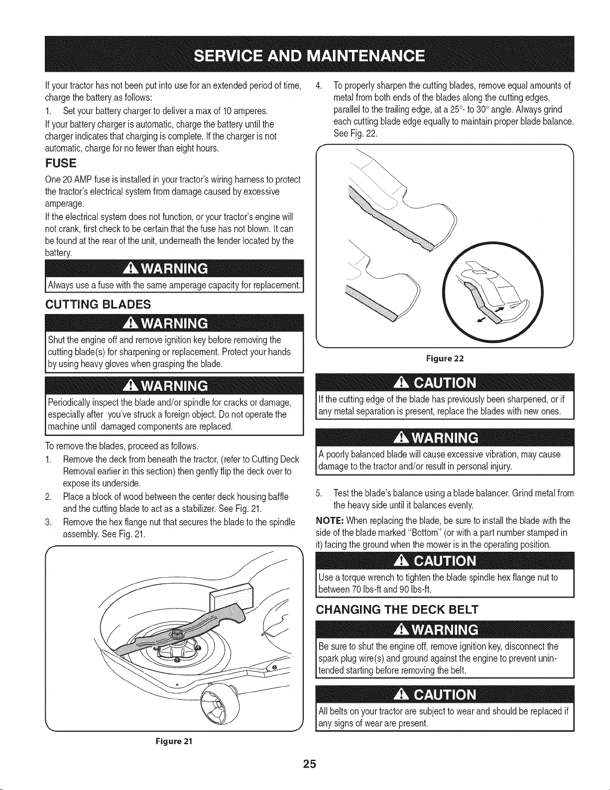
To properlysharpenthe cuttingblades,removeequalamountsof
metalfrombothendsof the bladesalongthe cuttingedges,
parallelto the trailingedge,at a 250.to 300angle.Alwaysgrind
eachcutting bladeedgeequallyto maintainproperbladebalance.
SeeFig.22.
Figure 22
Ifthe cuttingedgeof the bladehas previouslybeen sharpened,or if
any metalseparationis present,replacethe bladeswith newones.
Toremovethe blades,proceedas follows.
1. Removethedeckfrombeneaththe tractor,(referto CuttingDeck
Removalearlierinthis section)thengently flip thedeck overto
exposeitsunderside.
2. Placea blockof woodbetweenthe centerdeckhousingbaffle
andthe cuttingbladeto actas a stabilizer.See Fig.21.
3. Removethehex flangenutthat securesthe blade to the spindle
assembly.SeeFig.21.
A poorlybalancedbladewill causeexcessivevibration,maycause
damageto the tractorand/or resultin personalinjury.
5. Testthe blade'sbalanceusinga bladebalancer.Grindmetalfrom
the heavysideuntil it balancesevenly.
NOTE: Whenreplacingtheblade,be sureto installthe blade withthe
sideof the blademarked"Bottom" (orwith a part numberstampedin
it)facingthe groundwhenthe moweris inthe operatingposition.
Figure 21
Usea torquewrenchto tightenthe bladespindlehexflangenut to
between70Ibs-ftand 90 Ibs-ft.
CHANGING THE DECK BELT
Besureto shutthe engineoff, removeignitionkey,disconnectthe
Isparkplugwire(s)andgroundagainstthe engineto preventunin-
ltended startingbeforeremovingthe belt.
All beltsonyourtractoraresubjectto wearandshouldbereplacedif
any signsof wearare present.
25
iMPORTANT: The V-beltfoundon yourtractorisspeciallydesigned
to engageanddisengagesafely.A substitute(non-OEM)V-beltcan
bedangerousby notdisengagingcompletely.Fora properworking
machine,useidenticalequipmentbeltsas listedinthe partspagesof
thisOperator'sManual.
Tochangeor replacethe deckbelt onyourtractor,proceedas follows:
1. Removethe deckas instructedearlierinthis section.
2. Removethe beltcoversfromthe spindlepulleysby removingthe
hexscrewsthatfastenthecoversto the deck.SeeFig.23.
3. Loosenthe hex nutson the deckidlerpulleysto get the beltoff
(andon) the pulleysandaroundthe beltguards.Afterloosening
thedeck idlerpulleys,rotatethe beltguideoutof thewayon the
rightidlerpulleyto remove(and reinstall)the belt.
4. Carefullyremovethe deck beltfromaroundthe twospindle
pulleysandthetwo deck idlerpulleys.SeeFig.23.
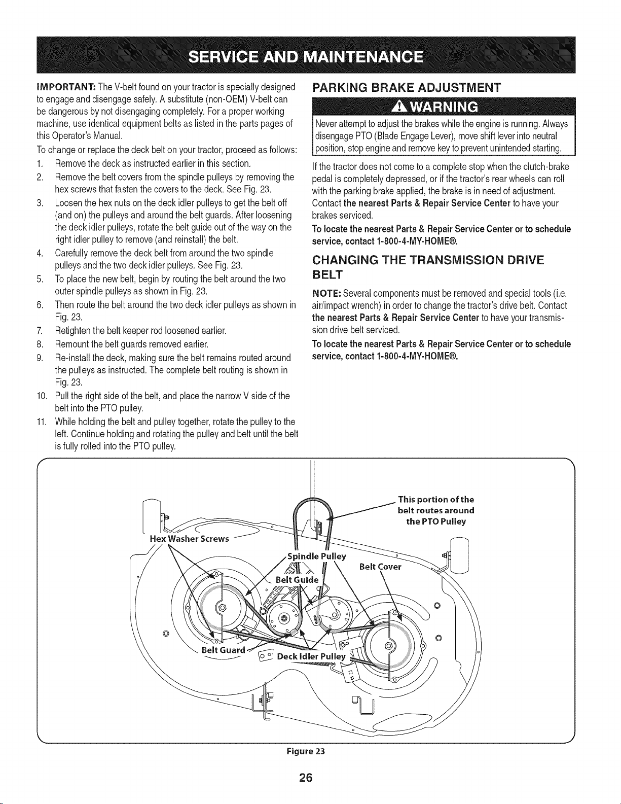
5. Toplacethe newbelt,begin by routingthe belt aroundthe two
outerspindlepulleysas shownin Fig.23.
6. Thenroutethe beltaroundthe twodeckidlerpulleysas shownin
Fig.23.
7. Retightenthe belt keeperrodloosenedearlier.
8. Remountthebelt guardsremovedearlier.
9. Re-installthedeck, makingsurethe belt remainsroutedaround
the pulleysas instructed.Thecompletebelt routingisshownin
Fig.23.
10. Pullthe rightside ofthe belt,and placethe narrowVside of the
belt intothe PTOpulley.
11. Whileholdingthe beltandpulleytogether,rotatethepulleyto the
left. Continueholdingandrotatingthe pulleyand beltuntilthe belt
isfullyrolledintothe PTOpulley.
PARKING BRAKE ADJUSTMENT
Neverattemptto adjustthe brakeswhiletheengineis running.Always
disengagePTO(BladeEngageLever),moveshiftleverintoneutral
position,stopengineandremovekeyto preventunintendedstarting.
Ifthe tractordoesnot cometo a completestop whenthe clutch-brake
pedaliscompletelydepressed,or ifthe tractor'srearwheelscan roll
withthe parkingbrakeapplied,the brakeis inneed of adjustment.
Contactthe nearest Parts & RepairService Centerto haveyour
brakesserviced.
To locatethe nearestParts& RepairService Centeror to schedule
service,contact1-800-4-MY-HOME®.
CHANGING THE TRANSMiSSiON DRIVE
BELT
NOTE: Severalcomponentsmust beremovedandspecialtools (i.e.
air/impactwrench)inorder to changethetractor'sdrivebelt. Contact
the nearest Parts & Repair Service Center to haveyourtransmis-
sion drivebelt serviced.
To locatethe nearestParts & RepairService Centeror to schedule
service, contact 1-800-4-MY-HOME®.
He× Washer Screws
_indle Pulley
This portion of the
belt routes around
the PTO Pulley
Belt Cover
©
Figure 23
26
Neverstorelawntractorwithfuel intankindoorsorin poorly
ventilatedareaswherefuel fumesmayreachan openflame,spark,
orpilot lightas ona furnace,water heater,clothesdryer,or gas
appliance.
PREPARING THE ENGINE
IMPORTANT:Fuelleft in thefuel tank duringwarmweatherdeterio-
ratesandwill causeseriousstartingproblems.
To preventgumdepositsfromforminginsidethe engine'scarburetor
andcausingpossiblemalfunctionof theengine,thefuel systemmust
be eithercompletelyemptied,orthe gasolinemustbe treatedwitha
stabilizerto preventdeterioration.
1. Ifusingafuel stabilizer:
a. Readthe productmanufacturer'sinstructionsandrecom-
mendations.
b. Addto clean,freshgasolinethe correctamountof stabilizer
for the capacityof the fuel system.
c. Fillthe fueltankwith treatedfuel andrunthe enginefor 2-3
minutesto get stabilizedfuel intothe carburetor.
2. Ifemptyingthe fuel system:
a. Donot drainfuel whenthe engineis hot.Allowthe engine
adequatetimeto cool.Drainfuel into anapprovedcontainer
outdoors,awayfromopenflame.
b. Drainany largevolumeof fuel fromthetank bydisconnect-
ing thefuel linefrom the in-linefuel filternearthe engine.
Seethe completeinstructionsfor DrainingThe Fuellaterin
this section.
Gasolineis extremelyflammableand can be explosiveundercertain
conditions.Draingasolinebeforestoringthe equipmentfor extended
periods.Drainfuel only intoan approvedcontaineroutdoors,away
froman openflame.Allowengineto cool.Extinguishcigarettes,
cigars,pipes,andothersourcesof ignitionpriorto drainingfuel.
Storegasolineinan approvedcontainerin safelocation.
c. Reconnectthe fuel lineand runthe engineuntil it startsto
falter,thenuse thechoketo keeptheenginerunninguntilall
fuel in thecarburetorhas beenexhausted.
d. Disconnectthefuel lineanddrain any remaininggasoline
fromthe system.
DRAiNiNG THE FUEL
1. Locatethe fuel filter,which is locatedonthe leftsideof the
engine,andmaybe attachedto the enginewitha tie strap.
2. Cutthe tie strap,if present,then pinchthe in-lineclamponthe
fuel filterwitha pair of pliers,slidethe clampupthe fuel line.
3. Pullthe fuel linefreefrom the filterandplacethe openendof the
lineintoanapprovedcontainerto drainthe fuel.
PREPARING THE LAWN TRACTOR
1. Cleanandlubricatetractorthoroughlyas describedinthe lubrica-
tion instructions.
2. Donot usea pressurewasheror gardenhoseto cleanyour unit.
3. Storemowerin a dry,cleanarea. Do notstorenextto corrosive
materials,suchas fertilizer.
Gasolineis a toxicsubstance.Disposeof gasolineproperly.Contact
your localauthoritiesfor approveddisposalmethods.
3. Removethe sparkplug andpour one(1) ounceof engineoil
throughthe sparkplug holeintothe cylinder.Cranktheengine
severaltimesto distributethe oil. Replacethe sparkplug.
27
Enginefails to start
Enginerunserratically
1. PTO/BladeEngageleverengaged.
2. Parkingbrakenotengaged.
3. Sparkplugwire(s)disconnected.
4. Throttle/Chokecontrollevernot incorrect
startingposition.
5. Chokenotactivated
6. Fueltankempty,or stalefuel.
7. BIockedfuel line.
8. Faultysparkplug(s).
9. Engineflooded.
10. BlownFuse(s)
1. UnitrunningwithCHOKEactivated.
2. Sparkplugwire(s)loose.
3. Blockedfuel lineor stalefuel.
4. Ventingas cap plugged.
5. Waterordirt infuel system.
6. Dirtyair cleaner.
Engineoverheats 1. Engineoillevellow. 1.
2. Airflow restricted. 2.
Enginehesitatesat highRPM 1. Sparkpluggaptoo close. 1.
Engineidles rough 1. Sparkplugfouled,faultyor gaptoo wide. 1.
2. Dirtyair cleaner. 2.
Excessivevibration
Mowerwill not mulchgrass
Unevencut
1. Cuttingbladelooseor unbalanced.
2. Damagedor bentcuttingblade.
1. Enginespeedtoo low.
2. Wetgrass.
3. Excessivelyhighgrass.
4. Dullblade.
1. Decknot leveledproperly.
2. Dullblade.
3. Uneventire pressure.
1. Placeleverindisengaged(OFF)position.
2. Engageparkingbrake.
3. Connectwire(s)to sparkplug(s).
4. PlaceThrottle/Chokeleverintothe FASTposition.
5. MovetheThrottle/Chokeleverintothe Choke
position.
6. Filltankwith clean,fresh(less than30 daysold) gas.
7. Replacethe fuel line andreplacefuel filter.
8. Clean,adjustgap or replaceplug(s).
9. Crankenginewith throttlein FASTposition.
10. ReplaceFuse(s)
1. Deactivatethe CHOKE.
2. Connectsparkplugwire(s).
3. Replacethe fuel line;fill tankwithclean,fresh
gasolineandreplacefuel filter.
4. Clear ventor replacecap if damaged.
5. Drainfuel tank. Refillwithclean,freshgasoline.
6. Replaceair cleanerpaperelementor cleanfoam
pre-cleaner,if equipped.
Fillcrankcasewith properamountandweightof oil.
Cleangrassclippingsanddebrisfromaroundthe
engine'scoolingfinsandhousing.
Removesparkplugandresetthe gap.
Replacesparkplug.Set pluggap.
Replaceair cleanerelementand/orclean pre-
cleaner.
1. Tightenbladeand spindle.
2. Replaceblade.
1. Placethrottlein FAST(rabbit)position.
2. Do notmulchwhengrass is wet.
3. Mowonce at a highcuttingheight,then mowagain
at desiredheightor makea narrowercuttingswath.
4. Sharpenor replaceblade.
1. Performside-to-sidedeckadjustment.
2. Sharpenor replaceblade.
3. Checktire pressurein allfour tires.
NEE]) MORE HELP?
Find this and all your other product manuals online.
Get answers from our team of home experts.
Get a personalized maintenance plan for your home,
Find information and tools to help with home projects.
28
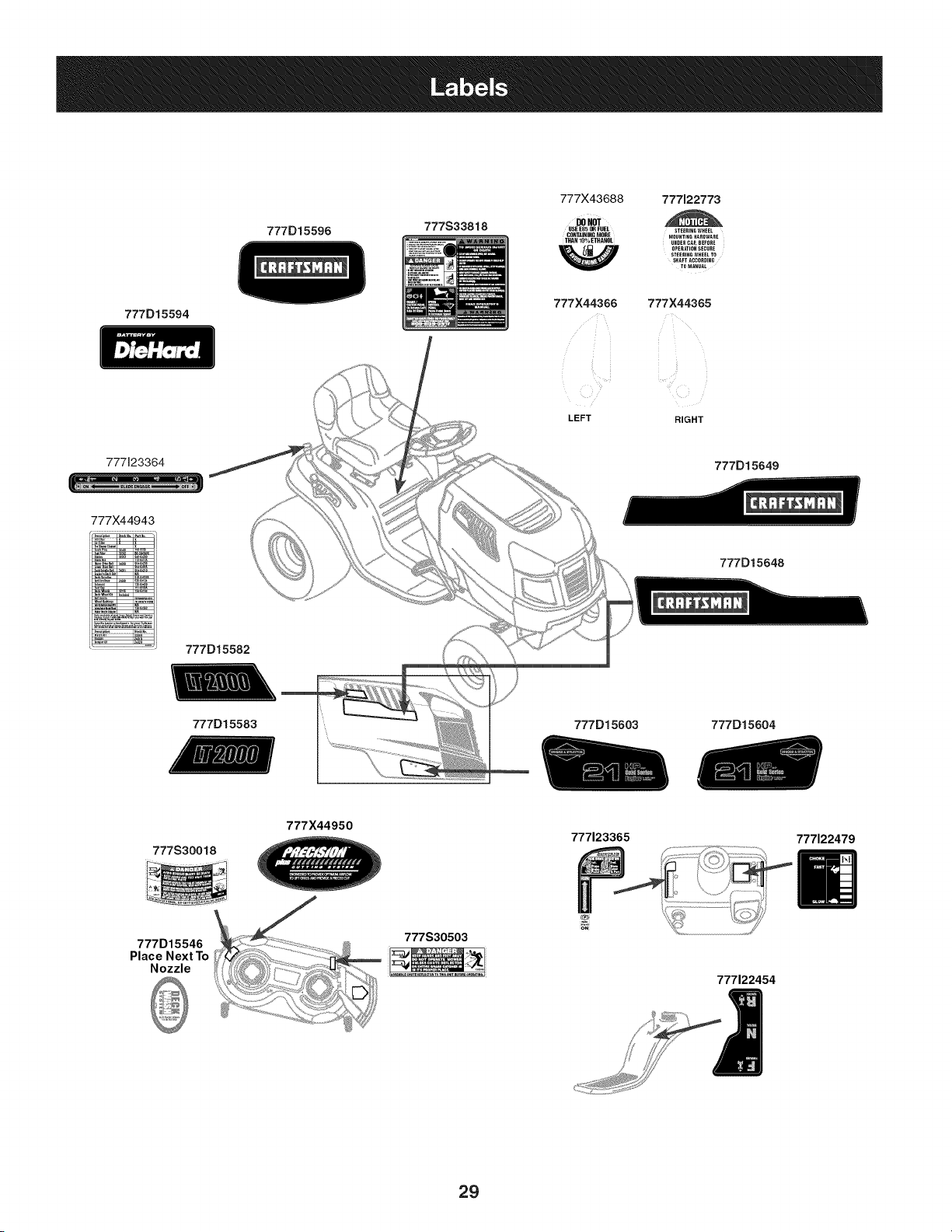
777D15594
777D15596
777S33818
777X43688 777122773
DONOT
USE EN5OR FUEL STEERINGWHEEL
CONTAININGMORE MOUNTINGHARDWARE
THAN 10% ETHANOL
UNDER CAR BEFORE
OPERATIONSECURE
STEERING WHEEL TO
SHAFT ACCORDING
TO MANUAL
777X44366 777X44365
LEFT RIGHT
777123364
777)(44943
777D15582
777D15649
777D15648
777D15583
777D15603 777D15604
777S30018
777X44950
777123365
777122479
777D15546
Place Next To
Nozzle
777S30503
777122454
29
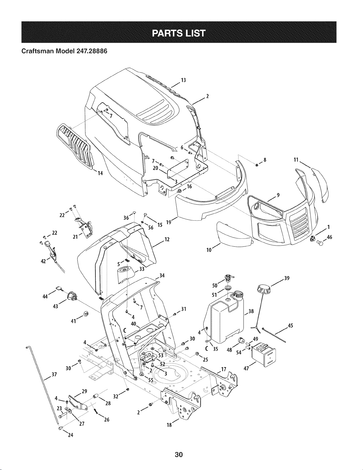
Craftsman IViodel 247.28886
10
I
25
35
46
3O
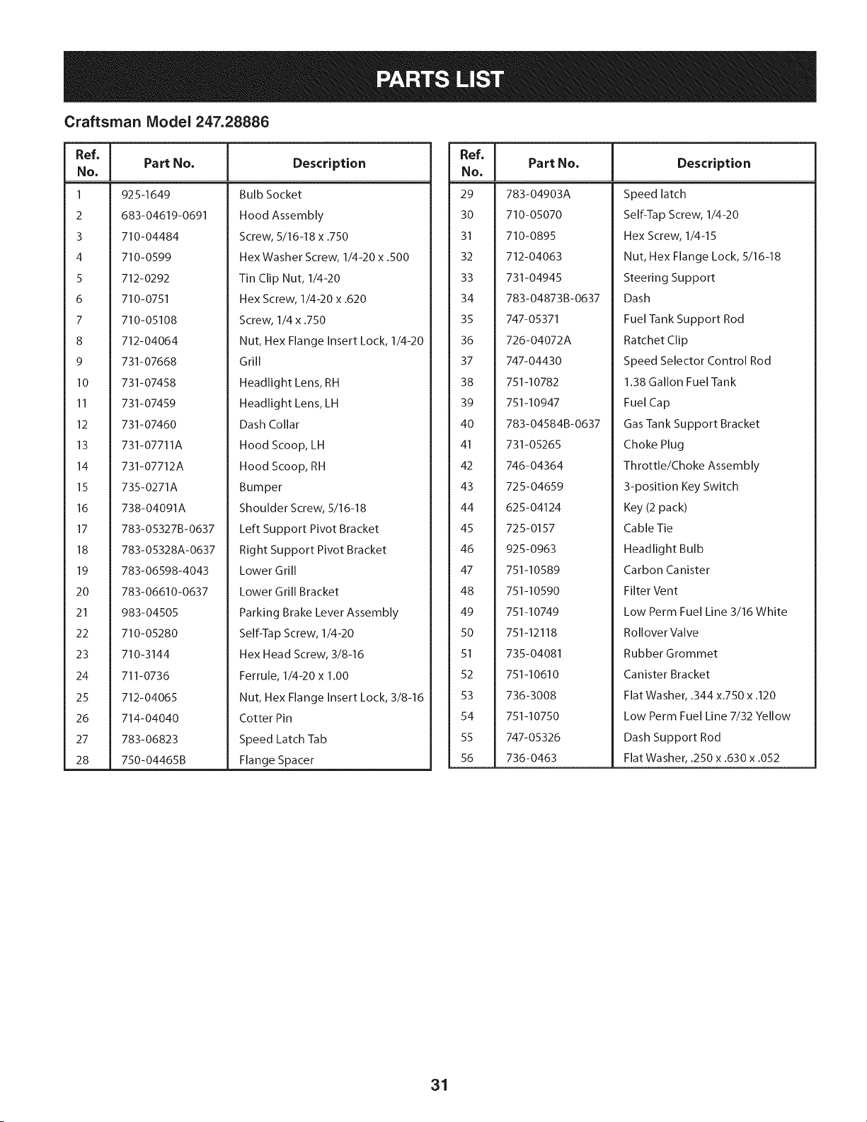
Craftsman Model 247.28886
Ref, I
No,
1 925-I 649
2 683-04619-0691
3 710-04484
4 710-0599
5 712-0292
6 710-0751
7 710-05108
8 712-04064
9 731-07668
lO 731-07458
II 731-07459
12 731-07460
13 731-07711A
14 731-07712A
15 735-0271A
16 738-04091A
17 783-05327B-0637
18 783-05328A-0637
19 783-06598-4043
20 783-06610-0637
21 983-04505
22 710-05280
23 710-3144
24 711-0736
25 712-04065
26 714-04040
27 783-06823
28 750-04465B
Part No. Description
Bulb Socket
Hood Assembly
Screw, 5/16-18 x .750
Hex Washer Screw, 1/4-20 x .500
Tin Clip Nut, 1/4-20
Hex Screw, 1/4-20 x .620
Screw, 1/4 x .750
Nut, Hex Flange Insert Lock, 1/4-20
Grill
Headlight Lens, RH
Headlight Lens, LH
Dash Collar
Hood Scoop, LH
Hood Scoop, RH
Bumper
Shoulder Screw, 5/16-18
Left Support Pivot Bracket
Right Support Pivot Bracket
Lower Grill
Lower Grill Bracket
Parking Brake Lever Assembly
Self-Tap Screw, 1/4-20
Hex Head Screw, 3/8-16
Ferrule, 1/4-20 x 1.00
Nut, Hex Flange Insert Lock, 3/8-16
Cotter Pin
Speed Latch Tab
Flange Spacer
Ref, ]
NO,
29 783-04903A
30 710-05070
31 710-0895
32 712-04063
33 731-04945
34 783-04873B-0637
35 747-05371
36 726-04072A
37 747-04430
38 751-10782
39 751-10947
40 783-04584B-0637
41 731-05265
42 746-04364
43 725-04659
44 625-04124
45 725-0157
46 925-0963
47 751-10589
48 751-10590
49 751-10749
50 751-12118
51 735-04081
52 751-10610
53 736-3008
54 751-10750
55 747-05326
56 736-0463
Part No, Description
Speed latch
Self-Tap Screw, 1/4-20
Hex Screw, 1/4-15
Nut, Hex Flange Lock, 5/16-18
Steering Support
Dash
Fuel Tank Support Rod
Ratchet Clip
Speed Selector Control Rod
1.38 Gallon Fuel Tank
Fuel Cap
Gas Tank Support Bracket
Choke Plug
Throttle/Choke Assembly
3-position Key Switch
Key (2 pack)
Cable Tie
Headlight Bulb
Carbon Canister
Filter Vent
Low Perm Fuel Line 3/16 White
Rollover Valve
Rubber Grommet
Canister Bracket
Flat Washer, .344 x.750 x .120
Low Perm Fuel Line 7/32 Yellow
Dash Support Rod
Flat Washer, .250 x .630 x .052
31
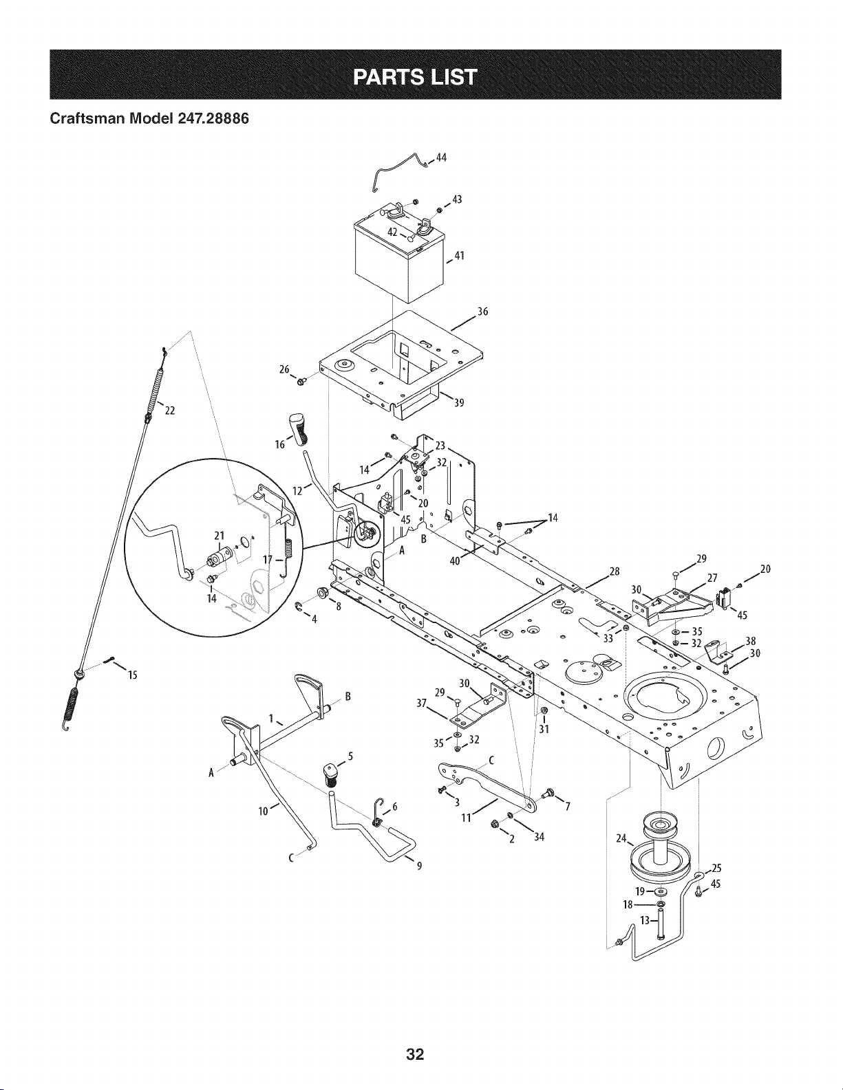
Craftsman IViodel 247.28886
26
15
21
14
37
29
29
27
45
30
32
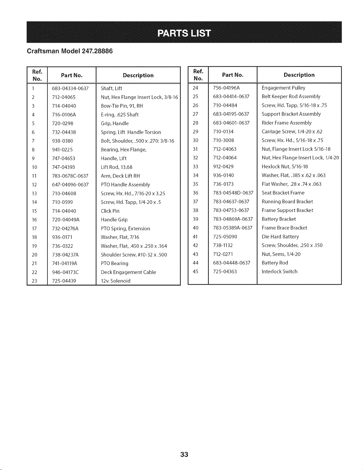
Craftsman Model 247.28886
Ref, ]
No,
1 683-04334-0637
2 712-04065
3 714-04040
4 716-0106A
5 720-0298
6 732-04438
7 938-0380
8 941-0225
9 747-04653
10 747-04393
11 783-0678C-0637
12 647-04096-0637
13 710-04608
14 710-0599
15 714-04040
16 720-04049A
17 732-04276A
18 936-0171
19 736-0322
20 738-04237A
21 741-04119A
22 946-04173C
23 725-04439
Part No. Description
Shaft, Lift
Nut, Hex Flange Insert Lock, 3/8-16
Bow-Tie Pin, 91, RH
E-ring, .625 Shaft
Grip, Handle
Spring, Lift Handle Torsion
Bolt, Shoulder, .500 x .270:3/8-16
Bearing, Hex Flange,
Handle, Lift
Lift Rod, 13.68
Arm, Deck Lift RH
PTO Handle Assembly
Screw, Hx. Hd., 7/16-20 x 3.25
Screw, Hd. Tapp, 1/4-20 x .5
Click Pin
Handle Grip
PTO Spring, Extension
Washer, Flat, 7/16
Washer, Flat, .450 x .250 x .164
Shoulder Screw, #10-32 x .500
PTO Bearing
Deck Engagement Cable
12v. Solenoid
Ref, I
No,
24 756-04196A
25 683-04414-0637
26 710-04484
27 683-04195-0637
28 683-04601-0637
29 710-0134
30 710-3008
31 712-04063
32 712-04064
33 912-0429
34 936-0140
35 736-0173
36 783-04548D-0637
37 783-04637-0637
38 783-04753-0637
39 783-04869A-0637
40 783-05389A-0637
41 725-05090
42 738-1132
43 712-0271
44 683-04448-0637
45 725-04363
Part No. Description
Engagement Pulley
Belt Keeper Rod Assembly
Screw, Hd. Tapp, 5/16-18 x .75
Support Bracket Assembly
Rider Frame Assembly
Carriage Screw, 1/4-20 x .62
Screw, Hx. Hd., 5/16-18 x .75
Nut, Flange Insert Lock 5/16-18
Nut, Hex Flange Insert Lock, 1/4-20
Hexlock Nut, 5/16-18
Washer, Flat, .385 x .62 x .063
Flat Washer, .28 x .74 x .063
Seat Bracket Frame
Running Board Bracket
Frame Support Bracket
Battery Bracket
Frame Brace Bracket
Die Hard Battery
Screw, Shoulder, .250 x .150
Nut, Seres, 1/4-20
Battery Rod
Interlock Switch
33
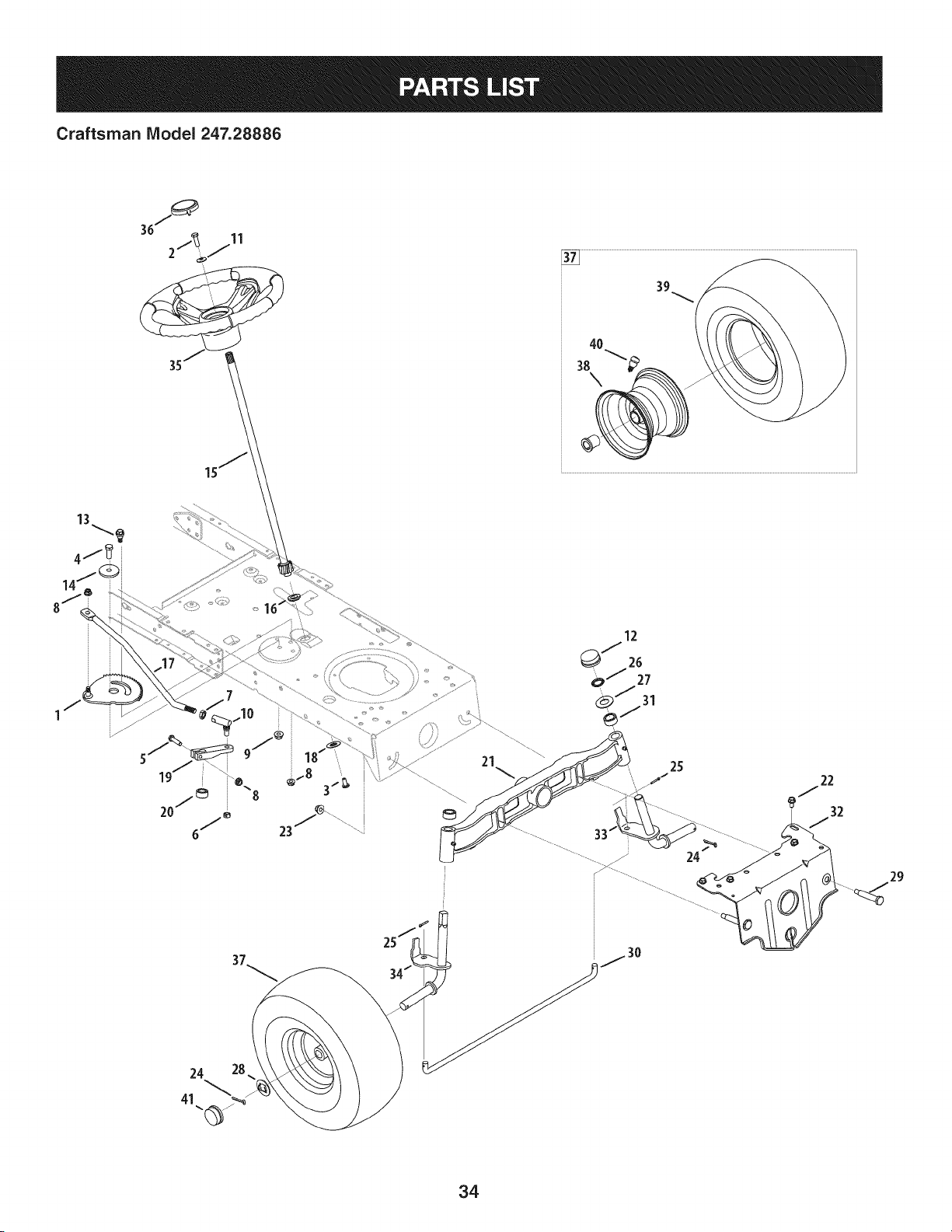
Craftsman Model 247.28886
39
40
13
34/
25
i
j30
24
22
32
29
34

Craftsman Model 247.28886
Ref, I
No,
1 617-04094
2 710-0643
3 710-1309
4 710-3094A
5 710-3180
6 912-0214
7 912-0240
8 712-04063
9 712-04065
10 923-0448A
11 736-0242
12 731-04693
13 738-04141
14 738-04162A
15 738-0919A
16 941-04124
17 747-05385
18 948-0389
19 748-04065-0637
20 748-04068
21 719-04177A
Part No. Description
Gear Assembly, Steering
Screw, 5/16-18, 1.00, GrS, Lock
Screw, Mach, 5/16-18, 0.750
Hex Head Screw, 3/8-16 x 1.00
Screw, 5/16-18, 1.75, Gr5
Nut, Jam Lock, 3/8-24
Nut, Jam, 7/16-20, Gr2
Nut, Flange Lock, 5/16-18, Grf
Nut, Flange Lock, 3/8-16, Grf
Ball Joint, 7/16-20, Lock
Washer, Bell, .340 x .872 x .060
Hub Cap
Shoulder Screw, 5/16-18
Shoulder Spacer, .8840 x .190
Steering Shaft, 5/8 Spline x 21.86
Bearing, Flange, Hex 5/8
Drag Link, Steering
Cap, 1.25 x .16
Steering, Block
Spacer, .710 ID x .125 OD x .56
Pivot Bar Axle Assembly
Ref, I
NO,
22 710-04484
23 712-04065
24 714-04039A
25 914-0474
26 726-04035
27 936-0316
28 736-04228A
29 738-04128
30 747-04299A
31 748-04068
32 783-05326B-0637
33 938-04013
34 938-04014A-0637
35 631-04008A
36 731-06825
37 634-04639-0961
38 934-04634-4042
39 734-1731-0901
40 934-0255
41 931-0484A
Part No. Description
Screw, 5/16-18, 0.750
Nut, Flange Lock, 3/8-16, GrF
Pin, Cotter, 5/32, 1.25
Pin, Cotter, 1/8 x 0.75
Push Cap, 3/4
Washer, Flat, .78 x 1.59 x .060
Washer, Flat, .781 x 1.59
Screw, Shlder, .500 x 2.380, 3/8-16
Tie Rod
Spacer, .71 x .125 x .56
Pivot Bar Bracket
Axle Assembly LH
Axle Assembly RH
Steering Wheel, Standard Grip
Cap, Steering Wheel (Crafts. logo)
Wheel Assembly
Rim
Tire, 15 x 6 x 6 Sq. Shoulder
Valve Stem
Hub Cap
35
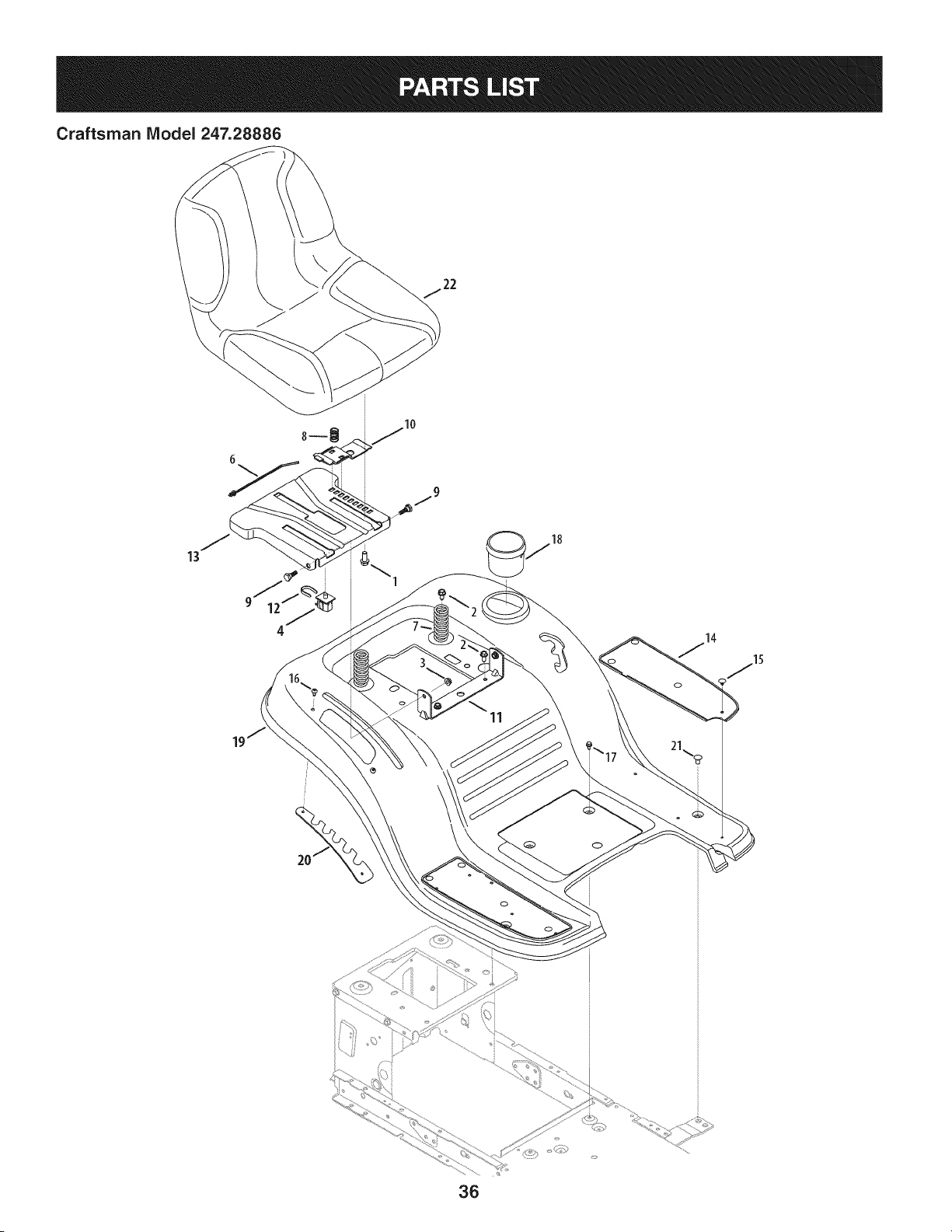
Craftsman Model 247.28886
13
\
11
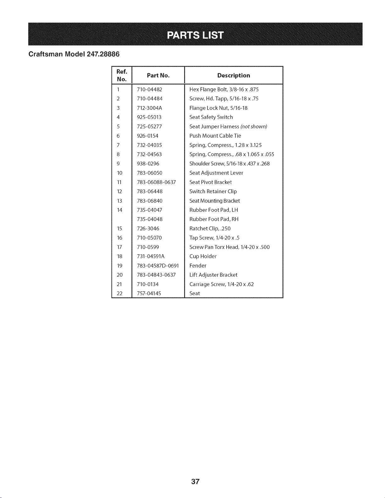
Craftsman Model 247.28886
Ref, [
No,
I 710-04482
2 710-04484
3 712-3004A
4 925-05013
5 725-05277
6 926-0154
7 732-04035
8 732-04563
9 938-0296
10 783-06050
11 783-06088-0637
12 783-06448
13 783-06840
14 735-04047
735-04048
15 726-3046
16 710-05070
17 710-0599
18 731-04591A
19 783-04587D-0691
20 783-04843-0637
21 710-0134
22 757-04145
Part No. Description
Hex Flange Bolt, 3/8-16 x .875
Screw, Hd.-lapp, 5/16-18 x .75
Flange Lock Nut, 5/16-18
Seat Safety Switch
Seat Ju m per Ha mess (not shown)
Push Mount Cable Tie
Spring, Compress., 1.28 x 3.125
Spring, Compress., .68 x 1.065 x .055
Shoulder Screw, 5/16-18 x .437 x .268
Seat Adjustment Lever
Seat Pivot Bracket
Switch Retainer Clip
Seat Mounting Bracket
Rubber Foot Pad, LH
Rubber Foot Pad, RH
Ratchet Clip, .250
Tap Screw, 1/4-20 x .5
Screw Pan Torx Head, 1/4-20 x .500
Cup Holder
Fender
Lift Adjuster Bracket
Carriage Screw, 1/4-20 x .62
Seat
37
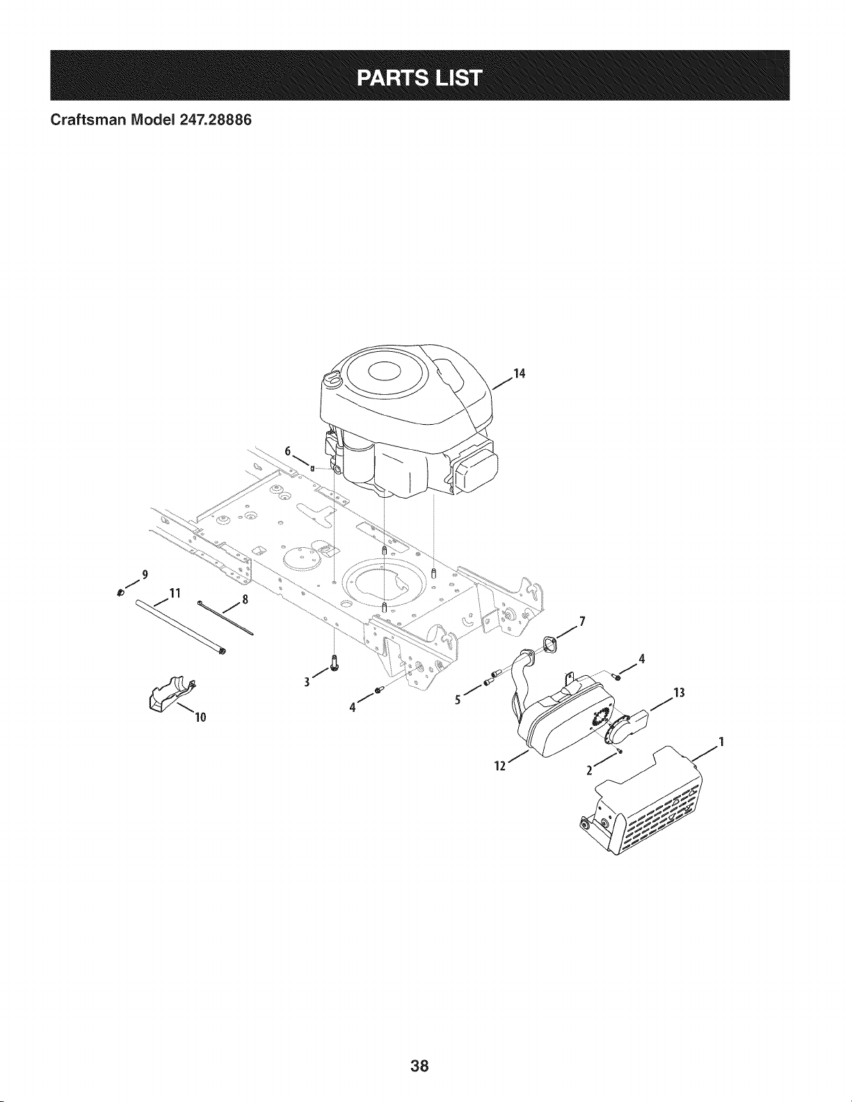
Craftsman IViodel 247.28886
13
38
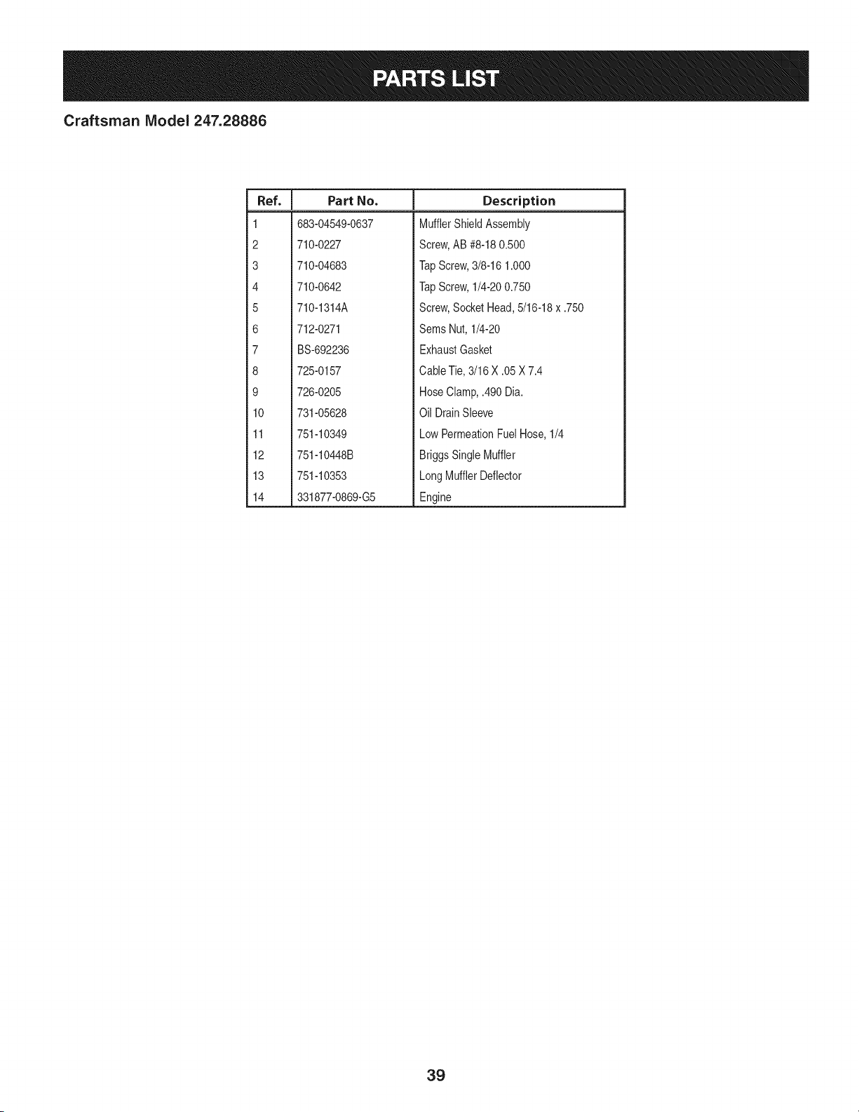
Craftsman IViodel 247.28886
I
Ref.
I Part No.
1 683-04549-0637
2 710-0227
3 710-04683
4 710-0642
5 710-1314A
6 712-0271
7 BS-692236
8 725-0157
9 726-0205
10 731-05628
11 751-10349
12 751-10448B
13 751-10353
14 331877-0869-G5
Descriptien
MufflerShieldAssembly
Screw,AB #8-180.500
TapScrew,3/8-16 1.000
TapScrew,1/4-200.750
Screw,SocketHead,5/16-18x .750
Sems Nut, 1/4-20
ExhaustGasket
CableTie,3/16 X .05 X 7.4
HoseClamp,.490 Dia.
Oil DrainSleeve
LowPermeationFuelHose,1/4
BriggsSingleMuffler
LongMufflerDeflector
Engine
39
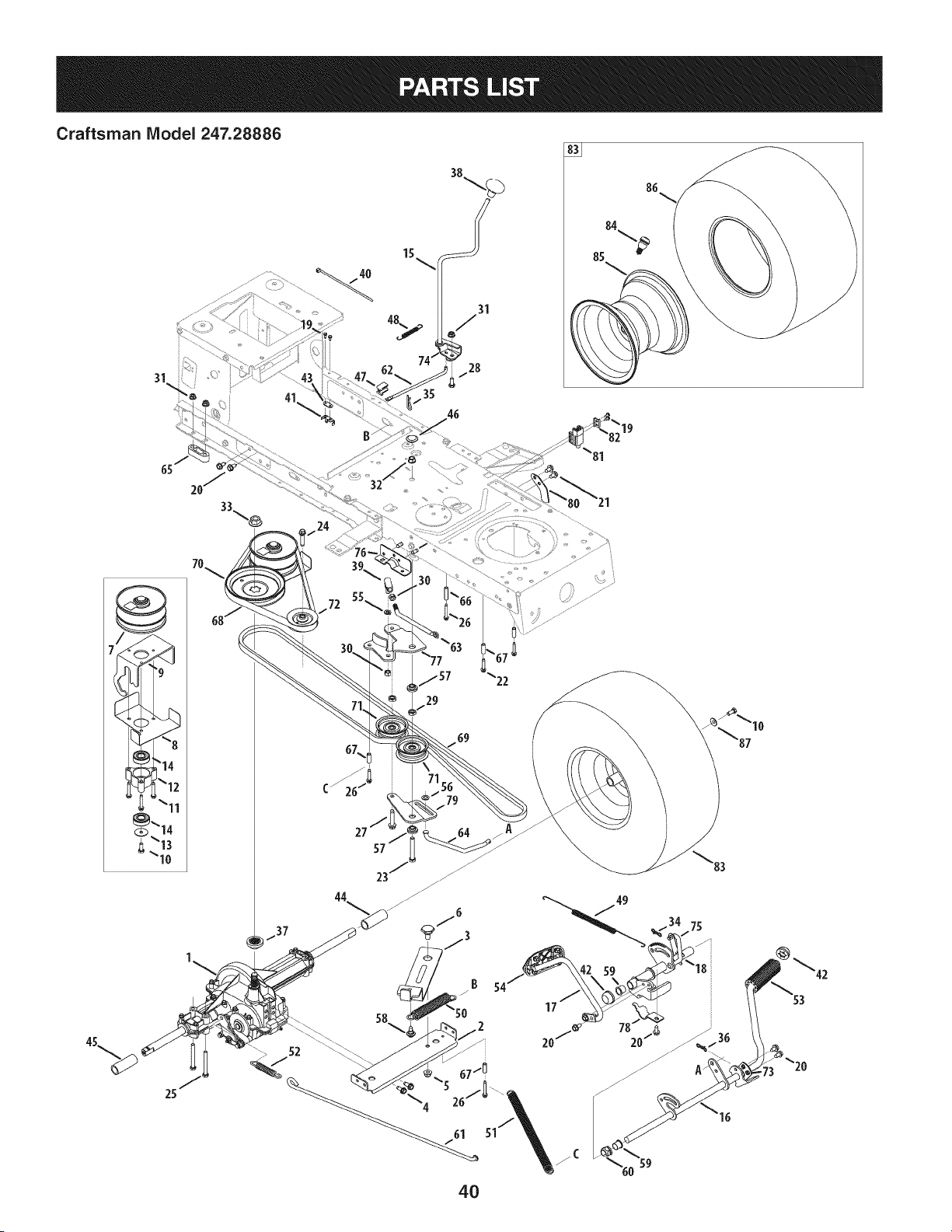
Craftsman Model 247.28886
41
15
35
19
29
B 54
17
4O
20/_

Craftsman Model 247.28886
I
Ref, I Part No.
1 918-04566
2 683-04606
3 683-04684
4 710-1260A
5 712-04065
6 738-0322A
7 956-04015A
8 683-04522
9 683-04612-0637
10 710-0627
11 710-0778
12 718-04261
13 736-0362
14 941-0600
15 647-04035
16 647-04201-0637
17 647-04203A-0637
18 683-04607
19 710-0227
20 710-04484
21 710-0604A
22 710-0809
23 710-0859
24 710-1007
25 710-1266
26 710-1325
27 710-1858A
28 710-3008
29 912-0240
30 712-0241
31 712-04063
32 912-0431
33 712-0700
34 914-0111
35 914-0209
36 714-04040
37 718-04407
38 720-04028
39 923-3018
40 725-0157
41 725-1644
42 726-0214
43 926-0320
44 731-04602
Description
Dr Assembly, Autodrive Lt-5
Auto-drive Bracket Assembly
Idler Bracket Assembly
Tap Screw, 5/16-18 x 0.750
Flange Lock Nut, 3/8-16
Shoulder Screw, .625 x .217
Pulley Assembly, Var. Spd. 4.75 Od
Belt Keeper Assembly
Variable Bracket Assembly
Hex Screw 5/16-24.750
Tap Screw, 1/4-20 1.500
Bearing Cup
Wash, Flat .330 X 1.25 X .06
Ball Bearing, 17 x 40 x 12.6203
Lvr Assembly, Shft
Ped Assembly, Drive, Autodrive
Ped Assembly, Cont, Autodrive
Bracket Assembly, Pedal, Autodrive
Screw, Ab, #8-18, 0.500
Screw, Tt, 5/16-18, .750
Screw, Tt, 5/16-18, 0.625
Screw, Tt, 1/4-20, 1.250
Hex Hd. Screw, 3/8-16, 2.50
Screw, Ttsems, 3/8-16, 1.500
Hex Hd. Screw, 5/16-18, 3.50
Screw, Tt, 1/4-20, 1.625,
Screw, Tt, 3/8-16 x 1.75
Hex Hd. Screw, 5/16-18, .75
Nut, Jam, 7/16-20
Nut, Hex, 3/8-24
Nut, Flange Lock Nut, 5/16-18
Nut, Flange Lock Nut, 3/8-16
Nut, Fig, 9/16-18
Pin, Cot, 3/32, 1.0
Pin, Cotter Int- .125 Dia
Pin, Cot, Bow-Tie 72
Hub, Pulley, 5/8 Spline
Knob, Shft
Ball, Joint
Cable, Tie, 3/16 X .05 X 7.4
Switch, Spring, Short
Cap, Push 5/8
Plate, Insulator Nut
Sleeve, .758 X .821 X 3.3125
|
Ref, I Part No,
45 731-04604
46 731-06330
47 731-06894
48 732-04488
49 732-04612
50 732-04616B
51 732-04764
52 732-0716D
53 735-0239
54 735-0662
55 936-0169
56 936-0185
57 738-0372B
58 738-04091A
59 741-0495
60 741-3065B
61 747-05188
62 747-05243
63 747-05251A
64 747-05415
65 948-0334
66 750-04456
67 750-0566A
68 954-04208
69 954-0467A
70 956-04002
71 756-04224
72 756-04325
73 783-04536B-0637
74 783-04595A
75 783-06278
76 783-06562-0637
77 783-06592A
78 783-06641
79 783-06769
80 783-06807
81 725-04363
82 17962
83 634-0104-0961
84 934-0255
85 634-04369-4042
86 734-1730-0901
87 736-0242
-- 925-04082
Description
Sleeve, .758 X .821 X 2.4375
Plug, Deck Hole, 7/8
Shift Plate Bearing
Spring, Ext, .38 Od X 3.25 Lg
Spring, Extn, .70 Dia X 12.00 Lg
Spring, Extn, .97 Od X 6.18 Lg
Spring, Extn, .56 X 12.05 x .068
Spring, Extn, .59 Od X 4.00 Lg
Pad, Foot, 4.0 Long
Pad, Cont
Wash, Lock, 3/8, Regular Duty
Wash, Flat, .375 X .738 X .063
Spacer, Shoulder, 1.00 X .38 X .38
Screw, Shoulder, A3x.29, Tt, 5/16-18
Bearing, Fig, .630 Idx .695 Od X .60
Bearing, Hex Fig, .628 Id, Split
Rod, Brake, Lt-5 Trans
Rod, Shift, Lt-5 Stretch 46"
Rod, Adj, Idlr, 3/8
Rod, Trans, Footpedal Bypass
Spacer, T-Axle .68
Spacer, .260 X .372 X 1.420 Lg
Spacer, .260 X .375 X 1.030 Lg
Belt, V Typ, 51 X 40.9 Lg Poly
Belt, V Typ, 51, 90.80, Poly
Pulley, Idlr, Flat 7.25 Od
Pulley, Idlr, Flat 2.75 Od
Pulley, Idlr, V-Type X 3.06
Bracket, Ped, Support Lt-5
Bracket, Shft, Adj
Pit, Bracket, Reinforcement
Bracket, Ped, Frame Rh
Bracket, Idlr, Dbl Autodrive
Bracket, Supt, Pedal Stap
Bracket, Idlr, Center Dbl
Pedal Stop Plate
Interlock Switch
Switch Plate
Wheel Assembly, 20 x 8 x 8 Sq. Sh.
Valve Stem
Rim Assembly
Tire, 20 x 8 x 8 Sq. Sh.
Bell Washer, .340 x .872 x .060
Wiring Harness (NotShown)
41
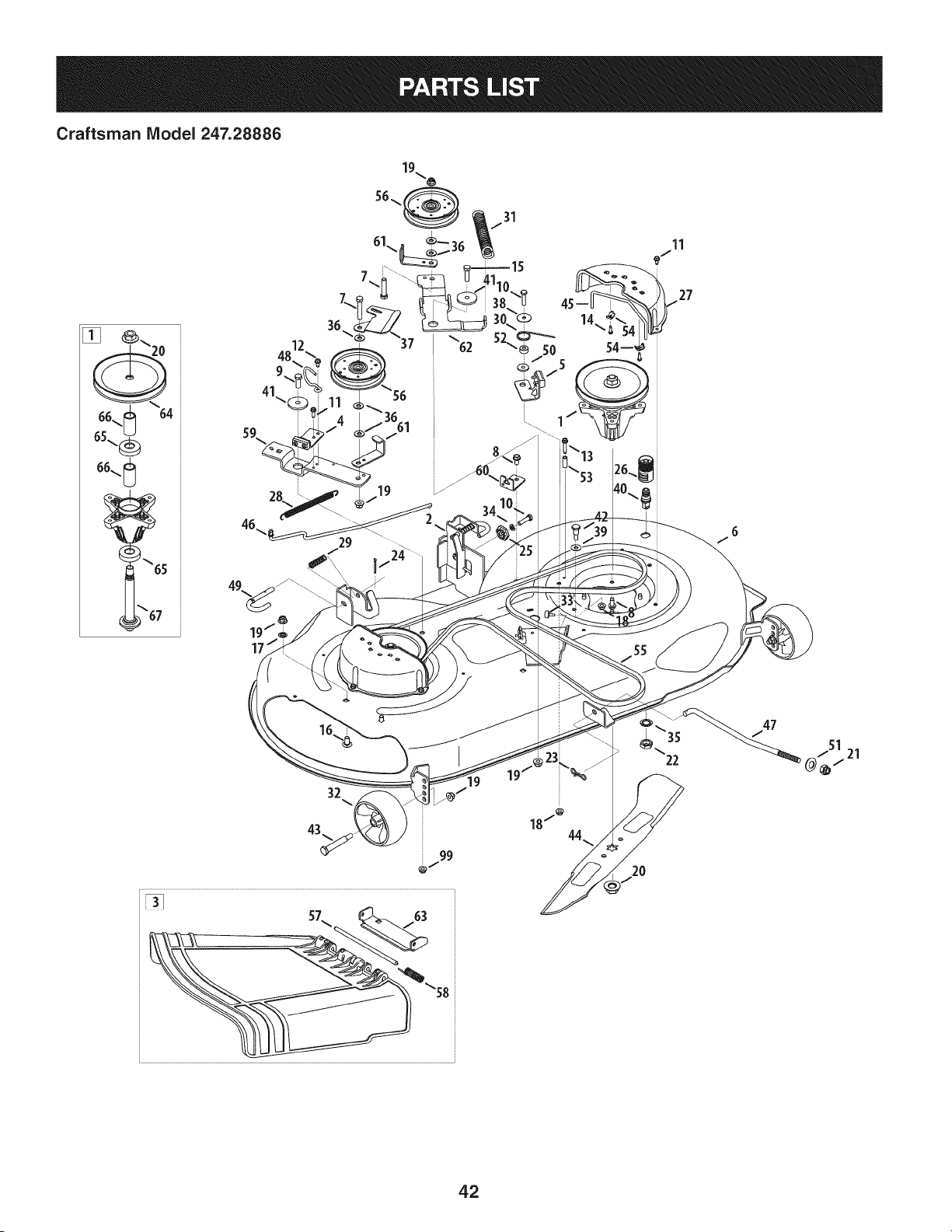
Craftsman Model 247.28886
19-.,6
99
51
/ 21
42
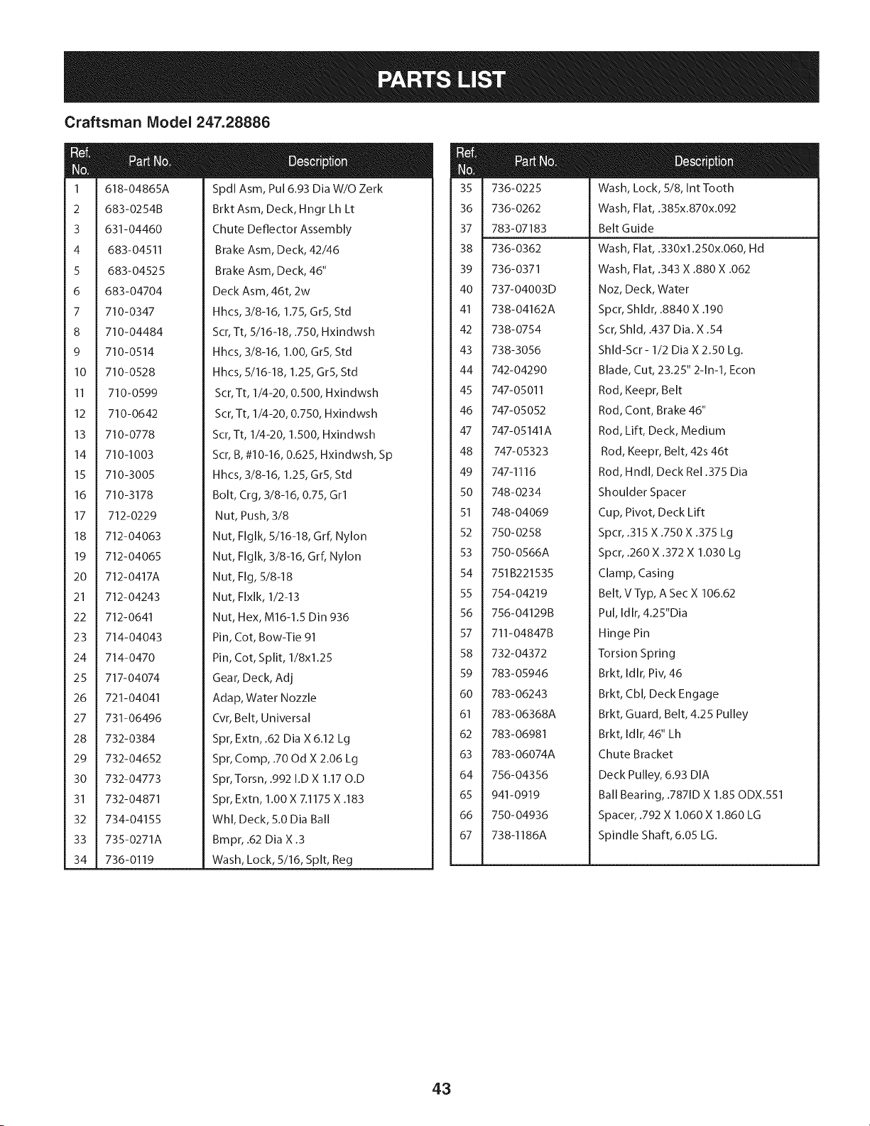
Craftsman Model 247.28886
m
m
1
2
3
4
5
6
7
8
9
10
11
12
13
14
15
16
17
18
19
20
21
22
23
24
25
26
27
28
29
3O
31
32
33
34
618-04865A
683-0254B
631-04460
683-04511
683-04525
683-04704
710-0347
710-04484
710-0514
710-0528
710-0599
710-0642
710-0778
710-1003
710-3005
710-3178
712-0229
712-04063
712-04065
712-0417A
712-04243
712-0641
714-04043
714-0470
717-04074
721-04041
731-06496
732-0384
732-04652
732-04773
732-04871
734-04155
735-0271A
736-0119
Spdl Asm, Pul 6.93 Dia W/O Zerk
Brkt Asm, Deck, Hngr Lh Lt
Chute Deflector Assembly
Brake Asm, Deck, 42/46
Brake Asm, Deck, 46"
Deck Asm, 46t, 2w
Hhcs, 3/8-16, 1.75, GrS, Std
Scr, Tt, 5/16-18, .750, Hxindwsh
Hhcs, 3/8-16, 1.00, GrS, Std
Hhcs, 5/16-18, 1.25, GrS, Std
Scr, Tt, 1/4-20, 0.500, Hxindwsh
Scr, Tt, 1/4-20, 0.750, Hxindwsh
Scr, Tt, 1/4-20, 1.500, Hxindwsh
Scr, B, #10-16, 0.625, Hxindwsh, Sp
Hhcs, 3/8-16, 1.25, GrS, Std
Bolt, Crg, 3/8-16, 0.75, Grl
Nut, Push, 3/8
Nut, Flglk, 5/16-18, Grf, Nylon
Nut, Flglk, 3/8-16, Grf, Nylon
Nut, Fig, 5/8-18
Nut, Flxlk, 1/2-13
Nut, Hex, M16-1.5 Din 936
Pin, Cot, Bow-Tie 91
Pin, Cot, Split, 1/8xl.25
Gear, Deck, Adj
Adap, Water Nozzle
Cvr, Belt, Universal
Spr, Extn, .62 Dia X 6.12 Lg
Spr, Comp, .70 Od X 2.06 Lg
Spr, Torsn, .992 I.D X 1.17 O.D
Spr, Extn, 1.00 X 7.1175 X .183
Whl, Deck, 5.0 Dia Ball
Bmpr, .62 Dia X .3
Wash, Lock, 5/16, Spit, Reg
35 736-0225 Wash, Lock, 5/8, Int Tooth
36 736-0262 Wash, Flat, .385x.870x.092
37 783-07183 Belt Guide
38 736-0362 Wash, Flat, .330xl.250x.060, Hd
39 736-0371 Wash, Flat, .343 X .880 X .062
40 737-04003D Noz, Deck, Water
41 738-04162A Spcr, Shldr, .8840 X .190
42 738-0754 Scr, Shld, .437 Dia. X .54
43 738-3056 Shld-Scr - 1/2 Dia X 2.50 Lg.
44 742-04290 Blade, Cut, 23.25" 2-1n-1, Econ
45 747-05011 Rod, Keepr, Belt
46 747-05052 Rod, Cont, Brake 46"
47 747-05141A Rod, Lift, Deck, Medium
48 747-05323 Rod, Keepr, Belt, 42s 46t
49 747-1116 Rod, Hndl, Deck Re1.375 Dia
50 748-0234 Shoulder Spacer
51 748-04069 Cup, Pivot, Deck Lift
52 750-0258 Spcr, .315 X .750 X .375 Lg
53 750-0566A Spcr, .260 X .372 X 1.030 Lg
54 751 B221535 Clamp, Casing
55 754-04219 Belt, VTyp, A Sec X 106.62
56 756-04129B Pul, Idlr, 4.25"Dia
57 711-04847B Hinge Pin
58 732-04372 Torsion Spring
59 783-05946 Brkt, Idlr, Piv, 46
60 783-06243 Brkt, Cbl, Deck Engage
61 783-06368A Brkt, Guard, Belt, 4.25 Pulley
62 783-06981 Brkt, Idlr, 46" Lh
63 783-06074A Chute Bracket
64 756-04356 Deck Pulley, 6.93 DIA
65 941-0919 Ball Bearing, .7871D X 1.85 ODX.551
66 750-04936 Spacer, .792 X 1.060 X 1.860 LG
67 738-1186A Spindle Shaft,6.05 LG.
43
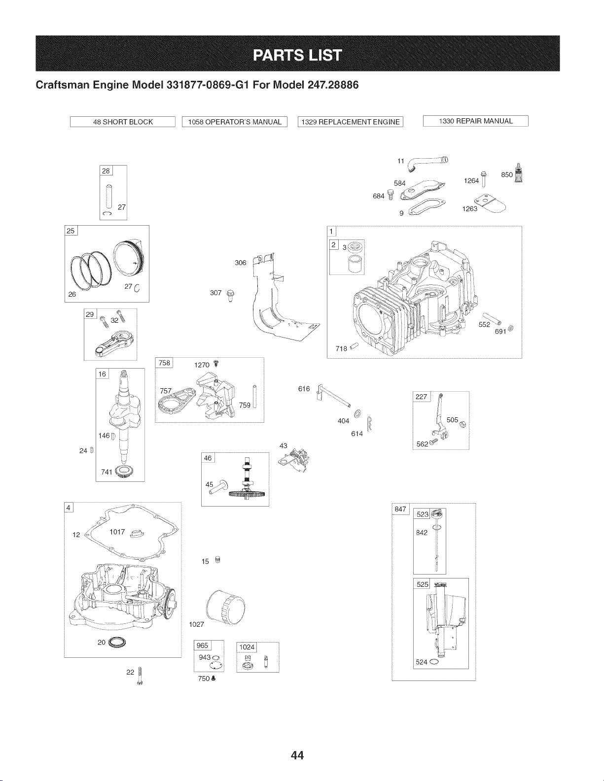
Craftsman Engine IViodel 331877=0869=G1 For IViodel 247.28886
48 SHORT BLOCK
1058 OPERATOR'S MANUAL ] I1329 REPLACEMENT ENGINE ]
1330 REPAIR MANUAL
26
12 1017_i_2__'_ _-'-.__i i
200
22
306
307
U
k _
15 _
1027
75O &
43
616
11 ,_
584 ..-/_. __ 1264
9 _ 1263 _-. y
552 _
691 _
718
404 ion.,505
614 _-,'-_¢,_
562 _ _"
847 _
524 d_7,
44
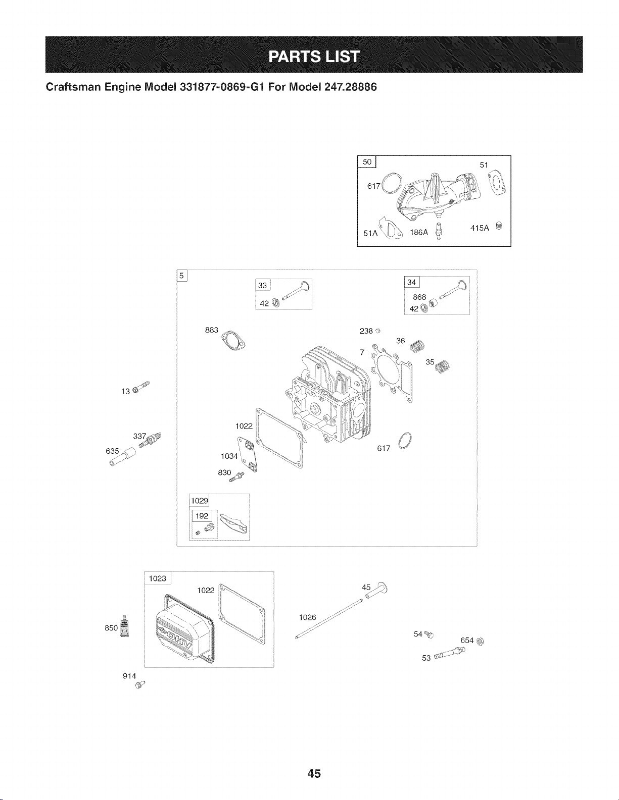
Craftsman Engine Model 331877=0869=G1 For Model 247.28886
5__ 51
51A
186A _ 415A
13_
635_
883
1022
617
i1029}
85O
102
914
1026 _
54%
654 _
53 .......
45
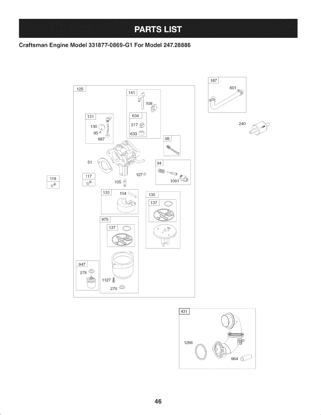
Craftsman Engine IViodel 331877-0869-G1 For IViodel 247.28886
125
13o 1
95 '_ _
987
51
lO2
1270
1091 {{L#
947
276 <_')
_ 1127
_ 276 '-<_
601
24O
1266
46
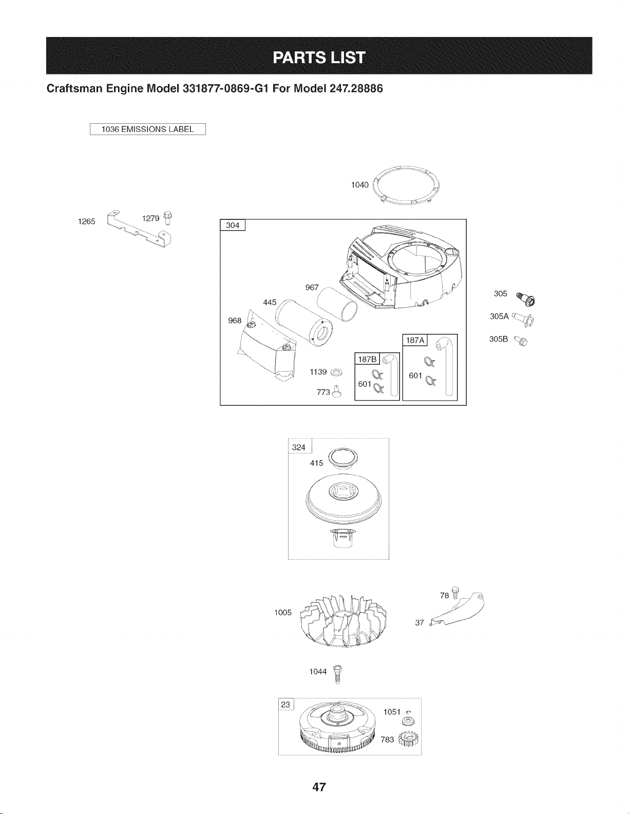
Craftsman Engine IViodel 331877=0869=G1 For IViodel 247.28886
1036 EMiSSiONS LABEL
1265
1139 _._,
305
UZ_--..
305A -.. 7_',
305B _._
,324 i _,
415 _//
:!!!i!!--_
\ .J
1005
78 _¢
37 '_f_
1044
47
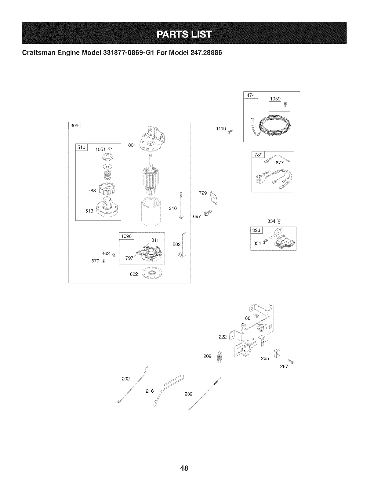
Craftsman Engine IViodel 331877-0869-G1 For IViodel 247.28886
309
1051 <"
783
513
801
310 iii
462 _;
579 _
802
729
697 _
1119
474
334
851
216
2O9
,,,_/ 232
265
267
48
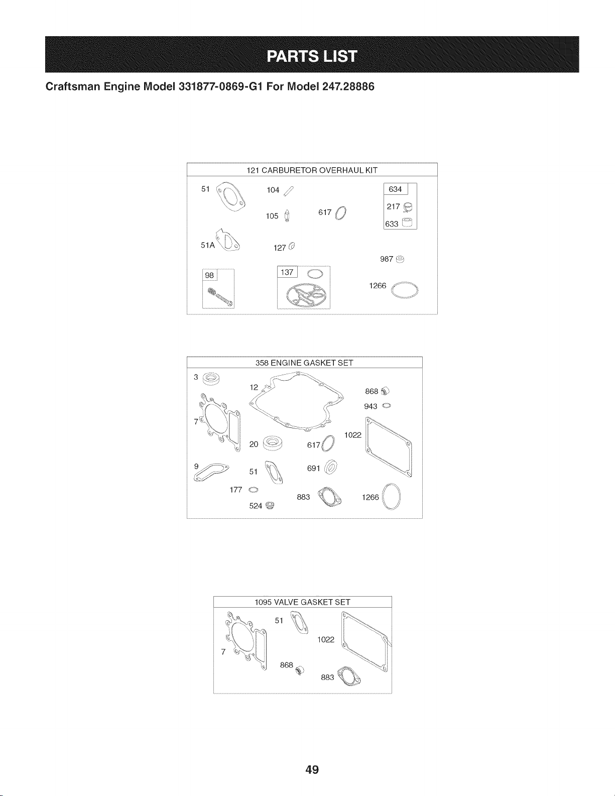
Craftsman Engine Model 331877=0869=G1 For Model 247.28886
51
121 CARBURETOR OVERHAUL KIT
104 _lO50 61__,
127 (_'
987 4_b
, 1266 _ ;_" ;_
ti
/
358 ENGINE GASKET SET
12
1o22
,_
691 _'7//'
1266
1095 VALVE GASKET SET
51
1022
49

Craftsman Engine Model 331877=0869=G1 For Model 247.28886
I
Ref.
I Part No.
NO,
I
1 794128
2 399265
3 391086s
4 697188
5 796026
7 794114
9 697109
11 794683
12 697110
13 793988
15 690946
16 797579
20 795387
22 692125
23 698281
24 796335
25 795858
795877
26 794126
794127
27 698469
28 795861
29 794122
32 791118
33 792868
34 791935
35 691279
36 691279
37 699882
42 499586
43 691968
45 690564
46 793880
48 795446
50 796180
51 692137
51A 794312
53 690227
54 691148
78 691693
94 793610
95 690718
Description
Cylinder Assembly
Bushing/Seal Kit (Magneto Side)
Seal-Oil (Magneto Side)
Sump-Engine
Head-Cylinder
Gasket-Cylinder Head
Gasket-Breather
Tube-Breather
Gasket-Crankcase
Screw (Cylinder Head)
Plug-Oil Drain
Crankshaft
Seal-Oil (PTO Side)
Screw (Crankcase Cover/Sump)
Flywheel
Key-Flywheel (Steel)
Piston Assembly (Standard)
Piston Assembly (020" Oversize)
Ring Set (Standard)
Ring Set (.020" Oversize)
Lock-Piston Pin
Pin-Piston
Rod-Connecting
Screw (Connecting Rod)
Valve-Exhaust
Valve-Intake
Spring-Valve (Intake)
Spring-Valve (Exhaust)
Guard-Flywheel
Keeper-Valve
Slinger-Governor/Oil
Tappet-Va Ive
Camshaft
Short Block
Manifold-Intake
Gasket-Intake
Gasket-Intake
Stud (Carburetor)
Screw (Intake Manifold)
Screw (Flywheel Guard)
Kit-Idle Mixture
Screw (Throttle Va Ive)
Ref,
No,
98 695408
104 694918
105 696136
108 695419
117 796251
118 791406
121 796184
125 796587
127 690727
130 792747
131 792765
133 694914
135 698780
137 698781
141 792777
146 691639
186 794873
187 791805
187A 791806
187B 791744
188 691693
192 691986
202 691841
209 692208
216 691840
217 695409
222 694042
227 691374
232 691842
238 691843
240 394358s
265 691024
267 794904
276 695410
304 798670
305 697102
305A 793376
305B 795891
306 794953
307 691693
309 693551
I Part No, Description
Kit-Idle Speed
Pin-Float Hinge
Valve-Float Needle
Valve-Choke
Jet-Main (Standard)
Jet-Main (High Altitude)
Kit-Carburetor Overhaul
Carburetor
Plug-Welch
Va Ive-Th rottle
Kit-Throttle Shaft
Float-Carburetor
Tube-Fuel Transfer
Gasket-Float Bowl
Kit-Choke Shaft
Key-Timing
Hose-Connector (Intake Manifold)
Line-Fuel (Formed) (Cut to Length)
Line-Fuel (Formed) (21") (Cut to Length)
Line-Fuel (Formed) (14") (Cut to Length)
Screw (Control Bracket)
Adjuster-Rocker Arm
Link-Mechanical Governor
Spring-Governor (Green)
Link-Choke
Spring-Choke Return
Bracket-Control
Lever-Governor Control
Spring-Governor Link
Cap-Valve
Filter-Fuel
Clamp-Casing
Screw (Casing Clamp)
Washer-Sealing
Housing-Blower
Screw (Blower Housing) (1/4-20x1.14)
Screw (Blower Housing) (1/4-20x.68)
Screw (Blower Housing) (Blower Housing to
Elbow)
Shield-Cylinder
Screw (Cylinder Shield)
Motor-Starter
5O

Craftsman Engine Model 331877-0869-G1 For Model 247.28886
I Part No. Description
Ref. Ref.
No. I No.
310 690323
311 497608
324 796309
333 795315
334 691061
337 491055s
358 796187
404 691691
415 794129
415A 794903
431 799043
445 793569
462 691261
474 696459
503 691532
505 691251
510 693699
513 692024
523 699908
524 691032
525 697184
552 697144
562 691119
579 691029
584 794682
601 791850
614 691620
616 692012
617 692138
633 699813
634 698779
635 691909
654 690958
684 697157
691 692407
697 791680
718 690959
729 691224
741 697128
750 790832
757 793242
758 793763
Screw (Starter Motor)
Brush Set
Screen/Cup Assembly
Armature-Magneto
Screw (Magneto Armature)
Plug-Spark
Gasket Set-Engine
Washer (Governor Crank)
Plug (Cover/Retainer)
Plug (Intake Manifold)
Elbow-Intake
Filter-Air Cleaner Cartridge
Washer (Starter Cable)
Alternator
Strap-Starter
Nut (Governor Control Lever)
Drive-Sta rter
Clutch-Drive
Dipstick
Seal-Dipstick Tube
Tube-Dipstick
Bushing-Governor Crank
Screw (Governor Control Lever)
Nut (Starter Cable)
Cover-Breather Passage
Hose-Clamp (Green)
Pin-Cotter (Governor Crank)
Crank-Governor
Seal-O Ring (Intake Manifold) (Red)
Seal-Choke/Throttle (Choke Shaft)
Spring/Seal Assembly
Boot-Spark Plug
Nut (Carburetor)
Screw (Breather Passage Cover)
Seal-Governor Shaft
Screw (Drive Cap)
Pin-Locating
Clip-Wire
Gear-Timing
Screw (Oil Pump Cover)
Link-Counterweight
Counterweight
I Part No.
759 697392
773 796448
783 693713
789 698329
797 693167
801 691283
802 691286
830 691095
842 691031
847 790442
850 100106
851 692424
868 690968
877 790544
883 692236
914 697551
943 690589
947 699915
964 799159
965 499613
967 793685
968 795757
975 699502
987 698777
1005 796084
1017 796981
1022 272475s
1023 797421
1024 794644
1026 692003
692011
1027 492932s
1029 691751
1034 690822
1036
1040
1044
1051
1058
1059
1090
Description
Pin-Counterweight
Retainer (Fuel Pump)
Gear-Pinion
Harness-Wiring
Nut (Brush Retainer)
Cap-Drive
Cap-End
Stud-Rocker Arm
Seal-O Ring (Dipstick Tube)
Dipstick/Tube Assembly
Sealant-Liquid
Terminal-Spark Plug
Seal-Valve
Wire/Connector-Alternator
Gasket-Exhaust
Screw (Rocker Cover)
Seal-O Ring (Oil Pump Cover)
Solenoid-Fuel
Cap-Connector
Cover-Oil Pump
Filter-Pre Cleaner
Cover-Air Cleaner
Bowl-Fuel
Seal-Throttle Shaft
Fan-Flywheel
Screen-Oil Pump
Gasket-Rocker Cover
Cover-Rocker
Pump-Oil
Rod-Push (Intake)
Rod-Push (Exhaust)
Filter-Oil
Arm-Rocker
Guide-Push Rod
Label-Emissions (Available from a Briggs & Stratton
Authorized Dealer)
698368
698139
691265
276344
698516
691293
Plate-Trim
Screw (Flywheel)
Ring-Retaining
Operator's Manual
Kit-Screw/Washer (Alternator)
Retainer-Brush
51
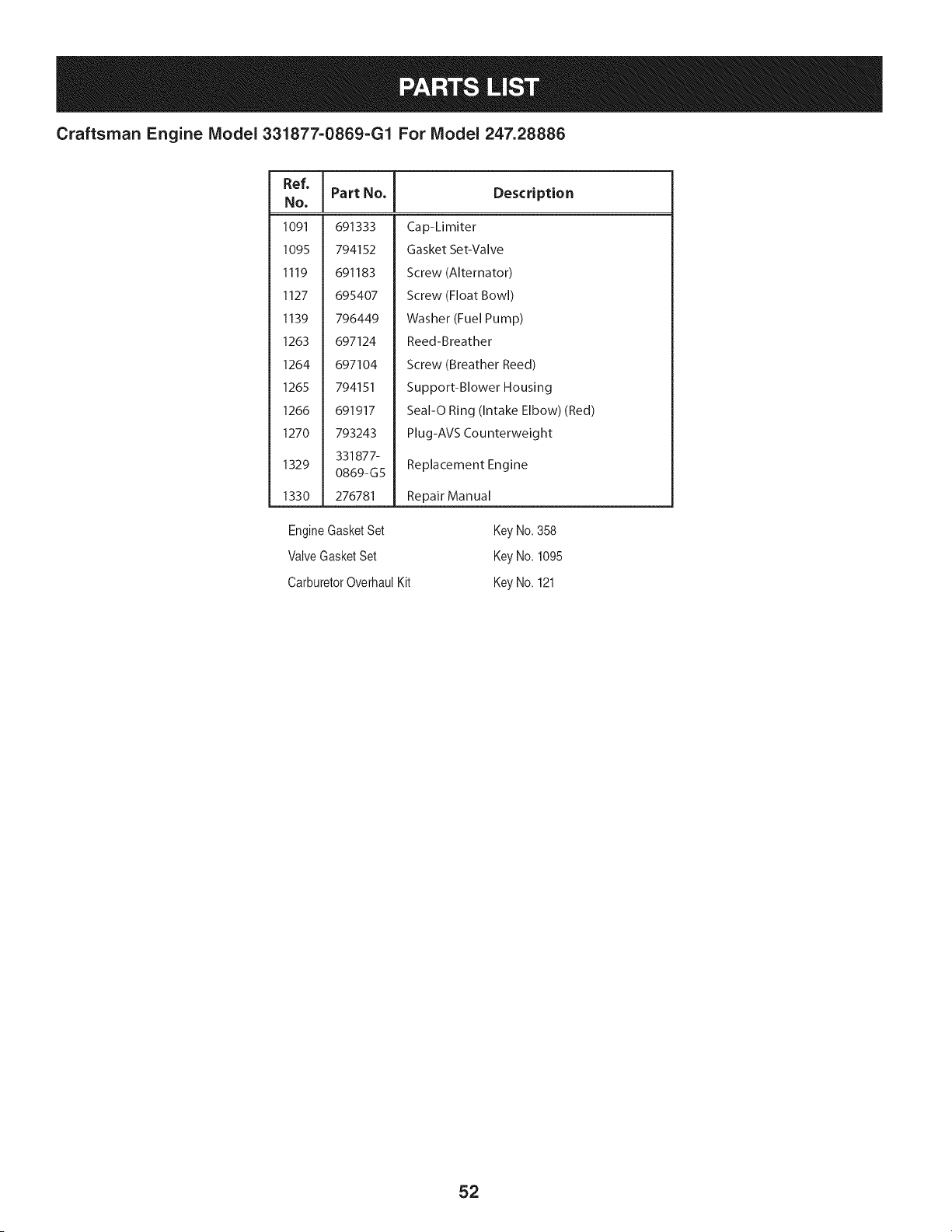
Craftsman Engine Model 331877=0869=G1 For Model 247.28886
Ref,
No,
1091 691333
1095 794152
1119 691183
1127 695407
1139 796449
1263 697124
1264 697104
1265 794151
1266 691917
1270 793243
331877-
1329
0869-G5
1330 276781
I Part No. Description
Cap-Limiter
Gasket Set-Valve
Screw (Alternator)
Screw (Float Bowl)
Washer (Fuel Pump)
Reed-Breather
Screw (Breather Reed)
Support-Blower Housing
Seal-O Ring (Intake Elbow) (Red)
Plug-AVS Counterweight
Replacement Engine
Repair Manual
EngineGasketSet
ValveGasketSet
CarburetorOverhaulKit
Key No.358
Key No.1095
Key No.121
52
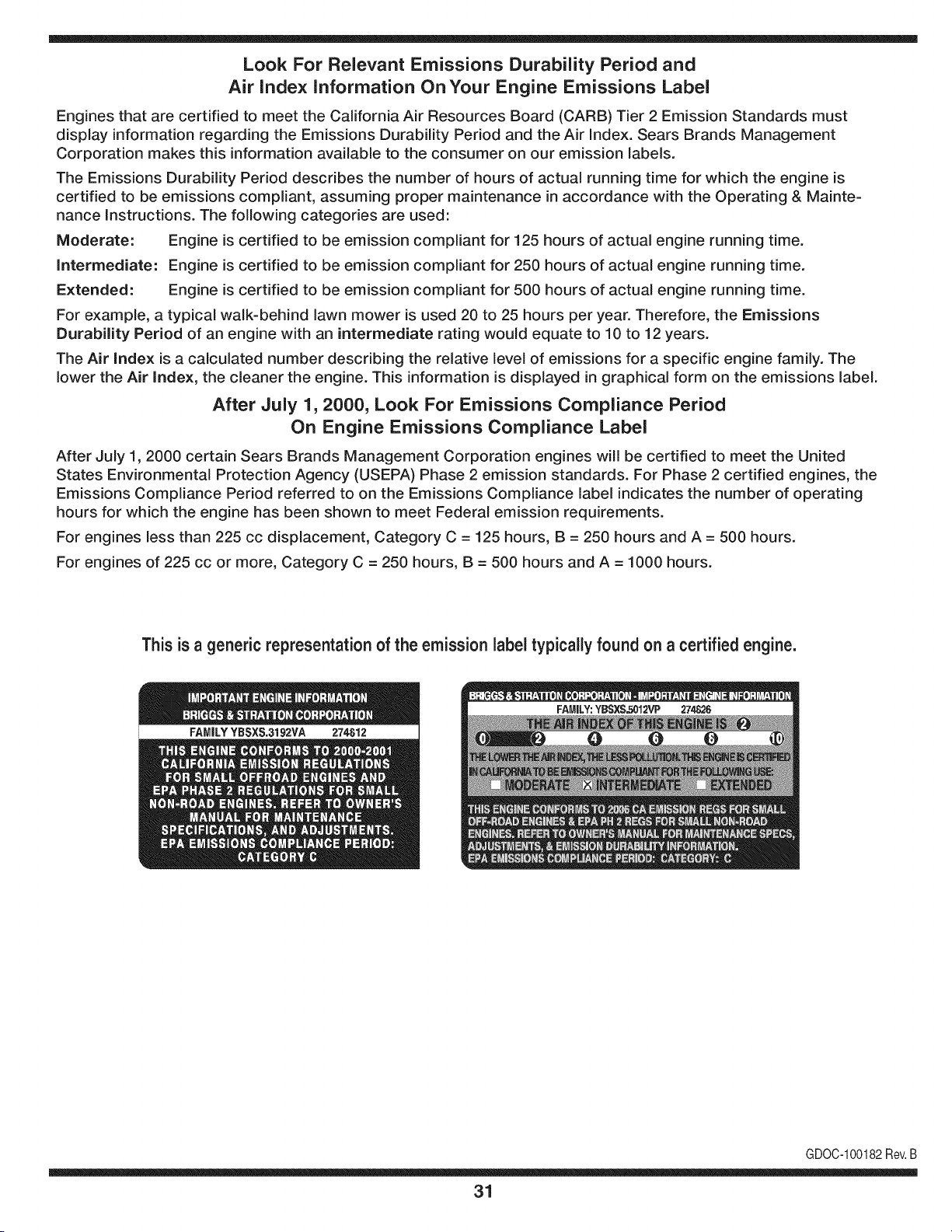
Look For Relevant Emissions Durability Period and
Air index information On Your Engine Emissions Label
Engines that are certified to meet the California Air Resources Board (CARB) Tier 2 Emission Standards must
display information regarding the Emissions Durability Period and the Air Index. Sears Brands Management
Corporation makes this information available to the consumer on our emission labels.
The Emissions Durability Period describes the number of hours of actual running time for which the engine is
certified to be emissions compliant, assuming proper maintenance in accordance with the Operating & Mainte-
nance Instructions. The following categories are used:
Moderate: Engine is certified to be emission compliant for 125 hours of actual engine running time.
Intermediate: Engine is certified to be emission compliant for 250 hours of actual engine running time.
Extended: Engine is certified to be emission compliant for 500 hours of actual engine running time.
For example, a typical walk-behind lawn mower is used 20 to 25 hours per year. Therefore, the Emissions
Durability Period of an engine with an intermediate rating would equate to 10 to 12 years.
The Air index is a calculated number describing the relative level of emissions for a specific engine family. The
lower the Air Index, the cleaner the engine. This information is displayed in graphical form on the emissions label.
After July 1,2000, Look For Emissions Compliance Period
On Engine Emissions Compliance Label
After July 1, 2000 certain Sears Brands Management Corporation engines will be certified to meet the United
States Environmental Protection Agency (USEPA) Phase 2 emission standards. For Phase 2 certified engines, the
Emissions Compliance Period referred to on the Emissions Compliance label indicates the number of operating
hours for which the engine has been shown to meet Federal emission requirements.
For engines less than 225 cc displacement, Category C = 125 hours, B = 250 hours and A = 500 hours.
For engines of 225 cc or more, Category C = 250 hours, B = 500 hours and A = 1000 hours.
This is a generic representation of the emission label typically found on a certified engine.
FAMILYYBSXS.3192VA 274812
GDOC-100182Rev.B
31
(Thispageapplicableinthe U.S.A.and Canadaonly.)
Sears Brands Management Corporation (Sears), the California Air Resources Board (CARD)
and the United States Environmental Protection Agency (U.S. EPA)
Emission Control System Warranty Statement (Owner's Defect Warranty Rights and Obligations)
EMISSIONCONTROLWARRANTYCOVERAGEISAPPLICABLETOCERTI-
FIEDENGINESPURCHASEDIN CALIFORNIAIN 1995ANDTHEREAF-
TER,WHICHARE USEDINCALIFORNIA,ANDTOCERTIFIEDMODEL
California and United States Emission
The CaliforniaAir ResourcesBoard(CARD),U.S.EPAand Searsare pleased
to explainthe EmissionControlSystemWarrantyon your modelyear2000and
latersmalloff-roadengine(SORE).InCalifornia,newsmall off-roadengines
mustbe designed,builtand equippedto meettheState'sstringentanti-smog
standards.Elsewherein the UnitedStates,newnon-road,spark-ignition
enginescertifiedfor modelyear 1997and latermustmeetsimilarstandardsset
forth bythe U.S.EPA.Sears mustwarrantthe emissioncontrol systemon your
YEAR 1997AND LATERENGINESWHICHARE PURCHASEDAND USED
ELSEWHEREIN THEUNITEDSTATES(ANDAFTERJANUARY1,2001 IN
CANADA).
Control Defects Warranty Statement
enginefor theperiodsoftime listedbelow,providedtherehas been noabuse,
neglector impropermaintenanceof your smalloff-roadengine.Youremis-
sion controlsystemincludespartssuch as the carburetor,air cleaner,ignition
system,mufflerand catalyticconverter.Also includedmaybe connectorsand
otheremissionrelatedassemblies.Wherea warrantableconditionexists,Sears
will repairyour smalloff-roadengineat nocostto you includingdiagnosis,parts
and labor.
Sears Emission Control Defects Warranty Coverage
Smalloff-roadenginesarewarrantedrelativeto emissioncontrol partsdefects
fora periodof one year,subjectto provisionsset forth below.Ifany covered
Owner's Warranty
Asthe smalloff-roadengine owner,you are responsiblefor theperformanceof
therequiredmaintenancelistedin yourOperatingand MaintenanceInstruc-
tions.Searsrecommendsthatyou retain allyourreceiptscoveringmaintenance
on yoursmalloff-roadengine,butSears cannotdenywarrantysolelyfor the
lackof receiptsor for yourfailureto ensuretheperformanceof allscheduled
maintenance.As the smalloff-roadengineowner,you shouldhoweverbe
awarethat Searsmay denyyou warrantycoverageif your smalloff-roadengine
ora part hasfailed dueto abuse,neglect,impropermaintenanceor unap-
parton yourengineis defective,the part willbe repairedorreplacedbySears.
Responsibilities
provedmodifications.Youare responsiblefor presentingyour smalloff-road
engineto an AuthorizedSearsServiceDealeras soonas a problemexists.The
undisputedwarrantyrepairsshouldbe completedina reasonableamountof
time,not to exceed30 days.Ifyou haveany questionsregardingyourwarranty
rightsand responsibilities,you shouldcontacta SearsService Representative
at 1-800-469-4663.The emissionwarrantyis a defectswarranty.Defectsare
judgedon normalengineperformance.The warrantyis notrelatedto an in-use
emissiontest.
Sears Emission Control Defects Warranty Provisions
ThefollowingarespecificprovisionsrelativetoyourEmissionControlDefectsWarrantyCoverage.ItisinadditiontotheSearsenginewarrantyfornon-regulated
enginesfound in theOperatingand MaintenanceInstructions.
1. WarrantedParts
Coverageunderthis warrantyextendsonly to the parts listedbelow (the
emissioncontrolsystemsparts)to the extentthese partswere presenton
theengine purchased.
a. FuelMeteringSystem
• Cold start enrichmentsystem
• Carburetorand internalparts
• FuelPump
b. Air lnductionSystem
• Air cleaner
• Intakemanifold
c. IgnitionSystem
• Spark plug(s)
• Magnetoignitionsystem
d. CatalystSystem
• Catalyticconverter
• Exhaustmanifold
• Air injectionsystemor pulsevalve
e. MiscellaneousItemsUsedin AboveSystems
• Vacuum,temperature,position,timesensitivevalves
andswitches
• Connectorsandassemblies
2. Lengthof Coverage
Searswarrantsto the initialownerand eachsubsequentpurchaserthat
theWarrantedPartsshallbe free fromdefects in materialsandworkman-
shipwhich causedthefailure of the WarrantedPartsfor a periodof one
yearfromthe datethe engineis deliveredto a retailpurchaser.
3. NoCharge
Repairor replacementof anyWarrantedPartwill be performedat no
chargeto the owner,includingdiagnosticlabor whichleadsto the
determinationthata WarrantedPartis defective,if the diagnosticwork is
performedat an AuthorizedSearsServiceDealer.Foremissionswarranty
servicecontact yournearestAuthorizedSears ServiceDealeras listed in
the "YellowPages"under"Engines,Gasoline,""GasolineEngines,""Lawn
Mowers,"or similarcategory.
4. Claimsand CoverageExclusions
Warrantyclaimsshall be filed in accordancewiththe provisionsof the
Sears EngineWarrantyPolicy.Warrantycoverageshall be excludedfor
failuresof WarrantedPartswhichare notoriginal Sears partsor because
of abuse, neglector impropermaintenanceas setforth inthe Sears
EngineWarrantyPolicy.Sears is notliableto coverfailuresof Warranted
Partscausedby theuse of add-on,non-original,or modifiedparts.
5. Maintenance
Any WarrantedPart whichis notscheduledfor replacementas required
maintenanceor whichis scheduledonly for regularinspectionto the effect
of "repairor replaceas necessary"shallbe warrantedas to defectsfor the
warrantyperiod.Any WarrantedPartwhich is scheduledfor replacement
as requiredmaintenanceshallbe warrantedas to defectsonly forthe
periodof time up to the first scheduledreplacementfor that part. Any
replacementpart that is equivalentin performanceand durabilitymay
be usedin the performanceof anymaintenanceor repairs.The owneris
responsibleforthe performanceof all requiredmaintenance,as definedin
the SearsOperatingand MaintenanceInstructions.
6. ConsequentialCoverage
Coveragehereundershallextend to thefailure of any enginecomponents
caused bythe failureof any WarrantedPartstill underwarranty.
Inthe USAandCanada,a 24 hour hotline, 1-800-469-4663,has a menuof pre-recordedmessagesofferingyou enginemaintenanceinformation.
GDOC-100188Rev.B
54
FEDERAL and/or CALIFORNIA EMISSION CONTROL WARRANTY STATEMENT
YOUR WARRANTY RIGHTS AND OBLIGATIONS
MTDConsumerGroupInc,the UnitedStatesEnvironmentalProtectionAgency (EPA),and, forthose productscertifiedfor sale in the stateof California,the
CaliforniaAir ResourcesBoard(CARB)are pleasedto explainthe emission(evaporativeand/or exhaust)controlsystem(ECS) warrantyon youroutdoor 2006
andlater smalloff-roadspark-ignitedengine andequipment(outdoorequipmentengine)In California,new outdoorequipmentengines mustbe designed,built and
equippedto meetthe State'sstringentanti-smogstandards (inotherstates, 1997andlater modelyear equipmentmustbe designed,built, and equippedto meet
theU.S. EPAsmalloff-road, sparkignitionengine regulations.MTDConsumerGroupInc mustwarrantthe ECSon your outdoorequipmentenginefor the periodof
timelisted belowprovidedtherehas been no abuse,neglector impropermaintenanceof outdoorequipmentengine.
Your ECSmayincludeparts such as the carburetor,fuel-injectionsystem,the ignitionsystem,catalyticconverter,fuel tanks,fuel lines,fuelcaps, valves,canisters,
filters,vapor hoses,clamps,connectors,andother associatedemission-relatedcomponents.
Wherea warrantableconditionexists, MTDConsumerGroupIncwill repairyouroutdoorequipmentengine at nocost to you includingdiagnosis,partsand labor.
MANUFACTURER'S WARRANTY COVERAGE:
Thisemissioncontrolsystemis warrantedfor two years. If any emission-relatedpart on your outdoorequipmentengine is defective,the part will be repairedor
replacedby MTDCONSUMERGROUPINC.
OWNER'S WARRANTY RESPONSIBILITIES:
Asthe outdoorequipmentengineowner,you are responsiblefor performanceof the requiredmaintenancelisted inyour owner'smanual.MTDConsumerGroup
Inc recommendsthat you retainall receiptscoveringmaintenanceon youroutdoorequipmentengine,but MTDConsumerGroupInc cannotdeny warrantysolely
forthe lackof receipts.
Asthe outdoorequipmentengineowner,you shouldhoweverbe awarethat MTDConsumerGroupInc may denyyou warrantycoverageifyour outdoorequipment
engineor a part has faileddue to abuse, neglect,or impropermaintenanceor unapprovedmodifications.
Youare responsiblefor presentingyouroutdoor equipmentengineto MTDConsumerGroupInc'sdistributioncenteror servicecenteras soon asthe problem
exists.The warrantyrepairsshouldbe completedin a reasonableamountof time, notto exceed30 days.If you havea questionregardingyour warrantycoverage,
you shouldcontactthe MTDConsumerGroupIncService Departmentat 1-800-800-7310orvia emailat http://support.mtdproducts.com
GENERAL EMISSIONS WARRANTY COVERAGE:
MTDConsumerGroupIncwarrantsto the ultimatepurchaserand eachsubsequentpurchaserthat the outdoorequipmentengine is: Designed,built and equipped
so asto conformwithall applicableregulations;and freefromdefects in materialsand workmanshipthatcausethe failureof a warrantedpart to be identicalin all
materialrespectsto that part as describedin MTDConsumerGroup Inc'sapplicationfor certification.
The warrantyperiodbeginson thedate theoutdoor equipmentengine is deliveredto an ultimatepurchaserorfirst placedinto service.The warrantyperiodis two
years.
Subjectto certainconditionsand exclusionsasstated below,the warrantyon emission-relatedparts is asfollows:
1. Any warrantedpart that is not scheduledfor replacementas requiredmaintenancein the written instructionssupplied, is warrantedforthe warrantyperiod
statedabove. Ifthe part fails duringthe periodof warrantycoverage,thepart will be repairedor replacedbyMTDConsumerGroupInc accordingto subsection
(4) below.Anysuchpart repairedor replacedunderwarrantywillbe warrantedfor the remainderof the period.
2. Any warrantedpart that is scheduledonly for regularinspectionin the writteninstructionssupplied is warrantedforthe warrantyperiodstatedabove.Any such
part repairedor replacedunderwarrantywill be warrantedforthe remainingwarrantyperiod.
3. Any warrantedpart that is scheduledfor replacementas requiredmaintenancein the written instructionssuppliedis warrantedfor the periodof time beforethe
first scheduledreplacementdatefor that part. If the partfails beforethefirst scheduledreplacement,the part will be repairedorreplacedby MTDConsumer
GroupInc accordingto subsection(4) below.Any such part repairedor replacedunderwarrantywill be warrantedfor the remainderof the periodprior to the
first scheduledreplacementpointfor the part.
4. Repairor replacementof any warrantedpart underthe warrantyprovisionshereinmustbe performedat a warrantystationat no chargeto the owner.
5. Notwithstandingthe provisionsherein,warrantyservicesor repairswill be providedat allof our distributioncentersthatare franchisedto servicethe subject
enginesor equipment.
6. The outdoorequipmentengineownerwill not be chargedfor diagnosticlaborthat is directlyassociatedwithdiagnosisof a defective,emission-relatedwar-
rantedpart, providedthat suchdiagnosticwork is performedat a warrantystation.
7. MTDConsumerGroup Inc is liablefor damagesto otherengine or equipmentcomponentsproximatelycausedby a failure underwarrantyof any warranted
part.
8. Throughoutthe off-roadengineand equipmentwarrantyperiodstatedabove,MTDConsumerGroupInc will maintaina supplyof warrantedparts sufficientto
meetthe expecteddemandfor such parts.
9. Any replacementpart may be usedinthe performanceof any warrantymaintenanceor repairsand mustbe providedwithoutchargeto the owner.Suchuse will
notreducethe warrantyobligationsof MTDConsumerGroupInc.
10.Add-onor modifiedpartsthat are notexemptedbythe Air ResourcesBoardmaynot beused.The use of any non-exemptedadd-on or modifiedparts by the
ultimatepurchaserwill be groundsfor disallowinga warrantyclaims.MTDConsumerGroup Incwill notbe liable to warrantfailuresof warrantedparts caused
bythe use of a non-exemptedadd-onor modifiedpart.
WARRANTED PARTS:
The repairor replacementof anywarrantedpart otherwiseeligiblefor warrantycoveragemaybe excludedfrom suchwarrantycoverageif MTDConsumerGroup
Inc demonstratesthatthe outdoorequipmentenginehas beenabused,neglected,or improperlymaintained,and that suchabuse, neglect,or impropermainte-
nancewasthe direct causeof the needfor repairor replacementof the part. Thatnotwithstanding,anyadjustmentof a componentthat hasa factory installed,
andproperlyoperating,adjustmentlimitingdevice is still eligible for warrantycoverage.Further,the coverageunderthis warrantyextendsonly to partsthat were
presentonthe off-roadengineand equipmentpurchased.
Thefollowing emissionwarrantypartsare covered(if applicable):
(1) FuelMeteringSystem
• Cold start enrichmentsystem(softchoke)
• Carburetorand internalparts (or fuel injectionsystem)
• Fuelpump
• Fueltank
(2) Air InductionSystem
• Air cleaner
• Intakemanifold
(3) IgnitionSystem
• Spark plug(s)
• Magnetoignitionsystem
(4) ExhaustSystem
• Catalyticconverter
• SAI (Reed valve)
(5) MiscellaneousItemsUsedin AboveSystem
• Vacuum,temperature,position,timesensitivevalvesand switches
• Connectorsandassemblies
(6) EvaporativeControl
• Fuelhose
• Fuelhoseclamps
• Tetheredfuel cap
• Carboncanister
• Vapor lines
GDOC-100223Rev.A

Congratulations on making a smart purchase. Your new Craftsman® product is designed and
manufactured for years of dependable operation. But like all products, it may require repair
from time to time. That's when having a Repair Protection Agreement can save you money and
aggravation.
Here's what the Repair Protection Agreement* includes:
[] Expert service by our 10,000 professional repair specialists
[] Unlimited service and no charge for parts and labor on all covered repairs
[] Product replacement up to $1500 if your covered product can't be fixed
[] Discount of 25% from regular price of service and related installed parts not covered by the
agreement; also, 25% off regular price of preventive maintenance check
[] Fast help by phone - we call it Rapid Resolution - phone support from a Sears representative.
Think of us as a "talking owner's manual."
Once you purchase the Repair Protection Agreement, a simple phone call is all that it takes for you
to schedule service. You can call anytime day or night, or schedule a service appointment online.
The Repair Protection Agreement is a risk-free purchase. If you cancel for any reason during the
product warranty period, we will provide a full refund. Or, a prorated refund anytime after the
product warranty period expires. Purchase your Repair Protection Agreement today!
Some limitations and exclusions apply. For prices and additional information in the U.S.A.
call 1=800=827=6655.
*Coverage in Canada varies on some items. For full details call Sears Canada at 1=800=361=
6665.
Sears Installation Service
For Sears professional installation of home appliances, garage door openers, water heaters, and
other major home items, in the U.S.A. or Canada call 1=800=4=MY=HOME®.
32
Operaci6n segura Practicas .......... Paginas 59 Fuera de temporada de almacenamiento .. Page 85
Etiquetas De Seguridad ................ Page 65 Soluci6n de problemas ................ Page 86
Asamblea ........................... Page 66 Lista de piezas ..................... Paginas 30
Operacion de ...................... Paginas 68 Reparaci6n de Acuerdo de Protecci6n .... Page 91
De Servicio y Mantenimiento de ....... Paginas 75 Servicio de nOmeros ............ atrasados Page
CRAFTSMAN GARANT{A TOTAL
PORDOSANOSa partirde lafechade cornpra,todaslaspartesno fungiblesdeesteequipodeequitaci6nest_ngarantizadoscontracualquierdefectode
materialo rnanode obra.UnapiezadefectuosanofungiblesredbirAnreparaci6ngratuitaenelhogaro iasustituci6nsi iareparaci6nes irnposible.
Durantecincoa_osdesdelafechadecornpra,elejedelmarcoy elfrentedeesteequipodeequitaci6nest_ngarantizadoscontracualquierdefectode
materialo rnanode obra.Uncuadrodefectuosooejedelanterorecibir_reparacbngratuitaenel hogaro lasustitucbnsilareparacbnesirnposible.
POR90 D{ASa partirdelafechadecornpra,labateria(unapartefungibles)deesteequipodeequitaci6nest_garantizadacontracualquierdefectode
materialo rnanode obra(nuestraspruebasdernuestraqueno rnantienela carga).Unabateriadefectuosarecibir_reernplazogratuitoen elhogar.
ADIOiONALDEGARANT{ALIMiTADADEPORViDAen FUNDiCiONejedelantero(si est;_instalado)
PARASIEMPREY COMOSEUTILIZAporelpropietariooriginaldespu_sdelquintoa_odesdela fechadecornpra,elhierrofundidoejedelantero(siexiste)
deesteequipodeequitacbnest_garantizadacontracualquierdefectodematerialornanode obra.Conelcornprobantedecornpra,unejedelanterofundido
defectuosorecibirAreernplazogratuitoenelhogar.
GARANT{ADESERViCiO
Paraobtenerinforrnaci6ndetalladacoberturade iagarantiaparaobtenerlareparaci6no sustituci6ngratuita,Ilarneal1-800-659-5917ovisiteel sitioweb:
www.craftsrnan.corn
Entodosloscasosanteriores,si lareparaci6no reernplazodeunapartees irnposible,elequipodeequitaci6nser_.reernplazadodeformagratuitaconel
rnisrnoo equivalente.
Todoslosdelacoberturade lagarantiaanteriores inv&lidasiesteequipode rnontara caballoesutilizadoalgunavez,rnientrasquelaprestacbnde servicios
cornercialeso sisealquilaaotrapersona.
Estagarantiacubrelos defectosSOLOde materialesyfabricacibn.Lagarantianoincluye:
• Laspartesconsurnibles(exceptola bateria)quepuedegastarseporel usonormaldentrodel periododegarantia,incluyendoperonolirnitadoa,cuchillas,
bujias,fiitrosde aire,correasy fiitrosdeaceite.
• Losserviciosdemantenimiento,cambiosdeaceite,o puestasa punto.
• Tireelreernplazoo reparacbnde pinchazoscausadospotobjetosexternos,talescornoclavos,espinas,toconeso vidrio.
• Tiredela ruedao elreernplazoo lareparaci6nresultantesdeldesgastenormal,accidenteornalfuncionarnientoo rnantenirniento.
• Lasreparacionesnecesariasdebidoal abusodeloperador,incluyendoperonolirnitadoa losdaSoscausadosporelrernolquedelosobjetosrn&sall&de la
capacidaddelequipodeequitaci6n,elirnpactodeobjetosquedoblenla estructura,elrnontajedelejeo delcig(JeSal,o deexcesodeveiocidaddelmotor.
• Lasreparacionesnecesariasdebidoa lanegligenciadeloperador,incluyendoperonolirnitadoa,daSoselectricosy rnecanicoscausadosporunalrnace-
narnientoinadecuado,noutilizaci6ndelacalidado cantidaddeaceitede motor,nornantenerel pisolibrederesiduosinflarnables,ofaltadernantenirniento
delEquipoecuestredeacuerdoalas instruccionescontenidasenelmanualdeloperador.
• Elmotor(sisternade combustible)delirnpiezao reparacionesprovocadasporuncombustiblequesecontarninadouoxidado(viejo).Engeneral,el
combustibledebeserutilizadodentrodelos30diassiguientesalafechadecornpra.
• deterioroy desgastenormalde losacabadosexteriores,o reernplazodelaetiquetadelproducto.
Estagarantiale otorgaderechoslegalesespecificos,y ustedtarnbi6npuedetenerotrosderechosquevariandeestadoa estado.
SearsBrandsManagementCorporation,HoffmanEstates,iL60179
Aceitedel motor: SAE30
Combustible: Gasoiinasinplorno
Bujia: Champion®RC12YC
Motor: Briggs& Stratton
N_mero de modelo ..........................................................
N_mero de serie ..............................................................
Fechade compra .............................................................
RegistrearribaelnQmerodelmodelo,elnQmerodeserieylafechadecompra
© SearsBrands,LLC
58
Lapresenciadeeste sirnboloindicaque setratade instrucciones
irnportantesde seguridadquese debenrespetarparaevitar
poneren peligrosu seguridadpersonaly/o materialy lade otras
personas.Leay siga todaslas instruccionesde estemanualantes
de poneren funcionarnientoestarn_.quina.Si no respetaestas
instruccionespodriaprovocarlesionespersonales.Cuandoveaeste
sirnbolo,ipresteatenci6na la advertencia!
PROPOSICION 65 DE CALIFORNIA
Elescapedel motordeesteproducto,algunosde suscornponentes
y algunoscornponentesdel vehiculocontieneno liberan sustancias
quirnicasqueel estadode Californiaconsideraque puedenproducir
c_.ncer,defectosde nacirnientouotrosproblernasreproductivos.
Losbornesdela bateriay los accesoriosalinescontienenplornoy
cornpuestosde plorno,sustanciasquirnicasque segOnIo estableci-
do pot el Estadode Californiacausanc_.ncery da_osenel sisterna
reproductivo.Ldveselas manos despu_sde estaren contacto
con estoscomponentes.
Estarn_.quinarueconstruidapara seroperadadeacuerdocon
las reglasde seguridadcontenidasenestemanual.AI igualque
concualquiertipo deequipo rnotorizado,undescuidoo errorpor
partedeloperadorpuedeproducirlesionesgraves.Esta rn_.quina
es capazde arnputarrnanosy piesy dearrojarobjetoscon gran
fuerza.Deno respetarlas instruccionesde seguridadsiguientesse
puedenproducirlesionesgraveso larnuerte.
Su responsabilidad--Restrinja el usode estarn_.quina
rnotorizadaalas personasque lean,cornprendany respetenlas
advertenciase instruccionesqueaparecenen este manualyen la
rn_.quina.
iGUARDEESTASINSTRUCCIONES!
FUNCIONAMIENTO GENERAL
• Lea,entienday curnplatodaslas instruccionesincluidasen
la rn_.quinayen los rnanualesantesde rnontarlay utilizarla.
Guardeestemanualenun lugarseguroparaconsultasfuturasy
peri6dicas,asi cornoparasolicitarrepuestos.
• Farniliaricesecontodos los controlesy con el usoadecuado
delos rnisrnos.Sepa c6rnodetenerla rn_.quinay desactivarlos
controlesr_.pidarnente.
• No perrnitanuncaque los ni_osrnenoresde 14a_osutilicen
estarn_.quina.Los ni_osde 14a_osen adelantedeben leery
entenderlas instruccionesde operaci6ny norrnasde seguridad
contenidaseneste manual,y en la rn_.quinay debenser
entrenadosy supervisadospor unadulto.
• Nuncaperrnitaque los adultosoperenestarn_.quinasin recibir
antesla instrucci6napropiada.
• Paraayudaraevitarel contactocon las cuchillaso unalesi6npor
algOnobjetoquesea arrojado,rnantengaa los observadores,a
los ayudantes,ni_osy rnascotasalejadosal rnenos25 metrosde
la rn_.quinarnientrasest,.en funcionarniento.Detengala rn_.quina
si alguienentraen la zona.
• Inspeccionerninuciosarnenteel Areadondeutilizar_,el equipo.
Retiretodaslas piedras,palos,cables,huesos,juguetesy otros
objetosextra_osquepodrianser recogidosy arrojadospor la
acci6nde las cuchillas.Losobjetosarrojadospor la rn_.quina
puedenproducirlesionesgraves.
• Planifiqueel patr6nde cortedel c_spedque ha de seguirpara
evitarla descargade materialhacialoscarninos,las veredas,los
observadores,etc.Eviteadern_.sdescargarmaterialcontralas
paredesy obstruccionesquepodrianprovocarqueel material
descargadorebotecontrael operador.
• Paraprotegerselos ojos utilicesiernpreanteojoso antiparras
deseguridadrnientrasoperala rn_.quinao rnientraslaajusta
o repara.Losobjetosarrojadosque rebotanpuedenproducir
lesionesocularesgraves.
• Utilicezapatosde trabajoresistentes,desuelafuerte,asi corno
pantalonesy carnisasajustados.Las prendassueltaso las
alhajaspuedenquedaratrapadasen las piezasrnovibles.Nunca
operela rn_.quinadescalzoo con sandalias.
• Est_atentoa la cortadoray a la direcci6nde la descargade
losaditarnentosy no apuntea nadie.Nuncaoperelacortadora
de c_spedsin que est_nen su lugarapropiadola cubiertade
descargao elcolectorde recortesdecesped.
• Noponga lasrnanoso lospies cercade las piezasrotatoriaso
debajode la plataforrnadecorte. Elcontactocon las cuchillas
puedeproducirla arnputaci6ndernanosy pies.
• Unacubiertade descargafaltanteo da_adapuedeprovocarel
contactocon lacuchillao lesionespot objetosarrojados.
• Detengala(s)cuchilla(s)cuandoatraviesesenderos,sendaso
carninosde gravay cuandonoest_cortandoel cesped.
• Vigileel tr_.nsitovehicularcuandoest_operandocercade o en
crucesde carninos.Estarn_.quinanodebeutilizarseen la via
pOblica.
• Noopereestarn_.quinabajolosefectosdelalcoholode drogas.
• Corteel cespedsolarnentecon luzdedia o conunabuenaluz
artificial.
• Nuncatransportepasajeros.
• Desenganchela(s)cuchilla(s)antesdecolocarlarnarchaatr_.s.
Retrocedalentarnente.Siernpremirehaciaabajoy haciaatr_.santes
y rnientrasretrocede,paraevitaraccidentes.
• Reduzcala velocidadantesdedarlavuelta.Operela rn_.quina
suavernente.Evitelaoperaci6nerr_.ticay la velocidadexcesiva.
• Desenganchela(s)cuchilla(s),coloqueelfrenode estaciona-
rniento,detengaelmotory esperehastaquela(s)cuchilla(s)se
detenga(n)porcornpletoantesderetirarel colectordec_sped,
vaciarlos recortes,destaparelcanal,retirarrestosde cespedo
desechos,o hacercualquierajuste.
59
• Nuncadejela rn_.quinaen funcionarnientosinvigilancia.Apague
siernprelascuchillas,coloqueel frenodernano,detengael motory
retirela Ilaveantesdebajarsedel vehiculo.
• Tengasurnocuidadoalcargaro descargarlarn_.quinaen un
rernolqueocarni6n.Estaunidadnodebeconducirseen ascensoo
descensoderarnpas,porquepodrialadearsey provocarlesiones
personalesgraves.Enlas rarnpaslarn_.quinasedebeernpujar
rnanualrnenteparacargarlao descargarlacorrectarnente.
• Elsilenciadory el motorse calientany puedencausarquernaduras.
Nolos toque.
• Reviseel espaciolibrepot encirnade lacabezaantesdeconducir
bajolas rarnasbajasde_.rboles,cables,cerrarnientosde puertas,
etc.enloscualeseloperadorpodriaatorarseo serernpujadofuera
dela rn_.quina,Ioquepodriaresultaren lesionesgraves.
• Desenganchetodoslosernbraguesde los accesoriosy presione
totalrnenteel pedaldelfrenoantesdeintentararrancarel motor.
• Larn_.quinaest,.diseSadaparacortarc_spedresidencialnormal,
conunaalturano mayora 10".Nointentecortarcespeddernasiado
crecido,seco(porej.,pastura)nipilasde hojassecas.Elc_sped
y las hojassecaspuedenentraren contactoconel escapedel
motory/o acurnularseenla plataforrnade lacortadoradecesped,
convirti_ndoseen un peligrode incendio
• Utilicesolarnenteaccesoriosy aditarnentosaprobadosparaesta
rn_.quinapot elfabricantedela rnisrna.Lea,cornprenday siga
todaslasinstruccionesproporcionadasconlosaccesorioso
aditarnentosaprobados.Paraobtenerunalistade losaccesorios
aprobadosy losarchivosadjuntos,Ilarne1-800-659-5917.
• Losdatosestadsticosrnuestranque losoperadoresde60 aSos
y rnayoresseven involucradosen unaltoporcentajede lesiones
relacionadascontractorescorta cesped.Estosoperadoresdeben
evaluarsu capacidadparaoperarel tractorcortac_spedenforrna
suficienternentesegurapara protegersea ellosrnisrnosy a los
dern_.scontralesionesgraves.
Si se presentansituacionesqueno est_.nprevistasen este
manualsea cuidadosoy use el sentidocornQn.Contacto1-800-
659-5917parainforrnaci6ny asistencia.
FUNCIONAiVIIENTO EN PENDIENTES
Las pendientesson unfactorirnportanterelacionadoconaccidentes
porderrapey vuelcosquepuedenproducirlesionesgravese incluso
la rnuerte.La operaci6nen pendientesrequieremayorprecauci6n.
Si nopuederetrocederen la pendienteo si no se sienteseguro,no
realiceningunaoperaci6nde corte.
Parasu seguridad,use el indicadordependientesquese incluye
cornopartede estemanualpara rnedirla pendienteantesde operarla
rn_.quinaenuna zonainclinada.Sila pendientees mayorde 15 grados
segQnel rnedidor,no opereestarn_.quinaen ese sector,puespodria
causarlesionesgraves.
HagaIo siguiente:
• Podehaciaarribay abajodelas pendientes,no deforrnatrans-
versal.Tengacuidadocuandocarnbiededirecci6nal operaren
pendiente.
• Est_atentoa loshoyos,surcos,baches,rocas,uotrosobjetos
ocultos.El terrenodesniveladopuedevoltearla rn_.quina.El cesped
altopuedeocultarobst_.culos.
Vayaa bajavelocidad.ElijaunavelocidadIosuficienternentebaja,
de rnodoque notengaquedetenerseohacercarnbiosrnientras
est,.sobrela pendiente.Losneurn_.ticospodrianperdertracci6n
sobrelaspendientesaQncuandolosfrenosfuncionaranapro-
piadarnente.Siernprernantengala rn_.quinaen carnbiornientras
desciendelaspendientes,parapoderfrenarconel motor.
• Sigalas recornendacionesdelfabricanteparalos pesoso contra-
pesosdelas ruedas,pararnejorarla estabilidadde larn_.quina.
Pararecornendaciones,Ilarneal 1-800-659-5917.
• Tengaespecialcuidadocon loscolectoresde cespeduotros
aditarnentos.Losrnisrnospuedenrnodificarlaestabilidadde la
rn_.quina.
• Hagaquetodoslos rnovirnientosen laspendientesseanlentosy
graduales.Nocarnbierepentinarnentelavelocidadniladirecci6n.
Unfrenadoo carnbiodevelocidadrepentinospuedencausarque
el frentede la rn_.quinase levantey d_unavolteretahaciaatr_.s,Io
quepodriaproducirlesionesgraves.
• Evitearrancaro detenerseen unapendiente.Silosneurn_.ticos
pierdenlatracci6n,desenganchelascuchillasy descienda
lentarnentela pendiente.
No hagaIo siguiente:
• Nogiresobrelas pendientesa rnenosqueseanecesario.Sies
posible,girelentarnentey gradualrnenteduranteel descenso.
• Nocorteelc_spedcercade pozos,hundirnientosoterraplenes.La
cortadoradec_spedpuedevolcarserepentinarnentesiunade las
ruedasest,.sobreelhordede unacantilado,zanjao siun hordese
desrnorona.
• Nointenteestabilizarla rn_.quinaponiendoelpie enel suelo.
• Noutiliceuncolectorde cespeden pendientesernpinadas.
• Nopodeelcespedh_rnedo.Unarnenortracci6npodriacausar
derrapes.
• Noparadescender.Elexcesodevelocidadpuedehacerqueel
operadorpierdael controldela rn_.quina,ocasionandolesiones
graveseinclusolarnuerte.
• Norernolquecargaspesadasdetr_.sde losaditarnentos(carritode
basuracargado,podadoraderodillos,etc)en pendientesrnayores
de5 grados.Cuandosedesplazapendienteabajo,el pesoadicional
tiendeaernpujarel tractory puedehacerquese pierdaelcontrol
delrnisrno(porejernplo,eltractorsepuedeacelerar,se reducela
capacidadparafrenary rnaniobrar,losaccesoriospuedenplegarse
cornouncortaplurnasy hacerqueeltractorvuelque).
NINOS
Puedenocurriraccidentestr_.gicossi el operadornoest,. atentoa la
presenciade niSos.PotIo general,los niSosse sientenatraidospor
estetipo de rn_.quinasy su funcionarniento.Noentiendenlos riesgos
ni los peligros.Nuncaasurnaque los niSosperrnanecer_.nen el rnisrno
lugardonde losvio pot Qltirnavez.
• Mantengaa losniSosfueradel_.readetrabajoy bajoestricta
vigilanciadeunadultoresponsableadern_.sdel propiooperador.
Est_alertay apaguela rn_.quinasiunniSoingresaal _.rea.
• Antesy rnientrasest,.retrocediendo,mirehaciaatr_.sy cuidequeno
hayaniSos.
NuncatransporteniSos,aQnconla cuchillaapagada.Podriancaerse
y resultarseverarnenteheridoso interferirconlaoperaci6nsegurade
la rn_.quina.
Tengaextrernaprecauci6ncuandoseaproxirneaesquinasciegas,
portales,arbustos,_.rbolesuotrosobjetosquepuedanirnpedirlever
a unniSoquesecruceenel recorridode larn_.quina.
6O
• Paraevitaraccidentesaloperarenrnarchaatr_.s,siernpredesengan-
chelascuchillasantesdecolocarrnarchaatr_.s.Siest,.instalado,
el"ModoPrecaucidnMarchaAtr_.s"(hojasde operarla rn_.quina,
rnientrasquelospaseosala inversa)nodebeutilizarsecuandohay
ni_osuotraspersonaspresentes.
• Mantengaa losni_osalejadosdelosrnotoresenrnarchao calientes.
Puedensufrirquernadurasconunsilenciadorcaliente.
• RetirelaIlavecuandodeje larn_.quinasinvigilancia,evitequeuna
personasinautorizaci6nlarnaneje.
No perrnitanuncaque los ni_osrnenoresde 14a_osutilicenesta
rn_.quina.Losni_osde 14a_osen adelantedeben leery entenderlas
instruccionesdeoperaci6ny norrnasde seguridadcontenidasen este
manual,y en la rn_.quinay deben serentrenadosy supervisadospor
unadulto.
REIVIOLQUE
• Rernolque_nicarnenteconunarn_.quinaquecuenteconun
enganchediseSadopararernolcar.Noacopleequiporernolcado
exceptoen elpuntode enganche.
• Sigalasrecornendacionesdel fabricanteen Ioquerespectaalos
lirnitesdepesodelosequiposa rernolcary alrernolqueenpendien-
tes.Pararecornendaciones,Ilarneal 1-800-659-5917.
• Nuncaperrnitala presenciade niSosuotraspersonasdentroosobre
losequiposrernolcados.
• Enlaspendientes,elpesodel equiporernolcadopuedecausar
p_rdidadetraccidny perdidade controlde la rn_.quina.
• Siernpreuseextrala precauci6nrernolcandoconunarn_.quina
capazde hacervueltasapretadas(p.ejpaseo"devueltacero"- enel
cortacesped).Hagaarnpliasvueltasparaevitaralgato-knifing.
• Despl_.ceselentarnentey dejedistanciaadicionalparafrenado.
• Noparadescender.
SERVIClO
Manejo seguro de la gasolina
Paraevitarlesionespersonaleso daSosrnaterialessea surnarnente
cuidadosoal rnanipularla gasolina.La gasolinaes surnarnente
infiarnabley susvaporespuedencausarexplosiones.Se puede
lesionargravernentesi derrarnagasolinasobreustedo sobrela ropa,
ya que_stase puedeincendiar.L_.vesela piely c_.rnbiesede ropade
inrnediato.
• Utilices61olos recipientesparagasolinaautorizados.
• NuncaIlenelos recipientesenel interiorde unvehiculoo carnidn
o cajade rernolquecon recubrirnientopl_.stico.Coloquesiernpre
los recipientesenel piso y lejosdel vehiculoantesde realizarla
carga.
• Cuandoseafactible, retireel equipoa gasolinadel carni6no
rernolquey II_neloen elsuelo. Siesto noes posible,Ileneel
equipoen unrernolqueconun contenedorport_.til,envezde
hacerlocon unaboquilladispensadoradegasolina.
• Mantengala boquillade Ilenadoen contactoconel hordedel
dep6sitode combustibleocon la aberturadel recipienteen todo
rnornento,hastaterrninarlacarga.No utiliceundispositivode
boquilladeapertura/cierre.
• Apaguetodosloscigarrillos,cigarros,pipasy otrasfuentesde
cornbustidn.
• Nuncacarguecombustibleenla rn_.quinaen un espaciocerrado.
• Nuncasaquela tapadel combustibleni agreguecombustible
rnientrasel motorest,.calienteo en rnarcha.Dejequeel motor
seenfrie porIornenosdos rninutosantesde volvera cargar
combustible.
• NuncaIleneen excesoel dep6sitode combustible.Lleneel
tanquenorn_.sde 1/2pulgadapor debajode labasedel cuello
del tap6ndecarga, paradejarespaciopara laexpansi6ndel
combustible.
• Vuelvaa colocar latapa dela gasolinay ajQstelabien.
• Lirnpieel combustiblequese hayaderrarnadosobreel motory el
equipo.Trasladela rn_.quinaa otrazona.Espere5 rninutosantes
de encenderelmotor.
• Parareducirel riesgode incendio,rnantengala rn_.quinalirnpia
de pasto,hojasy deacurnulacidnde otros residuos.Lirnpielos
derrarnesdeaceiteo combustibley saquetodoslos residuos
ernbebidosde combustible.
• Nuncaguardelarn_.quinao el recipientedecombustibleen un
espaciocerradodondehayafuego,chispaso luz piloto,corno
porejernplodecalentadoresdeagua,calefactoresde arnbientes,
hornos,secadoresde ropau otrosaparatosa gas.
• Dejeque larn_.quinase enfriecincorninutospor Iornenosantes
de guardarla.
Servicio general
• Nuncaenciendael motoren espacioscerradoso en unazona
con pocaventilacidn.Elescapedel motorcontienernondxidode
carbono,ungas inodoroy letal.
• Antesdelirnpiar,repararo inspeccionarla rn_.quina,cornpruebe
que la(s)cuchilla(s)y todaslas partesenrnovirnientose hayan
detenido.Desconecteel cablede la bujfay p6ngalohaciendo
rnasacontrael motorparaevitarquese enciendaaccidental-
rnente.
• Reviseperi6dicarnenteparaasegurarsequelas cuchillasse
detenganporcornpletoenaproxirnadarnentecinco(5) segundos
despu_sdeaccionarel controlde desenganchede la(s)
cuchilla(s).Si las cuchillasno se detienendentrodeeste lapso
de tiernpo,su unidaddeber_,ser reparadaporsu distribuidorde
servicioautorizadoMTD.
• Reviseconfrecuenciaelfuncionarnientodel sisternadefrenos
ya queest,.sujetoa desgastepor la operaci6nnormal.Ajustey
efectQernantenirnientosegQnse requiera.
61
• Reviselos pernosdemontajede la(s) cuchilla(s)y del motora
intervalosfrecuentesparaverificarque est_nbien apretados.
Adem_.s,inspeccionevisualmentela(s) cuchilla(s)en buscade
daSos(porejemplo,desgasteexcesivo,abolladuras,rajaduras,
etc.). Reemplacela(s) cuchilla(s)Qnicamentecon lascuchillas
defabricantesde equiposoriginales(O.E.M.)listadasen este
manual.Elusode piezasqueno cumplencon las especifi-
cacionesdelequipooriginalpodriatenercomoresultadoun
rendimientoincorrectoy adem_.sponeren riesgola seguridad.
• Lascuchillasdelas podadorassonmuy afiladas.Envuelvala
cuchillao utiliceguantesy extremelasprecaucionescuando
efectQemantenimiento.
Mantengatodoslos pernos,tuercasy tornillosbienajustados
paraasegurarsede que la m_.quinase encuentraen condiciones
segurasde operaci6n.
• Nuncaaltereel sistemade enclavamientode seguridadni
otrosmecanismosde seguridad.Controleperiddicamenteque
funcionencorrectamente.
Despu_sdegolpearcon algQnobjetoextraSo,detengael motor,
desconecteel cablede la bujfay conecteel motora masa.
Inspeccioneminuciosamentela m_.quinaparaver si est,. daSada.
Repareel daSoantesde arrancary ufilizarla m_.quina.
Nuncatratede hacerajusteso reparacionesa la m&quina
mientrasel motorest&enmarcha.
• Loscomponentesdel colectorde c_spedy la cubiertade
descarga,estansujetosa desgastey daSosque podriandejar
expuestaspartesen movimientoo permitirque se arrojenobjetos.
Paraprotegersuseguridad,verifiquefrecuentementetodos los
componentesy reempl_.celosinmediatamentes61ocon piezasde
los fabricantesdel equipooriginal,listadosen estemanual.El uso
de piezasque no cumplencon las especificacionesdel equipo
originalpodriatenercomoresultadoun rendimientoincorrectoy
adem_.sponeren riesgola seguridad.
• Nocambielaconfiguraci6ndel reguladordel motorni Ioopere
a sobrevelocidad.El reguladordel motorcontrolala velocidad
m_.ximasegurade funcionamientodel motor.
• Mantengao reemplacelasefiquetasde seguridade instrucciones
segQnseanecesario.
Respetelas normasreferentesa ladisposicidncorrectay las
reglamentacionessobregasolina,aceite,etc. paraprotegerel
medicambiente.
• SegQnla Comisi6nde Seguridadde Productospara el Consu-
midorde los EstadosUnidos(CPSC)y laAgenciade Proteccidn
Ambientalde los EstadosUnidos(EPA),este productotieneuna
vida Qtilmediade siete(7) aSos,6 270horasde funcionamiento.
AIfinalizarla vidaOtilmedia,adquieraunam_.quinanuevao haga
inspeccionaranualmente_staSearsporunou otrodistribuidorde
serviciosparacerciorarsedequetodoslos sistemasmec_.nicos
y de seguridadfuncionancorrectamentey no tienenexcesivo
desgaste.Si no Io hace,puedenproducirseaccidentes,lesiones
o muerte.
NO MODIFIQUE EL MOTOR
Paraevitarlesionesgraveso lamuerte,no modifiqueel motorbajo
ningunacircunstancia.Si cambialaconfiguraci6ndel reguladordel
motorel motorpuededescontrolarsey operara velocidadesinsegu-
ras.Nuncacambielaconfiguraci6ndef_.bricadel reguladordel motor.
AVlSO REFERIDO A EMISIONES
Losmotoresqueest_.ncertificadosy cumplencon las regulaciones
de emisionesfederalesEPAy de CaliforniaparaSORE(Equipos
peque_ostodoterreno)est_.ncertificadosparaoperarcongasolina
comQnsin plomoy puedenincluirlos siguientessistemasde control
de emisiones:Modificaci6nde motor(EM) y catalizadorde tresvias
(TWO)siest_.nequipadosde esa manera.
GUARDACHISPAS
EstamAquinaest,.equipadacon un motorde combusti6ninternay
nodebe ser utilizadaen o cercade unterrenoagrestecubiertopor
bosque,malezaso hierbaexceptosi el sistemade escapedel motor
est,.equipadocon unamortiguadordechispasque cumplacon las
leyeslocaleso estatalescorrespondientes,encasode haberlas.
Si se utilizaunamortiguadorde chispasel operadorIo debemantener
en condicionesde usoadecuadas.Enel Estadode Californialas
medidasanteriormentemencionadassonexigidaspor Icy (Arficulo
4442del C6digode RecursosPOblicosde California).Esposible
queexistanleyessimilaresenotrosestados.Lasleyesfederalesse
aplicanenterritoriosfederales.
Puedeconseguirel amortiguadorde chispasparael silenciadora
travesdesu distribuidorautorizadode motoreso poni_ndoseen
contactoconel centrode servicioSears.
62
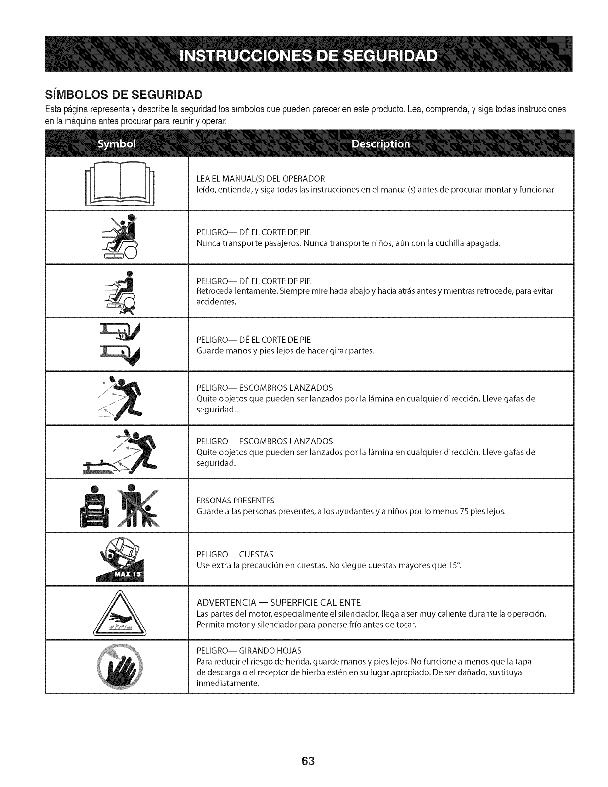
SJlVlBOLOS DE SEGURIDAD
Estap&ginarepresentay describelaseguridadlos simbolosquepuedenpareceren este producto.Lea,comprenda,y sigatodasinstrucciones
enla m_quinaantesprocurarparareuniry operar.
0
AL
LEA EL MANUAL(S) DEL OPERADOR
leido, entienda, y siga todas las instrucciones en el manual(s) antes de procurar montar y funcionar
PELIGRO-- DE EL CORTE DE PIE
Nunca transporte pasajeros. Nunca transporte ni_os, aun con la cuchilla apagada.
PELIGRO-- DE EL CORTE DE PIE
Retroceda lentamente. Siempre mire hacia abajo y hacia atr_is antes y mientras retrocede, para evitar
accidentes.
PELIGRO-- DE EL CORTE DE PIE
Guarde manos y pies lejos de hacer girar partes.
PELIGRO-- ESCOMBROS LANZADOS
Quite objetos que pueden ser lanzados pot la I_imina en cualquier direcci6n. Lleve gafas de
seguridad..
PELIGRO-- ESCOMBROS LANZADOS
Quite objetos que pueden ser lanzados pot la I_imina en cualquier direcci6n. Lleve gafas de
seguridad.
ERSONAS PRESENTES
Guarde alas personas presentes, a los ayudantes y a ni_os pot Io menos 75 pies lejos.
PELIGRO-- CUESTAS
Use extra la precauci6n en cuestas. No siegue cuestas mayores que 15°.
ADVERTENCIA -- SUPERFICIE CALIENTE
Las partes del motor, especialmente el silenciador, Ilega a set muy caliente durante la operaci6n.
Permita motor y silenciador para ponerse frio antes de tocar.
PELIGRO-- GIRANDO HOJAS
Para reducir el riesgo de herida, guarde manos y pies lejos. No funcione a menos que la tapa
de descarga o el receptor de hierba est_n en su lugar apropiado. De ser dahado, sustituya
inmediatamente.
63
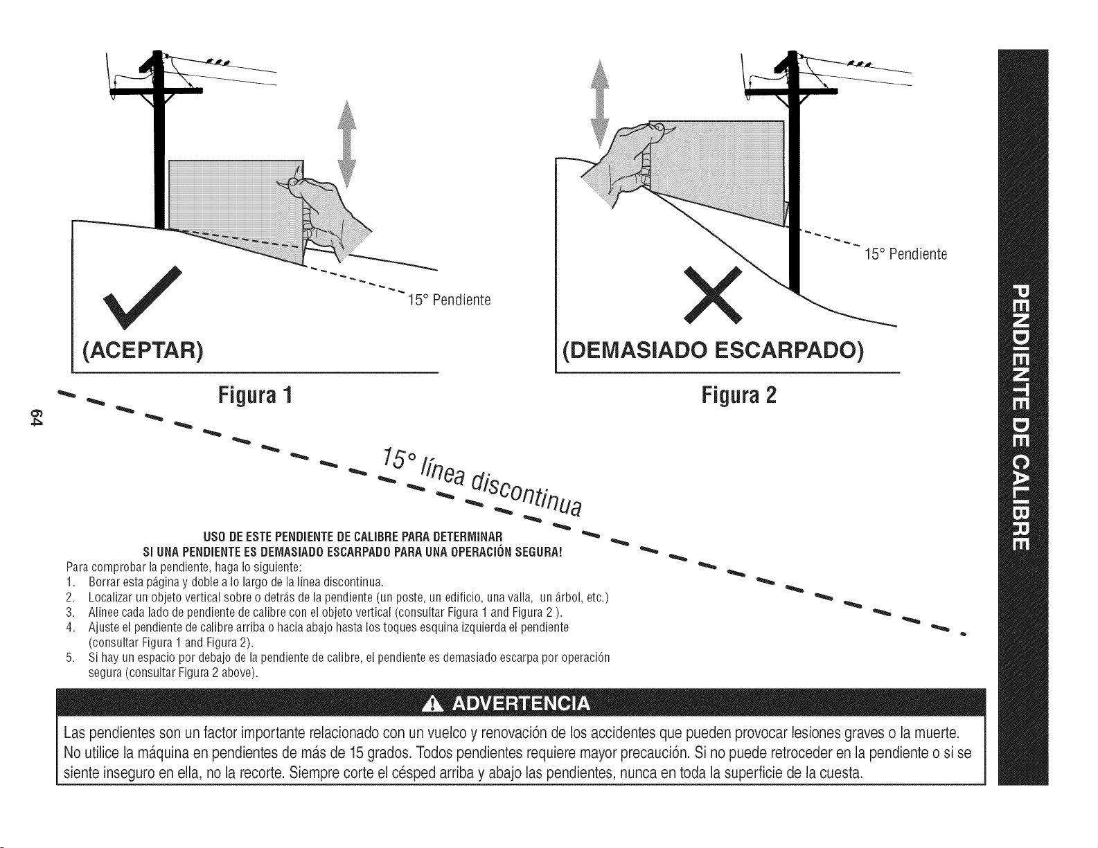
(ACEPTAR)
I5 ° Pendiente
X
(DEMASIADO ESCARPADO)
15° Pendiente
4_
• Figura1
"'"
USO DE ESTE PENDiENTE DE CALIBRE PARA DETERrvIINAR
SlUNA PENDIENTE ES DEIVlASIADOESCARPADO PARA UNA OPEBACION SEGURA!
Para comprobar la pendiente, haga Io siguiente:
1. Borrar esta p_ginay doble a Io largo de la linea discontinua.
2.
3.
4.
5,
Localizar un objeto vertical sobre o detr_.sde la pendiente (un poste, un edificio, una valla, un _.rbol,etc.)
Alinee cada lado de pendiente de calibre con el objeto vertical (consultar Figura 1 and Figura 2 ).
Ajuste el pendiente de calibre arriba o hacia abajo hasta los toques esquina izquierda el pendiente
(consultar Figura 1 and Figura 2).
Si hay un espacio por debajo de la pendiente de calibre, el pendiente es demasiado escarpa por operaci6n
segura (consultar Figura 2 above).
Figura 2
Las pendientes son un factor importante relacionado con un vuelco y renovaci6nde los accidentes que pueden provocar lesiones graves o la muerte.
No utilice la ma.quinaen pendientesde ma.sde 15 grados. Todospendientes requiere mayor precauci6n. Si no puede retroceder en la pendiente o si se
siente inseguro en ella, no la recorte. Siemprecorte el cesped arriba y abajo las pendientes, nunca en toda la superficie de la cuesta.
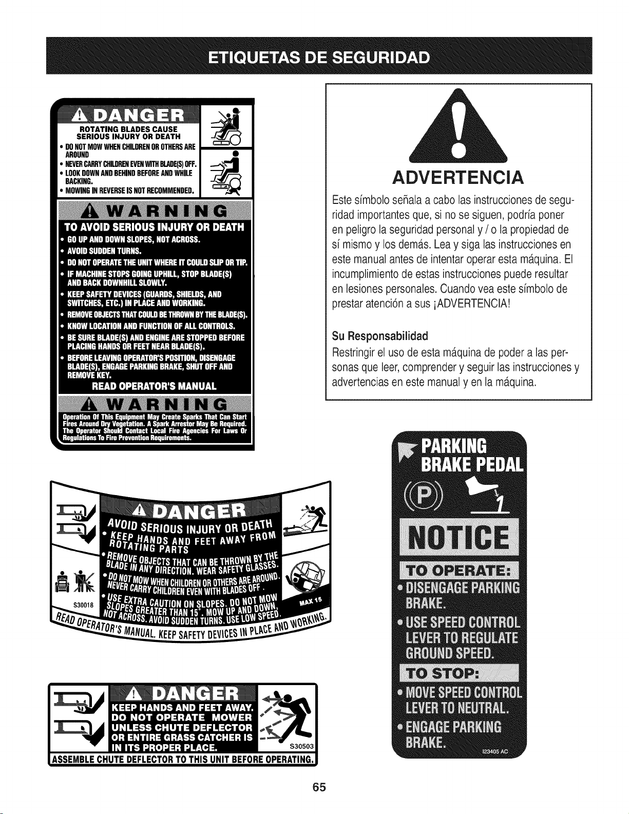
ROTATING BLADES CAUSE
SERIOUS INJURY OR DEATH
DONOTMOWWHENCHILDRENOROTHERSARE
AROUND
NEVERCARRYCHILDRENEVENWITHBLADE(S)OFF.
LOOKDOWNANDBEHINDBEFOREANDWHILE
BACKING.
MOWINGINREVERSEISNOTRECOMMENDED.
ADVERTENCIA
Este simbolo seRalaa cabo las instrucciones de segu-
ridad importantesque, si no se siguen, podria poner
en peligro la seguridad personal y / o la propiedad de
si mismo y los dem,_s.Lea y siga las instrucciones en
este manual antes de intentar operar esta m_tquina.El
incumplimientode estas instruccionespuede resultar
en lesiones personales. Cuando vea este simbolo de
prestar atenci6n a sus iADVERTENCIA!
Su Responsabilidad
Restringirel uso de esta ma.quinade poder alas per-
sonas que leer,comprender y seguir las instruccionesy
advertencias en este manualyen la m,_quina.
65
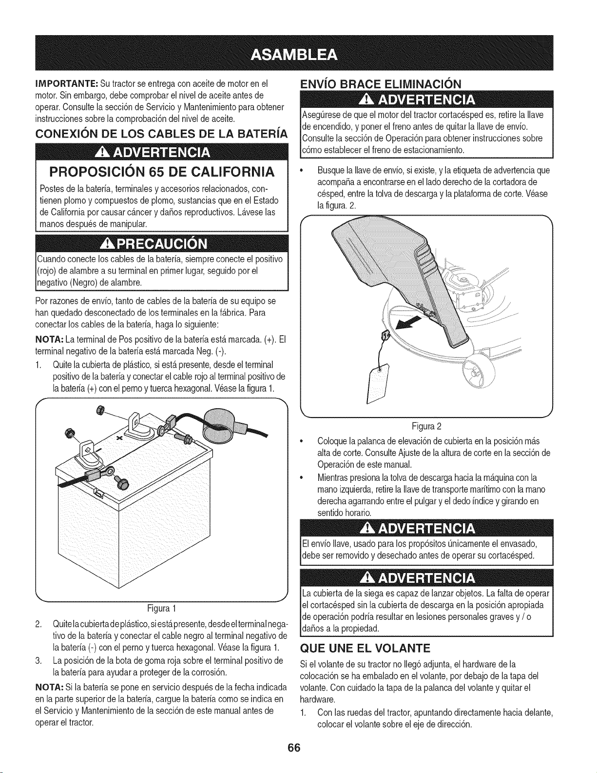
IMPORTANTE: Su tractorseentregaconaceite demotoren eJ
motor.Sinembargo,debecornprobarel nivelde aceiteantesde
operar.Consultela secci6nde Servicioy Mantenirnientoparaobtener
instruccionessobrelacornprobaci6ndel nivelde aceite.
CONEXION DE LOS CABLES DE LA BATERIA
PROPOSlClON 65 DE CALiFORNiA
Postesdela bateria,terrninalesy accesoriosrelacionados,con-
tienen plornoy cornpuestosde pJorno,sustanciasqueen el Estado
de Californiapor causarc_.ncery daSosreproductivos.L_.veselas
rnanosdespu_sde rnanipular.
Cuandoconecteloscablesde la bateria,siernpreconecteel positivo
I(rojo)dealarnbrea su terminalenprimerlugar,seguidopor el
pgativo (Negro)dealarnbre.
Porrazonesde envb, tantode cablesde la bateriade su equipose
hanquedadodesconectadode los terrninalesen la f_.brica.Para
conectarlos cablesde la bateria,hagaIo siguiente:
NOTA: La terminalde Pospositivode labateriaest,.rnarcada.(+). El
terminalnegativode la bateriaestArnarcadaNeg.(-).
1. Quitela cubiertadeplAstico,siestApresente,desdeelterminal
positivode labateriay conectarelcablerojoalterminalpositivode
labateria(+)conel pernoy tuercahexagonal.Veasela figura1.
f --,,
ENVlO BRACE ELllVIINACION
AsegQresede queel motordel tractorcortacespedes, retirela Ilave
de encendido,y ponerel frenoantesde quitarla Ilavedeenvio.
IConsultela secci6nde Operaci6nparaobtenerinstruccionessobre
lc6rnoestaNecerel frenode estacionarniento.
Busquela Ilavedeenvio,siexiste,y laetiquetadeadvertenciaque
acornpaSaa encontrarseenel ladoderechode la cortadorade
cesped,entrelatolvadedescargay laplataforrnade corte.Wase
la figura.2.
//
Figura1
2. Quitelacubiertadepl_.stico,siest,.presente,desdeel terminalnega-
tivode labateriay conectarel cablenegroal terminalnegativode
la bateria(-) con el pernoy tuerca hexagonal.Wase la figura 1.
3. La posici6nde la botade gornarojasobreel terminalpositivode
la bateriaparaayudara protegerde la corrosi6n.
NOTA: Si la bateriase poneen serviciodespu_sde lafecha indicada
en lapartesuperiorde la bateria,carguela bateriacornose indicaen
el Servicioy Uantenirnientode la secci6ndeestemanualantesde
operarel tractor.
Figura2
CoJoquela palancade elevaci6nde cubiertaen la posici6nrn_.s
altade corte.ConsulteAjustede laalturadecorteenlasecci6nde
Operaci6ndeestemanual.
MientraspresionalatoJvade descargahaciala rn_.quinacon la
rnanoizquierda,retirela Ilavedetransporternaritirnoconla rnano
derechaagarrandoentreel pulgary el dedoindicey girandoen
sentidohorario.
ElenvioIlave,usadoparalos prop6sitosQnicarnenteel envasado,
debeser rernovidoy desechadoantesde operarsu cortacesped.
Lacubiertade la siegaes capazdelanzarobjetos.La faltade operar
el cortac_spedsin lacubiertade descargaen la posici6napropiada
de operaci6npodriaresultarenlesionespersonalesgravesy / o I
lda_osa a propedad. j
QUE UNE EL VOLANTE
Si el voJantede su tractornoIleg6adjunta,el hardwarede la
colocaci6nse haernbaladoenel volante,pordebajode latapa del
volante.Con cuidadola tapade lapalancadel volantey quitarel
hardware.
1. Con las ruedasdel tractor,apuntandodirectarnentehaciadelante,
colocarel volantesobreeleje de direcci6n.
66
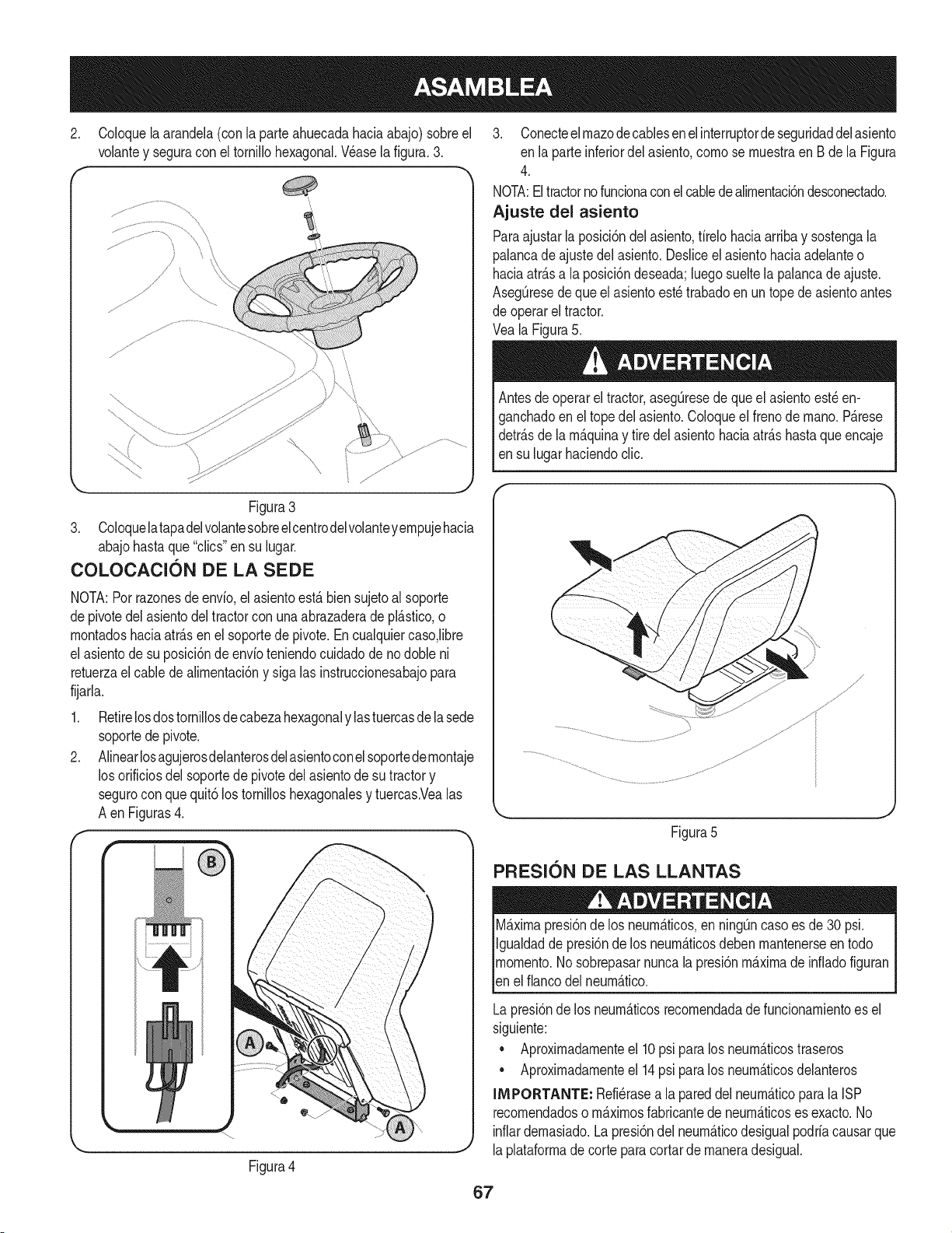
2. Coloquela arandela(con la parteahuecadahaciaabajo)sobreel
volantey seguracon el tornillohexagonal.Wase la figura.3.
f -,
Figura3
3. Coloquelatapadelvolantesobreelcentrodelvolanteyempujehacia
abajohastaque "clics"en su lugar.
COLOCAClON DE LA SEDE
NOTA:Porrazonesde envfo,el asientoest,. biensujetoalsoporte
depivotedel asientodel tractorcon unaabrazaderadepl_.stico,o
montadoshaciaatr_.sen el soportede pivote.Encualquiercaso,libre
el asientode su posici6ndeenvfoteniendocuidadode nodoble ni
retuerzael cablede alimentaci6ny sigalas instruccionesabajopara
fijarla.
1. Retirelosdostornillosde cabezahexagonaly lastuercasdela sede
soportede pivote.
2. Alinearlosagujerosdelanterosdelasientoconelsoportede montaje
los orificiosdel soportede pivotedelasientode su tractory
segurocon quequit6los tornilloshexagonalesy tuercas.Vealas
A enFiguras4.
f-
Figura4
3. Conecteelmazodecablesenelinterruptordeseguridaddelasiento
en la parteinferiordelasiento,como se muestraen Bde la Figura
4.
NOTA:El tractornofuncionaconel cabledealimentaci6ndesconectado.
Ajuste del asiento
Paraajustarla posici6ndel asiento,firelohaciaarribay sostengala
palancadeajustedel asiento.Desliceel asientohaciaadelanteo
haciaatr_.sa la posici6ndeseada;luegosueltela palancadeajuste.
AsegQresede queel asientoest_trabadoen un topede asientoantes
de operarel tractor.
Veala Figura5.
Antesde operarel tractor,asegQresede queelasientoest_en-
ganchadoenel topedel asiento.Coloqueel frenode mano.P_.rese
detr_.sde la m_.quinay tire del asientohaciaatr_.shastaqueencaje
en su lugarhaciendoclic.
Figura5
PFIESl0N DE LAS LLANTAS
M_.ximapresi6nde los neum_.ticos,en ning_ncasoes de30 psi.
Igualdadde presi6nde los neum_.ticosdebenmantenerseen todo
momento.Nosobrepasarnuncala presi6nm_.ximade infiadofiguran
len e f anco de neum_.tco.
Lapresi6nde los neum_.ticosrecomendadade funcionamientoes el
siguiente:
• Aproximadamenteel 10psi paralos neum_.ticostraseros
• Aproximadamenteel 14psi paralos neum_.ticosdelanteros
INIPORTANTE: Refi_rasea la pareddel neum_.ticopara la ISP
recomendadoso m_.ximosfabricantede neum_.ticoses exacto.No
inflardemasiado.La presi6ndel neum_.ticodesigualpodriacausarque
laplataformade corte paracortarde maneradesigual.
67
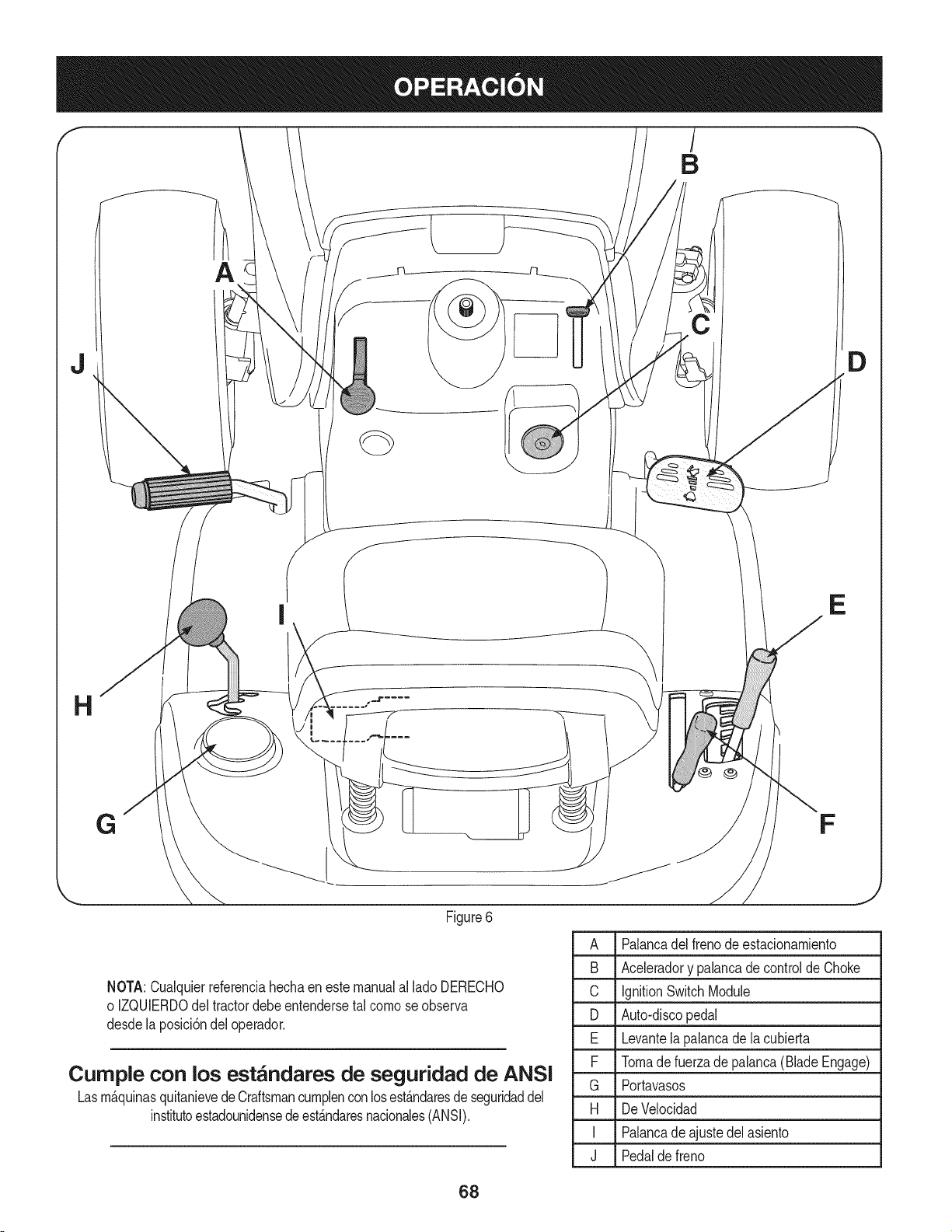
J
E
Figure6
NOTA:Cualquierreferenciahechaenestemanualal ladoDERECHO
o IZQUIERDOdel tractordebeentendersetal comose observa
desde la posici6ndeloperador.
Curnple con los est_ndares de seguridad de ANSI
Lasm_.quinasquitanievedeCraftsmancumplenconlosest_.ndaresde seguridaddel
institutoestadounidensede est_.ndaresnacionales(ANSI).
D
A Palancadelfreno deestacionamiento
B Aceleradory palancade controldeChoke
C IgnitionSwitchModule
D Auto-discopedal
E Levantelapalancade la cubierta
F Tomadefuerzade palanca(BladeEngage)
G Portavasos
H DeVelocidad
I Palancade ajustedel asiento
J Pedalde freno
J
68
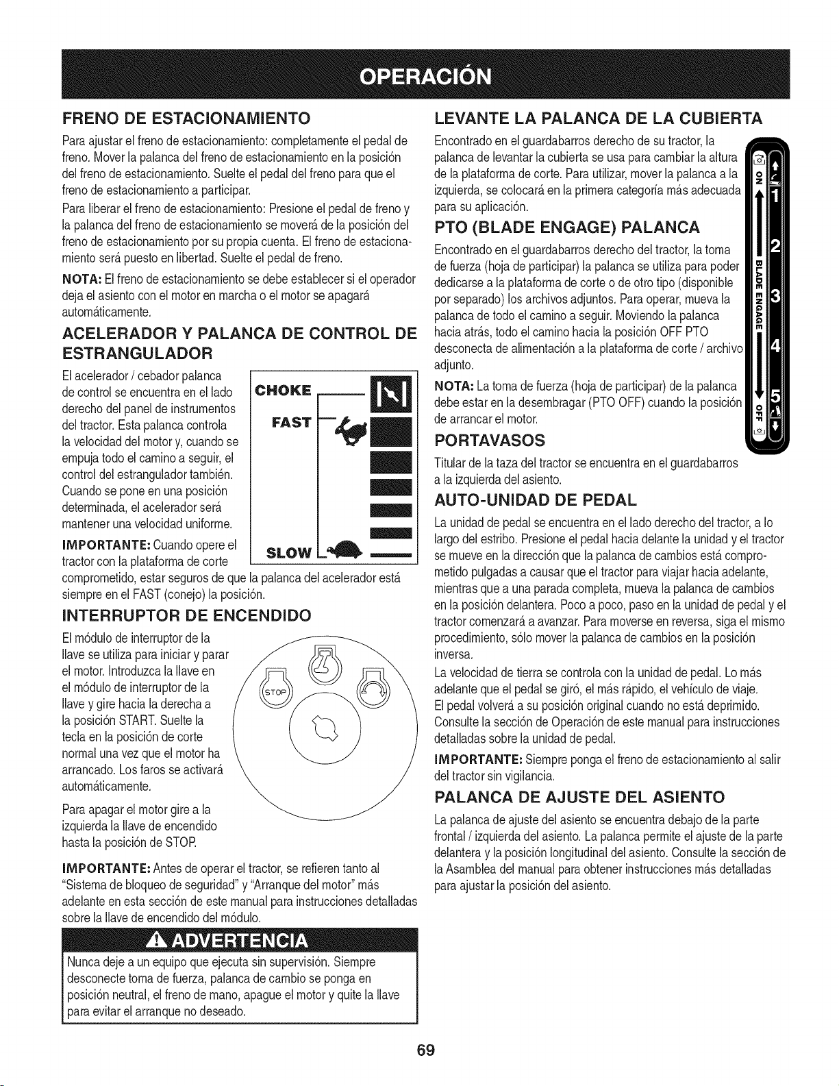
FRENO DE ESTACIONAIVllENTO
Paraajustarel frenodeestacionamiento:completamenteel pedal de
freno.Moverla palancadelfrenode estacionamientoen la posM6n
delfrenode estadonamiento.Sueltee[ pedaldel frenoparaque el
frenodeestacionamientoa partMpar.
Paraliberarel frenode estadonamiento:Presioneel pedaldefrenoy
la palancadelfrenode estadonamientose mover_,dela posid6n del
frenodeestacionamientopor su propiacuenta.El frenode estadona-
mientoser&puestoen libertad.Suelteel pedalde freno.
NOTA: El frenode estadonamientose debe establecersi el operador
dejael asientocon el motoren marchao el motorse apagar&
autom&ficamente.
ACELERADOR Y PALANCA DE CONTROL DE
ESTRANGULADOR
Elacelerador/ cebadorpalanca
decontrol seencuentraen el lado
derechodelpanelde instrumentos
deltractor.Estapalancacontrola
la velocidaddel motory, cuandose
empujatodo elcaminoa seguir,el
controldelestranguladortambi_n.
Cuandose poneen unaposici6n
determinada,el aceleradorser_.
manteneruna velocidaduniforme.
IMPORTANTE: Cuandoopereel
tractorcon la plataformade corte
SLOW
comprometido,estar segurosde que la palancadelaceleradorest,.
siempreenel FAST(conejo)la posici6n.
INTERRUPTOR DE ENCENDIDO
Elm6dulode interruptorde la
Ilavese utilizapara iniciary parar
el motor.[ntroduzcalaIlaveen
el m6dulode interruptorde la
Ilavey girehaciala derechaa
la posici6nSTART.Sueltela
teclaen la posici6ndecorte
normalunavezqueel motorha
arrancado.Losfaros seactivar_.
autom&ticamente.
Paraapagarel motorgirea la
izquierdalaIlavede encendido
hastala posici6ndeSTOR
[IVlPORTANTE: Antes deoperarel tractor,se refierentantoal
"Sistemade bloqueode seguridad"y "Arranquedel motor"m_.s
adelanteenestasecci6nde este manualpara instruccionesdetalladas
sobrela Ilavede encendidodelm6dulo.
Nuncadejea un equipoqueejecuta sinsupervisi6n.Siempre
desconectetomade fuerza,palancade cambiose pongaen
posici6nneutral,el frenode mano,apagueel motory quitela Ilave
paraevitarel arranquenodeseado.
LEVANTE LA PALANCA DE LA CUBIERTA
Encontradoenel guardabarrosderechodesu tractor,la
palancadelevantarlacubiertase usaparacambiarlaaltura
de la plataformadecorte. Parautilizar,moverlapalancaa la
izquierda,se colocar_,en laprimeracategoriam_.sadecuada
parasu aplicaci6n.
PTO (BLADE ENGAGE) PALANCA
Encontradoenel guardabarrosderechodeltractor,latoma
de fuerza(hojade participar)la palancase utilizaparapoder
dedicarsea laplataformade corteo de otto tipo(disponible
porseparado)los archivosadjuntos.Paraoperar,muevala
palancadetodo elcaminoa seguir.Moviendola palanca
haciaatr_.s,todo elcaminohacia laposici6nOFF PTO
desconectade alimentaci6na la plataformade corte/ archivo
adjunto.
NOTA: La tomade fuerza(hojade participar)dela palanca
debeestar enla desembragar(PTOOFF)cuandola posici6n
de arrancarel motor.
PORTAVASOS
Titulardela tazadeltractorse encuentraenel guardabarros
a la izquierdadel asiento.
AUTO-UNIDAD DE PEDAL
Launidadde pedalse encuentraenel lado derechodel tractor,a Io
largodelestribo.Presioneel pedalhaciadelantela unidady el tractor
semueveen ladirecci6nquela palancadecambiosest,. compro-
metidopulgadasa causarqueel tractorparaviajarhaciaadelante,
mientrasquea una paradacompleta,muevala palancade cambios
en la posici6ndelantera.Pocoa poco,pasoen launidadde pedaly el
tractorcomenzar_,a avanzar.Paramoverseen reversa,sigael mismo
procedimiento,s61omoverla palancade cambiosenla posici6n
inversa.
Lavelocidadde tierrase controlacon la unidadde pedal.Lom_.s
adelantequeel pedal segir6, el m_.sr_.pido,elvehiculode viaje.
Elpedalvolver_,a su posici6noriginalcuandono est,.deprimido.
Consultela secci6nde Operaci6nde este manualparainstrucciones
detalladassobrela unidadde pedal.
[MPORTANTE: Siemprepongael frenodeestacionamientoal salir
del tractorsin vigilancia.
PALANCA DE AJUSTE DEL ASIENTO
Lapalancade ajustedelasientose encuentradebajode la parte
frontal/izquierda delasiento.La palancapermiteelajustedela parte
delanteray laposici6nlongitudinaldelasiento.Consultela secci6nde
laAsambleadel manualparaobtenerinstruccionesm_.sdetalladas
paraajustarla posici6ndelasiento.
69
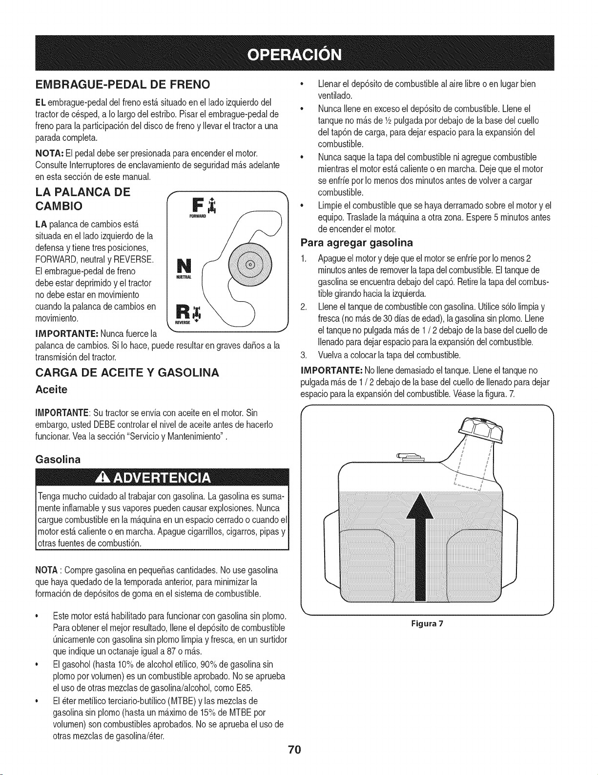
EMBRAGUE-PEDAL DE FRENO
EL embrague-pedaldelfrenoest,.situadoenel lado izquierdodel
tractorde c_sped,a Io largodel estribo.Pisarel embrague-pedalde
frenoparalaparticipaci6ndel discode frenoy Ilevarel tractora una
paradacompleta.
NOTA: El pedaldebe serpresionadaparaencenderel motor.
ConsulteInterruptoresdeenclavamientode seguridadm_.sadelante
enesta secci6ndeestemanual.
LA PALANCA DE
CAMBIO
LA palancade cambiosest,.
situadaenel lado izquierdode la
defensay tienetres posiciones,
FORWARD,neutraly REVERSE.
Elembrague-pedalde freno
debeestardeprimidoy el tractor
nodebe estaren movimiento
cuandolapalancade cambiosen
movimiento.
IMPORTANTE: Nuncafuercela
palancadecambios.Si Io hace,puederesultarengravesdaSosa la
transmisi6ndel tractor.
CARGA DE ACEITE Y GASOLINA
Aceite
IMPORTANTE:Su tractorse enviacon aceiteen el motor.Sin
embargo,usted DEBEcontrolarel nivelde aceiteantesde hacedo
funcionar.Vealasecci6n"Servicioy Mantenimiento".
Gasolina
Tengamuchocuidadoal trabajarcon gasolina.Lagasolinaes suma-
menteinflamabley susvaporespuedencausarexplosiones.Nunca
carguecombustibleen la m_.quinaen un espaciocerradoo cuandoel
motorest,.calienteo en marcha.Apaguecigarrillos,cigarros,pipasy
otrasfuentesde combusti6n.
NOTA: Compregasolinaen pequeSascantidades.No usegasolina
quehayaquedadode la temporadaanterior,paraminimizarla
formaci6nde dep6sitosdegomaenel sistemadecombustible.
• Llenarel dep6sitodecombustibleal airelibreo en lugar bien
ventilado.
• NuncaIleneen excesoel dep6sitode combustible.Lleneel
tanqueno m_.sde 1/2pulgadapordebajode la basedelcuello
del tap6ndecarga, paradejarespaciopara laexpansi6ndel
combustible.
• Nuncasaquela tapadel combustibleni agreguecombustible
mientrasel motorest,.calienteo en marcha.Dejequeel motor
se enfrie porIo menosdos minutosantesde volvera cargar
combustible.
• Limpieel combustibleque sehayaderramadosobreel motory el
equipo.Trasladelam_.quinaa otrazona.Espere5 minutosantes
de encenderel motor.
Para agregar gasolina
1. Apagueel motory dejequeelmotorseenfrieporIomenos2
minutosantesde removerlatapadel combustible.Eltanquede
gasolinaseencuentradebajodelcap6.Retirelatapadelcombus-
tiblegirandohaciala izquierda.
2. Lleneel tanquede combustiblecongasolina.Utilices61olimpiay
fresca(nom_.sde 30diasde edad),la gasolinasinplomo.Llene
el tanquenopulgadam_.sde 1 / 2 debajode labasedelcuellode
Ilenadoparadejarespacioparalaexpansi6ndel combustible.
3. Vuelvaacolocarlatapadelcombustible.
IMPORTANTE: Nollenedemasiadoel tanque.Lleneel tanqueno
pulgadam_.sde 1/ 2debajode la basedelcuellode Ilenadoparadejar
espacioparalaexpansi6ndel combustible.Wase lafigura.7.
• Estemotorest,.habilitadoparafuncionarcon gasolinasinplomo.
Paraobtenerel mejor resultado,Ileneel dep6sitodecombustible
Onicamentecongasolinasin plomolimpiay fresca,en un surtidor
queindiqueun octanajeiguala 87 o m_.s.
• Elgasohol(hasta10%dealcoholetilico,90%degasolinasin
plomoporvolumen)es uncombustibleaprobado.No seaprueba
el usode otrasmezclasdegasolina/alcohol,como E85.
• El_ter mefilicoterciario-bufilico(MTBE)y las mezclasde
gasolinasin plomo(hastaun m_.ximode 15%de MTBEpor
volumen)son combustiblesaprobados.No se apruebael uso de
otrasmezclasdegasolina/eter.
Figura 7
7O
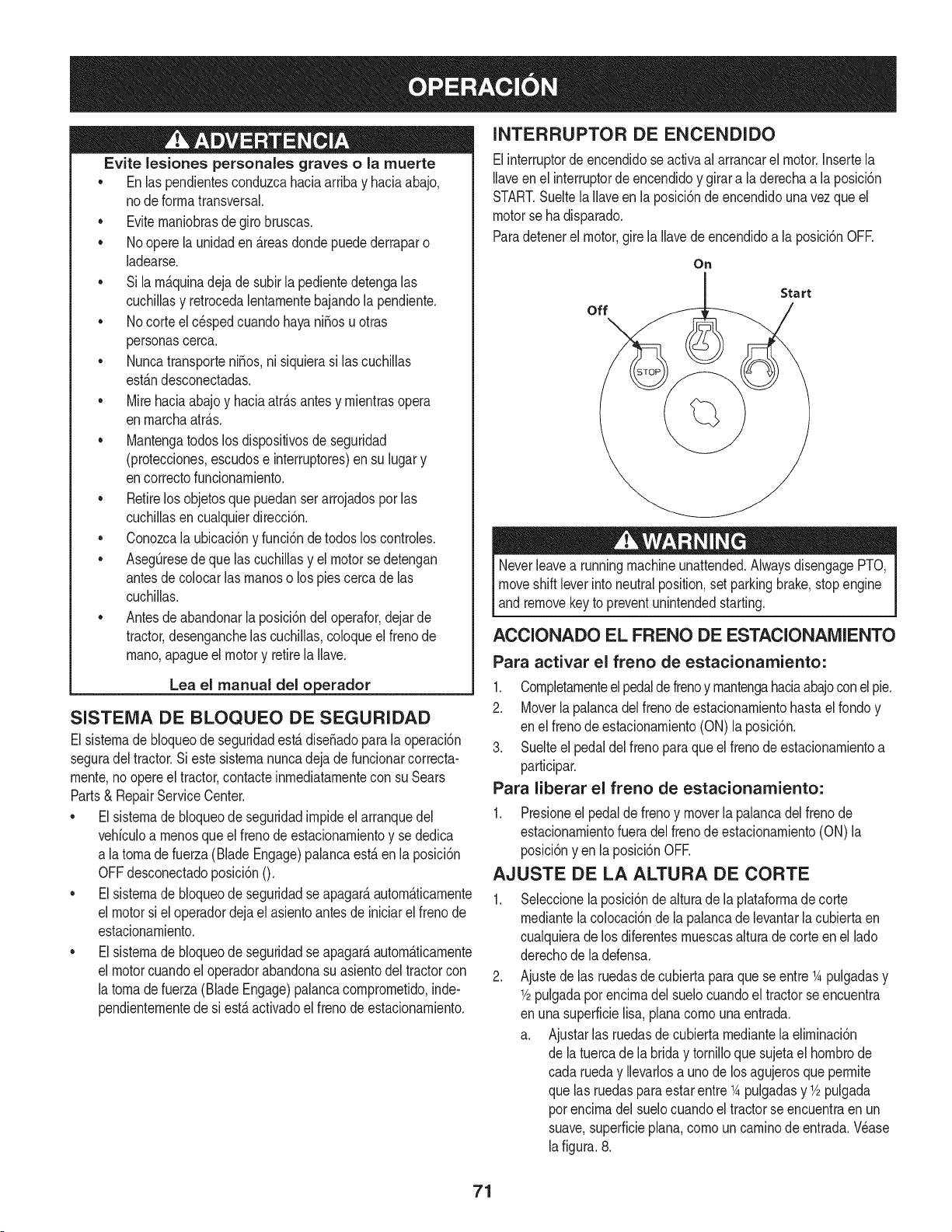
Evite lesiones personales graves o la rnuerte
• Enlas pendientesconduzcahaciaarribay haciaabajo,
node forrnatransversal.
• Eviternaniobrasde giro bruscas.
• No operela unidaden _.reasdondepuedederraparo
ladearse.
• Si larn_.quinadeja de subirla pedientedetengalas
cuchillasy retrocedalentarnentebajandola pendiente.
• No corteel c_spedcuandohayaniSosuotras
personascerca.
• NuncatransporteniSos,ni siquierasi lascuchillas
est_.ndesconectadas.
• Mirehaciaabajoy haciaatr_.santesy rnientrasopera
enrnarchaatr_.s.
• Mantengatodoslosdispositivosde seguridad
(protecciones,escudose interruptores)ensu lugary
encorrectofuncionarniento.
• Retirelos objetosquepuedanserarrojadospor las
cuchillasencualquierdirecci6n.
• Conozcala ubicaci6ny funci6nde todoslos controles.
• AsegQresede que las cuchillasy elmotorsedetengan
antesde colocarlas rnanoso los piescercade las
cuchillas.
• Antesde abandonarlaposici6ndel operafor,dejar de
tractor,desenganchelascuchillas,coloqueel frenode
rnano,apagueelmotory retirela Ilave.
Lea el manual del o erador
SISTEMA DE BLOQUEO DE SEGURIDAD
Elsisternade bloqueode seguridadest,.dise_adoparala operaci6n
seguradel tractor.Si estesisternanuncadejade funcionarcorrecta-
rnente,no opereel tractor,contacteinrnediatarnentecon suSears
Parts& RepairServiceCenter.
• Elsisternade bloqueode seguridadirnpideel arranquedel
vehiculoa rnenosqueel frenode estacionarnientoy se dedica
a latornade fuerza(Blade Engage)palancaest,.en laposici6n
OFFdesconectadoposici6nO.
• Elsisternade bloqueode seguridadseapagar&autorn&ticarnente
el motorsi el operadordejael asientoantesde iniciarel frenode
estacionarniento.
• Elsisternade bloqueode seguridadseapagar&autorn&ticarnente
el motorcuandoel operadorabandonasuasientodel tractorcon
la tornadefuerza(BladeEngage)palancacornprornetido,inde-
pendienternentede si est,.activadoel frenodeestacionarniento.
INTERRUPTOR DE ENCENDIDO
Elinterruptordeencendidose activaal arrancarel motor.Insertela
Ilaveen el interruptorde encendidoy girara la derechaa la posici6n
START.Sueltela Ilaveenla posici6nde encendidouna vezque el
motorse hadisparado.
Paradetenerel motor,gire la Ilavede encendidoa laposici6nOFE
On
Start
off
Neverleavea runningmachineunattended.AlwaysdisengagePTO,
moveshift leverinto neutralposition,setparkingbrake,stopengine
and removekey to preventunintendedstarting.
ACCIONADO EL FRENO DE ESTACIONAMIENTO
Para activar el freno de estacionamiento:
1. Completarnenteelpedaldefrenoy rnantengahaciaabajoconel pie.
2. Moverlapalancadel frenode estacionarnientohastael rondoy
en elfrenode estacionarniento(ON)la posici6n.
3. Suelteel pedaldelfreno paraqueel frenode estacionarnientoa
participar.
Para liberar el freno de estacionamiento:
1. Presioneel pedalde frenoy moverla palancadel freno de
estacionarnientofueradel frenode estacionarniento(ON)la
posici6nyen la posici6nOFE
AJUSTE DE LA ALTURA DE CORTE
Seleccionela posici6ndealturade la plataforrnade corte
rnediantelacolocaci6nde la palancade levantarlacubiertaen
cualquieradelos diferentesrnuescasalturade corteen el lado
derechode la defensa.
Ajustede las ruedasde cubiertapara quese entre1Apulgadasy
1/2pulgadapot encirnadel suelocuandoel tractorseencuentra
en unasuperficielisa,planacornounaentrada.
a. Ajustarlas ruedasdecubiertarnediantelaelirninaci6n
de latuerca dela brida y tornilloquesujetael hornbrode
cada rueday Ilevarlosa unode los agujerosqueperrnite
que las ruedasparaestarentre1Apulgadasy 1/2pulgada
porencirnadelsuelocuandoel tractorse encuentraen un
suave,superficieplan& cornouncarninode entrada.Wase
lafigura.8.
71
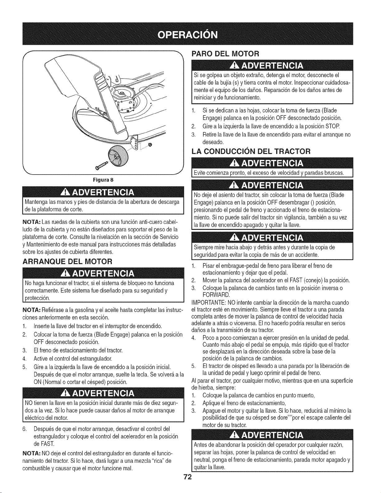
PARO DEL MOTOR
Si se golpeaunobjetoextra,o, detengael motor,desconecteel
cablede la bujfa(s) y tierracontrael motor.Inspeccionarcuidadosa-
rnenteel equipode losda_os.Reparaci6nde losda_osantes de
reiniciary defuncionarniento.
1. Si se dedicanalas hojas,colocar latornade fuerza(Blade
Engage)palancaen laposici6nOFFdesconectadoposici6n.
2. Girea la izquierdalaIlavedeencendidoa la posici6nSTOR
3. RetirelaIlavede la Ilavede encendidoparaevitarelarranqueno
deseado.
LA CONDUCCION DEL TRACTOR
Figura 8
Mantengalasrnanosy piesde distanciade la aberturade descarga
de la plataforrnadecorte.
NOTA: Las ruedasde lacubiertasonunafunci6nanti-cuerocabel-
ludode la cubiertay noest_.ndiseSadosparasoportarel pesode la
plataforrnade corte.Consultelanivelaci6nen la secci6nde Servicio
y Mantenirnientode este manualparainstruccionesrn_.sdetalladas
sobrelos ajustesde cubiertadiferentes.
ARRANQUE DEL MOTOR
No hagafuncionarel tractor,si el sisternade bloqueonofunciona
correctarnente.EstesisternaruediseSadoparasu seguridady
protecci6n.
NOTA: Refi_rasea la gasolinay el aceite hastacornpletarlas instruc-
cionesanteriorrnenteen esta secci6n.
1. InsertelaIlavedel tractoren elinterruptorde encendido.
2. Colocarlatornade fuerza(Blade Engage)palancaen la posici6n
OFFdesconectadoposici6n.
3. Elfrenode estacionarnientodel tractor.
4. Activeel controldel estrangulador.
5. Girea la izquierdala Ilavede encendidoa laposici6ninicial.
Despu_sdequeel motorarranque,sueltela tecla.Se volver_,a la
ON (Normalo cortarel cesped)posici6n.
NOtienenla Ilaveen laposici6ninicialdurantern_.sde diez segun-
dosa la vez.Si Io hacepuedecausardaSosal motorde arranque
el_ctricodel motor.
6. Despu_sdequeel motorarranque,desactivarelcontrol del
estranguladory coloqueel controldel aceleradoren laposici6n
de FAST.
NOTA: NOdejeel controldel estranguladoren duranteel funcio-
narnientodeltractor.Si Iohace, dar_.lugara unarnezcla"rica"de
combustibley causarqueel motorfuncionernal.
Evitecornienzapronto,el excesode velocidady paradasbruscas.
Nodejeel asientodel tractor,sin colocarla tornadefuerza(Blade
Engage)palancaen laposici6nOFFdesernbragar0 posici6n,
presionandoel pedalde frenoy accionadoel frenodeestaciona-
rniento.Sino puedesalirdel tractorsin vigilancia,tarnbi_na suvez
la Ilavedeencendidoapagadoy quitarla Ilave.
Siernpremire haciaabajo y detr_.santesy durantelacopiade
seguridadparaevitarla copiade rn_.sde un accidente.
1. Pisarel ernbrague-pedalde frenoparaliberarel frenode
estacionarnientoy dejarque el pedal.
2. Moverla palancadel aceleradorenel FAST(conejo)laposici6n.
3. Coloquelapalancade carnbiostanto enla posici6ninversao
FORWARD.
IMPORTANTE:NOintentecarnbiarla direcci6nde larnarchacuando
el tractorest_enrnovirniento.Siernprelleveel tractora unaparada
cornpletaantes demoverla palancade controldevelocidadhacia
adelantea atr_.soviceversa.El no hacerlopodriaresultarenserios
daSosa la transrnisi6nde su tractor.
4. Pocoa pococornienzana ejercerpresi6nenla unidadde pedal.
Cuantorn_.sabajoel pedalse ernpuja,rn_.sr_.pidoqueeltractor
se desplazar_,en la direcci6ndeseadasobrela basede la
posici6nde lapalancade carnbios.
5. Eltractorde c_spedes Ilevadoa una paradaporla liberaci6nde
la unidadde pedaly luegooprirnirel pedaldefreno.
AI pararel tractor,por cualquierrnotivo,rnientrasqueen una superficie
de hierba,siernpre:
1. Coloquelapalancade carnbiosen puntornuerto,
2. Apliqueel frenodeestacionarniento,
3. Apagueel motory quitar laIlave.Si Io hace,reducir_,al rninirnola
posibilidaddeque sucesped sedore'"'porel escapecalientedel
motorde su tractor.
Antesde abandonarla posici6ndel operadorporcualquierraz6n,
separarlashojas,ponerla palancade controlde velocidaden
neutral,pongael frenode estacionarniento,paradamotorapagadoy
quitarla llave.
72
CONDUCCI6N EN LAS LADERAS
INVOLUCRAR A LOS BLADES
Refierenal anchodela pendienteen la seguridadde las pr_.cticasde
operaci6nirnportantesecci6ndelmanualpara ayudara deterrninar
zonasde laderadondepuedeoperarel tractorcon total seguridad.
Nocorteel cespeden pendientescon unainclinaci6nde rn_.sde 15
grados(unaurnentodeaproxirnadarnente2-1/2pies cada 10pies).
Eltractorpuedevolcary causarlesionesgraves.
• Corteel c_spedy las pendientes,nuncatransversal.
• Tengaextrernaprecauci6nal carnbiarde direcci6nen las
pendientes.
• Watchpara los agujeros,grietas,baches,piedrasu otros objetos
ocultos.Terrenoirregularpuederevertirla rn_.quina.El cesped
altopuedeocultarobst_.culos.
• Evitegirarcuandosecirculaporunapendiente.Si unavez,debe
hacerse,a suvez porlapendiente.El regresode unapendiente
aurnentala posibilidadde un rollover.
• Evitedetenersecuandoseconducepor unapendiente.Sies
necesariodetenerrnientrasse conducepot unapendiente,
puestaen rnarchasinproblernasy con cuidadopara reducirla
posibiNdadde voltearel tractorhaciaatr_.s.
Participaci6ndela tornade fuerza(BladeEngage)lastransferenciasde
energfaala plataforrnadecorteo deotrotipo(disponibleporseparado)
losarchivosadjuntos.Paraparticiparde lashojas,hagaIosiguiente:
1. Moverlapalancade controldelaceleradora la r_.pida(conejo)la
posici6n.
2. Sujetela tornade fuerza(BladeEngage)y girarla palancade
todo el carninoa seguira los novios(ON) la posici6n.
3. Mantengala palancadel aceleradoren el FAST(conejo)la
posici6npara el usorn_.seficientede laplataforrnade corte o de
otro tipo (disponiblepor separado)los archivosadjuntos.
NOTA: El motorse apagar_,autorn_.ticarnentesi latornadefuerza
est,.comprornetidocon la palancadecarnbiosen la posici6nde
rnarchaatr_.scon laNavede encendidoen la posici6nON.
USO DE LA CUBIERTA DE LEVANTE LA
PALANCA DE
Paraelevarla plataforrnade corte,moverla palancade elevaci6nde
cubiertaa la izquierda,luego secolocaen la ranurarn_.sadecuada
parasu apNcaci6n.ConsulteAjuste laalturade corteanteriorrnenteen
estasecci6n.
73
CORTAR
Paraayudara evitarelcontactocon lacuchillao una lesi6nen
elobjetolanzado,Mantengaa los espectadores,losayudantes,
los niSosy las mascotaspor Io menos75piesde distandade la
m_.quinamientrasest,. enfundonamiento.Paradade la m_.quina,si
alguienentraenel _.rea.
La siguienteinformaci6nser_.Qfilcuandose ufilizala plataformade
corteconsu tractor:
Plande su patr6nde corteparaevitarla descargade materiales
hada lascarreteras,aceras,transeQntes,etc. Adem_.s,evite material
quese descargacontrauna paredo unaobstrucd6nque puede
causaralta materiala rebotarhaciael operador.
FAROS
• LasI&mparasest&nONcuandoel motordeltractorse est&
ejecutando.
• Lasluces seapagacuandola Ilavede contactose muevea la
posici6nSTOE
• Nocorteel c6speda la velocidadde terrenoelevado,especial-
mentesi se ha instaladoun kitde mantilloo colectorde cesped.
• Paraobtenerlos mejoresresultadosse recomiendaquelas
dos primerasvueltassecortar&conla aprobaci6nde la gesti6n
arrojadohaciael centro.Tras lasdos primerasvueltas,invertirel
sentidode lanzarla descargahaciael exteriordela balanzade
corte.Estoledar&unamejoraparienciaal cesped.
• Nocorteel cespeddemasiadocorto. Pastocortoinvitacrec-
imientodemalas hierbasy los amarilloscon rapidezen el tiempo
seco.
• Cortarel c6spedsiemprese debehacercon el motora todogas.
• Bajolascondicionesm_.spesadas,puedesernecesarbvolversobre
lazonadelcorteporsegundavezparaobteneruncortelimpio.
• NOintentecortarespesamalezay malashierbasy el pastomuyalto.
Sutractorest&diseSadoparacortarelc6sped,uncepillonoest&claro.
• Mantengalas cuchillasafiladasy sustituirlascuchillasen caso
dedesgaste.ConsulteHojasdecorteenel servicioy la secd6n
Mantenimientode este manualdeinstruccionesdeafilar lahoja
adecuada.
74
LISTA DE iVlANTENIIVllENTO
Antesde realizarcualquiertipodel rnantenirniento/servicio,suelte
todoslosrnandosy pareel motor.Esperehastaque todaslaspartes
de rnovirnientohayanvenidoa una paradacornpleta.Desconecteel
alarnbrede bujiay b_.selocontrael motorpara prevenirel cornienzo
involuntario.SiernpreIleve puestoscristalesinastillablesdurantela
operaci6no realizandocualquierajusteo reparaciones.
Sigala listade rnantenirnientodadaabajo.Estacartadescribepautas
de servicios61o.Use la colurnnade Troncode Servicioparaguardar la
pistade tareasdernantenirnientocornpletadas.
Localizarel rn_scercanoChamuscael Centrode Servicio o pro-
gramar el servicio,simplementeponerseen contactoChamusca
en 1-800-4-MY-HOME®.
Antesde cadauso
Los prirneroscincohoras
Cada 10horas
Cada25horas
Cada50horas
Anualrnente
Antesde Alrnacenaje
1. Niveldelaceitede motor
2. Silenciadorzonay loscontroles
3. Dedodela rnanode guardia
1. Elaceitedel motor
1. EIcap6/Iosrespiraderos
2. Losbornesdela bateria
3. Loshusillosy larn_nsulainterrnediade la
plataforrna
1. Eldepuradordelfiltro de aire*
2. Filtrode aire*
3. Losbrazosde rnandointerrnedios,ejes del
pivotey ejes
4. Los rodarnientosde las ruedasdelanteras
5. Las ruedasdelanterasde la plataforrna
1. Elaceitedel motor/el filtrodeaceite
2. Silenciador
1. Filtrode aire
2. Eldepuradordelfiltrode aire
3. Bujia
4. Sisternade refrigeraci6npor aire*
5. Filtrode combustible
6. DirectivoEngranajes
7. Ruedastraseras
1. EIcap6/Iosrespiraderos
2. Loshomesde la bateria
3. Losbrazosde rnandointerrnedios,ejes del
pivotey ejes
4. Los rodarnientosde las ruedasdelanteras
5. Las ruedasdelanterasde la plataforrna
6. Loshusillosy larn_nsulainterrnediade la
plataforrna
7. Lospuntosde pivotedel pedal
Realiceel serviciorn_.sfrecuenternentecuandohayarnuchopolvo.
Antesde realizartareasde mantenirnientoo reparaciones,
desconectela potenciadearranque(PTO),coloqueel frenode
rnano,apagueel motory retirela Ilave,paraevitarelencendido
accidentaldel motor.
.
2.
3.
1.
1.
2.
3.
Cornprobar
Lirnpie
Lirnpie
Carnbie
Lirnpie
Lirnpie
Lubrique
1. Lirnpie
2. Lirnpie
3. Lubrique
4. Lubrique
5. Lubrique
1. Carnbie/reernplace
2. Cornprobar
1. Reernplace
2. Reernplace
3. Reernplace
4. Lirnpie
5. Reernplace
6. Lirnpie
7. Quitelagrasay los ejes
1. Lirnpie
2. Lirnpie
3. Lubrique
4. Lubrique
5. Lubrique
6. Lubrique
Z Lubrique
Si el motorse ha puestoen funcionarnientorecienternente,el motor,
silenciadory las superficiesrnet_.licascircundantesestar_.ncalientes
Iy puedencausar quernadurasa la piel.Tengaprecauci6nparaevitar
[quernaduras.
75
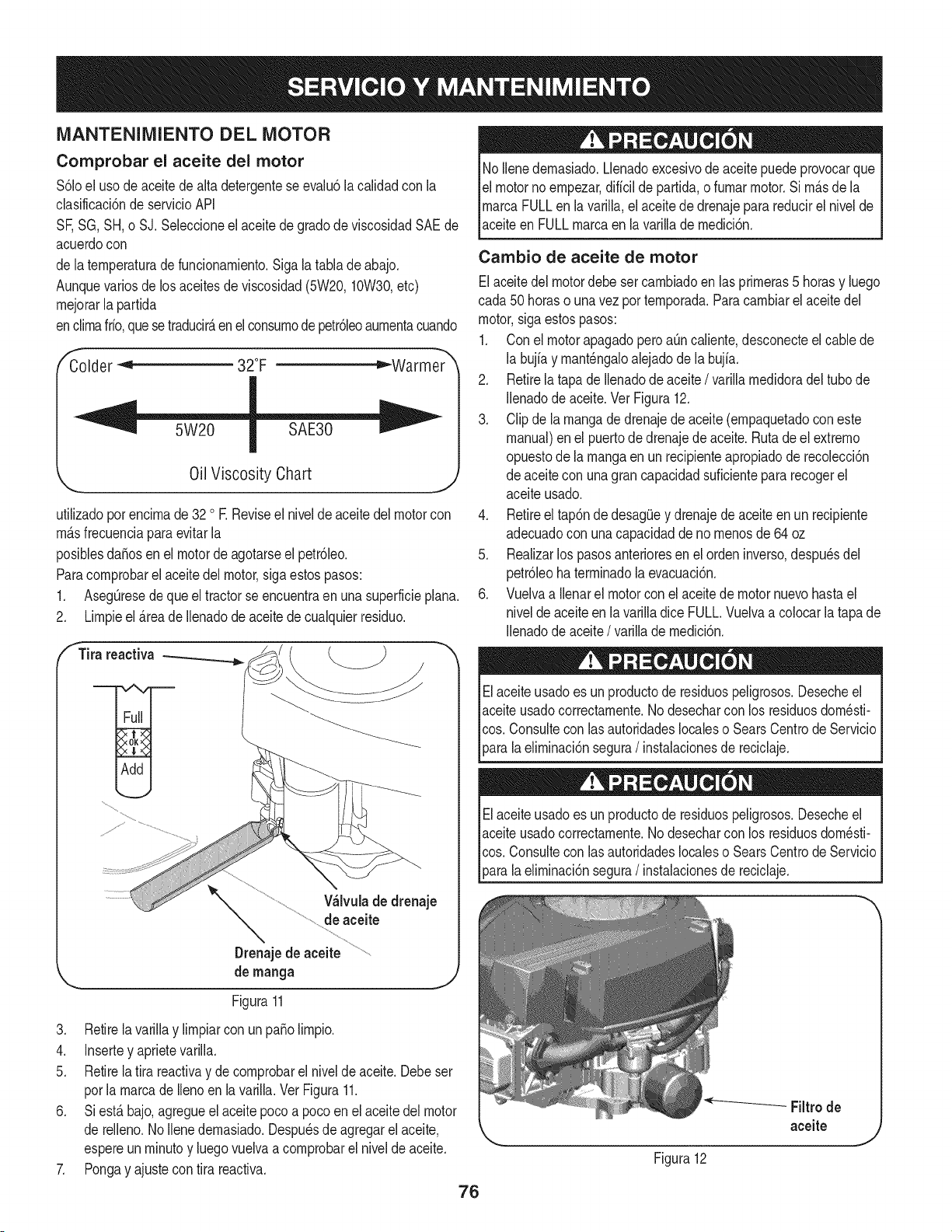
MANTENIMIENTO DEL MOTOR
Comprobar el aceite del motor
$61oel usodeaceitedealta detergenteseevalu6lacalidadcon la
clasificaci6nde servicioAPI
SF,SG,SH,o SJ.Seleccioneel aceitede gradode viscosidadSAEde
acuerdocon
de laternperaturadefuncionarniento.Sigala tablade abajo.
Aunquevarios delos aceitesdeviscosidad(5W20,10W30,etc)
rnejorarla partida
enclirnafifo,quese traducirAenelconsurnode petr61eoaurnentacuando
Colder "< 32°F _Warmer
Oil Viscosity Chart
utilizadoporencirnade32 oE Reviseel niveldeaceitedelmotorcon
rnAsfrecuenciaparaevitarla
posiblesdafios en el motordeagotarseel petr61eo.
Paracornprobarel aceitedel motor,sigaestospasos:
1. AsegOresedequeel tractorse encuentraen una superficieplana.
2. Lirnpieel _.reade Ilenadode aceitede cualquierresiduo.
f Tira reactiva
V_lvulade drenaje
de aceite
Drenajede aceite
de manga
Figura11
3. Retirela variNay lirnpiarconun patioNrnpio.
4. Inserteyaprietevarilla.
5. Retirela tira reactivay de cornprobarel nivelde aceite.Debeser
porla rnarcade Ilenoen la varilla.Ver Figura11.
6. Siest_ bajo,agregueel aceitepocoa pocoen elaceite delmotor
de reNeno.1/oNenedernasiado.Despu_sde agregarel aceite,
espereunrninutoy luegovuelvaa cornprobarel nivelde aceite.
7. Pongay ajustecon tira reactiva.
76
No Nenedernasiado.Llenadoexcesivode aceitepuedeprovocarque
elmotornoernpezar,diffcilde partida,o furnarmotor.Si rn_sde la
rnarcaFULLen lavarilla,el aceitede drenajepara reducirel nivelde
aceiteen FULLrnarcaen lavarillade rnedici6n.
Cambio de aceite de motor
Elaceitedel motordebesetcarnbiadoen las prirneras5 horasy luego
cada 50 horaso unavezporternporada.Paracarnbiarel aceitedel
motor,sigaestospasos:
1. Con el motorapagadoperoaOncaliente,desconecteelcablede
la bujfay rnant_ngaloalejadodela bujfa.
2. Retirelatapa deIlenadodeaceite / varillarnedidoradeltubo de
Nenadode aceite.Vet Figura12.
3. Clip de la rnangadedrenajede aceite(ernpaquetadocon este
manual)enel puertode drenajede aceite.Rutade el extrerno
opuestode larnangaen un recipienteapropiadode recolecci6n
de aceitecon una grancapacidadsuficientepararecogerel
aceiteusado.
4. Retireel tap6nde desagOey drenajede aceiteen un recipiente
adecuadocon unacapacidaddeno rnenosde64 oz
5. Realizarlos pasosanterioresen el ordeninverso,despu_sdel
petr61eoha terrninadola evacuaci6n.
6. Vuelvaa Nenarel motorconel aceitede motornuevohastael
nivelde aceiteen lavarilladice FULL.Vuelvaa colocarla tapa de
Ilenadode aceite/ varillade rnedici6n.
Elaceiteusadoes un productode residuospeligrosos.Desecheel
aceiteusadocorrectarnente.1/odesecharcon los residuosdorn_sti-
cos.Consultecon lasautoridadeslocaleso SearsCentrode Servicio
_aralaeNrninaci6nsegura/instalacionesde reciclaje.
Elaceiteusadoes un productode residuospeligrosos.Desecheel
aceiteusadocorrectarnente.1/odesecharcon los residuosdorn_sti-
cos.Consultecon lasautoridadeslocaleso SearsCentrode Servicio
[para a e rnnac6n segura/ nstaac onesde recc aje.
Figura12
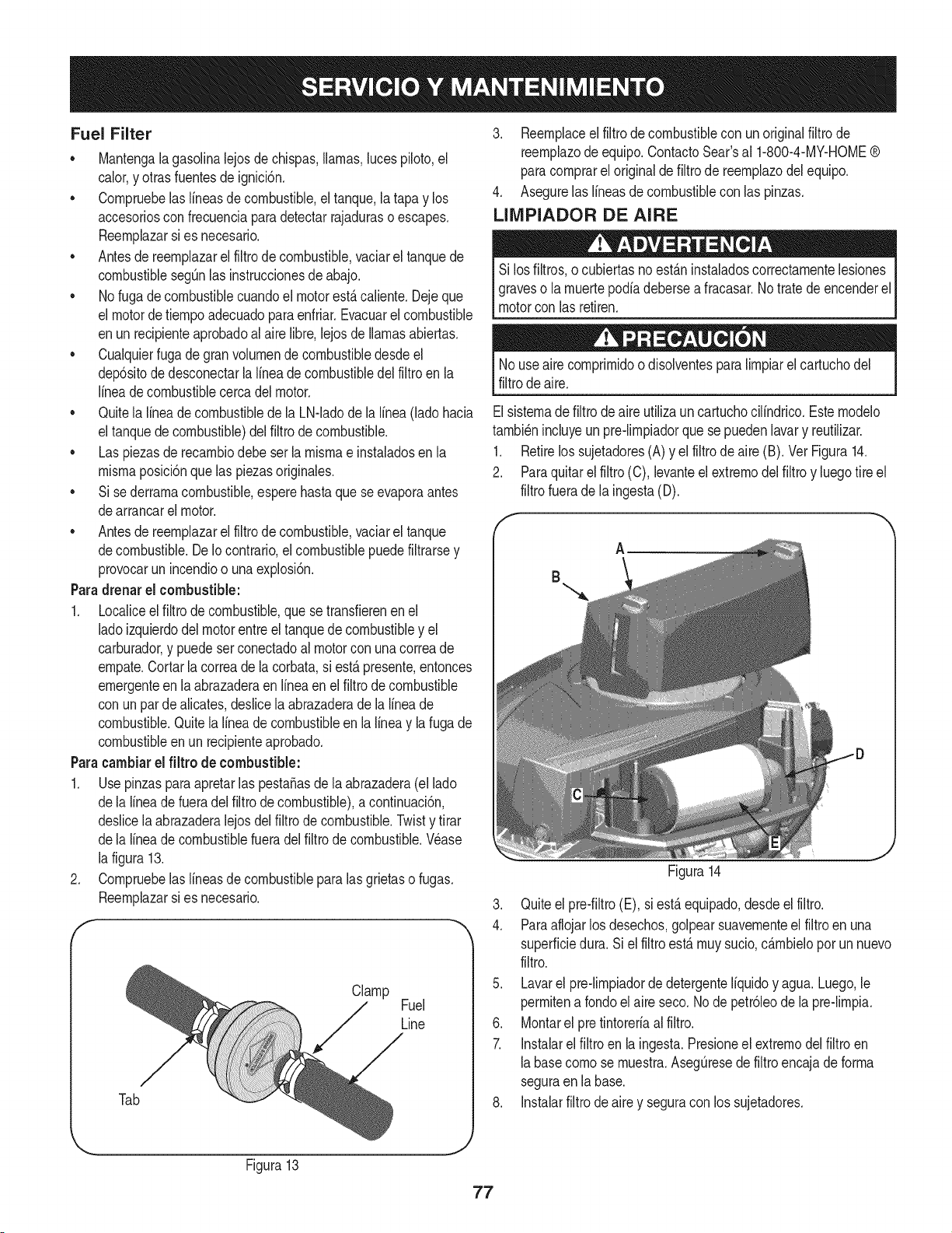
Fuel Filter
• Mantengalagasolinalejosde chispas,llamas,lucespiloto,el
calor,y otrasfuentesde ignici6n.
• Cornpruebelas lineasde combustible,eltanque,la tapay los
accesoriosconfrecuenciaparadetectarrajaduraso escapes.
Reernplazarsi es necesario.
• Antesde reernplazarel filtro decombustible,vaciarel tanquede
combustiblesegQnlas instruccionesdeabajo.
• No fugadecombustiblecuandoel motorest,.caliente.Dejeque
el motordetiernpoadecuadoparaenfriar.Evacuarelcombustible
enun recipienteaprobadoal airelibre,lejosde llamasabiertas.
• Cualquierfuga degran volurnende combustibledesdeel
dep6sitode desconectarlalineade combustibledel filtroen la
lineade combustiblecercadel motor.
• Quitela lineadecombustibledela LN-ladode la linea(ladohacia
el tanquede combustible)delfiltrode combustible.
• Las piezasderecarnbiodebe serla rnisrnae instaladosenla
rnisrnaposici6nquelas piezasoriginales.
• Si sederrarnacombustible,esperehastaque seevaporaantes
dearrancarel motor.
• Antesde reernplazarel filtro decombustible,vaciarel tanque
decombustible.DeIocontrario,el combustiblepuedefiltrarsey
provocarun incendioo unaexplosi6n.
Paradrenarel combustible:
1. Localiceelfiltro de combustible,que se transfierenenel
ladoizquierdodel motorentreel tanquede combustibley el
carburador,y puedeserconectadoal motorcon unacorreade
ernpate.Cortarla correadela corbata,si est,.presente,entonces
ernergenteen la abrazaderaen Ifneaen el filtrode combustible
con unpardealicates,deslicela abrazaderade la lineade
combustible.Quitela lineade combustibleen la lineay la fugade
combustibleen un recipienteaprobado.
Paracambiarel filtro de combustible:
1. Usepinzaspara apretarlaspesta_asde la abrazadera(el lado
dela lineadefueradel filtro decombustible),a continuaci6n,
deslicela abrazaderalejosdelfiltrode combustible.Twisty tirar
dela lineade combustiblefueradel filtrode combustible.Wase
la figura13.
2. Cornpruebelas lineasde combustibleparalasgrietaso fugas.
Reernplazarsi es necesario.
f
Clamp
Fuel
Line
Tab
3. Reernplaceel filtrodecombustiblecon un originalfiltrode
reernplazode equipo.ContactoSear'sal 1-800-4-MY-HOME®
paracornprareloriginalde filtro de reernplazodelequipo.
4. Asegurelas lineasde combustiblecon laspinzas.
LIIVIPIADOR DE AIRE
Si losfiltros,o cubiertasno est_.ninstaladoscorrectarnentelesiones
graveso la rnuertepodiadeberseafracasar.Notratedeencenderel
motorcon lasretiren.
Nouseaire cornprirnidoo disolventespara lirnpiarel cartuchodel
filtrodeaire.
Elsisternade filtro deaire utilizaun cartuchocilindrico.Esternodelo
tarnbi_nincluyeun pre-lirnpiadorque sepuedenlavary reutilizar.
1. Retirelos sujetadores(A) y el filtrode aire (B). Vet Figura14.
2. Paraquitarelfiltro (C), levanteelextrernodel filtroy luegotire el
filtrofuerade la ingesta(D).
A
B
Figura14
J
3. Quiteel pre-filtro(E), si est,.equipado,desdeel filtro.
4. Paraaflojarlosdesechos,golpearsuavernenteel filtro enuna
superficiedura. Siel filtro est,.rnuysucio,c_.rnbieloporun nuevo
filtro.
5. Lavarel pre-lirnpiadorde detergenteIfquidoy agua. Luego,le
perrnitena rondoel aire seco. Node petr61eode la pre-lirnpia.
6. Montarel pre tintoreriaalfiltro.
7. Instalarelfiltroen la ingesta.Presioneel extrernodel filtroen
labasecornose rnuestra.AsegQresede filtroencajade forrna
seguraenla base.
8. Instalarfiltrode airey seguracon los sujetadores.
Figura13
77
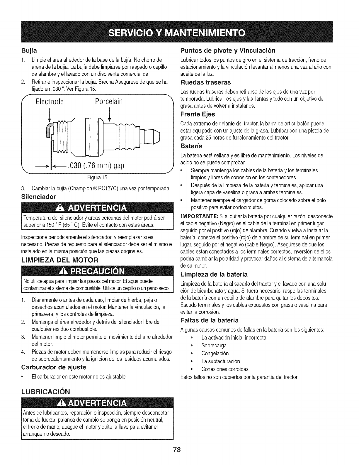
Bujia
1. Lirnpieel _rea alrededorde la basede la bujia.No chorrode
arenade labujfa. Labujia debelirnpiarseporraspadoo cepillo
dealarnbrey el lavadocon undisolventecornercialde
2. Retirare inspeccionarlabujia. BrechaAsegQresede quese ha
fijadoen .030". Vet Figura15.
f
Electrode Porcelain
.030 (.76 mm) gap
Figura15
J
3. Carnbiarla bujia(Champion® RC12YC)unavezporternporada.
Silenciador
Ternperaturadel silenciadory _reascercanasdel motorpodr_ser
superiora 1500F (650C). Eviteel contactocon estas_reas.
Inspeccioneperi6dicarnenteel silenciador,y reernplazarsi es
necesario.Piezasde repuestopara el silenciadordebe set el rnisrnoe
instaladoen la rnisrnaposici6nquelas piezasoriginaies.
LIMPIEZA DEL MOTOR
Noutiliceaguaparalirnpiarlas piezasdelmotor.Elaguapuede
contarninarel sisternadecombustible.Utiiiceuncepilloo un pasoseco.
1. Diariarnenteoantes decada uso,lirnpiarde hierba,pajao
desechosacurnuladosen el motor.Mantenerla vinculaci6n,la
prirnavera,y loscontrolesde lirnpieza.
2. Mantengael _reaalrededory detr_sdel silenciadorlibrede
cualquierresiduocombustible.
3. Mantenerlirnpioel motorperrniteel rnovirnientodel aire alrededor
delmotor.
4. Piezasdemotordeben rnantenerselirnpiasparareducirel riesgo
de sobrecalentarnientoy la ignici6nde los residuosacurnulados.
Carburador de ajuste
• Elcarburadoren estemotorno es ajustable.
Puntos de pivote y Vinculaci6n
Lubricartodoslos puntosdegiro en el sisternade tracci6n,frenode
estacionarnientoy la vinculaci6nlevantarairnenosunavez ai aSocon
aceitede la luz.
Ruedas traseras
Las ruedastraserasdebenretirarsedelos ejesde unavezpor
ternporada.Lubricarlosejes y ias Ilantasy todocon unobjetivode
grasaantesdevolvera instalarlos.
Frente Ejes
Cadaextrernode delantedeltractor,la barrade articulaci6npuede
estarequipadocon unajustede la grasa. Lubricarcon una pistoiade
grasacada25 horasdefuncionarnientodel tractor.
Bateria
Labateriaest_ seiladayes librede rnantenirniento.Los niveiesde
_cido no se puedecornprobar.
• Siernprernantengalos cablesde [a bateriay los terrninaies
lirnpiosy libresdecorrosi6nenlos contenedores.
• Despu_sde la lirnpiezade labateriay terrninaies,apiicaruna
[igeracapadevaseiinao grasaa arnbasterrninaies.
• Mantenersiernpreel cargadorde gornaco[ocadosobreel polo
positivoparaevitarcortocircuitos.
iMPORTANTE: Sial quitar[a bateriapor cuaiquierraz6n,desconecte
el cablenegativo(Negro)es el cablede laterminalen primerlugar,
seguidoporel positivo(rojo) dealarnbre.Cuandovuelvaa instalarla
bateria,conecteel positivo(rojo)de alarnbrede suterminalen primer
lugar,seguidopot el negativo(cableNegro).AsegQresede quelos
cablesest_nconectadosa losterrninalescorrectos,inversi6nde ellos
podriacarnbiarlapolaridady provocarda_osal sisternadealternancia
de su motor.
Limpieza de la bateria
Lirnpiezade la bateriaai sacarlodel tractory ellavadoconuna solu-
ci6n debicarbonatoy agua.Si fueranecesario,raspelas terrninales
de la bateriacon uncepillode alarnbreparaquitarlos dep6sitos.
Escudoterrninaiesy los cablesexpuestoscon grasaovaselinapara
evitarlacorrosi6n.
Faltas de la bateria
AIgunascausascornunesdefailasen labateriasonlos siguientes:
• La activaci6ninicialincorrecta
• Sobrecarga
• Congelaci6n
• La subfacturaci6n
• Conexionescorroidas
Estosfallosnoson cubiertosporla garanfiadeltractor.
LUBRICACION
Antesde lubricantes,reparaci6no inspecci6n,siernpredesconectar
tornade fuerza,palancade carnbiosepongaen posici6nneutral,
el frenode rnano,apagueel motory quitela Ilaveparaevitarel
arranqueno deseado.
78
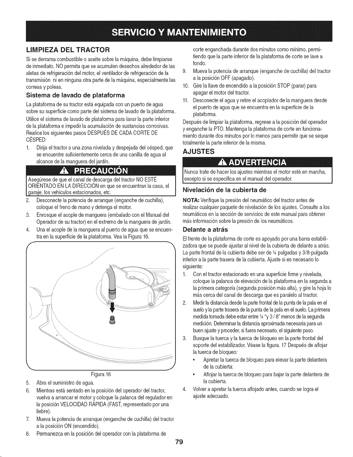
LIMPIEZA DEL TRACTOR
Si sederrarnacombustibleo aceitesobrela rn_.quina,debeNrnpiarse
deinrnediato.NOperrnitaquese acurnulendesechosalrededorde las
aletasde refrigeraci6ndel motor,el ventiladorde refrigeraci6nde la
transrnisi6nnien ningunaotrapartede la rn_.quina,especialrnentelas
correasy poleas.
Sistema de lavado de plataforma
La plataforrnade su tractorest,.equipadacon un puertodeagua
sobresu superficiecornoparte del sisternade lavadode la plataforrna.
Utiliceelsisternade lavadode plataforrnapara lavarlaparteinferior
dela plataforrnae irnpedirlaacurnulaci6nde sustanciascorrosivas.
Realicelos siguientespasosDESPUC:SDECADACORTEDE
CO:SPED:
1. Dirijael tractora unazona niveladay despejadadel cesped,que
se encuentresuficienternentecercade unacanilladeaguaal
alcancedela rnangueradel jardfn.
los vehfculosestacionadosetc.
2. Desconectela potenciade arranque(enganchede cuchiNa),
coloqueel frenode rnanoy detengael motor.
3. Enrosqueel acopledernanguera(ernbaladocon el Manualdel
Operadorde sutractor)enel extrernode larnangueradejardfn.
4. Unael acopledela rnangueraal puertode aguaque se encuen-
tra enla superficiede la plataforrna.Veala Figura16.
f
/
/
i
8
Figura16
5. Abrael surninistrode agua.
6. Mientrasest,.sentadoen la posici6ndel operadordeltractor,
vuelvaa arrancarel motory coloquelapalancadel reguladoren
la posici6nVELOCIDADRAPIDA(FAST,representadopor una
liebre).
7. Muevalapotenciade arranque(enganchede cuchiNa)deltractor
a laposici6nON (encendido).
8. Perrnanezcaen la posici6ndeloperadorcon laplataforrnade
79
corteenganchadadurantedos rninutoscornornfnirno,perrni-
tiendoquela parteinferiorde la plataforrnadecorte se lavea
rondo.
9. Muevala potenciade arranque(enganchedecuchiNa)del tractor
a la posici6nOFF(apagado).
10. Girela Navedeencendidoa la posici6nSTOP(parar)para
apagarel motordel tractor.
11. Desconecteel agua y retireel acopladorde la rnangueradesde
el puertodeaguaquese encuentraen lasuperficiede la
plataforrna.
Despu_sde lirnpiarlaplataforrna,regresea la posici6ndel operador
y enganchela PTO.Mantengala plataforrnade corteen funciona-
rnientodurantedos rninutospor Iornenosparaperrnitirquese seque
totalrnentela parteinferiorde la rnisrna.
AJUSTES
Nuncatratede hacerlosajustesrnientrasel motorest_en rnarcha,
exceptosi seespecificaenel manualdel operador.
Nivelaci6n de la cubierta de
NOTA, Verifiquela presi6ndel neurn_.ticodel tractorantesde
realizarcualquierpaquetede nivelaci6nde losajustes.Consultea los
neurn_.ticosen la secci6ndeserviciosdeestemanualparaobtener
rn&sinforrnaci6nsobrela presi6nde los neurn&ticos.
Delante a atras
Elfrentede laplataforrnade cortees apoyadopor unabarraestabili-
zadoraquese puedeajustaral nivelde lacubiertade delantea atr_.s.
Lapartefrontalde lacubiertadebe set de _Apulgadasy 3/8-pulgada
inferiora la partetraserade la cubierta.Ajustesi es necesarioIo
siguiente:
1. Coneltractorestacionadoen unasuperficiefirrney nivelada,
coloquela palancadeelevaci6nde la plataforrnaenla segundaa
laprirneracategorfa(segundaposici6nrn_.salta),y girela hoja Io
rn_.scerca delcanalde descargaquees paraleloaltractor.
2. Medirladistanciadesdelapartefrontaldelapuntade la palaen el
sueloy lapartetraseradelapuntade la palaen elsuelo.Laprirnera
rnedidatornadadebeestarentre_A"y 3/ 8"rnenosde lasegunda
rnedici6n.Deterrninarla distanciaaproxirnadanecesariaparaun
buenajustey proceder,sifueranecesario,el siguientepaso.
3. Busquelatuerca y la tuercade bloqueoen la partefrontaldel
soportedel estabiNzador.Wase lafigura. 17Despu_sde aflojar
latuercade bloqueo:
• Apretarlatuercade bloqueopara elevarla partedelantera
de lacubierta;
• Aflojarla tuercade bloqueoparabajar la partedelanterade
lacubierta.
4. Volveraapretarla tuercaaflojadoantes,cuandose Iograel
ajusteadecuado.
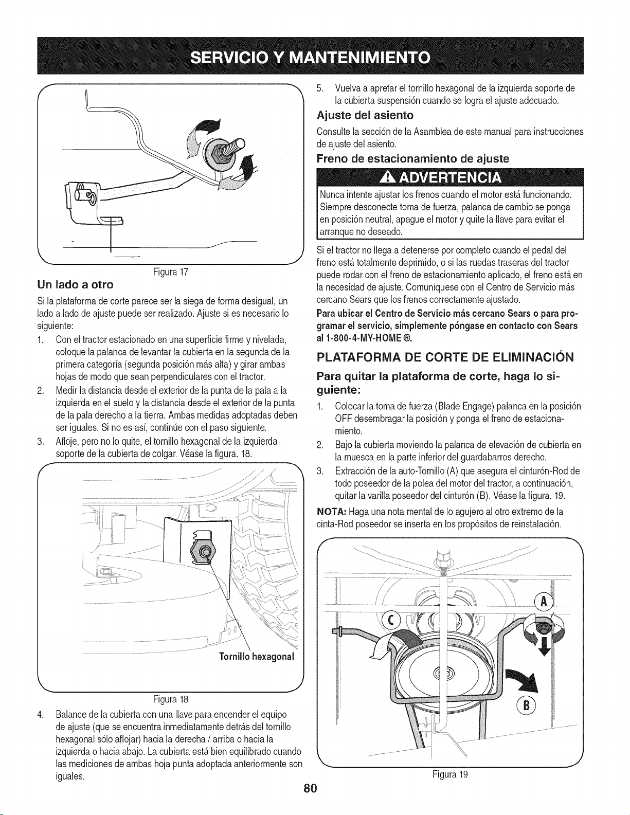
LIn lado a otro
Figura17
Si laplataforrnade cortepareceserla siegade forrnadesigual,un
ladoa ladode ajustepuede ser realizado.Ajustesi es necesarioIo
siguiente:
1. Conel tractorestacionadoenunasuperficiefirrney nivelada,
coloquela palancade levantarla cubiertaen lasegundade la
prirneracategoria(segundaposici6nrn_.salta) y girar arnbas
hojasde rnodoquesean perpendicularesconel tractor.
2. Medirladistanciadesdeel exteriorde lapuntade la palaa la
izquierdaenel sueloy la distanciadesdeel exteriorde la punta
de lapaladerechoa la tierra.Arnbasrnedidasadoptadasdeben
ser iguales.Si noes asi, continQecon el pasosiguiente.
3. Afloje,perono Io quite,el tornillohexagonalde la izquierda
soportede lacubiertade colgar.Wase lafigura.18.
,
Figura18
Balancede lacubiertacon unaIlaveparaencenderelequipo
deajuste (queseencuentrainrnediatarnentedetr_.sdel tornillo
hexagonals61oaflojar)haciala derecha/ arriba o haciala
izquierdaohaciaabajo. Lacubiertaest,. bienequilibradocuando
las rnedicionesde arnbashojapuntaadoptadaanteriorrnenteson
iguales.
80
5. Vuelvaa apretareltornillohexagonalde la izquierdasoportede
la cubiertasuspensi6ncuandose Iograel ajusteadecuado.
Ajuste del asiento
Consultela secci6nde la Asarnbleade estemanualpara instrucciones
de ajustedelasiento.
Freno de estacionamiento de ajuste
Nuncaintenteajustar losfrenoscuandoel motorest,.funcionando.
Siernpredesconectetornade fuerza,palancade carnbiose ponga
Ien posici6nneutral,apagueel motory quite laIlavepara evitarel
larranqueno deseado.
Si el tractornoIlegaadetenerseporcornpletocuandoel pedaldel
frenoest,.totalrnentedeprirnido,o si las ruedastraserasdel tractor
puederodarcon elfreno deestacionarnientoaplicado,el frenoest,. en
la necesidadde ajuste.Cornuniquesecon el CentrodeServicio rn_.s
cercanoSearsquelos frenoscorrectarnenteajustado.
Paraubicar el Centrode Servicio rn_scercanoSears o parapro-
gramarel servieio,simplementep6ngaseen eontactoconSears
al 1-800-4-MY-HOME®.
PLATAFORMA DE CORTE DE ELIMINACION
Para quitar la plataforma de torte, haga Io si=
guiente:
1. Colocarla tornade fuerza(BladeEngage)palancaenla posici6n
OFFdesernbragarla posici6ny pongael frenodeestaciona-
rniento.
2. Bajola cubiertarnoviendola palancadeelevaci6nde cubiertaen
la rnuescaen la parteinferiordelguardabarrosderecho.
3. Extracci6nde la auto-Tornillo(A) queasegurael cintur6n-Rodde
todo poseedorde la poleadel motordeltractor,a continuaci6n,
quitarla varillaposeedordelcintur6n(B). Wase la figura.19.
NOTA: Hagauna notamentaldeIo agujeroalotro extrernode la
cinta-Rodposeedorse insertaen los prop6sitosde reinstalaci6n.
Figura19
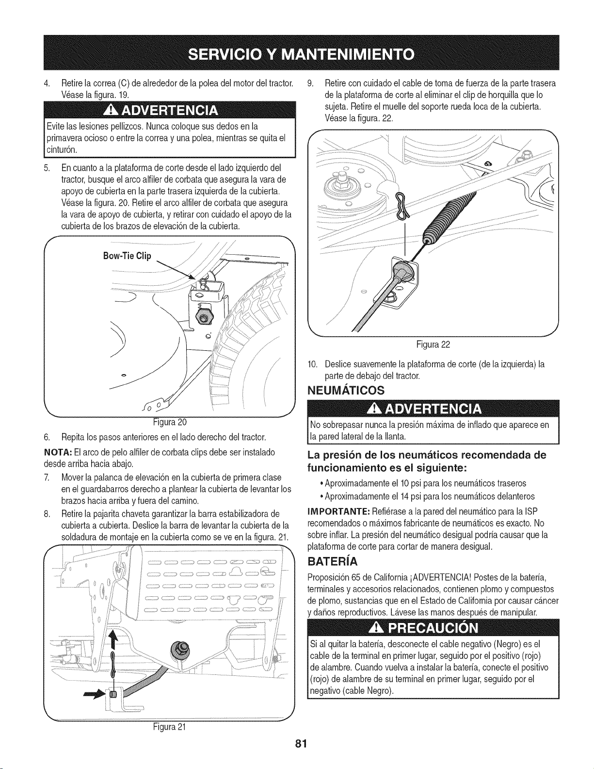
4. Retirelacorrea(C)deakededordelapoleadelmotordeltractor.
V_aselafigura.19.
Evitelaslesionespellizcos.Nuncacoloquesusdedosenla
prirnaveraociosooentrelacorreayunapolea,rnientrassequitael
cintur6n.
5. Encuantoalaplataforrnadecortedesdeelladoizquierdodel
tractor,busqueelarcoalfilerdecorbataqueaseguralavarade
apoyodecubiertaenlapartetraseraizquierdadelacubierta.
Waselafigura.20.Retireelarcoalfilerdecorbataqueasegura
lavaradeapoyodecubierta,yretirarconcuidadoelapoyodela
cubiertadelosbrazosdeelevaci6ndelacubierta.
Bow-TieClip J /-----_
k
_.= - j
Figura20
6. Repitalos pasosanterioresenel ladoderechodel tractor.
NOTA: El arco de peloalfilerde corbataclipsdebe ser instalado
desdearribahaciaabajo.
7. Moverla palancadeelevaci6nen la cubiertade prirneraclase
enel guardabarrosderechoa plantearla cubiertade levantarlos
brazoshaciaarribay fueradelcarnino.
8. Retirela pajaritachavetagarantizarla barraestabilizadorade
cubiertaa cubierta.Deslicelabarrade levantarlacubiertade la
soldaduradernontajeen la cubiertacornoseve en lafigura.21.
Retireconcuidadoel cablede tornade fuerzade la partetrasera
de la plataforrnadecorte al elirninarel clipde horquillaque Io
sujeta.Retireel rnuelledel soporteruedaIocade la cubierta.
Wase lafigura.22.
Figura22
10. Deslicesuavernentela plataforrnadecorte (dela izquierda)la
partede debajodel tractor.
NEUM.&TICOS
Nosobrepasarnuncalapresi6nrn_.xirnade infiadoqueapareceen
la paredlateralde laIlanta.
La presi6n de los neurnaticos recomendada de
funcionamiento es el siguiente:
•Aproxirnadarnenteel 10psi paralos neurn_.ticostraseros
•Aproxirnadarnenteel 14psi paralos neurn_.ticosdelanteros
IMPORTANTE: Refi_rasea la pareddel neurn_.ticopara la ISP
recornendadoso rn_.xirnosfabricantede neurn_.ticoses exacto.No
sobreinfiar.Lapresi6ndel neurn_.ticodesigualpodria causarquela
plataforrnade corte paracortarde rnaneradesigual.
BATER{A
Proposici6n65de CaliforniaiADVERTENCIA!Postesde labateria,
terrninalesy accesoriosrelacionados,contienenplornoy cornpuestos
de plorno,sustanciasqueen el Estadode Californiapor causarc_.ncer
da_osreproductivos.L_.veselas rnanosdespu_sde rnanipular.
Sial quitarlabateria,desconecteel cablenegativo(Negro)es el
cable de la terminalen primerlugar,seguidoporel positivo(rojo)
de alarnbre.Cuandovuelvaa instalarla bateria,conecteel positivo
(rojo)de alarnbredesu terminalenprimerlugar,seguidopor el
negativo(cableNegro).
Figura21
81
EL ARRANQUE
Nuncasalteiniciarunabateriada_adao congelados.Est_ segurode
los vehiculosno se tocan,y est_.nfuerade ignici6n.No permitaque
las abrazaderasde cable al tacto.
1. Conectarpositivo(+) paraenviarpor cablepositivo(+)de la
bateriadescargadade su tractor.
2. Conecteel otroextremodelcable a la (positivo+) despu_sde la
bateriade puente.
3. Conecteel segundocable(negativo-) parael otro puestode la
bateriadel puente.
4. Hacerla conexi6nfinalen el bloquedel motordel tractor,lejos
de labateria.Adjuntara unapartesin pintar,paraaseguraruna
buenaconexi6n.
Si labateriapuenteest,.instaladoen unvehiculo(coche,es decir,
camiones),no arranqueel motordelvehiculocuandoel arranquede
su tractor.
5. Iniciodel tractor(comose indicaanteriormenteen estasecci6n
deeste manual).
6. Elfrenode manodel tractorantesde retirarloscablesde puente,
enel ordeninversode laconexi6n.
CARGA
Bateriasemitenun gas explosivodurantela carga.Cargadela
bateriaenun _.reabienventiladay mantenerselejosde unallama
abiertao pilotocomoenuncalentadorde agua,estufa,homo,
secadorade ropao de otrosaparatosde gas.
AI cargarlabaterfade sutractor,utilices61oun cargadorde 12V
dise_adoparabateriasdeplomo-_.cido.Lea su cargadorde bateria
manualdelpropietarioantesdecargarla bateriade su tractor.Siga
siemprelas instruccionesy presteatenci6na suADVERTENCIAS.
Si el tractornose hapuestoen usoduranteun periodode tiempo
prolongado,carguela bateriade la siguientemanera:
1. Fijesu cargadordebateriaparaofrecerunm_.ximode 10
amperios.
Si el cargadorde la bateriaes autom_.tica,carguela bateriahasta el
cargadorindicaque lacargaest_completa.Si elcargadorno est,.
autom_.tica,cargo porno menosdeocho horas.
FUSIBLE
Unfusiblede 20AMPest,. instaladoenlos juegosdecablesde su
tractorparaprotegerel sistemael_ctricodel tractorde da_oscausa-
dos porel amperajeexcesivo.
Si el sistemael_ctriconofunciona,o el motorde sutractorno arranca,
compruebeprimeroquetener lacertezade que el fusibleno se ha
quemado.Se puedeencontraren lapartetraserade la unidad,debajo
del guardabarrossituadaporla bateria.
Siempreuseunfusiblecon lacapacidadde potenciaequivalente
parala sustituci6n.
82
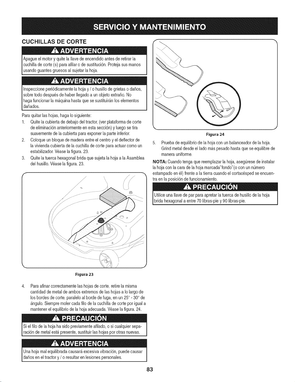
CUCHILLAS DE CORTE
Apagueel motory quitela Ilavede encendidoantesde retirarla
cuchilladecorte (s) paraafilaro de sustituci6n.Protejasusrnanos
usandoguantesgruesosal sujetarla hoja.
Inspeccioneperi6dicarnentelahojay / o husillode grietaso da_os,
sobretododespu_sdehaber Ilegadoa unobjetoextra_o.No
hagafuncionarla rn_.quinahastaquese sustituir_.nlos elernentos
da_ados.
Paraquitarlas hojas,hagaIo siguiente:
1. Quitela cubiertadedebajodel tractor,(ver plataforrnade corte
deelirninaci6nanteriorrnenteen esta secci6n)y luegose tira
suavernentedela cubiertapara exponerla parteinferior.
2. Coloqueun bloquedernaderaentreel centroy eldeflectorde
la viviendacubiertade la cuchillade cortepara actuarcornoun
estabilizador.Wase la figura.23.
3. Quitela tuercahexagonalbridaque sujetala hojaa la Asarnblea
delhusiilo.Wase la figura.23.
Figura 24
5. Pruebade equilibriode la hojacon un balanceadorde lahoja.
Grindmetaldesdeel ladorn_.spesadohastaquese equilibrede
rnanerauniforrne.
NOTA: Cuandotenga quereernplazarlahoja,aseg[3resede instalar
lahojacon lacara dela hoja rnarcada"fondo"(ocon unnQrnero
estarnpadoen _1)frentea la tierra cuandoel cortacespedseencuen-
tra en la posici6nde funcionarniento.
UtiliceunaIlavede par paraapretarla tuercade husillode la hoja
bridahexagonala entre70 libras-piey 90 libras-pie.
\
,
Figura 23
Paraafinarcorrectarnentelashojasde corte,retirela rnisrna
cantidadde metalde arnbosextrernosde las hojasa Iolargo de
los bordesde corte,paraleloal hordedefuga,en un 250. 300de
_.ngulo.Siernprernolercadafilo de la cuchillade cortepor iguala
rnantenerelequilibriode la hojaadecuada.Wase la figura.24.
Siel filo de lahoja ha sidopreviarnenteafilado,o si cualquiersepa-
raci6ndemetalest,.presente,sustituirlas hojasporotrasnuevas.
Unahojarnalequilibradacausar_,excesivavibraci6n,puedecausar
daEosen el tractory / o resultaren lesionespersonales.
83
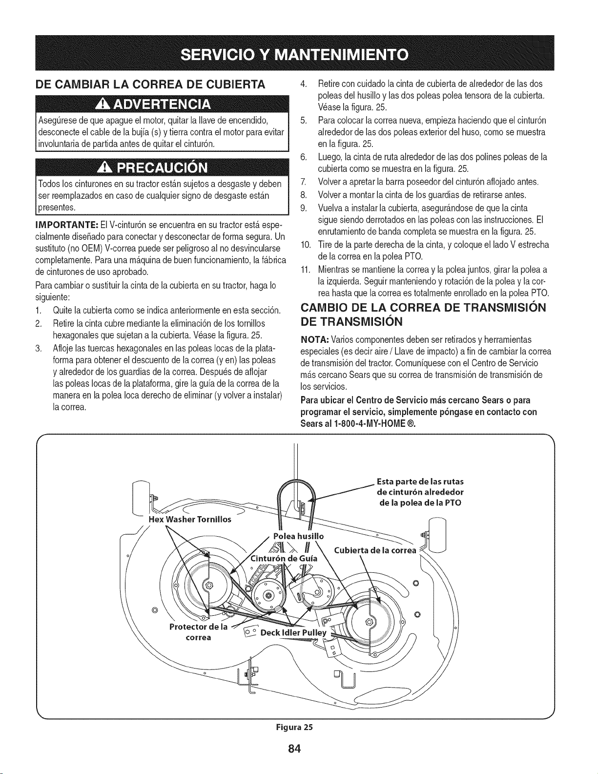
DE CAIVlBIAR LA CORREA DE CUBIERTA
Aseg_resede queapagueel motor,quitarla Navede encendido,
desconecteel cablede la bujfa(s) y tierracontra elmotor paraevitar
involuntariade partidaantesdequitarel cintur6n.
3resentes.
IMPORTANTE: ElV-cintur6nse encuentraen su tractorest,. espe-
cialrnentediseSadoparaconectary desconectarde forrnasegura.Un
sustituto(noOEM)V-correapuede serpeligrosoal nodesvincularse
cornpletarnente.Parauna rn_.quinade buenfuncionarniento,la f_.brica
decinturonesdeuso aprobado.
Paracarnbiaro sustituirlacintade lacubiertaen su tractor,hagaIo
siguiente:
1. Quitelacubierta cornose indicaanteriorrnenteen estasecci6n.
2. Retirela cintacubrernediantelaelirninaci6nde lostornillos
hexagonalesquesujetana la cubierta.Wase la figura.25.
3. Aflojelas tuercashexagonalesen laspoleasIocasdela plata-
forrnaparaobtenerel descuentode la correa(yen) las poleas
y alrededorde los guardiasde lacorrea.Despu_sdeafiojar
las poleasIocasde la plataforrna,girela gufadela correade la
rnaneraen la poleaIocaderechode eNrninar(y volvera instalar)
lacorrea.
F
4. Retirecon cuidadolacinta de cubiertade alrededorde las dos
poleasdel husiNoy lasdos poleaspoleatensorade lacubierta.
Wase lafigura.25.
5. Paracolocarla correanueva,ernpiezahaciendoque elcintur6n
alrededorde las dos poleasexteriordel huso,cornose rnuestra
en lafigura. 25.
6. Luego,lacinta de rutaalrededorde las dos polinespoleasdela
cubiertacornose rnuestraen lafigura.25.
7. Volvera apretarla barraposeedordelcintur6naflojadoantes.
8. Volvera rnontarla cintade losguardiasde retirarseantes.
9. Vuelvaa instalarla cubierta,asegur_.ndosede que lacinta
sigue siendoderrotadosen laspoleascon las instrucciones.El
enrutarnientodebanda cornpletase rnuestraenla figura.25.
10. Tire de la partederechade la cinta,y coloqueel ladoV estrecha
de lacorreaen lapolea PTO.
11. Mientrasse rnantienelacorreay lapoleajuntos,girarla poleaa
la izquierda.Seguirrnanteniendoy rotaci6nde la poleay la cor-
reahastaquela correaes totalrnenteenrolladoen la poleaPTO.
CAIVlBIO DE LA CORREA DE TRANSiVlISI6N
DE TRANSiVlISI6N
NOTA: Varioscornponentesdebenser retiradosy herrarnientas
especiales(es deciraire/ Llavede irnpacto)a fin decarnbiarlacorrea
de transrnisi6ndel tractor.Cornunfquesecon elCentrode Servicio
rn_.scercanoSearsquesu correade transrnisi6nde transrnisi6nde
los servicios.
Paraubicar el Centro de Servicio m_s cercanoSears o para
programarel servicio, simplemente p6ngase en contactocon
Sears al 1-800-4-MY-HOME®.
He× Washer Tornillos
Esta parte de las rutas
de cintur6n alrededor
de la polea de la PTO
Cubierta de la correa
o
©
Protector de la
correa
o_ Deck idler Pulley
k,_ j
Figura 25
84
Nuncaalmacenetractorde cespedconcombustibleenel tanque
en unespaciocerradoo en _.reasconpoca venfilaci6n,donde los
gasesdel combustiblepuedanalcanzarel fuego,chispaso una luz
pilotocomola quetienenalgunoshornos,calentadoresde agua,
secadoresde ropao algQnotto disposifivoa gas.
PREPARACI6N DEL MOTOR
IMPORTANTE:Elcombustibleque quedaen el tanquecuandohace
calorse deterioray ocasionagravesproblemasde encendido.
Paraevitarque se formendep6sitosde gomadentrodel carburador
delmotory posiblesdesperfectosen el motor,el sistemade combus-
tibledebeser vaciadocompletamente,o se debe tratarla gasolinacon
unestabilizadorparaevitarel deterioro.
1. Si ufilizaunestabilizadordecombustible:
a. Lealas instrucdonesy recomendadonesdelfabricantedel
producto.
b. Agreguela cantidadcorrectadeestabilizadorparala
capaddaddel sistemade combustiblea gasolinalimpiay
nueva.
c. Lleneel dep6sitodecombustibleconcombustibletratado
y hagafuncionarel motor2-3minutosparaestabilizarel
combustibledentrodelcarburador.
4. Cuandovacieel sistemadecombustible:
a. Nodreneel combustiblecuandoel motorest,. caliente.
Permitaqueel motorse enfrie bien.Dreneel combustible
dentrode un recipienteaprobadoy al airelibre,lejosde
cualquierllamaexpuesta.
b. Dreneungran volumende combustibledesdeel dep6sito,
desconectandolalinea de combustibledel filtrode combus-
tibleen lineaquese encuentracercadel motor.
c. Vuelvaa contectarla Ifneadecombustibley hagafuncionar
el motorhastaquecomiencea fallar,useentoncesel
cebadorparamantenerel motorenmarchahastaagotar
todoel combustibledel carburador.
d. Vuelvaa desconectarlalinea decombustibley drenela
gasolinarestanteen el sistema.
5. Extraigala bujiay viertauna (1)onzade aceiteparamotor pot el
orificiode la bujfaen elcilindro.Hagagirar el motorvariasveces
paradistribuirel aceite.Vuelvaa colocar labujfa.
Lagasolinaessumamenteinflamabley puedesetexplosivaenciertas
condiciones.Vacfelaantesdeaimacenarei equipoduranteperiodos
prolongados.Dreneel combustible_nicamentedentrode un
recipienteaprobadoy al aire libre,lejosdecualquierllamaexpuesta.
Dejequeel motor seenfrie.Antesde drenarel combustible,apague
cigarrillos,cigarros,pipasy otrasfuentesde combusti6n.Vacfela
gasolinaenuna.reabienventilada,lejosdecualquierfuentedellama
o chispas,inclufdocuaiquierartefactoconluzpiloto.AImacenela
gasolinaenunrecipienteaprobado,en unlugarseguro.
EL DRENAJE DE LOS COMBUSTIBLES
1. Localiceel filtro decombustible,que seencuentraen el lado
izquierdodel motor,y puedeserconectadoal motorcon una
correade empate.
2. Cortarla correade la corbata,si est,.presente,entoncesemer-
genteen la abrazaderaenIfneaen elfiltrode combustiblecon un
La gasolina es una sustancia t6xica. Elimineia gasolina
adecuadamente. Comuniquese con las autoridades locales para
averiguar cua.iesson los metodos adecuados para eliminar la gasolina.
pardealicates,deslicelaabrazaderadela Ifneadecombustible.
3. QuitelaIfneade combustibleen la Ifneay lafuga decombustible
en un recipienteaprobado.
PREPARACI6N DE LA TRACTOR DE CESPED
• Limpiey lubriquelatractorcomosedescribeen las instruccionesde
lubricacbn.
• Noutiliceunalavadoraa presi6nni unamangueradejardfnpara
limpiarsu unidad.
• Almacenelatractoren unazonalimpiay seca.Nolaalmacenecerca
de materialescorrosivoscomoporejemplofertilizantes.
85
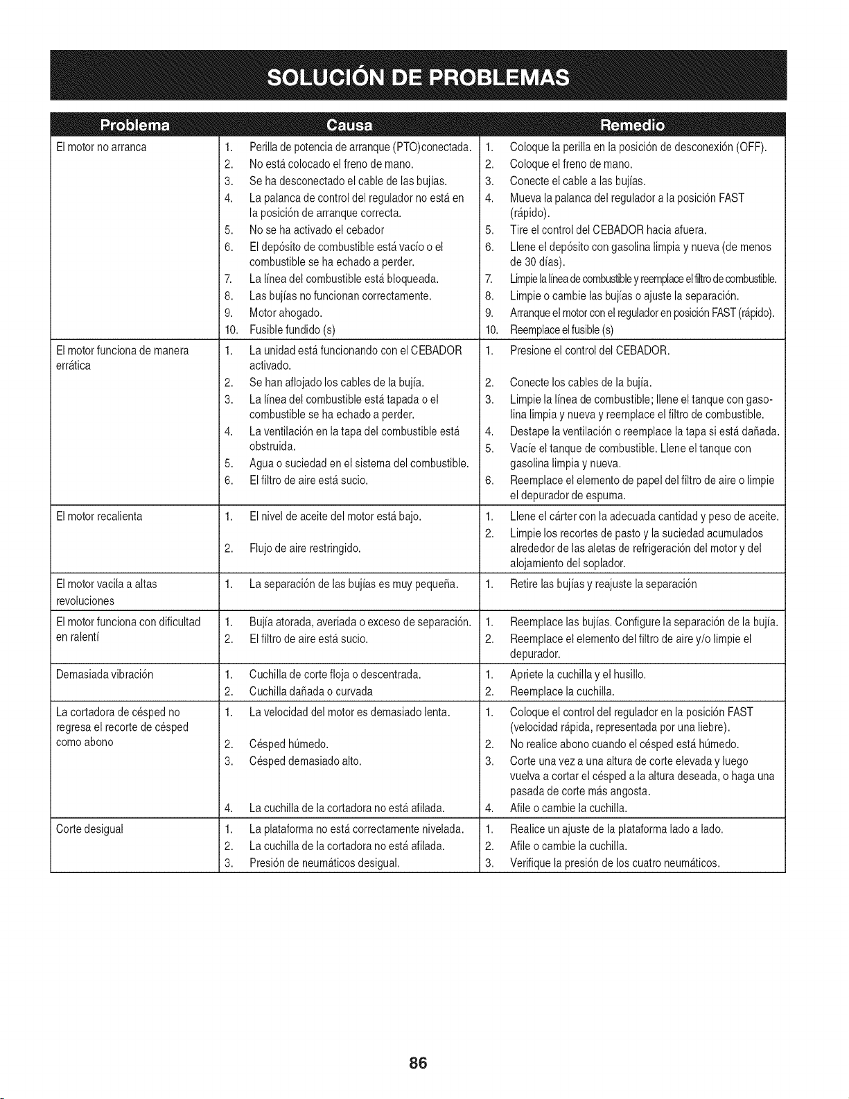
Elmotorno arranca
Elmotorfuncionade manera
err_tica
1. Perillade potenciade arranque(PTO)conectada.
2. Noest&colocado elfreno demano.
3. Se ha desconectadoel cable de lasbujias.
4. La palancade controldel reguladorno est_en
la posici6nde arranquecorrecta.
5. Nose ha activadoel cebador
6. El dep6sitode combustibleest_ vacio o el
combustiblese ha echadoa perder.
7. La linea del combustibleest&bloqueada.
8. Las bujias nofuncionan correctamente.
9. Motorahogado.
10. Fusiblefundido (s)
1. La unidad est_funcionandocon el CEBADOR
activado.
2. Se hanaflojado loscablesde la bujia.
3. La linea del combustibleest_tapada o el
combustiblese ha echadoa perder.
4. La ventilaci6nen la tapadel combustibleest_
obstruida.
5. Aguao suciedaden el sistemadel combustible.
6. EIfiltro de aireest_ sucio.
1. Coloque la perillaen la posici6nde desconexi6n(OFF).
2. Coloque elfreno de mano.
3. Conecte elcable alas bujias.
4. Muevala palancadel reguladora la posici6nFAST
(r@ido).
5. Tire elcontrol del CEBADORhaciaafuera.
6. Lleneel dep6sitocongasolina limpiay nueva(de menos
de 30dias).
7. Limpielalineadecombustibley reemplaceelfiltrodecombustible.
8. Limpieo cambie las bujias o ajustela separaci6n.
9. Arranqueelmotorconelreguladoren posici6nFAST(r&pido).
10. Reemplaceelfusible(s)
1. Presioneel controldel CEBADOR.
2,
3.
4,
5.
6,
Elmotorrecalienta 1. El nivel de aceitedel motorest_ bajo. 1.
2.
2. Flujode aire restringido.
Elmotorvacila a altas 1. La separaci6nde lasbujias es muy pequeSa. 1.
revoluciones
Elmotorfuncionacon dificultad 1. Bujiaatorada,averiadao excesode separaci6n. 1.
en ralenti 2. El filtrode aireest_ sucio. 2.
Demasiadavibraci6n 1. Cuchillade cortefloja o descentrada. 1.
2. CuchilladaSadaocurvada 2.
1. La velocidaddel motores demasiadolenta. 1.
2. CespedhQmedo.
3. Cespeddemasiadoalto.
La cortadorade cespedno
regresael recortede cesped
comoabono
4,
1.
2.
3.
La cuchillade lacortadora no est_afilada.
Cortedesigual La plataformano est&correctamentenivelada.
La cuchillade lacortadora no est_afilada.
Presi6nde neum_ticosdesigual.
Conecte loscablesde la bujia.
Limpiela linea de combustible;Ileneeltanquecon gaso-
lina limpiay nuevay reemplaceelfiltro de combustible.
Destapelaventilaci6no reemplacela tapa si est&daSada.
Vacie el tanquede combustible.Lleneel tanquecon
gasolina limpiay nueva.
Reemplaceelelementode papeldel filtrode aireo limpie
el depuradorde espuma.
Lleneel cartercon laadecuadacantidady pesode aceite.
Limpielos recortesde pastoy la suciedadacumulados
alrededorde lasaletasde refrigeraci6ndel motory del
alojamientodel soplador.
Retirelasbujias y reajustelaseparaci6n
Reemplacelas bujias.Configurela separaci6nde la bujia.
Reemplaceelelementodel filtro de airey/o limpie el
depurador.
Apriete lacuchillay el husillo.
Reemplacelacuchilla.
Coloque el controldel reguladoren la posici6nFAST
(velocidadr@ida, representadapotuna liebre).
2. Norealiceabonocuando el cespedest& hQmedo.
3. Corte unavez a una alturade corteelevaday luego
vuelvaa cortar el cespeda la alturadeseada,o haga una
pasadade corte m_s angosta.
4. Afile ocambie la cuchilla.
1. Realiceun ajustede laplataformaladoa lado.
2. Afile ocambie la cuchilla.
3. Verifiquela presi6nde los cuatroneum_ticos.
86
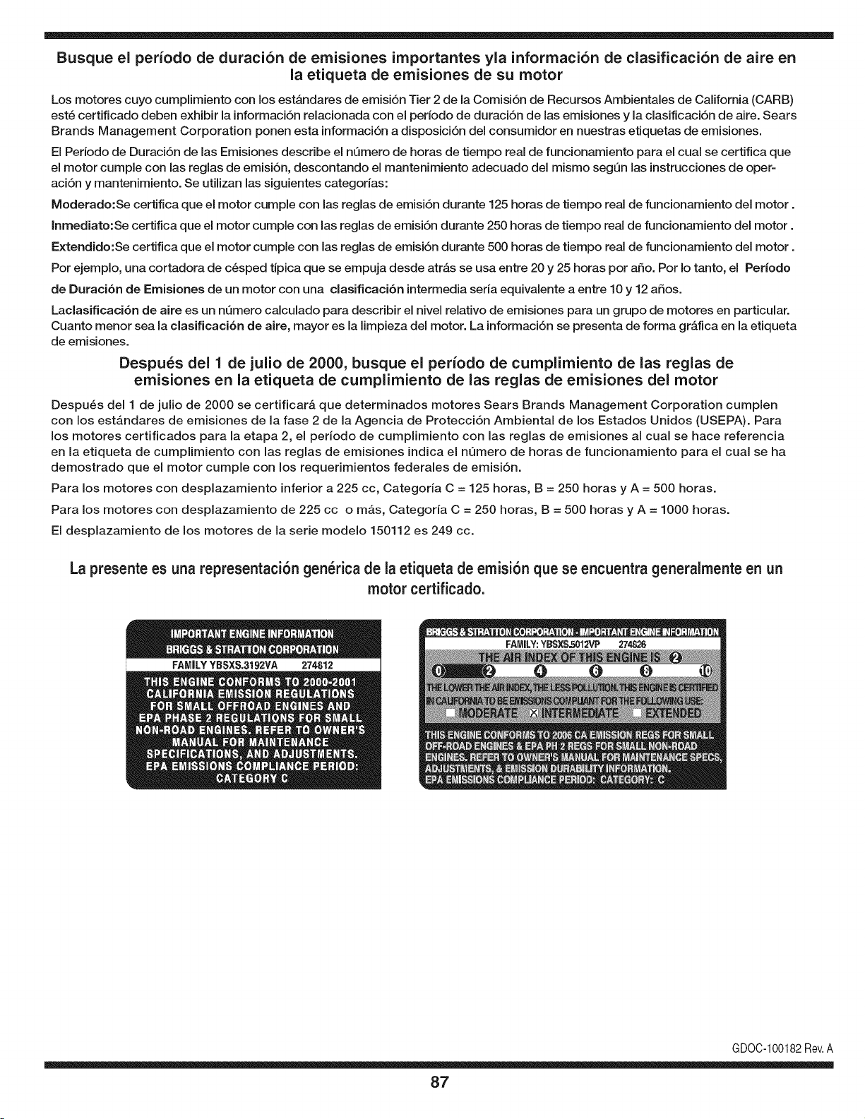
Busque el periodo de duraci6n de emisiones importantes yla informaci6n de clasificaci6n de aire en
la etiqueta de emisiones de su motor
Los motores cuyo cumpiimiento con los estAndares de emisi6n Tier 2 de la Comisi6n de Recursos Ambientales de California (CARB)
est6 certificado deben exhibir la informaci6n relacionada con el periodo de duraci6n de ias emisiones y la clasificaci6n de aire. Sears
Brands Management Corporation ponen esta informaci6n a disposici6n del consumidor en nuestras etiquetas de emisiones.
Ei Periodo de Duraci6n de las Emisiones describe el nQmero de horas de tiempo real de funcionamiento para el cuai se certifica que
el motor cumpie con ias reglas de emisi6n, descontando el mantenimiento adecuado del mismo segQn las instrucciones de oper-
aci6n y mantenimiento. Se utilizan las siguientes categonas:
Moderado:Se certifica que el motor cumpie con las reglas de emisi6n durante 125 horas de tiempo real de funcionamiento del motor.
Inmediato:Se certifica que el motor cumpie con las reglas de emisi6n durante 250 horas de tiempo real de funcionamiento del motor.
Extendido:Se certifica que el motor cumpie con las reglas de emisi6n durante 500 horas de tiempo real de funcionamiento del motor.
Por ejemplo, una cortadora de c6sped tJpica que se empuja desde arras se usa entre 20 y 25 horas por aSo. Por Io tanto, el Periodo
de Duraci6n de Emisiones de un motor con una clasificaci6n intermedia sena equivaiente a entre 10 y 12 aSos.
Laciasificaci6n de aire es un nQmero calculado para describir el nivel relativo de emisiones para un grupo de motores en particular.
Cuanto menor sea la clasificaci6n de aire, mayor es la limpieza del motor. La informaci6n se presenta de forma grAfica en la etiqueta
de emisiones.
Despu_s del 1 de julio de 2000, busque el periodo de cumplimiento de las reglas de
emisiones en la etiqueta de cumplimiento de las reglas de emisiones del motor
Despu6s del 1 de julio de 2000 se certificarA que determinados motores Sears Brands Management Corporation cumplen
con los estAndares de emisiones de la fase 2 de la Agencia de Protecci6n Ambientai de los Estados Unidos (USEPA). Para
los motores certificados para la etapa 2, el periodo de cumplimiento con ias reglas de emisiones al cual se hace referencia
en la etiqueta de cumplimiento con las reglas de emisiones indica el nQmero de horas de funcionamiento para el cual se ha
demostrado que el motor cumple con los requerimientos federales de emisi6n.
Para los motores con desplazamiento inferior a 225 cc, Categoria C = 125 horas, B = 250 horas y A = 500 horas.
Para los motores con desplazamiento de 225 cc o mAs, Categoria C = 250 horas, B = 500 horas y A = 1000 horas.
El desplazamiento de los motores de la serie modelo 150112 es 249 cc.
La presente es una representaci6n gen_rica de la etiqueta de emisi6n que se encuentra generaimente en un
motor certificado.
FAMILYYBSXS.3192VA 274812
GDOC-100182Rev.A
87
(Esta p_.ginase aplica s61oen EE.UU. y Canada.).
Sears Brands Management Corporation, el Consejo de Recursos Ambientales de California (CARB)
y la Agencia de Protecci6n Ambiental de los Estados Unidos (EPA)
Declaraci6n de garantia del sistema de control de emisiones (derechos y obligaciones de la garanfia de defectos del propi=
etario)
LA COBERTURADE LA GARANTJADECONTROLDE EMISIONESES Y PARALOSMODELOSCERTIFICADOSDELANO 1997YPOSTERIORES,
APLIOABLEA LOSMOTORESCERTIFICADOSCOMPRADOSENCALIFOR- QUESE COMPRENY UTILICENENCUALQUIERPARTEDE LOS ESTADOS
NIA EN1995Y POSTERIORMENTE,QUESE UTILIZANENCALIFORNIA, UNIDOS(Y A PARTIRDEL 1 DE ENERODE 2001 ENCANADA).
Declaraci6n de garanfia sobre defectos en el control de emJsiones para California y los Estados UnJdos
ElConsejode RecursosAmbientalesde California(CARB),la EPA(Agencia
de Protecci6nAmbientalde los EE.UU.)y Searstienenel gusto de explicarla
garantiadel sistemade control deemisionespara motoresdela_o 2000y para
elfuturo con relaci6na motorespeque_ostodo terreno(SORE).En California,
los nuevosmotorespeque_ostodo terrenodebenestar dise_ados,construidos
y equipadosparacumplirconlas rigurosasnormasanti-smogdelestado.En
el restodelos EstadosUnidos,losmotoresnuevostodoterrenode encendido
porchispacertificadosparael a_o 1997debencumplirest_ndaressimilares
establecidospot la EPA.Sears debegarantizarel sistemade control deemi-
sionesde su motorparalosperiodosde tiempoenumeradosa continuaci6n,
siemprequeno hayaabuso,negligenciao mantenimientoindebidode su
motortodoterrenopeque_o.Su sistemade controlde emisionespuedeincluir
piezastalescomoel carburador,el filtrode aire, elsistemade encendido,el
silenciadoryel conversorcatalitico.Tambienpuede incluirconectoresy otras
unidadesrelacionadascon lasemisiones.Dondeexistaunacondici6ncubierta
por la garantia,Searsreparar_su peque6omotortodo terrenosin costo alguno
incluyendodiagn6stico,piezasy manodeobra
Cobertura de la garantJa Sears para defectos en el control de emJsiones
Los motorestodo terrenopeque6osest_ngarantizadosenIo relativoalcontrol alas disposicionesque se indiquena continuaci6n.Si una parte desu motor
de emisionesparadefectosen piezasduranteun periodode dos a_os,sujeto cubiertapot la garanfiaes defectuosa,Sears reparar_o sustituir_dichaparte.
Responsabilidades del propietario en relacibn con la garantia
Comopropietariodel motortodo terrenopeque_o,Ud.es responsablede la
realizaci6ndel mantenimientorequeridoquese incluyeen las instrucciones
de operaci6ny mantenimiento.Searsrecomiendaquese conserventodoslos
recibosrelativosal mantenimientode su motortodoterrenopeque_o,pero
no pude denegarla garantiasimplementepor la faltade los mismos,o por su
incumplimientodel mantenimientoprogramatic.Comopropietariodel motor
peque_otodoterrenodebe saberque, sin embargo,Sears lepuedenegar
lacoberturade lagarantiasi su motortodoterrenopeque6oo una piezadel
mismohanfalladodebido a abuso,negligencia,mantenimientoindebidoo
a modificacionesno aprobadas.Ud.es responsablede presentarsu motor
todoterrenopeque6oa un distribuidorde serviciosSearsautorizadotan pronto
comoaparezcaun problema.Las reparacionesde la garantiasinconfiicto
debencompletarseen un plazode tiemporazonable,no superiora 30 dias.Si
tienealguna preguntarespectoa sus derechosy responsabilidadesreferentes
a lagarantia,debe contactarcon un representantede serviciosSears al 1--
800--469--4663.La garantiade emisioneses unagarantiapotdefectos.Los
defectosse juzgande acuerdocon elfuncionamientonormalde unmotor.La
garantiano est_relacionadacon unapruebade emisionesen uso.
Disposiciones de la garantJa Sears para defectos en el control de emJsiones
Las siguientesson disposicionesespecificasrelacionadascon la coberturade lagarantia paradefectosenel controlde emisiones.Esun a_adidoa lagarantiade
motorSearspara motoresno reguladosque seencuentraen lasinstruccionesde funcionamientoy mantenimiento.
1. Piezascon garantia
La coberturade esta garantiase extiendeL]nicamentealas piezas
queaparecena continuaci6n(las partesde lossistemasde controlde
emisiones),siempreque dichas piezasestuvieranya en el motoren el
momentode su compra.
a. Sistemade medici6nde combustible
• Sistema deenriquecimientoparaarranqueen frio
• Carburadory partesinternas
• Bombade combustible
b. Sistemade inducci6nde aire
• Filtrode aire
• Colector de admisi6n
c. Sistemadeencendido
• Bujia(s)de encendido
• Sistema deencendidomagneto
d. Sistemadelcatalizador
• Convertidorcatalitico
• Colector de escape
• Sistema deinyecci6nde aireo v_lvulade impulsos
e. Elementosvariadosusadosenlossistemasanteriores
• Wlvulas de vacio,sensiblesa temperatura,posici6ny tiempo
e interruptores
• Conectoresy montajes
2. AIcancede la cobertura
Searsgarantizaal poseedorinicialy a los compradoressubsiguientes
quelas piezascon garantiano tendr_ndefectosen materialesni mano
de obraque provoquenla falla de las mismasduranteun periodode
dos aSosa partirde la fechaen queel motorse entregaa un comprador
particular.
3. Sin cargo
La reparaci6no reemplazode cualquierpartecon garantia se realizar_
sin cargo algunoparael poseedor,incluyendotareasde diagn6sticoque
permitandeterminarsi una partecon garantiaes defectuosa,siempreque
dichodiagn6sticose realiceen un distribuidorde serviciosSearsautoriza-
do. Parael serviciode lagarantia deemisiones,contacteal distribuidorde
serviciosSearsautorizadom_s cercanoincluidoen las"P_ginasamarillas"
en lascategorias"Motores,gasolina","Motoresde gasolina","Podadoras
de cesped",o similares.
4. Reclamacionesy exclusionesa la cobertura
Las reclamacionesde lagarantia debenenviarsede acuerdocon las
disposicionesde la politica degarantia para motoresSears.La cobertura
de lagarantia excluir_defectosen piezascongarantia queno scan partes
originalesSears,o abuso,negligenciao mantenimientoincorrecto,tal y
como se estableceen lapolitica degarantia para motoresSears.Searsno
es responsablede lasfallas en piezascon garantia provocadaspor el uso
de partesa6adidas,que no scan originaleso quese hayan modificado.
5. Mantenimiento
Cualquierpartecon garantiaque no esteprogramadaparaset reempla-
zadacomo mantenimientorequerido,o que s61odeba inspeccionarse
regularmentealefecto de "inspeccioneo reemplacesegL]nsea necesario",
estar_garantizadacontradefectosduranteel periodode la garantia.Todas
las piezasgarantizadasqueesten programadaspara su reemplazopara
cumplir con los requisitosde mantenimientoestar_ngarantizadass61o
por el periodoanterioral primerreemplazoprogramaticparadicha pieza.
Cualquierpiezade recambioquesea equivalenteen funcionamientoy
durabilidadpuedeusarse pararealizarmantenimientoo reparaciones.El
propietarioes responsablede realizartodoel mantenimientorequerido,tal
y comose define en las instruccionesde funcionamientoy mantenimiento
Sears
6. Coberturaindirecta
Porla presente,la coberturase extiendea la falla de cualquiercomponente
de motorprovocadapot lafalla de unapiezacon garantiaque estetodavia
en periodode garantia.
En los EstadosUnidosy Canad_hay unalinea deatenci6nde 24 horas,1-800-469--4GG3,quecuentacon un menL]con mensajespre-grabadosque contienen
informaci6npara el mantenimientode motores.
DECLARACIONFEDERALy/oDECALIFORNIASOBRE GARANTJAS EN EL CONTROL DE EIVIISIONES
SUS DERECHOS Y OBLIGACIONES EN CUANTO A LA GARANTJA
MTDConsumerGroupInc, laAgencia deProtecci6nMedioambientalde los EstadosUnidos(EPA),y paraaquellosproductoscertificadosparasu ventaen el es-
tadode California,el Departamentode los Recursosdel Aire deCalifornia(CARB)secomplacenen explicarla garanfiaque cubre al sistemade control (ECS)de
emisiones(evaporativasy/o de escape)de su equipoy motor(motorde equipos deexteriores)deencendidopot chispaparatodo terreno,peque_o,de exteriores
del a_o2006 y a_osposterioresEn California,losnuevosmotoresde equiposde exterioresdebenestar dise_ados,construidosyequipadospara cumplircon las
estrictasnormasantipoluci6ndel Estado(en otrosestados,losequipos del a_o 1997y modelosposterioresdebenserestar dise_ados,construidosy equipados
para cumplircon las regulacionesde motoresde encendidopor chispapara todoterrenopeque_osde laAgencia de Protecci6nMedioambientalde los Estados
Unidos,(EPA).MTDConsumerGroupInc. debe garantizarel sistemade control de emisiones(ECS) de su motorde equiposde exteriorespot el periodode
tiempo indicadom_sabajo,siempreycuando no existauso incorrecto,negligenciao mantenimientoinadecuadode dicho motor.
Su ECSpuedeincluir piezastalescomo el carburador,el sistemade inyecci6nde combustible,el sistemade encendido,el convertidorcatalitico,losdep6sitos
de combustible,laslineas decombustible,lostaponesde combustible,lasv_lvulas, contenedores,filtros, manguerasde vapor,abrazaderas,conectoresyotros
componentesafinesrelacionadosconlasemisiones.
Dondeexista unacondici6ncubiertapor la garantia,MTDConsumerGroupInc. reparar_su motorde equiposde exterioressincostoalguno incluyendoel
diagn6stico,las piezasy la manode obra.
COBERTURA DE LA GARANTJA DEL FABRICANTE:
Este sistemade control deemisionesse garantizaporel t@minode dos aSos.Si alguna piezarelacionadacon lasemisionesde su motorde equiposde
exterioreses defectuosa,MTDCONSUMERGROUPINC.reparar_o sustituir_dicha pieza.
RESPONSABILIDADES DEL PROPIETARIO SEGUN LA GARANTJA:
En su car_cterde propietariodel motorde equipos deexteriores,usted es responsabledel mantenimientorequeridoquese especificaenel manualdel propieta-
rio.MTDConsumerGroupInc le recomiendaque conservetodos losrecibos quecubrenel mantenimientode su motor,no obstanteIo cual MTDConsumerGroup
Inc no podr_denegarel cumplimientode lagarantia Qnicamentepor lafalta de los recibos.
Comopropietariodel motorde equiposde exteriores,usteddebe saber queMTDConsumerGroup Inc.puededenegarlacoberturade lagarantia si su motoro
unapieza del mismofallan debidoa uso incorrecto,negligencia,mantenimientoindebidoo a modificacionesno aprobadas.
Ustedes responsablede presentarsu motoral centrode distribuci6no serviciotecnico de MTDConsumerGroupInc. tan prontocomo aparezcael problema.Las
reparacionescubiertaspor la garantiase debenIlevara caboen un lapso razonableque no excedade 30 dias. Sitiene algunapreguntarespectode lacobertura
de la garantia,p6ngaseen contactocon el Departamentodel ServicioT@nicode MTDConsumerGroupInc. al telefono1-800-800-7310o pot correoelectr6nico
en http://support.mtdproducts.com
COBERTURA DE LA GARANTJA DE EMISIONES GENERALES:
MTDConsumerGroupIncgarantizaal compradorfinal y a cadacompradorsubsiguienteque el motorde equiposde exteriores:est_ dise_ado,construidoy
equipadode modode cumplir contodas las regulacionesaplicablesy quese encuentralibrede defectosde materialesy de fabricaci6nque pudierencausar la
falla de una piezagarantizadaidentica,en todos losaspectos materialesa la piezadescriptaen la solicitudde certificaci6nde MTDConsumerGroupInc.
El periodode garantiacomienzaen la fechade entregadel motoral compradorfinal o en lafecha en que la m_quinase pone enfuncionamientopot primeravez.
El periodode garantiaes de dosaSos.
Sujetoa ciertas condicionesyexclusionesquese indicana continuaci6n,lagarantia delas piezasrelacionadascon lasemisioneses la siguiente:
1. Cualquierpiezagarantizadaque no esteprogramadapara serreemplazadacomo partedel mantenimientorequeridoen lasinstruccionesescritassuminis-
tradasse garantizaporel periodo de garantiaarriba mencionado.Sila piezafalla duranteel periodo de coberturade la garantia,la mismaser_ reparada
o reemplazadapor MTDConsumerGroupInc. de acuerdo conel parrafo(4) a continuaci6n.Cualquierpiezareparadao reemplazadasegQnlagaranfia se
garantizar_potel resto del periodode garantia.
2. Cualquierpiezagarantizadaqueeste programadasolamenteparainspecci6nregularen las instruccionesescritassuministradassegarantiza potel periodo
de garantiaarribamencionado.Cualquierpiezareparadao reemplazadasegQnla garantiase garantizar_pot el restodel periodo.
3. Cualquierpiezagarantizadaqueeste programadapara reemplazosegQnel mantenimientorequeridode conformidadcon lasinstruccionesescritassuminis-
tradas,se garantizaporel periodode tiempoanteriora laprimerafecha de reemplazoprogramadapara esapieza.Si la piezafalla antes del primerreemplazo
programatic,la mismaser&reparadao reemplazadapot MTDConsumerGroupInc. de acuerdocon el parrafo(4) a continuaci6n.Cualquierpiezareparadao
reemplazadabajogarantia se garantizar_potel resto del periodoanterioral primerreemplazoprogramaticpuntualparaesa pieza.
4. La reparaci6no el reemplazode cualquierpieza garantizadadeconformidadcon lasdisposicionesde lagarantia queaquise estipulase deben realizarenun
centrode garantiasin costoalguno parael propietario.
5. Noobstantelas disposicionesque aquise estipulan,losservicioso reparacionesbajo garantiase suministrar_nen todos nuestroscentrosde distribuci6nbajo
franquiciademantenimientoparalos motoreso equiposen cuesti6n.
6. El propietariodel motorde equiposdeexterioresno deber_pagarel trabajode diagn6sticodirectamenteasociadocon unapiezagarantizadadefectuosaen
relaci6ncon las emisiones,siemprey cuandodicho trabajode diagn6sticose realiceen uncentrocubiertopot lagarantia.
7. MTDConsumerGroup Inces responsablepotdaSoscausadosa otros componentesde motoreso equipos derivadosde lafalla bajo garantiade cualquier
piezagarantizada.
8. Durantelatotalidaddelperiododegarantiadelmotoryequipoparatodoterrenoarribamencionado,MTDConsumerGroupIncmantendr_unsuministro
depiezasbajogarantiasuficienteparasatisfacerlademandaesperadadetalespiezas.
9. Cualquierpiezadereemplazosepodr_usarparaelcumplimientodelmantenimientoolasreparacionesbajogarantiaysesuministrar_nsincargopara
elpropietario.Dichousonoreducir_lasobligacionesdegarantiadeMTDConsumerGroupInc.
10.Nosepodr_nusarpiezasadicionalesnimodificadasquenoestenexentasdeacuerdoconelDepartamentodelosRecursosdelAire(AirResourcesBoard).
Elusodecualquierpiezaadicionalomodificadanoexentaporelcompradorfinalser_causaldeinvalidezdelosreclamosbajogaranfia.MTDConsumer
GroupIncnotendr_responsabilidadpotlagarantiadefallasdepiezasgarantizadasquefuerencausadaspotelusodeunapiezaadicionalnoexenta
omodificada.
PIEZAS GARANTIZADAS:
La reparaci6no el reemplazode cualquierpiezagarantizadaquede otto modopudieseestar cubiertapor lagarantia podr_set excluidade tal coberturade
garantiasi MTDConsumerGroupIncdemuestraqueel motores objeto de usoincorrecto,negligenciao mantenimientoinadecuado,y que tal usoincorrecto,
negligenciao mantenimientoinadecuadofuecausa directade la necesidadde reparaci6no reemplazode dichapieza.NoobstanteIo antedicho,cualquierajuste
de uncomponentecon un dispositivode limitaci6nde ajusteinstaladoen f_bricay quefuncioneadecuadamente,podr_set cubiertopot la garantia.Adem_s,
la coberturabajoesta garantiase extiendesolo a piezas queestuvieronpresentesen el motory equipotodo terrenoadquiridos.
Est_ncubiertaslas siguientespiezascon garanfia paraemisiones(decorresponder):
(1) Sistemade medici6nde combustible
• Sistemade mejorapara inicioen frio (cebadosuave)
• Carburadory piezasinternas(osistemade inyecci6npotcombustible)
• Bombade combustible
• Dep6sitode combustible
(2) Sistemade inducci6nde aire
• Purificadordeaire
• Colectordeadmisi6n
(3) Sistemade encendido
• Bujia(s) deencendido
• Sistemade encendidopot magneto
(4) Sistemade encendido
• Convertidorcatalitico
,, SAI (v_lvula Reed)
(5) Componentesvariosutilizadosen el sistemaanterior
• Wlvulas e interruptoresde vacio,temperatura,posici6nsensiblesal tiempo
• Conectoresy montajes
(6) Controlevaporativo
• Manguerade combustible
• Abrazaderasde la manguerade combustible
• Tap6ndel combustibleatado pot correa
• Cajadecarbono
• Lineas de vapor
GDOC-100223

Felicitaciones por haber realizado una adquisici6n inteligente. El producto Craftsman® que ha
adquirido esta diseSado y fabricado para brindar muchos aSos de funcionamiento confiable. Pero
como todos los productos a veces puede requerir de reparaciones. Es en ese momento cuando el
disponer de un Acuerdo de protecci6n para reparaciones le puede ahorrar dinero y problemas.
A continuaci6n se detallan los puntos incluidos en el Acuerdo:
[] Servicio experto prestado por nuestros 10,000 especialistas en reparaciones profesionales
[] Servicio ilirnitado sin cargo para las piezasy la mano de obra en todas las reparacionescubiertas
[] Reernplazo del producto hasta 1500 d61aressi no es posible reparar el producto cubierto
[] Descuento de 25% del precio normal del servicio y de las piezas relacionadas con el mismo que no esten cubiertas
por el acuerdo; ademas, 25% del precio normal de la verificaci6n de mantenimientopreventivo
[] Ayuda r_pida pot tel_fono - Io IlamamosResoluci6n RApida- el apoyo telef6nico de un Chamusca al representante.
Piense en nosotros como el manual "de un dueSo hablador."
Una vez adquirido el Acuerdo, puede programar el servicio con tan s61orealizar una Ilamadatelef6nica. Puede Ilamar en
cualquier momento del dia o de la noche o programar un servicio en linea.
ElAcuerdo de Protecci6nde Reparaci6nes una compra sin riesgo. Si usted anula por alguna raz6n durante el periodo de
garantia de producto, proporcionaremos un reembolso Ileno.O, un reembolso prorrateado en cualquier momentodespues
del periodo de garantia de producto expira, iAdquiera hoy su acuerdode protecci6n para reparaciones!
Se aplican determinadas limitaciones y exclusiones. Para obtener informaciTn adicional y precios en los Estados
Unidos Ilame al 1-800-827-6655.
El *Coverage en Canad_ivaria en algunos articulos. Para detalles Ilenos la Ilamada Chamusca Canad_ien 1-800-
361-8885.
Servicio de instalaci6n de Sears
Si desea solicitar la instalaci6n profesionalde Sears de aparatos domesticos, dispositivos paraabrir portones, calentado-
res de agua y otros articulos domesticos importantes, en los Estados Unidos o Canada flame al 1-800-4-MY-HOME®.
91

Riding Equipment
questions or problems?
Satisfaction with your purchase
is our number one concern!
To troubleshoot problems,
get answers to questions, order parts,
or schedule repair service for your
Riding Equipment, call the number below.
Para respuestas a preguntas o problemas,
y ordenar piezas o pedir servicio para la
reparacibn de su equipo, Ilame el nt_mero abajo.
1-800-659-5917
Craftsman Help Line
www.craftsman.com
TM
® Registered Trademark / Trademark of KCD IP, LLC in the United States, or Sears Brands, LLC in other countries
® Marca Registrada / TMMarca de Fabrica de KCD IP, LLC en Estados Unidos, o Sears Brands, LLC in otros paises


