
flf_EUEVASLt S TAR TtNG E A S E TM
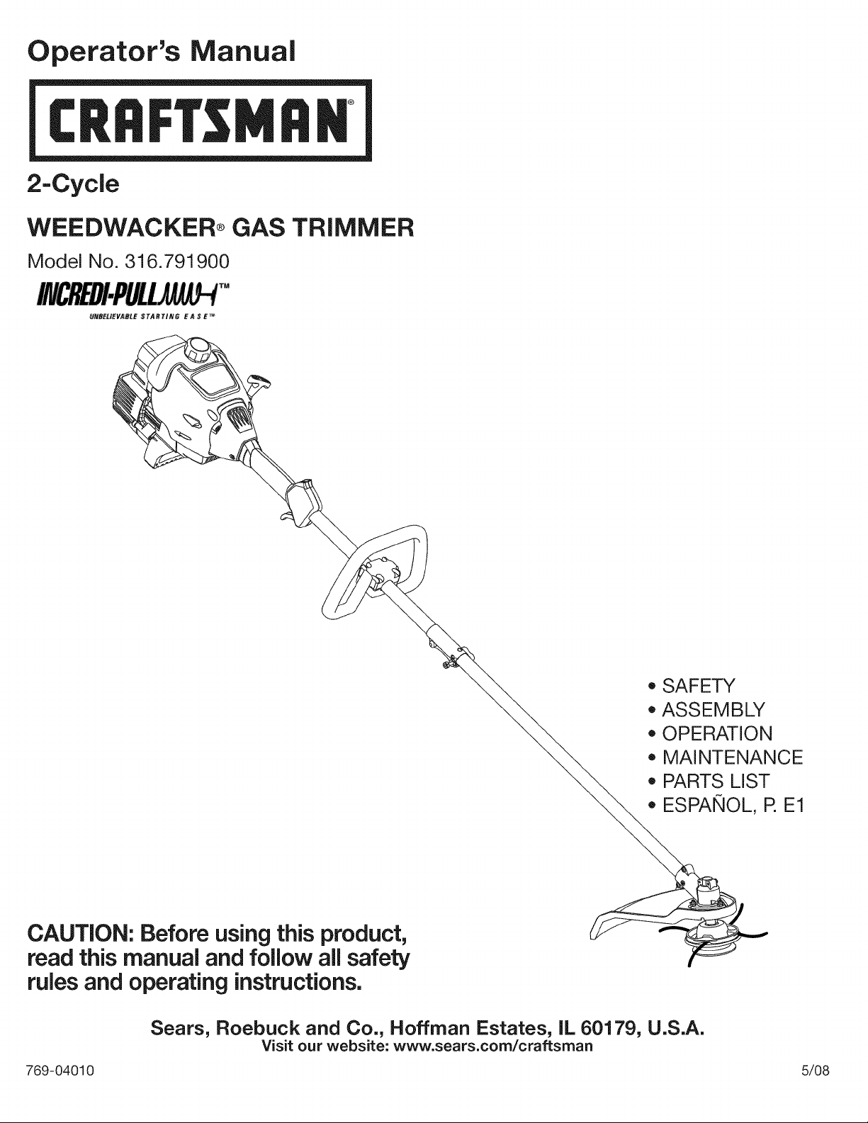
* SAFETY
* ASSEMBLY
* OPERATION
* MAINTENANCE
* PARTS LIST
* ESPANOL, R E1
CAUTION: Before using this product,
read this manual and follow all safety
rules and operating instructions.
Sears, Roebuck and Co., Hoffman Estates, IL 60179, U.S.A.
Visit our website: www.sears.corn/craftsrnan
769-04010 5/08
CALiFORNiA PROPOSiTiON 65 WARNING All information, illustrations, and specifications in this manual are based
THE ENGINE EXHAUST FROM THIS PRODUCT CONTAINS
CHEMICALS KNOWN TO THE STATE OF CALiFORNiA TO CAUSE
CANCER, BIRTH DEFECTS OR OTHER REPRODUCTIVE HARM.
TABLE OF CONTENTS
Safety Rules .......................................... 2
Warranty ............................................. 4
Know Your Unit ........................................ 4
Assembly Instructions ................................... 4
Oil and Fuel Information ................................. 5
Starting/Stopping Instructions ............................ 5
Operating Instructions ................................... 6
Maintenance and Repair Instructions ....................... 6
Cleaning and Storage ................................... 8
Troubleshooting Chart ................................... 9
Specifications ........................................ 10
Parts List ........................................... E14
Service Numbers .............................. Back Cover
SPARK ARRESTOR NOTE
NOTE: For users on U.S. Forest Land and in the states of California,
Maine, Oregon and Washington. All U.S. Forest Land and the state of
California (Public Resources Codes 4442 and 4443), Oregon and
Washington require, by law that certain internal combustion engines
operated on forest brush and/or grass-covered areas be equipped with a
spark arrestor, maintained in effective working order, or the engine be
constructed, equipped and maintained for the prevention of fire. Check
with your state or local authorities for regulations pertaining to these
requirements. Failure to follow these requirements could subject you to
liability or a fine. This unit is factory equipped with a spark arrestor. If
it requires replacement, ask your LOCAL SERVICE DEALER to install the
Accessory Part #753-05169 Muffler Assembly.
on the latest product information available at the time of printing. We
reserve the right to make changes at any time without notice.
The purpose of safety symbols is to attract your attention to possible
dangers. The safety symbols, and their explanations, deserve your
careful attention and understanding. The safety warnings do not by
themselves eliminate any danger. The instructions or warnings they
give are not substitutes for proper accident prevention measures.
SYMBOL MEANING
SAFETY ALERT: indicates danger, warning or caution.
Attention is required in order to avoid serious personal
injury. May be used in conjunction with other symbols or
pictographs.
NOTE: Advises you of information or instructions vital to the
operation or maintenance of the equipment.
DANGER: Failure to obey a safety warning will result in
| serious injury to yourself or to others. Always follow the
safety precautions to reduce the risk of fire, electric shock
and personal injury.
WARNING: Failureto obey a safety warning can result in
injury to yourself and others. Always follow the safety precautions
to reduce the risk of fire, electric shock and personal injury.
CAUTION: Failure to obey a safety warning may result in
property damage or personal injury to yourself or to others.
Always follow the safety precautions to reduce the risk of fire
electric shock and personal injury.
Read the Operator's Manual and follow all warnings and safety
instructions. Failure to do so can result in serious injuryto the operator
and/or bystanders.
FOR QUESTIONS, CALL 1-800-659-5917
= IMPORTANT SAFETY INSTRUCTIONS =
READ ALL INSTRUCTIONS BEFORE OPERATING
[____J ARNING: When using the unit, you must follow the safety
rules. Please read these instructions before operating the unit in
order to ensure the safety of the operator and any bystanders.
Please keep these instructions for later use.
• Read the instructions carefully. Be familiar with the controls and
proper use of the unit.
Do not operate this unit when tired, ill or under the influence of
alcohol, drugs or medication.
Children must not operate the unit. Teens must be accompanied
and guided by an adult.
Inspect the unit before use. Replace damaged parts. Check for
fuel leaks. Make sure all fasteners are in place and secure.
Replace cutting attachment parts that are cracked, chipped or
damaged in any way.
Use only Hassle FreeTM XTRA QUIET Spiral Line. Never use
metal-reinforced line, wire, chain or rope. These can break off
and become dangerous projectiles.
Be aware of risk of injury to the head, hands and feet.
Clear the area to be cut before each use. Remove rocks, broken
glass, nails, wire, string and other objects which may be thrown
or become entangled in the cutting attachment. Clear the area of
children, bystanders and pets; keep them outside a 50-foot
(15 m) radius, at a minimum. Even then, they are still at risk from
thrown objects. Encourage bystanders to wear eye protection. If
you are approached, stop the unit immediately.
Squeeze the throttle control and check that it returns
automatically to the idle position. Make all adjustments or repairs
before using the unit.
FUEL SAFETY WARNINGS
A I WARNING: Gasoline is highly flammable and its vapors i
I _lb I can exp ode f gn ted. Take the fo ow ng precaut ons:
Store fuel only in containers specifically designed and approved
for the storage of such materials.
Always stop the engine and allow it to cool before filling the fuel
tank. Never remove the fuel tank cap or add fuel when the engine is
hot. Never operate the unit without the fuel cap securely in place.
Loosen the fuel tank cap slowly to relieve any pressure in the tank.
Mix and add fuel in a clean, well-ventilated outdoor area where
there are no sparks or flames. Remove the fuel cap slowly, and
only after the engine stops. Do not smoke while fueling or mixing
fuel. Wipe up any spilled fuel from the unit immediately.
Avoid creating a source of ignition for spilled fuel. Do not start the
engine until fuel vapors dissipate.
Move the unit at least 30 feet (9.1 m) from the fueling source and site
before starting the engine. Do not smoke. Keep sparks and open
flames away from the area while adding fuel or operating the unit.
WHILE OPERATING
= Never start or run the unit inside a closed room or building.
Breathing exhaust fumes can be fatal. Operate this unit only in a
well-ventilated outdoor area.
Wear safety glasses or goggles that meet ANSi Z87.1-1989 standards
and are marked as such. Wear ear/hearing protection when operating
this unit. Wear a face or dust mask if the operation is dusty.
Wear heavy long pants, boots, gloves and a long sleeve shirt. Do
not wear loose clothing, jewelry, short pants, sandals or go
barefoot. Secure hair above shoulder level.
• Thecuttingattachmentshieldmustalwaysbeinplacewhile • Turntheenginetooffanddisconnectthesparkplugfor
operatingtheunit.Donotoperateunitwithoutbothtrimminglines
extended,andtheproperlineinstalled.Donotextendthe
trimminglinebeyondthelengthoftheshield.
Thisunithasaclutch.Thecuttingattachmentremainsstationary
whentheengineisidling.Ifitdoesnot,taketheunittoaSearsor
otherqualifiedservicedealerforanadjustment.
AdjusttheD-handletoyoursizeinordertoprovidethebestgrip.
Besurethecuttingattachmentisnotincontactwithanything
beforestartingtheunit.
Usetheunitonlyindaylightorgoodartificiallight.
Avoidaccidentalstarting.Beinthestartingpositionwhenever
pullingthestarterrope.Theoperatorandunitmustbeinastable
positionwhilestarting.RefertoStarting/StoppingInstructions.
Usetherighttool.Onlyusethistoolforitsintendedpurpose.
Alwaysholdtheunitwithbothhandswhenoperating.Keepafirm
griponbothhandlesorgrips.
Keephands,face,andfeetawayfromallmovingparts.Donot
touchortrytostopthecuttingattachmentwhenitrotates.
Donottouchtheengine,gearhousingormuffler.Thesepartsget
extremelyhotfromoperation,evenaftertheunitisturnedoff.
Donotoperatetheenginefasterthanthespeedneededtocut,trim
oredge.Donotruntheengineathighspeedwhennotcutting.
Alwaysstoptheenginewhencuttingisdelayedorwhenwalking
fromonecuttinglocationtoanother.
Ifyoustrikeorbecomeentangledwithaforeignobject,stoptheengine
immediatelyandcheckfordamage.Donotoperatebeforerepairing
damage.Donotoperatetheunitwithlooseordamagedparts.
maintenanceorrepair.
Useonlyreplacementpartsoraccessoriesrecommendedforthis
toolthataredistributedbySearsoraCraftsmanoutlet.Useof
anyreplacementpartsoraccessoriespurchasedelsewheremay
behazardous,andwillalsovoidyourwarranty.
Keepunitcleanofvegetationandothermaterials.Theymay
becomelodgedbetweenthecuttingattachmentandshield.
Toreducefirehazard,replaceafaultymufflerandsparkarrestor.
Keeptheengineandmufflerfreefromgrass,leaves,excessive
greaseorcarbonbuildup.
OTHERSAFETYWARNINGS
Neverstoretheunitwithfuelinthetank,insideabuildingwhere
fumesmayreachanopenflame(pilotlights,etc.)orsparks
(switches,electricalmotors,etc.).
Allowtheenginetocoolbeforestoringortransporting.Besureto
securetheunitwhiletransporting.
Storetheunitinadryplace,securedorataheighttoprevent
unauthorizeduseordamage.Keepoutofthereachofchildren.
Neverdouseorsquirttheunitwithwateroranyotherliquid.Keep
handlesdry,cleanandfreefromdebris.Cleanaftereachuse,see
CleaningandStorageinstructions(p.8).
Keeptheseinstructions.Refertothemoftenandusethemto
instructotherusers.Ifyouloanthisunittoothers,alsoloanthem
theseinstructions.
SAVE THESE INSTRUCTIONS
,, SAFETY & INTERNATIONAL SYMBOLS ,,
This operator's manual describes safety and international symbols and pictographs that may appear on this product. Read the operator's
manual for complete safety, assembly, operating and maintenance and repair information.
SYMBOL MEANING SYMBOL MEANING
I _ ,, SAFETY ALERT SYMBOL
A _t_ Indicates danger, warning or CaUtion: May be Used
_[ conjunction with other symbols or pictographs.
i
mREAD OPERATOR'S MANUAL
WARNING: Read the operat0r;s manuai(s)and
follow aHwarnings and safety instructions, Failure to
do so can result in serious injury to the operator
and/or bystandersl
_,WEAR EYE AND HEARING PROTECTION
WARNING: _r0wn 0bj_ts and loud noisecan cause
severe eye injury and hearing loss.Wear eye protection
meeting ANSI Z87:14 989 standards and ear protection when
operating this unit. Use a fullface shield when needed.
= THROWN OBJECTS AND ROTATING CUTTER CAN
CAUSE SEVERE INJURY
WARNING: Small objects can be propelled at high
speed, causing injury. Keep away from the rotating rotor.
_. KEEP BYSTANDERS AWAY
_;;;_ I WARNING: Keepall bystanders,especially'children
__ and pets. at least 50 feet (15 m.) from the operating area.
_' HOT SURFACE I
,_ WARNING: Do not touch a hot muffler or cylinder.
I
You may get burned. These parts get extremely hot
, from operation. When turned off they remain hot for a
short time.
Z61L
ofo I
R
8 I Refer to operator's manual for the proper type
_1" PR,MER BULB I
• SHARP BLADE
.._1 WARNING: Sharp blade on cutting attachment shield.
-_ _ To prevent serious injury, do not touch the line cutting blade.
3
CRAFTSMAN FU LL WAR RANTY
If this Craftsman product fails due to a defect in material or workmanship within two years from the date of purchase, return it to any Sears
store, Parts & Repair Service Center, or other Craftsman outlet in the United States for free repair (or replacement if repair proves impossible).
This warranty applies for only 90 days from the purchase date if this product is ever used for commercial or rental purposes.
This warranty covers ONLY defects in material and workmanship. Sears will NOT pay for:
• Expendable items that can wear out from normal use within the warranty period, such as cutting line, filters or spark plugs.
• Repairs necessary because of accident or failure to operate or maintain the product according to all supplied instructions.
• Preventive maintenance, or repairs necessary due to improper fuel mixture, contaminated or stale fuel.
This warranty gives you specific legal rights, and you may also have other rights which vary from state to state.
Sears, Roebuck and Co., Hoffman Estates, IL 60179
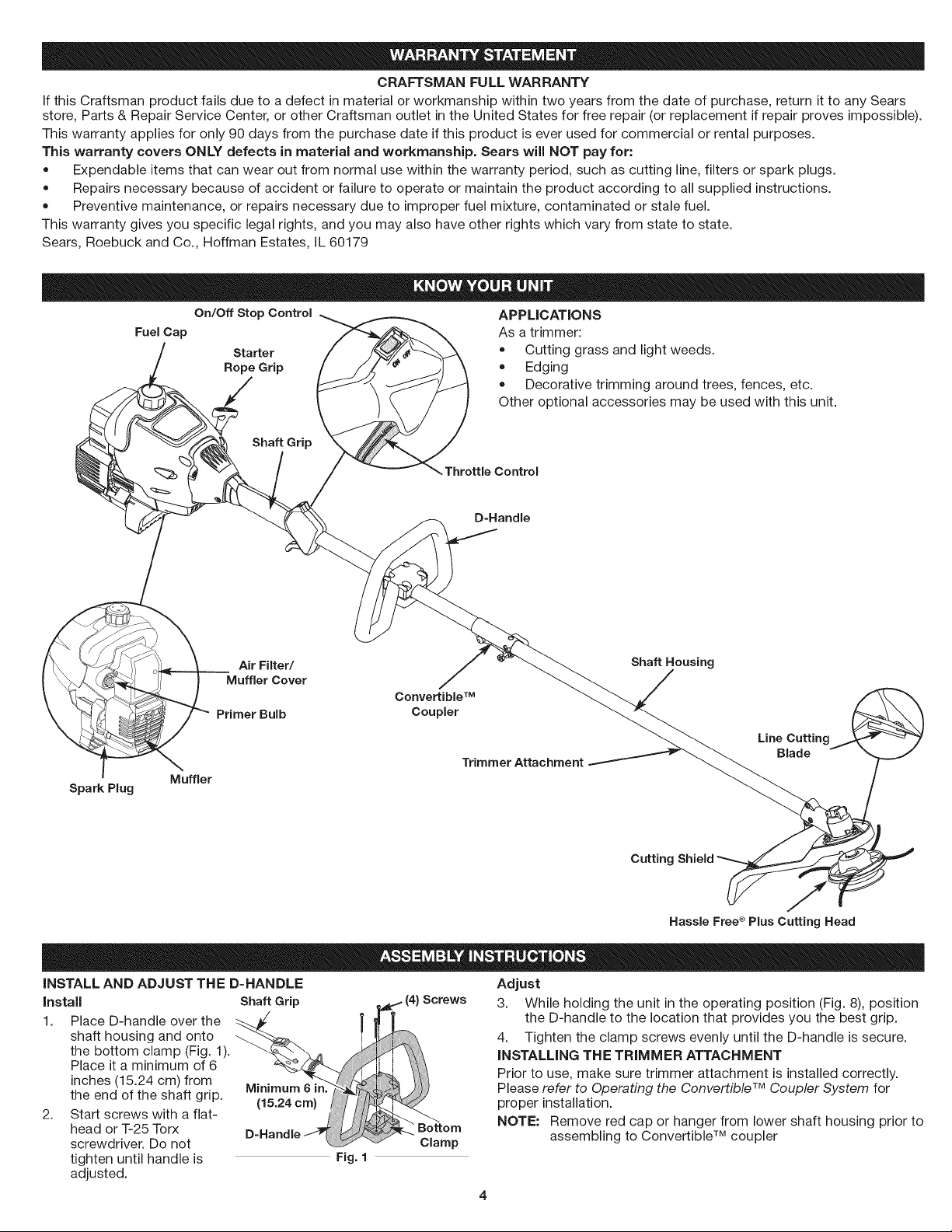
On/Off Stop Control APPLiCATiONS
Fuel Cap As a trimmer:
Starter • Cutting grass and light weeds.
Rope Grip • Edging
• Decorative trimming around trees, fences, etc.
Other optional accessories may be used with this unit.
Shaft Grip
, Throttle Control
D-Handle
Spark Plug
Muffler
Air Filter/ Shaft Housing
Muffler Cover
Convertible TM
Primer Bulb Coupler
Trimmer Attachment
Cutting Shield
J
Hassle Free<">Plus Cutting Head
iNSTALL AND ADJUST THE D-HANDLE
Install Shaft Grip
1. Place D-handle over the T
shaft housing and onto _
T
the bottom clamp (Fig. 1).
Place it a minimum of 6
inches (15.24 cm) from
the end of the shaft grip.
2. Start screws with a flat-
head or T-25 Torx
screwdriver. Do not
tighten until handle is Fig. 1
adjusted.
Minimum 6 in.
(15.24 cm)
Screws
Clamp
Adjust
3. While holding the unit in the operating position (Fig. 8), position
the D-handle to the location that provides you the best grip.
4. Tighten the clamp screws evenly until the D-handle is secure.
INSTALLING THE TRIMMER ATTACHMENT
Prior to use, make sure trimmer attachment is installed correctly.
Please refer to Operating the Convertible TM Coupler System for
proper installation.
NOTE: Remove red cap or hanger from lower shaft housing prior to
assembling to Convertible TM coupler
OILANDFUELMIXINGINSTRUCTIONS
Oldand/orimproperlymixedfuelarethemainreasonsfortheunitnot
runningproperly.Besuretousefresh,cleanunleadedfuel.Followthe
instructionscarefullyfortheproperfuel/oilmixture.
Definition of Blended Fuels
Today's fuels are often a blend of gasoline and oxygenates such as
ethanol, methanol, or MTBE (ether). Alcohol-blended fuel absorbs
water. As little as 1% water in the fuel can make fuel and oil
separate. It forms acids when stored. When using alcohol-blended
fuel, use fresh fuel (less than 60 days old).
Using Blended Fuels
If you choose to use a blended fuel, or its use is unavoidable, follow
recommended precautions:
• Always use the fresh fuel mix explained in your operator's manual
• Always agitate the fuel mix before fueling the unit
• Drain the tank and run the engine dry before storing the unit
Using Fuel Additives
The bottle of 2-cycle oil that came with your unit contains a fuel
additive which will help inhibit corrosion and minimize the formation of
gum deposits. It is recommended that you use our 2-cycle oil with this
unit. If unavailable, use a good 2-cycle oil de-signed for air-cooled
engines along with a fuel additive, such as STA-BIL_">Gas Stabilizer or
an equivalent. Add 0.8 oz. (23 ml.) of fuel additive per gallon of fuel
according to the instructions on the container. NEVER add fuel
additives directly to the unit's fuel tank.
I _ _CAUTION: For proper engine operation and maximum
reliability, pay strict attention to the oil and fuel mixing
instructions on the 2-cycle oil container. Using improperly
mixed fuel can severely damage the engine.
Thoroughly mix the proper ratio of 2-cycle engine oil with unleaded
gasoline in a separate fuel can. Use a 40:1 fuel/oil ratio. Do not mix
them directly in the engine fuel tank. See the table below for
specific gas and oil mixing
ratios.
NOTE: One gallon (3.8 liters)
of unleaded gasoline
mixed with one 3.2
oz. (95 ml.) bottle of
2-cycle oil makes a
40:1 fuel/oil ratio.
NOTE: Dispose of the old
fuel/oil mix in
accordance to
Federal, State and
Local regulations.
UNLEADED GAS 2 CYCLE OiL
1 GALLON US 3.2 FL. OZ.
(3.8 LITERS} (95 ml}
1 LITER 25 ml
MIXING fiATi6 -40il
WARNING: Gasoline is extremely flammable, ignited
vapors may explode. Always stop the engine and allow it
to cool before filling the fuel tank. Do not smoke while
filling the tank. Keep sparks and open flames at a distance
from the area.
WARNING: Remove fuel cap slowly to avoid injury from
fuel spray. Never operate the unit without the fuel cap
securely in place.
WARNING: Add fuel in a clean, well ventilated outdoorarea. Wipe up any spilled fuel immediately. Avoid creating
a source of ignition for spilt fuel. Do not start the engine
until fuel vapors dissipate.
WARNING: Operate this unit only in a well-ventilatedoutdoor area. Carbon monoxide exhaust fumes can be
lethal in a confined area.
WARNING: Avoid accidental starting. Make sure you are
in the starting position when pulling the starter rope (Fig. 4).
To avoid serious injury, the operator and unit must be
in a stable position while starting.
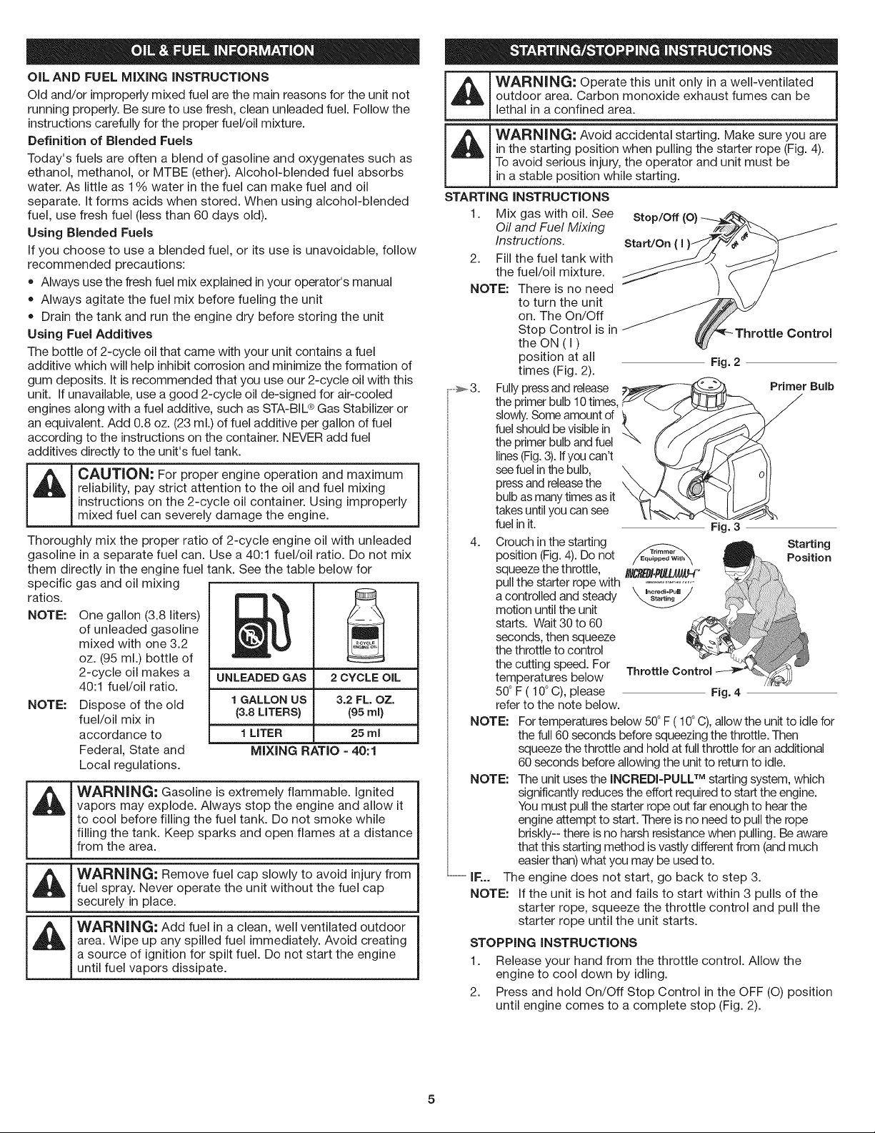
STARTING INSTRUCTIONS
1. Mix gas with oil. See Stop/Off (O} ___,_,_
Oil and Fuel Mixing /_-_Y'/OL_
Instructions.
2. Fill the fuel tank with
the fuel/oil mixture.
NOTE: There is no need
to turn the unit
on. The On/Off
Stop Control is in _ _Yi'qF- Throttle Control
the ON (I) y.f
_3.
4,
position at all
times (Fig. 2).
Fully pressand release
the primer bulb 10 times
slowly. Some amount of
fuel should be visiblein
the primer bulb and fuel
lines(Fig.3). Ifyou can't
see fuel in the bulb,
pressand releasethe
bulb as many times as it
takes until you can see
fuel in it.
Crouch inthe starting
position (Fig.4). Do not
squeeze the throttle, INflRR_.pUIL4_N..
pull the starter rope with
a controlled and steady
motion until the unit
starts. Wait 30 to 60
seconds, then squeeze
the throttle to control
the cutting speed. For
temperatures below
50° F ( 10°C), please
refer to the note below.
NOTE:
NOTE:
Fig. 2
Primer Bulb
Fig. 3
Starting
Position
Fig. 4
For temperatures below 50° F ( 10° C), allow the unit to idle for
the full 60 seconds before squeezing the throttle. Then
squeeze the throttle and hold at full throttle for an additional
60 seconds before allowing the unit to return to idle.
The unit uses the INCREDI=PULL TM starting system, which
significantly reduces the effort required to start the engine.
You must pull the starter rope out far enough to hearthe
engine attempt to start. There is no need to pull the rope
briskly-- there is no harsh resistance when pulling. Be aware
that this starting method is vastly different from (andmuch
easier than) what you may be used to.
The engine does not start, go back to step 3.
If the unit is hot and fails to start within 3 pulls of the
starter rope, squeeze the throttle control and pull the
starter rope until the unit starts.
STOPPING INSTRUCTIONS
1. Release your hand from the throttle control. Allow the
engine to cool down by idling.
2. Press and hold On/Off Stop Control in the OFF (O) position
until engine comes to a complete stop (Fig. 2).
5

OPERATINGTHE CONVERTIBLE TM COUPLER SYSTEM
WARNING: Before you begin using any attachment, read i
and understand the manual that came with the attachment.
mFollow all safety information contained within.
CAUTION: These attachments are to be snapped into I
the primary hole only. Using the wrong hole could lead to
Ipersonal injury or damage to the unit.
The Convertible TM coupler system enables the use of these optional
attaachments.
• Edger
Cultivator
Turbo Blower
Brushcutter
Pole Saw
Blade Pruner
Hedge Trimmer
REMOVING THE TRIMMER ATTACHMENT OR OTHER ATTACHMENT
_ WARNING: To avoid serious personal injury and i
damage to the unit, shut the unit off before removing or
Jinstalling all attachments.
1. Turn the knob
counterclockwise to
loosen (Fig. 7).
2. Press and hold the
release button (Fig. 5).
3. While firmly holding the
upper shaft housing, pull
the trimmer attachment or
other attachment straight
out of the Convertible TM
coupler (Fig. 6).
Convertible TM Release Button
Guide Recess
Fig. 5
iNSTALLiNG THE TRIMMER ATTACHMENT OR OTHER ATTACHMENT
_ CAUTION: Before operating this unit, be sure that the
release button is fully snapped into the primary hole (Fig. 6),
J
and that the knob (Fig. 7) is securely tightened.
NOTE: To make installing or Primary Hole
removing the
attachment easier, _ __ __,,
place the unit on the
ground or on a work
bench. _ ,_
1. Turn knob
counterclockwise to Upper Shaft Lower Shaft
loosen (Fig. 7). Housing
2. While firmly holding the Housing
trimmer attachment or Fig. 6
other attachment, push it 90° Edging Hole
straight into the (Trimmer Only)
Convertible TM coupler
until the release button
snaps firmly into the
primary hole (Fig. 6).
NOTE: Aligning the release
button with the guide
recess will help Knob
installation (Fig. 5). Fig. 7
3. Turn the knob clockwise
to tighten (Fig. 7).
For decorative edging with the line head trimmer attachment or
other attachment, lock the release button of the attachment into the
90 ° hole (Fig. 7).
HOLDING THE TRIMMER
I A I WARNING: Always wear eye, hearing, foot and body i
protection to reduce the risk of injury when operating this unit. J
Before operating the unit, stand in the operating position (Fig. 8).
Check for the following:
The operator is wearing eye
protection and proper clothing
With a slightly-bent right arm, the
operator's hand is holding the shaft grip
The operator's left arm is slightly bent,
the left hand holding the D-handle
The unit is at waist level
The trimmer attachment is parallel to
the ground and easily contacts the
grass without the need to bend over
TIPS FOR BEST TRIMMING RESULTS
= Keep the trimmer attachment parallel _'_
to the ground. _u_,_
• Cut from left to right whenever possible. Fig. 8
Cutting to the right improvesthe unit's
cutting efficiency. Clippings are thrown away from the operator.
Trim only when grass and weeds are dry.
The life of your cutting line is dependent upon:
Following the trimming tips
- What vegetation is being cut
- Where vegetation is being cut
o
DECORATIVE TRiMMiNG 30/o__
Decorative trimming is accomplished by
removing all vegetation around trees,
posts, fences and more. Rotate the
whole unit so that the trimmer
attachment is at a 30 ° angle to the ground (Fig. 9).
Fig. 9
MAINTENANCE SCHEDULE
WARNING: To prevent serious injury, never perform
I _ I maintenance or repairs with unit running. Always service
I -- I and repair a cool unit. Disconnect the spark plug wire to
ensure that the unit cannot start.
Perform these required maintenance procedures at the frequency
stated in the table. These procedures should also be a part of any
seasonal tune-up.
NOTE: Some maintenance procedures may require special tools or
skills. If you are unsure about these procedures take your unit to
Sears or other qualified service dealer. Call 1=8004=MY=HOME®
for more information.
NOTE: Maintenance, replacement, or repair of the emission
control devices and system may be performed by a Sears
or other qualified service dealer. Call 1-800-4-MY-HOME ®
for more information.
In order to assure peak performance of your engine, inspection of the
engine exhaust port may be necessary after 50 hours of operation. If
you notice lost RPM, poor performance or general lack of acceleration,
this service may be required. If you feel your engine is in need of this
inspection, refer service to a Sears or other qualified service dealer.
Call 1=800=4-MY-HOME ®for more information. DO NOT attempt to
perform this process yourself as engine damage may result from
contaminants involved in the cleaning process for the port.
FREQUENCY MAINTENANCEREQUIRED SEE
Before starting Fill fuel tank with fresh fuel p. 5
engine
Every 10 hours Clean and re-oil air filter p. 7
Every 25 hours Check and clean spark arrestor p. 8
Check spark plug condition and gap p. 8
Every 50 hours Inspect exhaust port and spark p. 8
arrestor screen for clogging or
obstruction
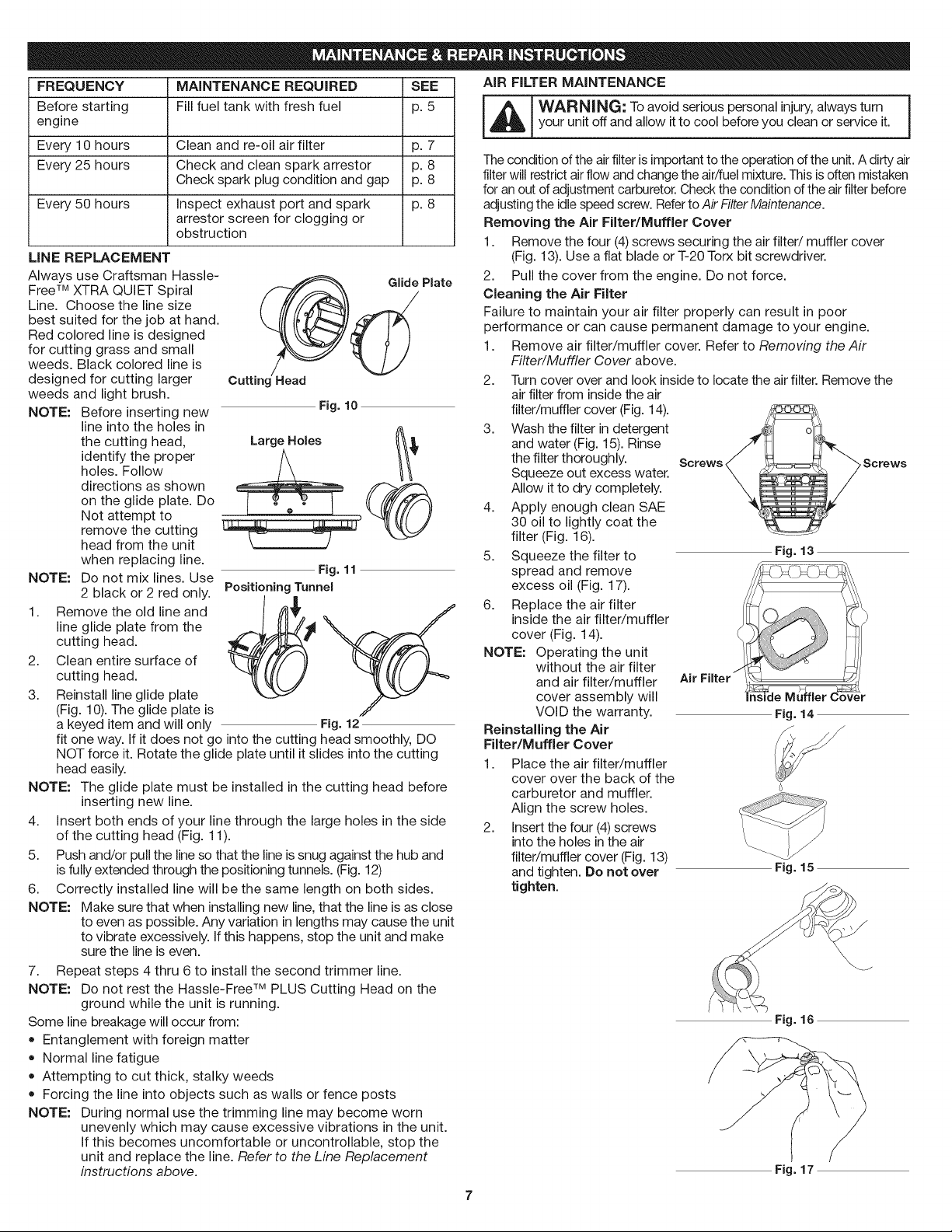
LINE REPLACEMENT
Always use Craftsman Hassle-
Free TM XTRA QUIET Spiral
Line. Choose the line size
best suited for the job at hand.
Red colored line is designed
for cutting grass and small
weeds. Black colored line is
designed for cutting larger
weeds and light brush.
NOTE: Before inserting new
line into the holes in
the cutting head,
identify the proper
holes. Follow
directions as shown
on the glide plate. Do
Not attempt to
remove the cutting
head from the unit
when replacing line.
NOTE: Do not mix lines. Use
2 black or 2 red only.
1. Remove the old line and
line glide plate from the
cutting head.
2. Clean entire surface of
cutting head.
3. Reinstall line glide plate
(Fig. 10). The glide plate is
Glide Plate
Head
Fig. 10
_ _LargeHoles )
Fig. 11
Positioning Tunnel
a keyed item and will only Fig. 12
fit one way. If it does not go into the cutting head smoothly, DO
NOT force it. Rotate the glide plate until it slides into the cutting
head easily.
NOTE: The glide plate must be installed in the cutting head before
inserting new line.
4. Insert both ends of your line through the large holes in the side
of the cutting head (Fig. 11).
5. Push and/or pull the line so that the line is snug against the hub and
is fully extended through the positioning tunnels. (Fig. 12)
6. Correctly installed line will be the same length on both sides.
NOTE: Make sure that when installing new line, that the line is as close
to even as possible. Any variation in lengths may cause the unit
to vibrate excessively. If this happens, stop the unit and make
sure the line is even.
7. Repeat steps 4 thru 6 to install the second trimmer line.
NOTE: Do not rest the Hassle-Free TM PLUS Cutting Head on the
ground while the unit is running.
Some line breakage will occur from:
• Entanglement with foreign matter
Normal line fatigue
Attempting to cut thick, stalky weeds
Forcing the line into objects such as walls or fence posts
NOTE: During normal use the trimming line may become worn
unevenly which may cause excessive vibrations in the unit.
If this becomes uncomfortable or uncontrollable, stop the
unit and replace the line. Referto the Line Replacement
instructions above.
AIR FILTER MAINTENANCE
_L_ WARNING: To avoid serious personal injury, always turn
your unit off and allow it to cool before you clean or service it.
The condition of the air filter is important to the operation of the unit. A dirty air
filter will restrict air flow and change the air/fuel mixture. This is often mistaken
for an out of adjustment carburetor. Check the condition of the air filter before
adjusting the idle speed screw. Referto Air Filter Maintenance.
Removing the Air Filter/Muffler Cover
1. Remove the four (4) screws securing the air filter/muffler cover
(Fig. 13). Use a flat blade or T-20 Torx bit screwdriver.
2. Pull the cover from the engine. Do not force.
Cleaning the Air Filter
Failure to maintain your air filter properly can result in poor
performance or can cause permanent damage to your engine.
1. Remove air filter/muffler cover. Refer to Removing the Air
Filter/Muffler Cover above.
2. Turn cover over and look inside to locate the air filter. Remove the
air filter from inside the air
filter/muffler cover (Fig. 14).
3. Wash the filter in detergent
and water (Fig. 15). Rinse
the filter thoroughly.
Squeeze out excess water.
Allow it to dry completely.
4. Apply enough clean SAE
30 oil to lightly coat the
filter (Fig. 16).
5. Squeeze the filter to
spread and remove
excess oil (Fig. 17).
6. Replace the air filter
inside the air filter/muffler
cover (Fig. 14).
NOTE: Operating the unit
without the air filter
and air filter/muffler
cover assembly will
VOID the warranty.
Reinstalling the Air
Filter/Muffler Cover
Screws
Fig. 13
! ......
Fig. 14
1. Place the air filter/muffler
cover over the back of the
carburetor and muffler.
Align the screw holes.
2. Insert the four (4) screws
into the holes in the air
filter/muffler cover (Fig. 13)
and tighten. Do not over
tighten.
\ J
Fig. 15
,Screws
Fig. 16
Fig. 17
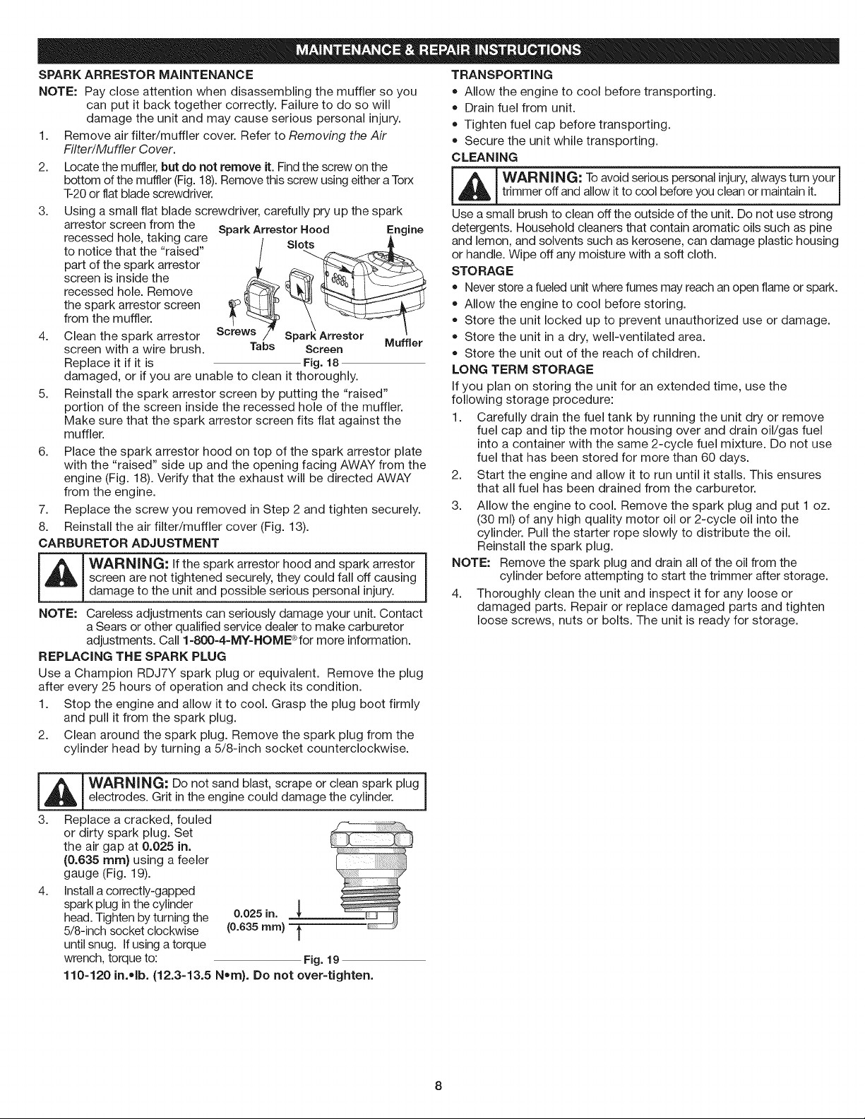
SPARK ARRESTOR MAINTENANCE
NOTE: Pay close attention when disassembling the muffler so you
can put it back together correctly. Failure to do so will
damage the unit and may cause serious personal injury.
1. Remove air filter/muffler cover. Refer to Removing the Air
Filter/Muffler Cover.
2. Locate the muffler, but do not remove it. Find the screw on the
bottom of the muffler (Fig. 18). Remove this screw using either a Torx
T-20 or fiat blade screwdriver.
3. Using a small flat blade screwdriver, carefully pry up the spark
4.
5.
arrestor screen from the
recessed hole, taking care
to notice that the "raised"
part of the spark arrestor
screen is inside the
recessed hole. Remove
the spark arrestor screen
from the muffler.
Clean the spark arrestor
screen with a wire brush.
Replace it if it is
Spark Arrestor Hood Engine
Tabs Screen Muffler
Fig. 18
damaged, or if you are unable to clean it thoroughly.
Reinstall the spark arrestor screen by putting the "raised"
portion of the screen inside the recessed hole of the muffler.
Make sure that the spark arrestor screen fits flat against the
muffler.
6. Place the spark arrestor hood on top of the spark arrestor plate
with the "raised" side up and the opening facing AWAY from the
engine (Fig. 18). Verify that the exhaust will be directed AWAY
from the engine.
7. Replace the screw you removed in Step 2 and tighten securely.
8. Reinstall the air filter/muffler cover (Fig. 13).
CARBURETOR ADJUSTMENT
_ WARNING: If the spark arrestor hood and spark arrestor
screen are not tightened securely, they could fall off causing
1damage to the unit and possible serious personal injury.
NOTE: Careless adjustments can seriously damage your unit. Contact
a Sears or other qualified service dealer to make carburetor
adjustments. Call 1-800-4-MY-HOME_for more information.
REPLACING THE SPARK PLUG
Use a Champion RDJ7Y spark plug or equivalent. Remove the plug
after every 25 hours of operation and check its condition.
1. Stop the engine and allow it to cool. Grasp the plug boot firmly
and pull it from the spark plug.
2. Clean around the spark plug. Remove the spark plug from the
cylinder head by turning a 5/8-inch socket counterclockwise.
TRANSPORTING
• Allow the engine to cool before transporting.
• Drain fuel from unit.
Tighten fuel cap before transporting.
• Secure the unit while transporting.
CLEANING
-- i
_ ARNING: To avoid serious personal injury, always turn your
trimmer off and allow it to cool before you clean or maintain it.
Use a small brush to clean off the outside of the unit. Do not use strong
detergents. Household cleaners that contain aromatic oils such as pine
and lemon, and solvents such as kerosene, can damage plastic housing
or handle. Wipe off any moisture with a soft cloth.
STO RAG E
• Never store a fueled unit where fumes may reach an open flame or spark.
• Allow the engine to cool before storing.
• Store the unit locked up to prevent unauthorized use or damage.
• Store the unit in a dry, well-ventilated area.
• Store the unit out of the reach of children.
LONG TERM STORAGE
If you plan on storing the unit for an extended time, use the
following storage procedure:
1. Carefully drain the fuel tank by running the unit dry or remove
fuel cap and tip the motor housing over and drain oil/gas fuel
into a container with the same 2-cycle fuel mixture. Do not use
fuel that has been stored for more than 60 days.
2. Start the engine and allow it to run until it stalls. This ensures
that all fuel has been drained from the carburetor.
3. Allow the engine to cool. Remove the spark plug and put 1 oz.
(30 ml) of any high quality motor oil or 2-cycle oil into the
cylinder. Pull the starter rope slowly to distribute the oil.
Reinstall the spark plug.
NOTE: Remove the spark plug and drain all of the oil from the
cylinder before attempting to start the trimmer after storage.
4. Thoroughly clean the unit and inspect it for any loose or
damaged parts. Repair or replace damaged parts and tighten
loose screws, nuts or bolts. The unit is ready for storage.
m
_[_ ARNING: Do not sand blast, scrape or clean spark plugelectrodes. Grit in the engine could damage the cylinder.
3. Replace a cracked, fouled
or dirty spark plug. Set
the air gap at 0.025 in.
(0.635 ram) using a feeler
gauge (Fig. 19).
4. Install a correctly-gapped
spark plug in the cylinder |
head. Tighten by turning the 0.025 in.
5/8-inch socket clockwise {0.635 rnrn)
until snug. If using a torque
wrench, torque to: Fig. 19
110-120 in.olb. (12.3-13.5 N=m}. Do not over-tighten.
i

PROBLEM
Primer bulb wasn't pressed enough
Old or improperly mixed fuel
Plugged spark arrestor
The outside temperature is above 90 ° F
SOLUTION
Press primer bulb fully and slowly 10 times
Drain gas tank and add fresh fuel mixture
Clean or replace spark arrestor
Pull the starter rope up to 10-15 times
Old or improperly mixed fuel
Old or improperly mixed fuel
Cutting attachment bound with grass
Plugged spark arrestor
Drain gas tank and add fresh fuel mixture
Drain gas tank and add fresh fuel mixture
Stop the engine and clean the cutting attachment
Clean or replace spark arrestor
Old or improperly mixed fuel
Air filter is plugged
Plugged spark arrestor
Drain gas tank and add fresh fuel mixture
Replace or clean air filter
Clean or replace spark arrestor
9
EngineType............................................................................................................................................................................Air-Cooled,2Cycle
Displacement...........................................................................................................................................................................32cc(1.95cuin.)
IdleSpeedRPM......................................................................................................................................................................2,600- 3,600rpm
OperatingRPM.................................................................................................................................................................................6,800+rpm
IgnitionType.............................................................................................................................................................................ElectronicIgnition
ignitionSwitch..............................................................................................................................................................................RockerSwitch
SparkPlugGap...................................................................................................................................................................0.025in.(0.635mm)
SparkPlug...................................................................................................................................................ChampionRDJ7Yorequivalentplug
Lubrication..................................................................................................................................................................................Fuel/OilMixture
Fuel/OilRatio.................................................................................................................................................................................................40:1
Carburetor......................................................................................................................................................................Diaphragm,All-Position
Starter..........................................................................................................................................................Incredi-PullTM Starting Auto Rewind
Muffler ..................................................................................................................................................................................... Baffled with Guard
Throttle .............................................................................................................................................................................. Manual Spring Return
Fuel Tank Capacity ....................................................................................................................................................................... 13 oz. (384 ml)
Drive Shaft Housing ................................................................................................................................ Steel Tube (Craftsman Convertible TM)
Throttle Control ....................................................................................................................................................................... Finger-Tip Trigger
Approximate Unit Weight (No fuel, with Hassle Free®, shield, and D-handle) ................................................................................ 14 Ibs. (6 kg)
Cutting Mechanism ..................................................................................................................................................... Hassle Free TM Plus Head
Trimming Line ........................................................................................................................................ Hassle Free TM XTRA QUET Spiral Line
* All specifications are based on the latest product information available at the time of printing. We reserve the right to make changes at
any time without notice.
REPAIR PROTECTION AGREEMENTS
Congratulations on making a smart purchase. Your new Craftsman® product is designed and manufactured for years of dependable
operation. But like all products, it may require repair from time to time. That's when having a Repair Protection Agreement can save you
money and aggravation.
Here is what the Repair Protection Plan Agreement includes:
[] Expert service by our 10,000 professional repair specialists
[] Unlimited service and no charge for parts and labor on all covered repairs
[] Product replacement up to $1500 if your cover product can not be fixed
[] Discount of 10% from regular price of service and related installed parts not covered by the agreement; also, 10% off regular price of
preventive maintenance checks
[] Fast help by phone - we call it Rapid Resolution - phone support from a Sears representative. Think of us as a "talking owner's maunal."
Once you purchase the Repair Protection Agreement, a simple phone call is all that it takes for you to schedule service. You can call anytime
day or night, or schedule a service appointment online.
The Repair Protection Agreement is a risk-free purchase. If you cancel for any reason during the product warranty period, we will provide a full refund.
Or a prorated refund anytime after the prodduct warranty period expires. Purchase you Repair Protection Agrrement today!
Some limitations and exclusions apply. For prices and additional information call 1-800-827-6655.
*Coverage in Canada varies on some items. For full datails call Sears Canada at 1-800-361-6665.
Sears Installation Service
For Sears professional installation of home appliances, garage door openers, water heaters, and other major home items, in the U.S.A. or
Canada call 1-800-4-MY-HOME ®.
10
CALiFORNiA/ EPA EMiSSiON CONTROL WARRANTY STATEMENT
Your Warranty Rights and Obligations
The California Air Resources Board, the Environmental Protection Agency, and Sears, Roebuck and Co. (Sears) are pleased to explain the emission
control system warranty on your 2007 and later small off-road engine, in California and the 49 states, new small off-road engines must be designed,
built and equipped to meet the state's stringent anti-smog standards. Sears must warrant the emission control system on your small off-road engine
for the periods of time listed below provided there has been no abuse, neglect or improper maintenance of your small off-road engine.
Your emission control system may include parts such as the carburetor or fuel-injection system, the ignition system, and catalytic converter. Also
included may be hoses, belts, connectors and other emission-related assemblies.
Where a warrantable condition exists, Sears will repair your small off-road engine at no cost to you including diagnosis, parts and labor.
The 2007 and later small off-road engines are warranted for two years, if any emission-related part on your engine is defective, the part will be repaired
or replaced by Sears.
Owners Warranty Responsibilities
As the small off-road engine owner, you are responsible for the performance of the required maintenance listed in your operator's manual. Sears
recommends that you retain all receipts covering maintenance on your small off-road engine, but Sears cannot deny warranty solely for the lack
of receipts or for your failure to ensure the performance of all scheduled maintenance.
• As the small off-road engine owner, you should however be aware that Sears may deny you warranty coverage if your small off-road engine
or a part has failed due to abuse, neglect, improper maintenance or unapproved modifications.
• You are responsible for presenting your small off-road engine to a Sears Authorized Service Center as soon as a problem exists. The
warranty repairs should be completed in a reasonable amount of time, not to exceed 30 days.
if you have any questions regarding your warranty rights and responsibilities, you should call 1-800-4-MY-HOME _>.
Manufacturer's Warranty Coverage
• The warranty period begins on the date the engine or equipment is delivered to the retail purchaser.
• The manufacturer warrants to the initial owner and each subsequent purchaser, that the engine is free from defects in material and
workmanship which cause the failure of a warranted part for a period of two years.
• Repair or replacement of warranted part will be performed at no charge to the owner at an Authorized Sears Service Center. For the nearest
location please contact Sears at: 1=800-4-MY=HOME °.
= Any warranted part which is not scheduled for replacement, as required maintenance or which is scheduled for only for regular inspection
to the effect of "Repair or Replace as Necessary" is warranted for the warranty period. Any warranted part which is scheduled for
replacement as required maintenance will be warranted for the period of time up to the first scheduled replacement point for that part.
• The owner will not be charged for diagnostic labor which leads to the determination that a warranted part is defective, if the diagnostic work
is performed at an Authorized Sears Service Center.
• The manufacturer is liable for damages to other engine components caused by the failure of a warranted part still under warranty.
• Failures caused by abuse, neglect or improper maintenance are not covered under warranty.
• The use of add-on or modified parts can be grounds for disallowing a warranty claim. The manufacturer is not liable to cover failures of
warranted parts caused by the use of add-on or modified parts.
• in order to file a claim, go to your nearest Authorized Sears Service Center. Warranty services or repairs will be provided at all Authorized
Sears Service Centers.
• Any manufacturer approved replacement part may be used in the performance of any warranty maintenance or repair of emission related
parts and will be provided without charge to the owner. Any replacement part that is equivalent in performance or durability may be used
in non-warranty maintenance or repair and will not reduce the warranty obligations of the manufacturer.
Emission Warranty Parts List:
The following components are included in the emission-related warranty of the engine: air filter, carburetor, primer, fuel lines, fuel pick up/fuel
filter, ignition module, spark plug, and muffler. Valves and Cam are additionally included if your engine is a 4-Stroke Model.
CALiFORNiA EVAPORATIVE EMiSSiON CONTROL WARRANTY STATEMENT
Your Warranty Rights and Obligations
The California Air Resources Board and Sears, Roebuck and Co. (Sears) is pleased to explain the evaporative emission control system's warranty
on your 2007 model year and later small off-road (equipment type) engine, in California, new equipment that use small off-engines must be designed,
built, and equipped to meet the State's stringent anti-smog standards Sears must warrant the evaporative emission control system on your small
off-road Lawn & Garden engine for the period listed below provided there has been no abuse, neglect or improper maintenance of your equipment.
Your evaporative emission control system may include parts such as: carburetors, fuel tanks, fuel lines, fuel caps, valves, canisters, filters, vapor
hoses, clamps, connectors, and other associated components. For engines less than or equal to 80 cc, only the fuel tank is subject to the
evaporative emission control warranty requirements of this section. The displacement of your small off road engine is less than 80 cc.
Manufacturer's Warranty Coverage
This evaporative emission control system is warranted for two years. If any evaporative emission-related part on your equipment is defective,
the part will be repaired or replaced by Sears.
Owner's Warranty Responsibilities
• As the small off-road Lawn & Garden engine owner, you are responsible for performance of the required maintenance listed in your owner's
manual. Sears recommends that you retain all receipts covering maintenance on your Lawn & Garden Engine but Sears cannot deny
warranty solely for the lack of receipts.
As the small off-road Lawn & Garden engine owner, you should however be aware that the Sears may deny you warranty coverage if your
fuel tank has failed due to abuse, neglect, or improper maintenance or unapproved modifications.
You are responsible for presenting your Lawn & Garden fuel tank to Sears distribution center or service center as soon as the problem exists.
The warranty repairs should be completed in a reasonable amount of time, not to exceed 30 days. If you have a question regarding your
warranty coverage, you should contact Sears at 1-800-4-MY-HOME _.
11
Defects Warranty Requirements
(a) The warranty period begins on the date the engine or equipment is delivered to an ultimate purchaser.
(b) General Evaporative Emissions Warranty Coverage. The fuel tank must be warranted to the ultimate purchaser and any subsequent owner
that the evaporative emission control system when installed was:
(1) Designed, built, and equipped so as to conform with all applicable regulations; and
(2) Free from defects in materials and workmanship that causes the failure of a warranted part for a period of two years.
(c) The warranty on evaporative emissions-related parts will be interpreted as follows:
(1) Any warranted part that is not scheduled for replacement as required maintenance in the written instructions must be warranted for the
warranty period defined in subsection (b)(2). If any such part fails during the period of warranty coverage, it must be repaired or replaced
by Sears. Any such part repaired or replaced under the warranty must be warranted for a time not less than the remaining warranty
period.
(2) Any warranted part that is scheduled only for regular inspection in the written instructions must be warranted for the warranty period defined in
subsection (b)(2).A statement in such written instructions to the effect of "repair or replace as necessary" will not reduce the period of warranty
coverage. Any such part repaired or replaced under warranty must be warranted for a time not less than the remaining warranty period.
(3) Any warranted part that is scheduled for replacement as required maintenance in the written instructions must be warranted for the
period of time prior to the first scheduled replacement point for that part. If the part fails prior to the first scheduled replacement, the
part must be repaired or replaced by the Sears. Any such part repaired or replaced under warranty must be warranted for a time not less
than the remainder of the period prior to the first scheduled replacement point for the part.
(4) Repair or replacement of any warranted part under the warranty provisions of this article must be performed at no charge to the owner
at a warranty station.
(5) Not withstanding the provisions of subsection (4) above, warranty services or repairs must be provided at distribution centers that are
franchised to service the subject engines or equipment.
(6) The owner must not be charged for diagnostic labor that leads to the determination that a warranted part is in fact defective, provided
that such diagnostic work is performed at a warranty station.
(7) Throughout the evaporative emission control system's warranty period set out in subsection (b)(2), Sears must maintain a supply of
warranted parts sufficient to meet the expected demand for such parts.
(8) Manufacturer approved replacement parts must be used in the performance of any warranty maintenance or repairs and must be provided
without charge to the owner. Such use will not reduce the warranty obligations of the manufacturer issuing the warranty.
(9) The use of any add-on or modified parts will be grounds for disallowing a warranty claim made in accordance with this article. The
manufacturer issuing the warranty will not be liable under this Article to warrant failures of warranted parts caused by the use of an add-
on or modified part.
(1O) Sears shall provide any documents that describe the warranty procedures or policies within five working days of request by the Air Resources Board.
Emission Warranty Parts List
(1) Fuel Tank
Written instructionsfor the maintenance and use of the evaporative emissions control system by the owner shall be furnished with each new engine or equipment.
12
Manual del Operador
MRN
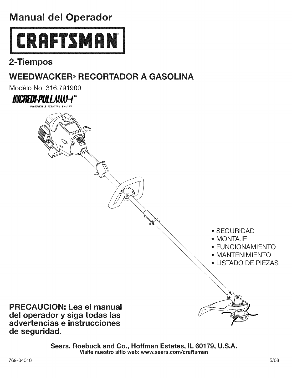
2-Tiempos
WEEDWACKER_ RECORTADOR A GASOLINA
Modelo No. 316.791900
U_EUEVASLt S TAR TtNG E A S E TM
,, SEGURIDAD
* MONTAJE
* FUNCIONAMIENTO
* MANTENIMIENTO
* LISTADO DE PIEZAS
PRECAUCION: Lea el manual
del operador y siga todas las
advertencias e instrucciones
de seguridad.
Sears, Roebuck and Co., Hoffman Estates, IL 60179, U.S.A.
Visite nuestro sitio web: www.sears.com/craftsman
769-04010 5/08
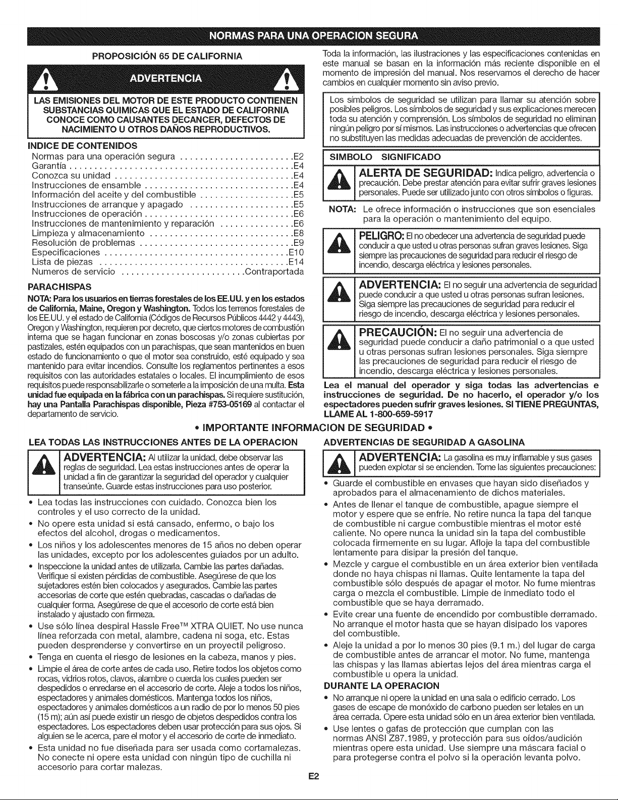
PROPOSlCION 65 DE CALIFORNIA Toda la informaci6n, las ilustraciones y las especificaciones contenidas en
LAS EMISIONES DEL MOTOR DE ESTE PRODUCTO CONTIENEN
SUBSTANCIAS QUIMICAS QUE EL ESTADO DE CALiFORNiA
CONOCE COMO CAUSANTES DECANCER, DEFECTOS DE
NACIMIENTO U OTROS DA_IOS REPRODUCTIVOS.
INDICE DE CONTENIDOS
Normas para una operaci6n segura ....................... E2
Garantia ............................................. E4
Conozca su unidad .................................... E4
Instrucciones de ensamble .............................. E4
Informaci6n del aceite y del combustible ................... E5
Instrucciones de arranque y apagado ..................... E5
Instrucciones de operaci6n .............................. E6
Instrucciones de mantenimiento y reparaci6n ............... E6
Limpieza y almacenamiento ............................. E8
Resoluci6n de problemas ............................... E9
Especificaciones ..................................... E10
Lista de piezas ...................................... E14
Numeros de servicio ......................... Contraportada
PARAC H ISPAS
NOTA:Para los usuariosen tierras forestales de los EE.UU.y en losestados
de California, Maine, Oregon y Washington. Todos los terrenosforestales de
los EE.UU.y el estadode California(C6digos de RecursosPublicos4442y 4443),
Oregony Washington,requierenpot decreto,que ciertos motores de combusti6n
internaque se hagan funcionar en zonas boscosas y/o zonas cubiertas por
pastizales,esten equipados con un parachispas,que sean mantenidos en buen
estado de funcionamiento o que el motor sea construido, este equJpadoy sea
mantenido para evitar Jncendios.Consulte los reglamentos pertinentes a esos
requisitos con las autorJdadesestatales o locales. El incumplimiento de esos
requisitospuede responsabilizarleo someterlea laimposici6n de unamulta. Esta
unidadrue equipada en lafAbdca con un parachispas.Si requieresustituci6n,
hay una Pantalla Parachispas disponible, Pieza #753=05169al contactar el
departamento de servicio.
este manual se basan en la informaci6n mas reciente disponJble en el
momento de impresi6n del manual. Nos reservamos el derecho de hacer
cambios en cualquier momento sin aviso previo.
Los simbolos de seguridad se utilizan para Ilamar su atenci6n sobre
posibles peligros. Los sfmbolos de seguridad y sus explJcacionesmerecen
toda su atenci6n y comprensi6n. Los dmbolos de seguridad no elJminan
nJngQnpeligro por si mJsmos.Las instrucciones o advertencias que ofrecen
no substituyen las medidas adecuadas de prevenci6n de accidentes.
SIMBOLO SIGNIFICADO
,_ ALERTA DE SEGURIDAD: Indicapeligro, advertencia o
precauci6n. Debe prestaratenci6n para evitarsufrir graves lesiones
personales. Puedeser utilizadojunto con otros simbolos o figuras.
NOTA:
Le ofrece informaci6n o instrucciones que son esenciales
para la operaci6n o mantenimiento del equipo.
PELIGRO: Elno obedecer una advertenciade seguridadpuede
conducir a que usted u otras personassufrangraves lesiones.Siga
siemprelas precaucionesde seguridadpara reducirel riesgode
incendio,descargaelectricay lesionespersonales.
ADVERTENCIA: El no seguJr una advertencia de seguridad
puede conducir a que usted u otras personas sufran lesiones.
Siga siempre las precauciones de seguridad para reducir el
rieego de incendio,descarga electrica y lesiones personales.
PRECAUCION: El no seguir una advertencia de
seguridad puede conducir a dar_o patrimonial o a que usted
u otras personas sufran lesiones personales. Siga siempre
las precauciones de seguridad para reducir el riesgo de
incendio, descarga electrica y lesiones personales.
Lea el manual del operador y sJga todas las advertencias e
instrucciones de seguridad. De no hacerlo, el operador y/o los
espectadores pueden sufrir graves lesiones. Sl TIENE PREGUNTAS,
LLAME AL 1-800=659-5917
• IMPORTANTE INFORMACION DE SEGURIDAD •
LEA TODAS LAS INSTRUCCIONES ANTES DE LA OPERACION
_ DVERTENClA: AI utilizarla unJdad,debe observar las
reglas de seguridad. Lea estas instruccionesantes de operar la
unJdada fin de garantJzarla seguridad del operador y cualquier
transeunte. Guarde estas instrucciones para uso posterior.
• Lea todas las instrucciones con cuidado. Conozca bien los
controles y el uso correcto de la unidad.
No opere esta unidad siestA cansado, enfermo, o bajo los
efectos del alcohol, drogas o medicamentos.
Los nitros y los adolescentes menores de 15 argos no deben operar
las unidades, excepto por los adolescentes guiados por un adulto.
Inspeccione la unidad antes de utJlizarla.Cambie laspartes da_adas.
Verifiquesi existen perdidas de combustible. Asegurese de que los
sujetadores esten bien colocados y asegurados. Cambie las partes
accesorias de corte que esten quebradas, cascadas o da_adas de
cualquier forma. Asegurese de que el accesorJode corte esta bien
instalado y ajustado con firmeza.
Use s61o linea despiral Hassle Free TM XTRA QUIET. No use nunca
linea reforzada con metal, alambre, cadena ni soga, etc. Estas
pueden desprenderse y convertirse en un proyectil peligroso.
Tenga en cuenta el riesgo de lesiones en la cabeza, manos y pies.
Limpie el Areade corte antes de cada uso. Retiretodos los objetos como
rocas, vidrios rotos, clavos, alambre o cuerda los cuales pueden ser
despedidos o enredarse en el accesorio de corte. Aleje a todos los niSos,
espectadores y animales domesticos. Mantenga todos los niSos,
espectadores y animales domesticos a un radio de por Io menos 50 pies
(15 m); aun asi puede existir un riesgo de objetos despedidos contra los
espectadores. Los espectadores deben usar protecci6n para sus ojos. Si
alguien se le acerca, pare el motor y el accesorio de corte de inmediato.
Esta unidad no fue diser_ada para ser usada como cortamalezas.
No conecte ni opere esta unidad con ningQn tipo de cuchilla ni
accesorio para cortar malezas.
ADVERTENCIAS DE SEGURIDAD A GASOLINA
_ ADVERTENCJA: La gasolinaes muy inf'amabley sus gases ipueden explotar si se encienden.Tome lassiguientesprecauciones:
Guarde el combustible en envases que hayan sido diser_ados y
aprobados para el almacenamiento de dichos materiales.
Antes de Ilenar el tanque de combustible, apague siempre el
motor y espere que se enfrie. No retire nunca la tapa del tanque
de combustible ni cargue combustible mientras el motor este
caliente. No opere nunca la unidad sin la tapa del combustible
colocada firmemente en su lugar. Afloje la tapa del combustible
lentamente para disipar la presi6n del tanque.
Mezcle y cargue el combustible en un Area exterior bien ventilada
donde no haya chispas ni llamas. Quite lentamente la tapa del
combustible s61o despues de apagar el motor. No fume mientras
carga o mezcla el combustible. Limpie de inmediato todo el
combustible que se haya derramado.
Evite crear una fuente de encendido pot combustible derramado.
No arranque el motor hasta que se hayan disipado los vapores
del combustible.
Aleje la unidad a pot Io menos 30 pies (9.1 m.) del lugar de carga
de combustible antes de arrancar el motor. No fume, mantenga
las chispas y las llamas abiertas lejos del Area mientras carga el
combustible u opera la unidad.
DURANTE LA OPERACION
= No arranque ni opere la unidad en una sala o edificio cerrado. Los
gases de escape de mon6xido de carbono pueden ser letales en un
b_reacerrada. Opere esta unidad s61oen un b_reaexterior bien ventilada.
Use lentes o gafas de protecci6n que cumplan con las
normas ANSI Z87.1989, y protecci6n para sus oidos/audici6n
mientras opere esta unidad. Use siempre una mascara facial o
para protegerse contra el polvo si la operaci6n levanta polvo.
E2
• Use pantalones largos y gruesos, botas, guantes y camisa de manga
larga. No use ropa holgada, alhajas, pantalones cortos, sandalias ni
este descalzo. Sostenga el cabello sobre el nivel de los hombros.
La protecci6n accesoria de corte debe estar siempre colocada en
su lugar mientras opere la unidad. No opere la unidad con las dos
lineas de corte extendidas, y la linea correcta instalada. No
extienda la linea de corte mas alia de la Iongitud de la protecci6n.
Esta unidad cuenta con un embrague. El accesorio de corte
permanece estacionario cuando el motor esta en marcha lenta. Si no
Io hace, haga ajustar la unidad por un t6cnico de servicio autorizado.
Ajuste {a manija en D a su tamafio de modo que {ebrinde el mejor agarre.
AsegQrese de que el accesorio de corte no esta en contacto con
ningQn objeto antes de arrancar la unidad.
Use la unidad Qnicamente con la luz del dia o con buena luz artificial.
Evite arrancar la unidad accidentalmente. Col6quese en posici6n
de inicio siempre que tire de la cuerda de arranque. El operador y
la unidad deben estar en una posici6n estable al comenzar. Lea
las instrucciones de Arranque y Apagado.
Use la herramienta adecuada. No use esta unidad para ninguna
tarea para la cual no ha sido disefiada.
Sostenga siempre la unidad con ambas manos mientras este en
funcionamiento. Sostenga con firmeza tanto el mango como la
manija auxiliar.
Mantenga las manos, la cara y los pies {ejosde todas las partes
m6viles. No {ntente tocar ni detener el accesorio de corte mientras gira.
No toque el motor, el bastidor del engranaje ni el silenciador.
Estas partes se calientan mucho con la operaci6n. Luego de
apagar la unidad, permanecen calientes durante un tiempo breve.
No opere el motor a una velocidad mayor que la necesaria para
cortar, recortar o recortar los bordes. No haga funcionar el motor
a alta velocidad mientras no esta cortando.
Apague siempre el motor cuando demore el corte o mientras
camina entre zonas de corte.
Si golpea o se enreda con algQn objeto extrafio, apague el motor de
inmediato y verifique si hay dafios. Repare todos los dafios antes de
volver a intentar operar la unidad. No opere la unidad si tiene piezas
flojas o dafiadas.
Apague el motor para realizar todo el mantenimiento,
reparaciones o cambio del accesorio de corte u otros accesorios.
Use s61opiezas y accesorios de repuesto del fabricante del equipo
original para esta unidad. Puede obtenerlos en su proveedor de servicio
autorizado. El uso de piezas y accesorios que no son equipo origina;
puede causar graves lesiones a{operador o el dafio de su unidad, y la
cancelaci6n de su garantfa.
Mantenga la unidad libre de vegetaci6n y otros materiales.
Pueden alojarse entre el accesorio de corte y la protecci6n.
Parareducir el riesgo de {ncend{o,cambie los silenciadoresy
amortiguadores de chispas defectuosos, mantenga el motor y e{silenciador
libre de pasto, hojas, grasaexcesivao acumulacionesde carbono.
OTRAS ADVERTENCIAS DE SEGURIDAD
= No guarde nunca la unidad con combustible en el tanque en un edificio
donde los gases puedan Ilegar a una llama abierta o a una chispa.
Espere que el motor se enfrie antes de guardar o transportar la
unidad. AsegQrese de que la unidad este segura al transportarla.
Guarde la unidad bajo Ilave en un lugar adecuado y seco para
evitar que sea usada por personas no autorizadas y se dafie,
fuera del alcance de los nifios.
Nunca moje ni rode {aunidad con agua ni con ningun otro Ifquido.
Mantenga {as manijas secas, limpias y sin residuos. Limpie la unidad
{uego de cada uso, lea {as instrucciones de Limpieza y Almacenamiento.
Guarde estas instrucciones. ConsQItelas con frecuencia y
utilicelas para ensefiar a otros usuarios. Si le presta esta unidad a
alguien, prestele tambien estas instrucciones.
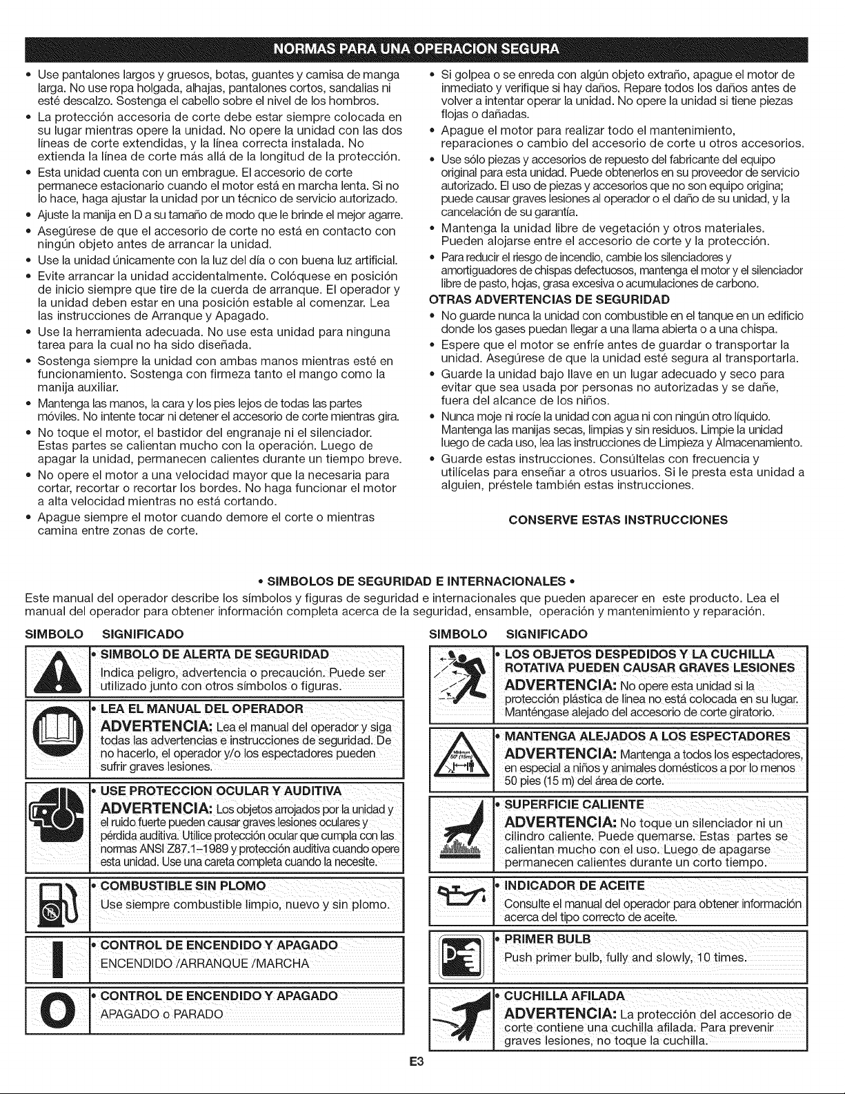
CONSERVE ESTAS {NSTRUCCIONES
,' SiMBOLOS DE SEGURIDAD E {NTERNACIONALES •
Este manual del operador describe los simbolos y figuras de seguridad e internacionales que pueden aparecer en este producto. Lea el
manual del operador para obtener informaci6n completa acerca de la seguridad, ensamble, operaci6n y mantenimiento y reparaci6n.
SIMBOLO SIGNIFICADO
SiMBOLO DE ALERTA DE SEGURiDAD
!ndica pelig[o, advertenCia o precauci6nl Puede
utilizado junto con otros simbolos o figuras.
, LEA EL MANUAL DEL OPERABOR
ADVERTENCIA: Ceael manual dei 0peiador y siga
todas !as advertencias e instruccionesde seguridadl De
no hacerlo, el operador y/o los espectadores pueden
sufrir graves lesiones.
r4}L¸
, USE PROTECCION OCULAR Y AUDITIVA
ADVERTENCIA: Los0bjet0S arrojadosporla unidad
el ruido fuerte pueden causargraves lesiones0cularesy
p6rdida auditiva. Utilice protecci6n ocular que cumpla con las
normas ANSIZ87,1--1989 y protecci6n auditivacuando opere
esta unidad. Use una caretacompleta cuando la necesite.
r-i •COMBUST'BLES'NPLOMO
,_L_ [ Usesiemprecombustbe mpo nuevoysnpomo,
I
| CONTROLDEENCENDIDO¥ APAGADO
[ ENCEND DO/ARRANQUE !MARCHA
{.CONTROLDEENCEND,DO¥APAGADO
[ APAGAOOoPARAOO
E3
SIMBOLO SIGNIFICADO
= LOS OBJETOS DESPEDIDOS Y LA CUCHILLA
ROTATIVA PUEDEN CAUSAR GRAVES LESIONES
ADVERTENClA: No opere esta unidad si la
protecci6n plAstica de linea no estA colocada en su lugar.
Mantengase alejado del accesorio de corte giratorio.
• MANTENGA ALEJADOS A LOS ESPECTADORES
ADVERTENCIA: Mantenga a todos los espectadores,
en especial a nifios y animales dom6sticos a por Io menos
50 pies (15 m) del Area de corte.
• SUPERFICIE CALIENTE I
i
ADVERTENCIA: No toque un silenciador ni un
cilindro caliente. Puede quemarse, Estas partes se
calientan mucho con el uso. Luego de apagarse
permanecen calientes durante un corto tiern po.
o INDICADOR DE ACEITE
t { Consulte el manual del operador para obtener informaci6n {
.[ acerca del tipo correcto de aceite. I
" PRIMER BULB
j Push pr mer bu b, fu y and slowly, 10 times.
_=_ " CUCHILLA AFILADA
_,_'1_ ADVERTENCIA: La protecci6n del accesor{o de
corte contiene una cuchilla afilada. Para prevenir
.[ graves es ones. no toque a cuch a.
GARANTIA TOTAL DE CRAFTSMAN
Si este producto de Craftsman Professional falla debido a un defecto en el material o en la mano de obra dentro de un periodo de tres a_os
a partir de la fecha de compra, devuelvalo a cualquier tienda o Centro de Servicio de Piezas y Reparaciones Sears u otto establecimiento de
Craftsman en los Estados Unidos para que sea reparado sin costo alguno (o ser reemplazado si resulta imposible repararlo).
Esta garantia se aplica solamente durante 90 dias si este producto en algQn momento se utiliza para fines comerciales o de alquiler.
Esta garant{a abarca SOLAMENTE los defectos en el material o en la mano de obra. Sears NO pagar_:
• Los articulos consumibles que se desgasten debido al uso normal dentro del periodo de garantia.
• Las reparaciones necesarias debidas a accidente asi como por no operar o no mantener el equipo de acuerdo con todas las instruccionesprovistas.
• Mantenimiento preventivo, o las reparaciones necesarias debido a mezcla incorrecta de combustible, combustible contaminado o viejo.
Esta garantia le concede a usted derechos legales especificos, y usted pudiera tener otros derechos que varian de un estado a otro.
Sears, Roebuck and Co., Hoffman Estates, IL 60179
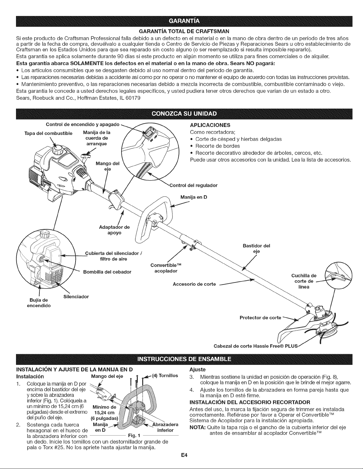
Control de encendido y apagado
Tapa del combustible Manija de la
cuerda de
arranque
Mango del
eje
APLICACIONES
Como recortadora;
Corte de cesped y hierbas delgadas
Recorte de bordes
Recorte decorativo alrededor de arboles, cercos, etc.
Puede usar otros accesorios con la unidad. Lea la lista de accesorios.
-Control del regulador
Manija en D
Bujia de
encendido
Adaptadorde
apoyo
Cubierta del silenciador /
filtro de aire
Bombilla del cebador
Silenciador
Convertible TM
acoplador
Accesorio de co_e
Bastidor del
eje
Protector de corte
Cuchilla de
corte de
Ifnea
Cabezal de corte Hassle Free@
INSTALACION Y AJUSTE DE LA MANIJA EN D
Instalaci6n Mango del eje
1.
2.
Coloque la manija en D por _'
encima del bastidor del eje
y sobre la abrazadera
inferior (Fig. 1). Col6quela a
un minimo de 15,24 cm (6 Mfnirnode
pulgadas) desde el extremo
del puno del eje.
Sostenga cada tuerca
hexagonal en el hueco de en D inferior
la abrazadera inferior con Fig. 1
un dedo. Inicie los tornillos con un destornillador grande de
pala o Torx #25. No los apriete hasta ajustar la manija.
E4
Ajuste
3. Mientras sostiene la unidad en posici6n de operaci6n (Fig. 8),
coloque la manija en Den la posici6n que le brinde el mejor agarre.
4. Ajuste los tornillos de la abrazadera en forma pareja hasta que
la manija en D este firme.
INSTALACION DEL ACCESORIO RECORTADOR
Antes del uso, la marca la fijaci6n segura de trimmer es instalada
correctamente. Refierase por favor a Operar el Convertible TM
Sistema de Acoplador para la instalaci6n apropiada.
NOTA: Quite la tapa roja o el gancho de la cubierta inferior del eje
antes de ensamblar al acoplador Convertible TM
INSTRUCCIONES PARA MEZCLAR EL ACEITE Y EL COMBUSTIBLE
El combustible viejo o mal mezclado son los motivos principales del
mal funcionamiento de la unidad. AsegQrese de usar combustible
nuevo, limpio y sin plomo. Siga las instrucciones en detalle para
mezclar correctamente el aceite y el combustible.
Definici6n de los combustibles de rnezcla
Los combustibles actuales con frecuenciason una mezcla de gasolina y
oxigenantes como pot ejemplo etanol, metanol o MTBE (eter).Elcombustible
mezclado con alcohol absorbe agua. Una cantidad tan pequefia como el 1%
de agua enel combustible puede causar la separaci6ndel combustible y el
aceite. Forma Acidos cuando estA almacenado. Cuando usecombustible
mezclado con alcohol, use combustible nuevo (de menosde 60 d{as).
Uso de combustibles de mezcla
Si usted opta pot usar un combustible de mezcla o si su uso es
inevitable, tome las precauciones recomendadas.
• Use siempre una mezcla fresca de combustible segOn Io indica
su manual del operador.
Agite siempre la mezcla de combustible antes de cargaflo en la unidad.
Drene el tanque y haga funcionar el motor en seco antes de
guardar la unidad.
Uso de aditivos en el combustible
La botella de aceite de 2 ciclos que vino con su unidad contiene un aditivo
en el combustible que ayudara a inhibirla corrosi6n y a reducir la formaci6n
de dep6sitos de goma. Se recomienda que use s61oel aceite de 2 ciclos
con esta unidad. Si es inevitable, use un buen aceite de 2 ciclos elaborado
para motores enffiados por aire junto con un aditivo parael combustible
como por ejemplo el estabilizador de gasolina STA-BIL® o similar.Agregue
23 mL (0,8 onzas) de aditivo de combustible por gal6n de combustible de
acuerdo con las instruccionesdel envase. NUNCA agregue aditivos
directamente en el tanque de combustible de la unidad.
A I PRECAUCION: Para que el motor funcione correctamente
I _ I Y con la mayor fiabilidad, preste mucha atenci6n a las
-- I instruccionesde mezcla de aceite y combustible del envase de
I I aceite de 2 ciclos. El uso de combustible mezclado en forma
h==._ incorrecta puede dafiar sefiamente el motor.
Mezcle bien la proporci6n correcta de aceite para motor de 2 ciclos y
gasolina sin plomo en una lata de combustible pot separado. Use una
proporci6n de 40:1 de combustible y aceite. No los mezcle directamente
en el tanque de combustible de la unidad. Consulte las proporciones
especificas de mezcla de gasolina y aceite en la tabla siguiente.
NOTA:
NOTA:
3,8 litros (un gal6n) de
gasolina sin plomo
mezclada con una
botella de 95 mL (3,2
onzas) de aceite de 2
ciclos es una
proporci6n de 40:1 de
combustible y aceite.
Elimine la mezcla vieja
de aceite y
combustible de
acuerdo con los
reglamentos federales
estatales y locales.
GASOLINA SIN
PLOMO
3,8 MTROS
(1 GALON de
EE.UU.)
1 LITRO
PROPORCION DE LA MEZCLA = 40:1
ACEITE DE 2
CICLOS
95 rnL
(3,20NZAS
FLUIDAS}
25 mL
ADVERTENCIA: La gasolina es muy inflamable. Los
gases pueden explotar si se encienden. Apague siempre el
motor y espere que se enfrie antes de cargar el tanque de
combustible. No fume mientras Ilena el tanque. Mantenga
las chispas y las llamas lejos del Area.
ADVERTENOIA: Saque la tapa del combustible lentamente
para evitar lesionarse con el rociado del combustible. No opere
nunca la unidad sin latapa del combustible firmemente colocada
en su lugar.
ADVERTENCIA: Cargue el combustible en un Area exterior
limpia y bien ventilada. Limpie de inmediatotodo combustible
que se haya derramado. Evite crear una fuente de encendido con
el combustible derramado. No arranque el motor hasta que se
hayan evaporado los gases del combustible.
E5
ADVERTENClA: Use esta unidad s61o en un Area
exterior bien ventilada. Los gases de escape de mon6xido
de carbono pueden ser letales en un Area cerrada.
ADVERTENOIA: Evitelos arranquesaccidentales. Cobquese
en posicbn de iniciocuando tirede la cuerda de arranque (Fig.5). El
operador y la unidad deben estar en una posicbn establealarrancar
launidad paraevitar graves lesionespersonales.
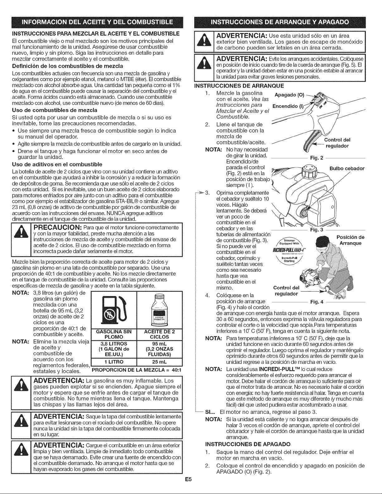
INSTRUCCIONES DE ARRANQUE
1. Mezcle la gasolina
con el aceite. Vea las
Instrucciones para
Mezclar el Aceite y el
Combustible.
2. Llene el tanque de
combustible con la
mezcla de
combustible/aceite.
NOTA: No hay necesidad
de girar la unidad.
Encendido/de
Apagado (O) _-_.._
---- regulador
Fig. 2
_3.
4.
parada el control __ Bulbo cebador
(Fig. 2) esta en la _ __ /
posici6n de trabajo i _(>./'>__ J
siempre ( I ). _ f_'__/.y
Opfimacompletamente _- {/ / f _f_
el cebador y sueltelo 10 _ ./ _j//._"-_ \_
veces. Hagalo \ _,,"_:/ )/ oli
lentamente. Sedebera \"%.._ (_f_-_._l tl
ver un poco de ,,_'_ -_,4,__ /l ..S.)
combustible en el \ __.-j_
cebador yen las Fig. 3
Sl... El
NOTA:
tubefias de alimentaci6n
de combustible (Fig. 3).
Si no puede ver el
combustible en el
cebador, opfimalo y
sueltelo tantas veces
como sea necesafio
hasta que vea
combustible en el
mismo. Control del
ColSquese en la regulador
posiciSn de arranque Fig. 4
(Fig. 4) y hale el cordSn
de arranque con energia hasta que el motor arranque. Espera
30 a 60 segundos, entonces exprima la valvula reguladora para
controlar el corte o la velocidad que sopla.Para temperaturas
infefiores a 10°C (50° F), tenga en cuenta la siguiente nota.
NOTA: Para temperaturas infefiores a 10°C (50° F), deje que la
unidad funcione en vacio durante 60 segundos antes de
opfimir el regulador. Luego optima el regulador y mantengalo
oprimido durante otros 60 segundos antes de permitir que la
unidad regrese a la posici6n de marcha en vacio.
NOTA: La unidad usa INCREDI-PULL TM Io cual reduce
considerablemente el esfuerzo requerido para arrancar el
motor. Debe halarel cord6n de arranque Io suficiente para oir
que el motor trata de arrancar.No es necesario halar el cord6n
con energia: no hay fuerte resistencia al halar.Tenga en cuenta
que este metodo de arranque es muy diferente (y mucho mas
facil) del que usted pudiera estar acostumbrado a usar.
motor no arranca, regrese al paso 3.
Si la unidad estA caliente y no Iogra arrancar despues de
halar 3 veces el cord6n de arranque, apfiete el control del
obturador y hale el cord6n de arranque hasta que la unidad
arranque.
INSTRUCCIONES DE APAGADO
1. Saque la mano del control del regulador. Deje enfriar el
motor en marcha en vacio.
2. Coloque el control de encendido y apagado en posici6n de
APAGADO (O)(Fig. 2).
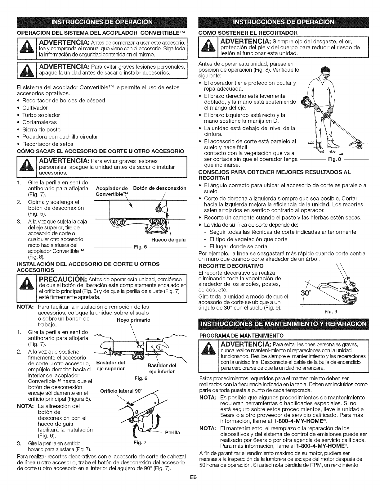
OPERACIONDELSISTEMA DEL ACOPLADOR CONVERTIBLE TM
lea y comprenda el manual que viene con el accesorio. Siga toda
a nformac 6n de seguridad conten da ene m smo.
-- i_L_ DVERTENCIA: Para evitar graves lesiones personales,apague la unidad antes de sacar o instalar accesorios.
El sistema del acoplador Convertible TM le permite el uso de estos
accesorios optativos.
• Recortador de bordes de cesped
Cultivador
Turbo soplador
Cortamalezas
Sierra de poste
Podadora con cuchilla circular
Recortador de setos
COMO SAOAR EL AOOESORIO DE CORTE U OTRO AOOESORIO
I _ _ADVERTENCIA: Para evitar graves lesiones j
personales, apague la unidad antes de sacar o instalar
accesorios.
1. Gire la perilla en sentido
antihorario para aflojarla
(Fig. 7).
2. ©pimaysostenga el
bot6n de desconexi6n
(Fig. 5).
3. A la vez que sujeta la caja
del eje superior, tire del
accesorio de corte o
cualquier otro accesorio
recto hacia afuera del
acoplador Convertible TM
(Fig. 6).
Acoplador de Bot6n de desconexi6n
Conv_
Hueco de guia
Fig. 5
INSTALACION DEL ACCESORIO DE CORTE U OTROS
ACCESORIOS
_1._ RECAUCI6N: Antes de operar esta unidad, cerci6rese
de que el bot6n de liberaci6n este completamente encajado en
el orificio principal (Fig. 6) y de que la perilla de ajuste (Fig. 7)
este firmemente apretada.
NOTA: Para facilitar la instalaci6n o remoci6n de los
accesorios, coloque la unidad sobre el suelo
o sobre un banco de Hoyo primario
trabajo
1. Gire la perilla en sentido
antihorario para aflojarla
Bastidor del
Bastidor del
eje superior eje inferior
Fig. 6
(Fig. 7).
A la vez que sostiene
firmemente el accesorio
de corte u otro accesorio,
empQjelo derecho hacia el
interior del acoplador
Convertible TM hasta que el
bot6n de desconexi6n
encaje s61idamente en el
orificio principal (Figura 6).
NOTA: La alineaci6n del
bot6n de
desconexi6n con el
hueco de guia
facilitara la instalaci6n
(Fig. 6).
3. Gire la perillaen sentido
horario para ajustarla(Fig.7).
Orificio_ .... PeriUa
Fig. 7
Para realizar recortes decorativos con el accesorio de corte de cabezal
de linea u otro accesorio, trabe el bot6n de desconexi6n del accesorio
de corte u otro accesorio en el interior del agujero de 90° (Fig. 7).
COMO SOSTENER EL RECORTADOR
_L_[ DVERTENCIA: Siempre ojo eel desgaste, el oir, 1
protecci6n del pie y del cuerpo para reducir el riesgo de
es 6n a func onar esta un dad.
Antes de operar esta unidad, p_,rese en
posici6n de operaci6n (Fig. 8). Verifique Io
siguiente:
El operador tiene protecci6n ocular y
ropa adecuada.
El brazo derecho esta levemente
doblado, y la mano esta. sosteniendo
el mango del eje.
El brazo izquierdo est,, recto y la
mano sostiene la manija en D.
La unidad esta debajo del nivel de la
cintura.
El accesorio de corte esta paralelo al
suelo y hace facil
contacto con la vegetaci6n que va a _ ,_
ser cortada sin que el operador tenga Fig. 8
que inclinarse.
CONSEJOS PARA OBTENER MEJORES RESULTADOS AL
RECORTAR
El b.ngulo correcto para ubicar el accesorio de corte es paralelo al
suelo.
Corte de derecha a izquierda siempre que sea posible. Cortar
hacia la izquierda mejora la eficiencia de la unidad. Los recortes
salen arrojados en sentido contrario al operador.
Recorte Qnicamente cuando el pasto y las hierbas esten secas.
La vida de su linea de corte depende de:
Seguir todas las tecnicas de corte indicadas anteriormente
El tipo de vegetaci6n que corte
El lugar donde se corta
Por ejemplo, la linea se desgastara mas rapido cuando corte contra
un muro que cuando corte alrededor de un arbol.
RECORTE DECORATIVO
El recorte decorativo se realiza
eliminando toda la vegetaci6n de
alrededor de los arboles, postes,
cercos, etc.
Gire toda la unidad a modo de que el
accesorio de corte se ubique a un
angulo de 30 ° con el suelo (Fig. 9).
Fig. 9
PROGRAMA DE MANTENIMIENTO
1_.l DVERTENCIA: Para evitar lesiones personales graves,
nunca realice manteni-miento ni reparaciones con la unidad
funcionando. Realice siempre el mantenimiento y las reparaciones
con la unidad fria. Desconecte el cable de la bujia de encendido
para cerciorarse de que la unidad no arrancar&
Estos procedimientos requeridos para el mantenimiento deben ser
realizados con la frecuencia indicada en la tabla. Deben ser incluidos como
parte de toda puesta a punto de cada temporada.
NOTA: Es posible que algunos procedimientos de mantenimiento
requieran herramientas o habilidades especiales. Si no
esta seguro sobre estos procedimientos, Ileve la unidad a
Sears o a otro proveedor de servicio calificado. Para mas
informaci6n, Ilame al 1-800-4-MY-HOME ®.
NOTA: El mantenimiento, el reemplazo o la reparaci6n de los
dispositivos y del sistema de control de emisiones puede ser
realizado por Sears o por otra agencia de servicio calificada.
Para mas informaci6n, Ilame al 1-800-4=MY-HOME ®.
A fin de garantizar el rendimiento mbximo de su motor, pudiera ser
necesaria la inspecci6nde la lumbrera de escape del motor despues de
50 horas de operaci6n. Si usted nota perdida de RPM, un rendimiento
E6
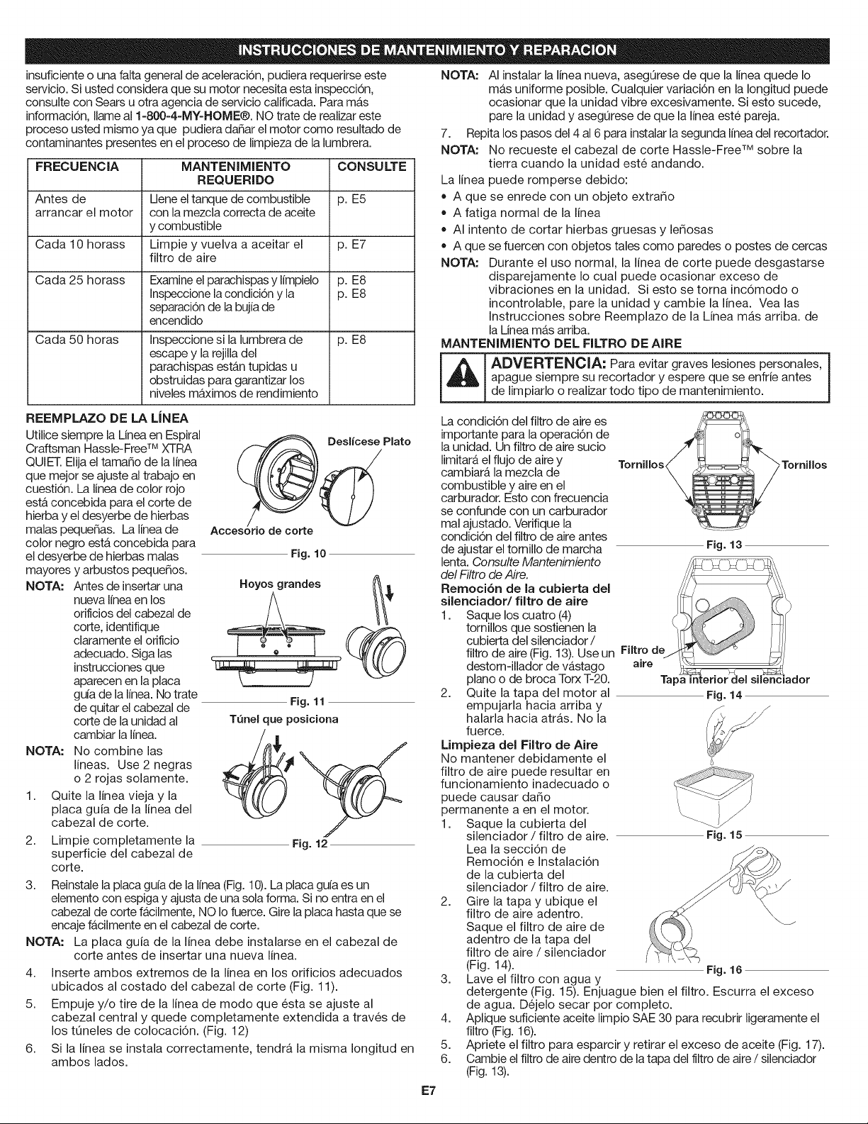
insuficiente o una falta general de aceleraci6n, pudiera requerirse este
servicio. Si usted considera que su motor necesita esta inspecci6n,
consulte con Sears u otra agenda de servicio calificada. Para mb,s
informaci6n, Ilame al 1-800=4-MY-HOME®. NO trate de realizar este
proceso usted mismo ya que pudiera da_ar el motor como resultado de
contaminantes presentes en el proceso de limpieza de la lumbrera.
FRECUENCIA MANTENIMIENTO CONSULTE
REQUERIDO
Antes de Uene el tanque de combustible p. E5
arrancar el motor con la mezcla correcta de aceite
y combustible
Cada 10 horass Limpie y vuelva a aceitar el p. E7
filtro de aire
Cada 25 horass Examineel parachispas y I{mpielo p. E8
Inspeccione la condici6n y la p. E8
separaci6n de la buj{ade
encendido
Cada 50 horas Inspeccione si la lumbrera de p. E8
escape y la rejilla del
parachispas estan tupidas u
obstruidas para garantizar los
niveles maximos de rendimiento
NOTA: AI instalar la linea nueva, asegQrese de que la linea quede Io
mas uniforme posible. Cualquier variaci6n en la Iongitud puede
ocasionar que la unidad vibre excesivamente. Si esto sucede,
pare la unidad y asegQrese de que la linea este pareja.
7. Repita los pasos del 4 al 6 para instalar la segunda Ifneadel recortador.
NOTA: No recueste el cabezal de corte Hassle-Free TM sobre la
tierra cuando la unidad este andando.
La linea puede romperse debido:
• A que se enrede con un objeto extrado
A fatiga normal de la linea
AI intento de cortar hierbas gruesas y ledosas
A que se fuercen con objetos tales como paredes o postes de cercas
NOTA: Durante el uso normal, la linea de corte puede desgastarse
disparejamente Io cual puede ocasionar exceso de
vibraciones en la unidad. Si esto se torna inc6modo o
incontrolable, pare la unidad y cambie la linea. Vea las
Instrucciones sobre Reemplazo de la Linea mas arriba, de
la Linea mas arriba.
MANTENIMIENTO DEL FILTRO DE AIRE
_ DVERTENClA: Para evitar graves lesiones personales,
apague siempre su recortador y espere que se enfrie antes
de limpiarlo o realizar todo tipo de mantenimiento.
REEMPLAZO DE LA LiNEA
Utilice siempre la Linea en Espiral
Craftsman Hassle-FreeTM XTRA
QUIE-i-.Elija el tamano de la linea
que mejor se ajuste al trabajo en
cuesti6n. La linea de color rojo
est,, concebida para el corte de
hierba y el desyerbe de hierbas
malas pequenas. La linea de
color negro est,, concebida para
el desyerbe de hierbas malas
mayores y arbustos pequenos.
NOTA: Antes de insertar una
nueva Ifneaen los
oriflcios del cabezal de
corte, identifique
claramente el oriflcio
adecuado. Siga las
instruccionesque
aparecen en la placa
gufa de la Ifnea. No trate
de quitar el cabezal de
corte de la unidad al
cambiar la Ifnea.
NOTA: No combine las
lineas. Use 2 negras
o 2 rojas solamente.
1. Quite la linea vieja y la
placa guia de la linea del
cabezal de corte.
Deslfcese Plato
Fig. 10
Hoyos grandes _
Fig. 11
Tenel que posiciona
2. Limpie completamente la
superficie del cabezal de
corte.
Fig. 12
3. Reinstale la placa guia de la linea (Fig. 10). La placa guia es un
elemento con espiga y ajusta de una sola forma. Si no entra en el
cabezal de corte facilmente, NO Io fuerce. Gire la placa hasta que se
encaje facilmente en el cabezal de corte.
NOTA: La placa guia de la linea debe instalarse en el cabezal de
corte antes de insertar una nueva linea.
4. Inserte ambos extremos de la linea en los orificios adecuados
ubicados al costado del cabezal de corte (Fig. 11).
5. Empuje y/o tire de la linea de modo que esta se ajuste al
cabezal central y quede completamente extendida a traves de
los tL_neles de colocaci6n. (Fig. 12)
6. Si la linea se instala correctamente, tendra la misma Iongitud en
ambos lados.
La condici6n del filtro de aire es
importante para la operaci6n de
la unidad. Un filtro de aire sucio
limitara el flujo de aire y
cambiara la mezcla de
combustible y aire en el
carburador. Esto con frecuencia
se confunde con un carburador
mal ajustado. Verifique la
condici6n del filtro de aire antes
de ajustar el tornillo de marcha
lenta. Consulte Mantenimiento
del Filtro de Aire.
Remoci6n de la cubierta del
sHenciador/filtro de aire
1. Saque los cuatro(4)
2.
TorniHos _Tornillos
tomillos que sostienen la
cubierta del silenciador /
filtro de aire (Fig. 13). Use un Filtro d_
destorn-illador de vastago
piano o de broca Torx -I--20.
Quite la tapa del motor al
empujarla hacia arriba y
halarla hacia atras. No la
fuerce.
Fig. 13
aire ._
Tapa interior del silenciador
Fig. 14
Limpieza del Filtro de Aire
No mantener debidamente el
filtro de aire puede resultar en
funcionamiento inadecuado o
puede causar daSo
permanente a en el motor.
1. Saque la cubierta del
silenciador / filtro de aire.
Lea la secci6n de
Remoci6n e Instalaci6n
de la cubierta del
silenciador / filtro de aire.
2. Gire la tapay ubique el
filtro de aire adentro.
Saque el filtro de aire de
adentro de la tapa del
filtro de aire / silenciador
(Fig. 14).
3. Lave el filtro con agua y
\ J
Fig. 15
Fig. 16
detergente (Fig. 15). Enjuague bien el filtro. Escurra el exceso
de agua. Dejelo secar por completo.
4. Aplique suficiente aceite limpio SAE 30 para recubrir ligeramente el
filtro (Fig. 16).
5. Apriete el filtro para esparcir y retirar el exceso de aceite (Fig. 17).
6. Cambie el filtro de aire dentro de la tapa del filtro de aire / silenciador
(Fig. 13).
E7
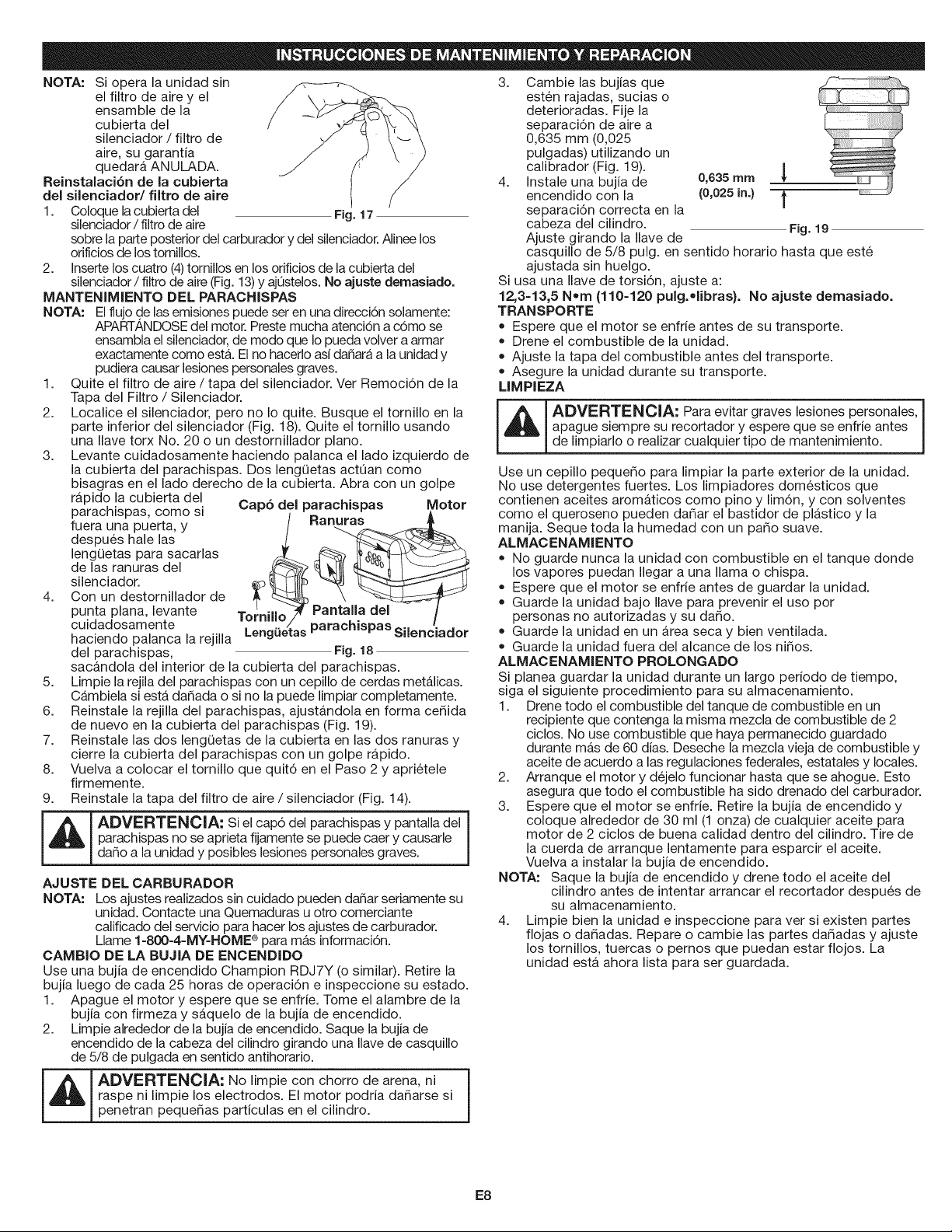
NOTA: Si opera la unidad sin
el filtro de aire y el
ensamble de la
cubierta del
silenciador / filtro de
aire, su garantia
quedara ANULADA.
Reinstalaci6n de la cubierta
del silenciador/filtro de aire
1. Coloque lacubierta del Fig. 17
silenciador/filtro de aire
sobre la parte posterior del carburador y del silenciador.Alinee los
orificios de lostornillos.
2. Inserte los cuatro (4)tornillos en losorificios de la cubierta del
silenciador / filtro de aire (Fig. 13)y ajOstelos. No ajuste dernasiado.
MANTENIMIENTO DEL PARACHISPAS
NOTA: El fiujo de las emisiones puede ser en una direcci6n solamente:
APARTANDOSEdel motor. Preste mucha atenci6n a c6mo se
ensambla el silenciador, de modo que Io pueda volver a armar
exactamente como estA. El no hacerlo asi da_arA a la unidad y
pudiera causar lesiones personales graves.
1. Quite el filtro de aire / tapa del silenciador. Ver Remoci6n de la
Tapa del Filtro / Silenciador.
2. Localice el silenciador, pero no Io quite. Busque el tornillo en la
parte inferior del silenciador (Fig. 18). Quite el tornillo usando
una Ilave torx No. 20 o un destornillador piano.
3. Levante cuidadosamente haciendo palanca el lado izquierdo de
la cubierta del parachispas. Dos lengQetas actOan como
bisagras en el lado derecho de la cubierta. Abra con un golpe
4.
rapido la cubierta del
parachispas, como si
fuera una puerta, y
despues hale las
lengQetas para sacarlas
de las ranuras del
silenciador.
Con un destornillador de
punta plana, levante
cuidadosamente
haciendo palanca la rejilla
del parachispas,
5.
6.
7.
8.
9.
Cap6 del parachispas Motor
./ Ran_.
r
Fig. 18
sacandola del interior de la cubierta del parachispas.
Limpie la rejila del parachispas con un cepillo de cerdas metalicas.
Cambiela siesta da_ada o si no la puede limpiar completamente.
Reinstale la rejilla del parachispas, ajustandola en forma ce_ida
de nuevo en la cubierta del parachispas (Fig. 19).
Reinstale las dos lengQetas de la cubierta en las dos ranuras y
cierre la cubierta del parachispas con un golpe rapido.
Vuelva a colocar el tornillo que quit6 en el Paso 2 y aprietele
firmemente.
Reinstale la tapa del filtro de aire / silenciador (Fig. 14).
ADVERTENCIA: si el cap6 del parachispas y pantalla del i
parachispas no se aprieta fijamente se puede caer y causarle
I
dano a la unidad y posibles lesiones personales graves.
AJUSTE DEL CARBURADOR
NOTA: Los ajustes realizados sin cuidado pueden danar seriamente su
unidad. Contacte una Quemaduras u otro comerciante
calificado del servicio para hacer los ajustes de carburador.
Llame 1-800-4-MY=HOME ® para mAs informaci6n.
CAMBIO DE LA BUJIA DE ENCENDIDO
Use una bujia de encendido Champion RDJ7Y (o similar). Retire la
bujia luego de cada 25 horas de operaci6n e inspeccione su estado.
1. Apague el motor y espere que se enfrie. Tome el alambre de la
bujia con firmeza y saquelo de la bujia de encendido.
2. Limpie alrededor de la bujia de encendido. Saque la bujia de
encendido de la cabeza del cilindro girando una Ilave de casquillo
de 5/8 de pulgada en sentido antihorario.
_ ADVERTENCIA: No limpie con chorro de arena, ni
raspe ni limpie los electrodos. El motor podria da5arse si
1penetran peque5as particulas en el cilindro.
3. Cambie las bujias que
esten rajadas, sucias o
deterioradas. Fije la
separaci6n de aire a
0,635 mm (0,025
pulgadas) utilizando un
calibrador (Fig. 19).
4. Instale una bujia de
encendido con la
separaci6n correcta en la
cabeza del cilindro.
Ajuste girando la Ilave de
Fig. 19
casquillo de 5/8 pulg. en sentido horatio hasta que este
ajustada sin huelgo.
Si usa una Ilave de torsi6n, ajuste a:
12,3=13,5 Nora (110-120 pulg.olibras). No ajuste demasiado.
TRANSPORTE
Espere que el motor se enfrie antes de su transporte.
• Drene el combustible de la unidad.
Ajuste la tapa del combustible antes del transporte.
Asegure la unidad durante su transporte.
LIMPIEZA
ADVERTENClA: Para evitar graves lesiones personales, 1
apague siempre su recortador y espere que se enfrie antes
de limpiarlo o realizar cualquier tipo de mantenimiento.
Use un cepillo pequedo para limpiar la parte exterior de la unidad.
No use detergentes fuertes. Los limpiadores domesticos que
contienen aceites aromaticos como pino y lim6n, y con solventes
como el queroseno pueden da_ar el bastidor de plastico y la
manija. Seque toda la humedad con un pado suave.
ALMACENAMIENTO
= No guarde nunca la unidad con combustible en el tanque donde
los vapores puedan Ilegar a una llama o chispa.
Espere que el motor se enfrie antes de guardar la unidad.
Guarde la unidad bajo Ilave para prevenir el uso por
personas no autorizadas y su daSo.
Guarde la unidad en un Area seca y bien ventilada.
Guarde la unidad fuera del alcance de los nidos.
ALMACENAMIENTO PROLONGADO
Si planea guardar la unidad durante un largo periodo de tiempo,
siga el siguiente procedimiento para su almacenamiento.
1. Drene todo el combustible del tanque de combustible en un
recipiente que contenga la misma mezcla de combustible de 2
ciclos. No use combustible que haya permanecido guardado
durante mas de 60 dias. Deseche la mezcla vieja de combustible y
aceite de acuerdo alas regulaciones federales, estatales y locales.
2. Arranque el motor y dejelo funcionar hasta que se ahogue. Esto
asegura que todo el combustible ha sido drenado del carburador.
3. Espere que el motor se enfrie. Retire la bujia de encendido y
coloque alrededor de 30 ml (1 onza) de cualquier aceite para
motor de 2 ciclos de buena calidad dentro del cilindro. Tire de
la cuerda de arranque lentamente para esparcir el aceite.
Vuelva a instalar la bujia de encendido.
NOTA: Saque la bujia de encendido y drene todo el aceite del
cilindro antes de intentar arrancar el recortador despues de
su almacenamiento.
4. Limpie bien la unidad e inspeccione para ver si existen partes
flojas o da_adas. Repare o cambie las partes da_adas y ajuste
los tornillos, tuercas o pernos que puedan estar flojos. La
unidad esta ahora lista para ser guardada.
E8
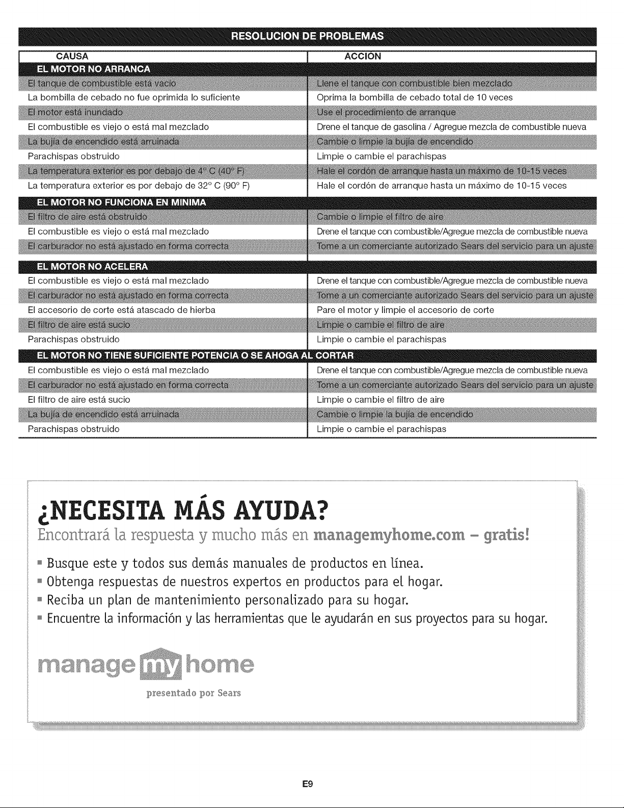
CAUSA
La bombilla de cebado no fue oprimida Io suficiente
El combustible es viejo o esta mal mezclado
Parachispas obstruido
La temperatura exterior es por debajo de 32 ° C (90° F)
El combustible es viejo o esta mal mezclado
El combustible es viejo o esta mal mezclado
El accesorio de corte esta atascado de hierba
Parachispas obstruido
ACCION
Oprima la bombilla de cebado total de 10 veces
Drene el tanque de gasolina / Agregue mezcla de combustible nueva
Limpie o cambie el parachispas
Hale el cord6n de arranque hasta un maximo de 10-15 veces
Drene el tanque con combustible/Agregue mezda de combustible nueva
Drene el tanque con combustibb/Agregue mezcla de combustible nueva
Pare el motor y limpie el accesorio de corte
Limpie o cambie el parachispas
El combustible es viejo o esta mal mezclado
El filtro de aire esta sucio
Parachispas obstruido
Drene el tanque con combustibb/Agregue mezcla de combustible nueva
Limpie o cambie el filtro de aire
Limpie o cambie el parachispas
£SITA AYUDA? o
EncontY_aY_a_a respuesta y mucho mas en maaagemyhOmeoCOla _ gratis:
o Busque este y to dos sus dem _s manua[es de pro ductos en [,nea.
o 0btenga respuestas de nuestros expertos en productos para e[ hogar.
o Redba un plan de mantenimiento persona[izado para su hogar.
o Encuentre [a informad6n y [as herramientas que [e ayudar_n en sus proyectos para su hogar.
E9
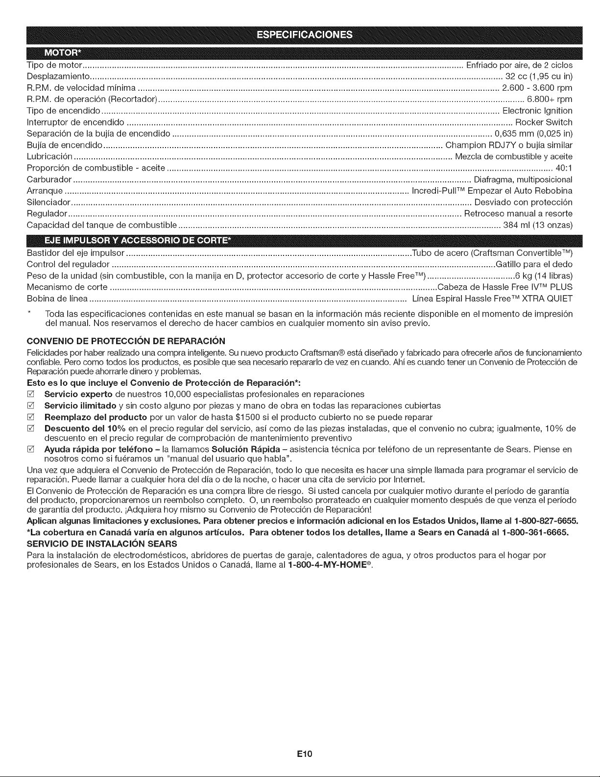
Tipo de motor ............................................................................................................................................................ Enfriado por aire, de 2 ciclos
Desplazamiento ......................................................................................................................................................................... 32 cc (1,95 cu in)
R.RM. de velocidad minima .................................................................................................................................................... 2.600 - 3.600 rpm
R.RM. de operaci6n (Recortador) ...................................................................................................................................................... 6.800+ rpm
Tipo de encendido ................................................................................................................................................................... Electronic Ignition
Interruptor de encendido .............................................................................................................................................................. Rocker Switch
Separaci6n de la bujia de encendido ................................................................................................................................... 0,635 mm (0,025 in)
Bujia de encendido ........................................................................................................................................... Champion RDJ7Y o bujia similar
Lubricaci6n ........................................................................................................................................................... Mezcla de combustible y aceite
Proporci6n de combustible - aceite .............................................................................................................................................................. 40:1
Carburador ................................................................................................................................................................... Diafragma, multiposicional
Arranque ............................................................................................................................................. Incredi-Pull TM Empezar el Auto Rebobina
Silenciador .................................................................................................................................................................... Desviado con protecci6n
Regulador ................................................................................................................................................................. Retroceso manual a resorte
Capacidad del tanque de combustible .................................................................................................................................... 384 ml (13 onzas)
Bastidor del eje impulsor ..................................................................................................................... Tubo de acero (Craftsman Convertible TM)
Control del regulador ............................................................................................................................................................. Gatillo para el dedo
Peso de la unidad (sin combustible, con la manija en D, protector accesorio de corte y Hassle Free TM) .................................... 6 kg (14 libras)
Mecanismo de corte ...................................................................................................................................... Cabeza de Hassle Free IW M PLUS
Bobina de linea .................................................................................................................................. Linea Espiral Hassle Free TM XTRA QUIET
* Toda las especificaciones contenidas en este manual se basan en la informaci6n mas reciente disponible en el momento de impresi6n
del manual. Nos reservamos el derecho de hacer cambios en cualquier momento sin aviso previo.
CONVENIO DE PROTECCION DE REPARACION
Felicidades por haber realizado una compra inteiigente.Su nuevo producto Craftsman® est#,dise_ado y fabricado para ofrecerle anos de funcionamiento
confiable. Pero como todos los productos, es posible que sea necesario repararlo de vez en cuando. Ahi es cuando tener un Convenio de Protecci6n de
Reparaci6n puede ahorrarle dinero y problemas.
Esto es Io que incluye el Convenio de Protecci6n de Reparaci6n*:
[] Servicio experto de nuestros 10,000 especialistas profesionales en reparaciones
[] Servicio ilimitado y sin costo alguno por piezas y mano de obra en todas las reparaciones cubiertas
[] Reemplazo del producto por un valor de hasta $1500 si el producto cubierto no se puede reparar
[] Descuento de110% en el precio regular del servicio, asi como de las piezas instaladas, que el convenio no cubra; igualmente, 10% de
descuento en el precio regular de comprobaci6n de mantenimiento preventivo
[] Ayuda rApida pot tel_fono - la Ilamamos Soluci6n RApida - asistencia tecnica por telefono de un representante de Sears. Piense en
nosotros como si fueramos un "manual del usuario que habla".
Una vez que adquiera el Convenio de Protecci6n de Reparaci6n, todo Io que necesita es hacer una simple Ilamada para programar el servicio de
reparaci6n. Puede Ilamar a cualquier hora del dia o de la noche, o hacer una cita de servicio por Internet.
El Convenio de Protecci6n de Reparaci6n es una compra libre de riesgo. Si usted cancela por cualquier motivo durante el periodo de garantia
del producto, proporcionaremos un reembolso completo. O, un reembolso prorrateado en cualquier momento despues de que venza el periodo
de garantia del producto, iAdquiera hoy mismo su Convenio de Protecci6n de Reparaci6n!
Aplican algunas limitaciones y exclusiones. Para obtener precios e informaci6n adicional en los Estados Unidos, llame al 1-800=827=6655.
*La cobertura en Canada varia en algunos articulos. Para obtener todos los detalles, llarne a Sears en Canada al 1-800-361-6665.
SERVIClO DE INSTALACION SEARS
Para la instalaci6n de electrodomesticos, abridores de puertas de garaje, calentadores de agua, y otros productos para el hogar por
profesionales de Sears, en los Estados Unidos o CanadA, Ilame al 1-800-4-MY-HOME ®.
EIO

DECLARACION DE GARANTJA DE CONTROL DE EMISIONES EVAPORATIVAS DE LA EPA PARA CALiFORNiA
Los Derechos y Obligaciones de Usted seg_n la Garant{a
El Consejo de Recursos del Aire (Air Resources Board) de California, la Agencia de Protecci6n del Medio Ambiente (EPA)y Sears, Roebuck and Co. (Sears)
tienen el placer de explicar la garantia del sistema de control de emisiones en su motor "off-road" peque_o modelo del ano 2008 y posterior. En California
y los 49 estados, los nuevos motores "off-road" peque_os deben set disenados, construidos y equipados para que cumplan con las exigentes normas del
Estado contra el "smog". Sears debe garantizar el sistema de control de emisiones en el motor "off-road" pequeno de usted para los pedodos de tiempo
que se indican a continuaci6n siempre y cuando no haya habido maltrato, negligencia o mantenimiento inadecuadode su motor "off-road" peque_o.
El sistema de usted de control de emisiones pudiera incluirpiezas tales como el carburador o sistema de inyecci6nde combustible, el sistema de encendido
y el convertidor catalftico. Tambien pudiera incluirmangueras, correas, conectores y otros conjuntos relacionados con las emisiones.
Cuando exista una condici6n que este dentro de la garantfa, Sears reparara su motor "off-road" peque_o sin costo alguno para usted, incluyendodiagn6stico,
piezas y mano de obra.
Los motores "off-road" peque_os de12007y posteriores estan garantizados pot dos a_os. Si alguna piezade su motor relacionadacon emisiones es defectuosa,
Sears la reparara o la reemplazara.
Responsabilidades del Propietario seg_n la Garant{a
Como propietario del motor "off-road" peque_o, usted es responsable de realizar el mantenimiento requerido que se indica en su manual del operador. Sears
recomienda que usted conserve todos los recibos que cubren el mantenimiento de su motor "off-road" peque_o, pero Sears no puede denegar la garantfa
solamente porque usted no tenga los recibos ni porque usted no pueda asegurar que se ha realizado todo el mantenimiento programado.
• Sin embargo, como propietario del motor "off-road" peque_o, usted debera estar consciente de que Sears pudiera denegarle cobertura de la garantfasi su
motor "off-road" peque_o o una piezadel mismo ha presentadofallas debido a maltrato,negligencia,mantenimientoinadecuadoo modificaciones no aprobadas.
• Usted es responsable de presentar su motor "off-road" peque_o a un Centro de Servicio Autorizado pot Sears tan pronto se detecte el problema. Las
reparaciones en garantfa deberan terminarse en un per{odo de tiempo razonable, no mayor de 30 dias.
Si tiene alguna pregunta en relaci6n con sus derechos y responsabilidades de acuerdo con su garantia, debera Ilamar al 1-800-4-MY=HOME ®.
Cobertura de la Garant{a del Fabricante
• El periodo de garantia comienza en la fecha en que se entrega el motor o el equipo al comprador del minorista.
• El fabricante garantiza al propietario inicial, y a cada comprador subsiguiente, por un periodo de dos aSos, que el motor no tiene defectos
en los materiales ni la mano de obra que ocasionen la falla de una pieza garantizada.
• La reparaci6n o el reemplazo de una pieza garantizada se realizara sin costo alguno para el propietario en un Centro de Servicio Autorizado
por Sears. Para conocer la ubicaci6n mas cercana comuniquese con Sears Ilamando al 1-800-4-MY-HOME ®.
• Cualquier pieza garantizada que no este programada para reemplazo, segun Io exige el mantenimiento, o que este programada solamente para inspecci6n
regular a los efectos de "Reparar o Reemplazar Segun sea Necesario" estb_garantizada por el perfodo de garantfa. Cualquier pieza garantizada que este
programada para reemplazo segun Io exige el mantenimiento, estara garantizada pot el per{odo de tiempo hasta el primer punto de reemplazo programado
para esa pieza.
• No se le cobrara al propietario pot el trabajo de diagn6stico que Ileve a la determinaci6n de que una pieza garantizada esta defectuosa, si el trabajo de
diagn6stico se Ileva a cabo en un Centro de Servicio Autorizado pot Sears.
• El fabricante es responsable de los da_os a otros componentes del motor causados pot la falla de una pieza garantizada que este todavia en garantia.
• Las fallas ocasionadas debido a maltrato, negligencia o mantenimiento inadecuadono estan cubiertas pot esta garantia.
• El uso de accesorios o piezas modificadas puede ser motivo para desestimar una reclamaci6n de garantia. Elfabricante no es responsable de cubrir fallas
de piezas garantizadas causadas pot el uso de accesorios o piezas modificadas.
• Para presentar una reclamaci6n, vaya a su Centro de Servicio Sears Autorizado mas cercano. Los servicios o reparaci6n pot motivo de garantia se
realizaranen todos los Centros de Servicio Sears Autorizados.
• Cualquier piezade reemplazo aprobada pot elfabricante se puede usar al realizarcualquier mantenimiento o reparaci6n de piezasbajo garantia relacionadas
con emisiones y se proporcionaran sin cargo alguno para el propietario. Cualquier pieza de reemplazo que sea equivalente en rendimiento o durabilidad
se puede usar en mantenimiento o reparaci6n sin garantia y no reducira las obligaciones de garantfa del fabricante.
Lista de Piezas de Emisiones en Garantia
Los siguientes componentes se incluyenen la garantfa del motor relacionada con emisiones: filtro de aire, carburador, cebador, tuber{as de combustible,
recuperaci6n de combustible/filtro de combustible, m6dulo de encendido, bujia y silenciador.
DECLARAClON DE GARANTJA DE CONTROL DE EMISIONES EVAPORATIVAS PARA CALIFORNIA
Los Derechos y Obligaciones de Usted seg_n la Garant{a
El Consejo de Recursos del Aire (Air Resources Board) de California y Sears, Roebuck and Co. (Sears)tienen el placer de explicar la garantia del sistema de
control de emisiones evaporativas en su motor "off-road" pequeSo (tipo de equipo) modelo del aSo 2007 y posterior. En California, los nuevos equipos que usen
motores "off-road" pequeSos deben set diseSados, construidos y equipados para que cumplan con las exigentes normas del Estado contra el "smog". Sears
debe garantizar el sistema de control de emisiones evaporativas en su motor "off-road" Lawn & Garden (para el cesped y el jardin) pequeSo para el per{odo
que se indicaa continuaci6n siempre y cuando no haya habido maltrato, negligencia o mantenimiento inadecuadode su equipo.
Su sistema de control de emisiones evaporativas pudiera incluir piezas tales como: carburadores, tanques de combustible, tuber{as de combustible, tapas de
combustible, valvulas, recipientes, filtros, mangueras de vapor, abrazaderas, conectores y otros componentes relacionados. En el caso de los motores de 80
cc o menos, solamente el tanque de combustiMe est_ sujeto a los requisitos de la garantia de control de emisiones evaporativas de esta secci6n. El
desplazamiento de su motor "off=road" peque5o es de menos de 80 cc.
Cobertura de la Garantia del Fabricante
Este sistema de control de emisiones evaporativas est& garantizado pot dos a_os. Si cualquier pieza relacionada con las emisiones evaporativas de su equipo
es defectuosa, la pieza sera reparada o reemplazada pot Sears.
Ell
ResponsabilidadesdelPropietarioseg_nlaGarantfa
• Como propietario del motor "off-road" Lawn & Garden pequeSo, usted es responsable de realizar el mantenimiento requerido que se indicaen su manual
de propietario. Sears recomienda que usted conserve todos los recibos que cubren el mantenimiento de su Motor Lawn & Garden, pero Sears no puede
denegar la garantia solamente porque usted no tenga los recibos.
• Sin embargo, como propietario del motor "off-road" Lawn & Garden pequeSo, usted debera estar consciente de que Sears pudiera denegarle cobertura
de la garantfasi su tanque de combustible ha presentado fallas debido a maltrato, negligencia, mantenimiento inadecuado o modificaciones no aprobadas.
• Usted es responsable de presentar su tanque de combustible Lawn & Garden al centro de distribuci6n o al centro de servicio de Searstan pronto se detecte
el problema. Las reparaciones en garantfa deberan terminarse en un periodo de tiempo razonable, no mayor de 30 dias. Si tiene alguna pregunta en
relaci6n con la cobertura de su garantia, debera comunicarse con Sears Ilamando al 1-800=4-MY-HOME ®.
Requisitos de la Garantfa per Defectos
(a) El perfodo de garantfa comienza en la fecha en que se entrega el motor o el equipo a un comprador final.
(b) Cobertura General de la Garantia de Emisiones Evaporativas. Eltanque de combustible debe estar garantizado al comprador final y a cualquier propietario
posterior en cuanto a que cuando se instal6 el sistema de control de emisiones evaporativas estaba:
(1) DiseSado, construido y equipado de forma tal que cumpl[a con todas la regulaciones aplicables; y
(2) Sin defectos en los materiales ni la mano de obra que ocasionen la falla de una pieza garantizada durante un periodo de dos aSos.
(c) La garantia de las piezas relacionadas con las emisiones evaporativas sera interpretada como sigue:
(1) Cualquier pieza garantizada que no este programada para reemplazo segun requiere el mantenimiento en las instrucciones pot escrito, debe estar
garantizada por el periodo de garantia definido en la subsecci6n (b)(2).Si alguna de esaspiezas falla durante el perfodo de cobertura de lagarantia, debe
set reparada o reemplazada por Sears. Cualquier pieza reparada o reemplazada bajo la garantia debe estar garantizada pot un tiempo no menor que
el periodo de garantia restante.
(2) Cualquier pieza garantizada que en las instrucciones por escrito este programada solamente para inspecci6n regular,debe estar garantizada por el
perfodo de garantia definido en la subsecci6n (b)(2).Una declaraci6n en dichas instrucciones por escrito al efecto de "reparar o reemplazar segun sea
necesario" no reducira el pen'odo de cobertura de la garantia. Cualquier pieza reparada o reemplazada bajo la garantia debe estar garantizada por un
tiempo no menor que el per[odo de garantfa restante.
(3) Cualquier pieza garantizada que este programada para reemplazo, segun exige el mantenimiento en lasinstrucciones por escrito, debe estar garantizada
por el per[odo de tiempo anterior al primer punto de reemplazo programado para esa pieza. Si la piezafalla antes del primer reemplazo programado, la
piezadebe set reparada o reemplazapor Sears. Cualquier pieza reparadao reemplazada bajo la garantiadebe estar garantizada pot un tiempo no menor
que Io que resta del periodo anterior al primer punto de reemplazo programado para esa pieza.
(4) La reparaci6n o el reemplazo de cualquier pieza garantizada bajo las disposiciones de garantia de este articulo se debe realizar sin costo alguno para
el propietario en una estaci6n donde se hagan trabajos de garantia.
(5) Independientemente de las disposiciones de la subsecci6n (4) anterior, los servicios o reparaciones en garantia se deben proporcionar en centros de
distribuci6n que esten franquiciados para prestar servicios a los motores o equipos en cuesti6n.
(6) No se debe cobrar al propietario por el trabajo de diagn6stico para determinar que una pieza garantizada esta realmente defectuosa, siempre y cuando
dicho trabajo de diagn6stico se Ileve a cabo en una estaci6n donde se hagan trabajos de garantia.
(7) Durante el periodo de garantia del sistema de control de emisiones evaporativas establecido en lasubsecci6n (b)(2),Sears debe mantener unsuministro
de piezas garantizadas suficiente para satisfacer la demanda esperada de dichas piezas.
(8) AI realizar cualquier mantenimiento o reparaci6n en garantia se deben usar piezas de reemplazo aprobadas por el fabricante y se deben proporcionar
sin cargo alguno para el propietario. Tal uso no reducira las obligaciones de garantia del fabricante que emite la garantfa.
(9) El uso de cualquier accesorio o pieza modificada sera motivo para desestimar una reclamaci6n de garantfa hecha en conformidad con este articulo. El
fabricante que emite la garantia no sera responsable, segun este Articulo, de garantizar fallas de piezas garantizadascausadas por el uso de un accesorio
o una pieza modificada.
(10) Sears proporcionara los documentos que describen los procedimientos o normas de la garantia, en un plazo de cinco dias habiles desde que los solicite
el Consejo de Recursos del Aire.
Lista de Piezas de Emisiones en Garantia
(1) Tanque de Combustible
Con cada motor o equipo nuevo se proporcionaran instrucciones por escrito para el mantenimiento y uso del sistema de control de emisiones evaporativas
por parte del propietario.
E12

E13

REPLACEMENT PARTS - MODEL 316.791900
2-CYCLE GAS TRIMMER
item Part No.
1 753-05214
2 791-180350B
3 791-180351
4 753-05216
5 753-05215
6 791-610675
7 791-181860
8 791-683974B
9 753-05217
10 791-684451
11 753-05487
12 791-612134
13 753-04606
14 791-182612
15 791-181086
16 753-05219
17 791-145308
18 753-05091
19 753-05240
20 791-181525
21 753-05221
22 753-05769
23 791-182396
Description item Part No.
Air Cleaner Assembly (includes 2 & 27) 24 791-182369
Air Cleaner Filter 25 791-153592
Carburetor Mounting Screw Assembly 26 753-04497
Choke Plate 27 791-181345
Carburetor Assembly (includes 6 & 16) 28 791-182519
Carburetor Gasket 29 753-04003
Carb Mount Screw 30 791-180217
Primer and Hose Assembly 31 753-05025
Carb Mount Assembly (includes 7, 10 & 11) 32 753-05226
Reed Assembly 33 791-610311B
Carburetor Mount Gasket 34 753-05169
Rear Mounting Pad 35 753-04619
Fuel Tank Assembly (includes 14-16) 36 753-04620
Fuel Cap Assembly 37 753-04814
Fuel Return Line 38 753-04367
Fuel Line Assembly 39 753-04182
Front Mounting Pad 40 791-182723
Shroud Extension & Stand (includes 27) 41 753-05222
Flywheel Assembly 42 791-182474
Spacer * 753-1209
ACL Lever Assembly * 753-05227
Starter Housing Assembly (includes 21,41 & 42)
Clutch Washer * 791-181599
Description
Clutch Rotor Assembly
Clutch Drum Assembly
Clutch Cover Assembly (includes 27-30)
Cover Screw
Anti-Rotation Screw
Clamping Screw
Clamping Nut
Wire Leads and Sleeve
Module Assembly
Spark Plug
Muffler Assembly (includes 35 & 36)
Exhaust Gasket
Muffler Mounting Bolt Assembly
Cylinder Assembly (includes 39 & 40)
Piston and Rod Assembly
Cylinder Gasket
Cylinder Bolt
ACL Throttle Cable
ACL Screw
Piston Ring Set
Short Block Assembly
(includes 7, 19, 20, 33 & 37-40)
Clutch Springs (Qty. 2)
* Items Not Shown
E14
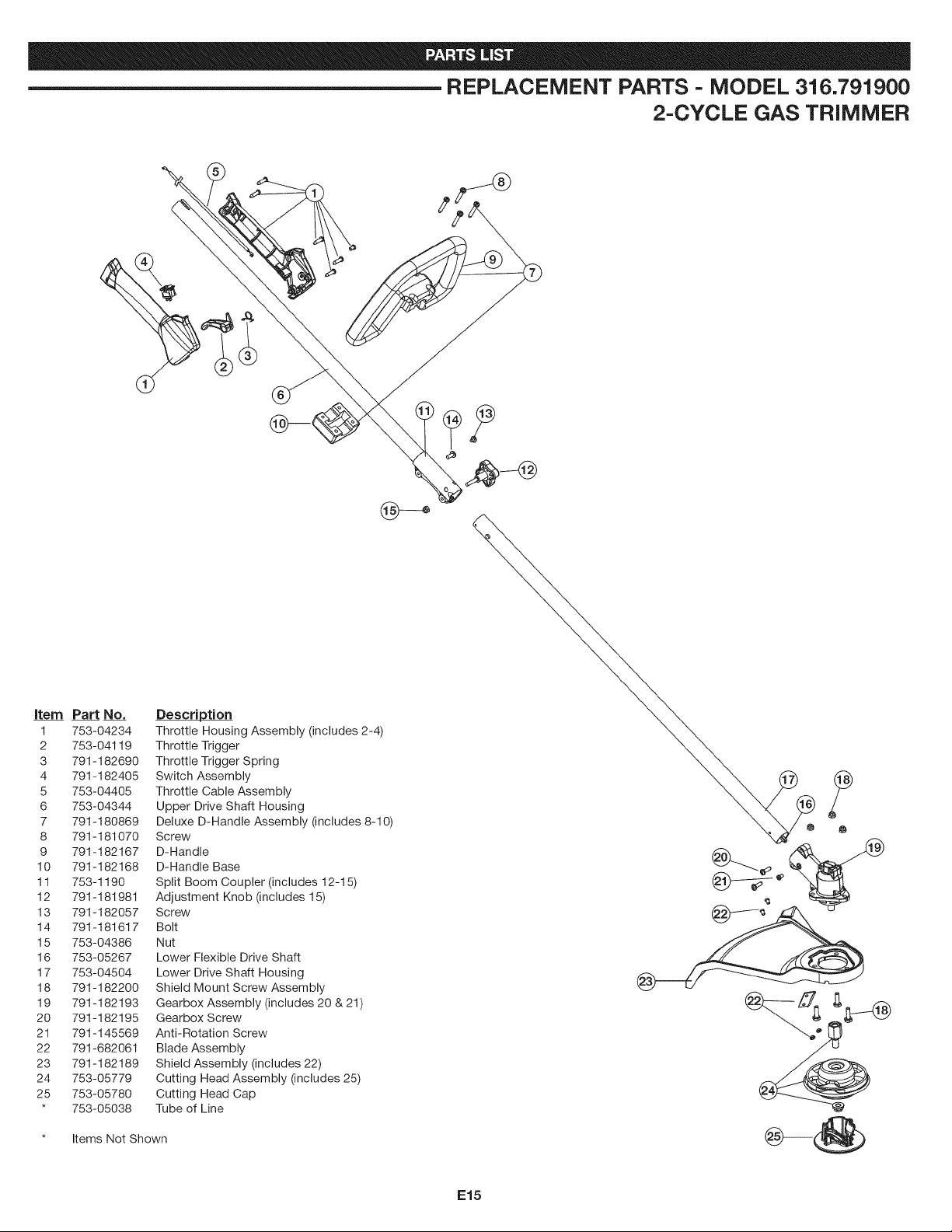
REPLACEMENT PARTS - MODEL 316.791900
2-CYCLE GAS TRIMMER
item Part No.
1 753-04234
2 753-04119
3 791-182690
4 791-182405
5 753-04405
6 753-04344
7 791-180869
8 791-181070
9 791-182167
10 791-182168
11 753-1190
12 791-181981
13 791-182057
14 791-181617
15 753-04386
16 753-05267
17 753-04504
18 791-182200
19 791-182193
20 791-182195
21 791-145569
22 791-682061
23 791-182189
24 753-05779
25 753-05780
* 753-05038
Description
Throttle Housing Assembly (includes 2-4)
Throttle Trigger
Throttle Trigger Spring
Switch Assembly
Throttle Cable Assembly
Upper Drive Shaft Housing
Deluxe D-Handle Assembly (includes 8-10)
Screw
D-Handle
D-Handle Base
Split Boom Coupler (includes 12-15)
Adjustment Knob (includes 15)
Screw
Bolt
Nut
Lower Flexible Drive Shaft
Lower Drive Shaft Housing
Shield Mount Screw Assembly
Gearbox Assembly (includes 20 & 21)
Gearbox Screw
Anti-Rotation Screw
Blade Assembly
Shield Assembly (includes 22)
Cutting Head Assembly (includes 25)
Cutting Head Cap
Tube of Line
* Items Not Shown
E15

Your Home
For expert troubleshooting and home solutions advice:
anage
@11
www.managemyhome.com
For repair - in your home - of all major brand appliances,
lawn and garden equipment, or heating and cooling systems,
no matter who made it, no matter who sold it!
For the replacement parts, accesspries and
owner's manuals that you need to do=it=yourself.
For Sears professional installation of home appliances
and items like garage door openers and water heaters.
1-800-4-MY-HOME ® (1-8oo-4o9-4oo3)
Call anytime, day or night (U.S.A. and Canada)
www.sears.com www.sears.ca
Our Home
For repair of carry-in items like vacuums, lawn equipment,
and electronics, call anytime for the location of your nearest
Sears Parts & Repair Service Center
1-800-488-1222 (U.S.A.) 1-800-469-4663 (Canada)
www.sears.corn www.sears.ca
To purchase a protection agreement on a product serviced by Sears:
1-800-827-6655 (U.S.A.) 1-800-361-6665 (Canada)
Para pedir servicio de reparaci6n Au Canada pour service en fran(_ais:
a domicilio, y para ordenar piezas: 1-800-LE=FOYER Mc
1-800-SU-HOGAR ® (1-800-533-6937)
(1-888-784-6427) www.sears.ca
SM
® Registered Trademark / TMTrademark / Service Mark of Sears Brands, LLC
® Marca Registrada / TMMarca de F&brica / SMMarca de Servicio de Sears Brands, LLC
MCMarque de commerce / MDMarque d6pos6e de Sears Brands, LLC © Sears Brands, LLC

