
SWAINS
[
IIFTSMIIN+
MODEL NUMBER 917.251471
OWNER'S MANUAL
+Assembly
• Operation
• Customer Responsibilities
+Service and Adjustments
+Repair Parts
CAUTION: Read and follow all safety rules and instructions before operating this equipment.
FOR CONSUMER ASSISTANCE HOT LINE, CALL THIS TOLL FREE NUMBER: 1-800-659-5917
A SAFETY RULES
Safe Operation Practices for Ride-On Mowers
IMPORTANT: THIS CUTTING MACHINE IS CAPABLE OFAMPUTATING HANDS AND FEET AND THROWING OBJECTS.
FAILURE TO OBSERVE THE FOLLOWING SAFETY INSTRUCTIONS COULD RESULT IN SERIOUS INJURY OR DEATH.
GENERAL OPERATION
Read, understand, and follow al! instructions in the manual
and on the machine before starting.
OnIy allow responsible adults, who are familiar with the
instructions, to operate the machine.
Clear the area of objects such as rocks, toys, wire, etc.,
which could be picked up and thrown by the blade.
Besure the area isclear of other people before mowing, Stop
machine if anyone enters the area.
Never carry passengers.
Do not mow in reverse unless absolutely necessary. Always
took down and behind before and while backing.
Be aware of the mower discharge direction and do not point
it at anyone. Do not operate the mower without either the
entire grass catcher or the guard in place.
Slow down before turning.
Never leave a running machine unattended. Always turn off
blades, set parking brake, stop engine, and remove keys
before dismounting.
Turn off blades when not mowing.
Stop engine before removing grass catcher or unclogging
chute.
Mow only in daylight or good artificial light,
Do not operate the machine while under the influence of
alcohol or drugs.
Watch for traffic when operating near or crossing roadways.
Use extra care when loading or unloading the machine into
a trailer or truck.
II. SLOPE OPERATION
Slopes are a major factor related to loss-of-control and
tipover accidents, which can result in severe injury ordeath.
All slopes require extra caution. If you cannot back up the
slope or if you feel uneasy on it, do not mow it.
DO:
Mow up and down slopes, not across.
Remove obstacles such as rocks, tree limbs, etc.
Watch for holes, ruts, or bumps. Uneven terrain could
overturn the machine. Tall grass can hide obstacles.
Use slow speed. Choose a low gear so that you will not have
to stop or shift while on the slope.
Follow the manufacturer's recommendations for wheel
weights or counterweights to improve stability.
Use extra care with grass catchers or other attachments.
These can change the stability of the machine.
Keep all movement on the slopes slowand gradual Do not
make sudden changes in speed or direction.
Avoid starting or stopping on a slope. If tires lose traction,
disengage the blades and proceed slowly straight down the
slope.
DO NOT:
Do not turn on slopes unless necessary, and then, turn slowly
and gradually downhill, if possible.
Do notmow near drop-offs, ditches, or embankments. The
mower could suddenly turn over if a wheel is over the edge
of a cliff or ditch, or if an edge caves in.
Do not mow on wet grass. Reduced traction could cause
sliding.
Do not try to stabilize the machine by putting your foot on the
ground.
Do not use grass catcher on steep slopes.
III. CHILDREN
Tragic accidents can occur if the operator is not alert to the
presence of children. Children are often attracted to the
machine and the mowing activity. Never assume that
children will remain where you last saw them.
Keep children out of the mowing area and under the watchful
care of another responsible adult.
Be alert and turn machine off if children enter the area.
Before and when backing, look behind and down for small
children.
, Never carry children. They may fall off and be seriously
injured or interfere with safe machine operation.
Never allow children to operate the machine.
Use extra care when approaching blind corners, shrubs,
trees, or other objects that may obscure vision.
IV. SERVICE
Use extra care in handling gasoline and other fuels. They are
flammable and vapors are explosive.
Use only an approved container.
Never remove gas cap or add fuel with the engine
running. Allow engine to cool before refueling. Do not
smoke.
Never refuel the machine indoors.
Never store the machine or fuel container inside where
there is an open flame, such as a water heater.
Never run a machine inside a closed area.
Keep nuts and bolts, especially blade attachment bolts, tight
and keep equipment in good condition,
Never tamper with safety devices. Check their proper
operation regularly.
Keep machine free of grass, leaves, or other debris build-up.
Clean oil or fuel spillage. Allow machine to cool before
storing.
Stop and inspect the equipment if you strike an object.
Repair, if necessary, before restarting.
Never make adjustments or repairs with the engine running.
Grass catcher components are subject to wear, damage, and
deterioration, which could expose moving parts or allow
objects to be thrown. Frequently check components and
replace with manufacturer's recommended parts, when nec-
essary.
Mower blades are sharp and can cut. Wrap the blade(s) or
wear gloves, and use extra caution when servicing them.
Check brake operation frequently. Adjust and service as
required.
A
Look for this symbol to point out im-
portant safety precautions. It means
CAUTION!!! BECOMEALERT!!! YOUR
SAFETY IS INVOLVED,
A
CAUTION: Always disconnect spark plug
wire and place wire wh ere it cannot contact
spark plug in order to prevent accidental
starting when setting up, transporting,
adjusting or making repairs.
2
A WARNING A
The engine exhaust from this product con-
tains chemicals known to the State of Califor-
nia to cause cancer, birth defects, or other
reproductive harm.
CONGRATULATIONS on your purchase of a Sears
Tractor. It has been designed, engineered and manufac-
tured to gwe you the best possible dependability and
performance.
Should you experience any problem you cannot easily
remedy, please contact your nearest Sears Authorized
Service Center/Department. We have competent, wel!-
trained technicians and the proper tools to service or repair
this tractor.
Please read and retain this manual. The instructions wili
enable you to assemble and maintain your tractor properly.
Always observe the "SAFETY RULES",
MODEL
NUMBER 917.251471
SERIAL
NUMBER
)ATEOF PURCHASE
THE MODELAND SERIAL NUMBERS WILL BE FOUND
ON A PLATE UNDER THE SEAT.
YOU SHOULD RECORD BOTH SERIAL NUMBER AND
DATE OF PURCHASE AND KEEP IN A SAFE PLACE
FOR FUTURE REFERENCE.
MAINTENANCE AGREEMENT
A Sears Maintenance Agreement is available on this prod-
uct. Contact your nearest Sears store for details,
CUSTOMER RESPONSIBILITIES
Read ana observe the safety rules.
Fol!ow a regularschedule in maintaining, canng for and
using your tractor.
Follow the instructions under "Customer Responsibili-
ties" and "Storage" sections of this owner's manual.
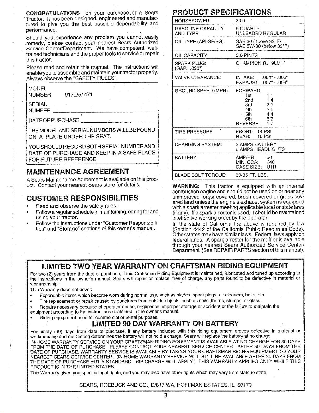
PRODUCT SPECiFiCATiONS
HORSEPOWER: 20.0
GASOLINE CAPACITY 5 QUARTS
AND TYPE: UNLEADED REGULAR
OIL TYPE _API-SF/SG, SAE 30 above 32°F_
SAE 5W-30 (below 32°Fj
OIL CAPACITY: 3.0 PINTS
SPARK PLUG: CHAMPION RJ19LM
(GAP: 030"/
VALVE CLEARANCE: INTAKE .004" - .006'
EXHAUST: .007" - .009'
GROUND SPEED I V1PH_: FORWARD:
I sl 1."
2rid 1.4
3rd 2.3
4th 3.5
5th 4.4
6th 5.7
REVERSE: 1.7
TIRE PRESSURE: FRONT: 14 PSi
REAR: 10 PSi
CHARGING SYSTEM: 3 AMPB BATTERY
5 AMPS HEADLIGHTS
BATTERY: AMP/HR: 30
MIN. CCA: 240
CASE SIZE: UtR
BLADE BOLT TORQUE: 30-35 FT. LBS.
WARNING: This tractor is equippea with an interne
combustion engine and should not be used on or near any
unimproved forest-covered brush-covered or grass-cov-
ered land unless the engine's exhaust system is equipped
with a spark arrester meeting applicable local or state laws
(if any). If a spark arrester is used, it should be maintained
in effective working order by the operator.
In the state of California the above is required by law
(Section 4442 of the California Public ResourcesCode).
Other states may have similar laws. Federal laws apply on
federal lands. A soark arrester for the muffler is available
through your nearest Sears Authorized Service Center/
Department (See REPAIR PARTS section of this manual).
LIMITED TWO YEAR WARRANTY ON CRAFTSMAN RIDING EQLIIPMENT
For two (2) years from the date el purchase, if this Craftsman Riding Equipment is maintained ubricated and tuned up according to
the instructions _nthe owner's manual Sears will repair or replace, free of charge, any parts found to be defective in material or
workmanship.
This Warranty does not cover:
Expendable items which become worn during normal use. such as blades, spark plugs, air cleaners, belts, etc
Tire replacement or repair caused by punctures from outside objects, such as nails, thorns, stumps, or glass.
Repairs necessary because of operator abuse, negligence, improper storage or accident or the failure to maintain the
equipment according to the instructions contained in the owner's manual.
Riding equipment used for commercial or rental purposes
LIMITED 90 DAY WARRANTY ON BATTERY
For nmety (90/ days from date of purchase, if any battery included with this riding equipment proves defective in material or
workmanship and our teshng determines the battery will not hold a charge Sears will replace the battery at no charge
IN-HOME WARRANTY SERVICE ON YOUR CRAFTSMAN RIDING EQUIPMENT IS AVAILABLE AT NO-CHARGE FOR 30 DAYS
:ROM THE DATE OF PURCHASE. PLEASE CONTACT YOUR NEAREST SERVICE CENTER AFTER 30 DAYS FROM THE
DATE OF PURCHASE. WARRANTY SERVICE IS AVAILABLE BY TAKING YOUR CRAFTSMAN RIDING EQUIPMENT TO YOUR
NEAREST SEARS SERVICE CENTER. ! N-HOME WARRANTY SERVICE WILL STILL BE AVAILABLE AFTER 30 DAYS FROM
THE DATE OF PURCHASE BUT A STANDARD TRIP CHARGE WILL APPLY.) THIS WARRANTY APPLIES ONLY WHILE THIS
PRODUCT IS IN THE UNITED STATES.
This Warranty gives you specific legal rights, and you may also have other rights which may vary from state to state.
SEARS, ROEBUCK AND CO. D/817 WA, HOFFMAN ESTATES, IL 60179
3
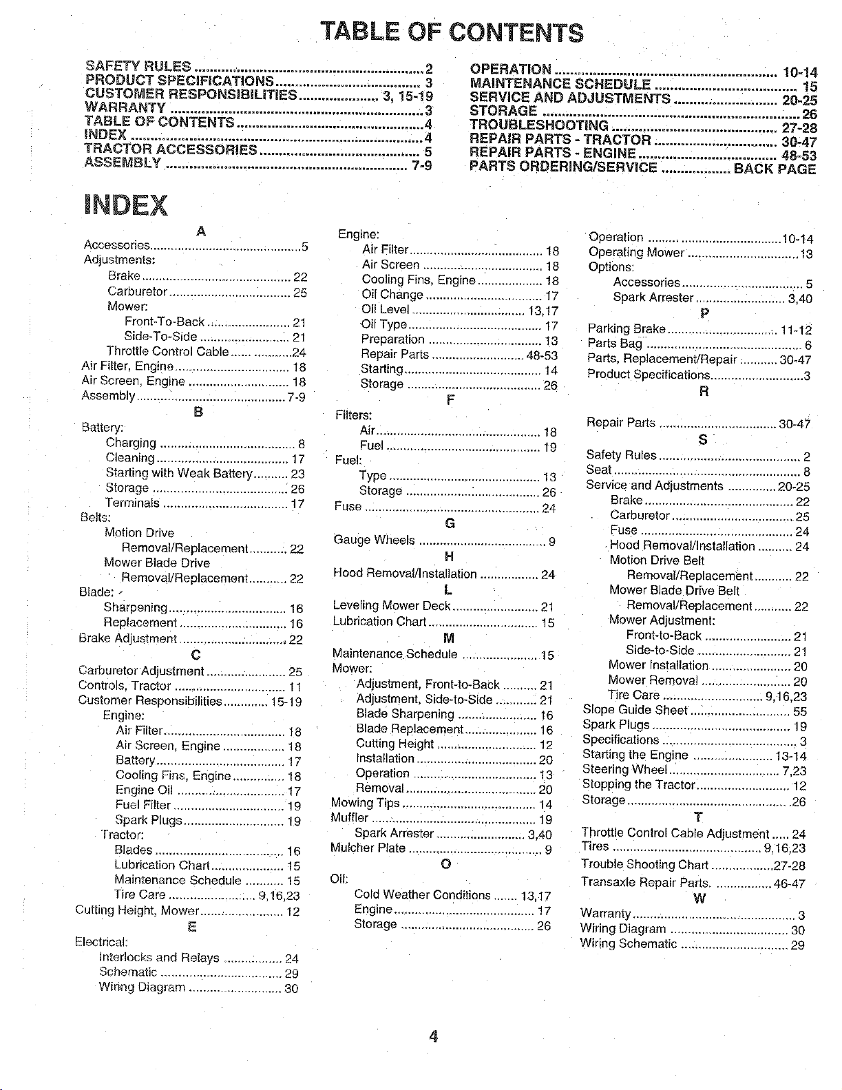
TABLE OF CONTENTS
SAFETY RULES ............................................................ 2
PRODUCT SPECIFICAT_ONS ...................................... 3
CUSTOMER RESPONSiBILiTIES ..................... 3. 15-19
WARRANTY .................................................................. 3
TABLE OF CONTENTS ................................................. 4
iNDEX ............................................................................ 4
TRACTOR ACCESSORIES .......................................... 5
ASSEMBLY ............................................................... 7-9
OPERATION .......................................................... 10=14
MAINTENANCE SCHEDULE ..................................... 15
SERVICE AND ADJUSTMENTS ........................... 20-25
STORAGE ................................................................... 26
TROUBLESHOOTING ........................................... 27-28
REPAIR PARTS - TRACTOR ................................ 30-47
REPAIR PARTS - ENGINE .................................... 48-53
PARTS ORDERING/SERVICE .................. BACK PAGE
mNOE×
A
Accessories ........................................... 5
Adjustments:
Brake ........................................... 22
Carburetor .................................. 25
Mower:
Front-To-Back ........................ 21
Side-To-Side .......................... 21
Throttle Control Cable ................. 24
Air Filter. Engine ................................. 18
Air Screen Engine ............................. 18
Assembly ........................................... 7-9
B
Battery:
Charging ..................................... 8
Cleaning ..................................... 17
Starting with Weak Battery .......... 23
Storage ....................................... 26
Terminals ................................... 17
Belts:
Motion Drive
Removal/Replacement .......... 22
Mower Blade Drive
_emoval/Replacement ........... 22
Blade:
Sharpening .................................. 16
Replacement .............................. 16
Brake Adjustment ............................... 22
c
Carburetor Adjustment ....................... 25
Controls. Tractor ................................ 11
Customer Responsibilities ............ 15-19
Engine:
Air Filter ................................... 18
Air Screen. Engine .................. 18
Battery ..................................... ! 7
Cooling Fins, Engine ............... 18
Engine Oil ............................... t7
Fuel Filter ............................... 19
Spark Plugs ............................. 19
Tractor:
Blades ..................................... 16
Lubrication Char'[ ..................... 15
Maintenance Schedule ........... 15
Tire Care ......................... 9.16.23
Cutting Height, Mower ..................... 12
E
Electrical:
Interlocks and Relays ................. 24
Schematic ................................ 29
Wirk'_gDiag r_.m ........................... 30
Engine:
Air Filter ....................................... 18
Air Screen ................................. 18
Cooling Fins, Engine .................. 18
Oil Change .................................. 17
Oil Level ................................ 13.17
Oil Type ....................................... 17
Prauaration ................................. 13
Repair Parts ........................... 48-53
Starting ........................................ 14
Storage ..................................... 26
F
Filters:
Air............................................... 18
Fuel ............................................ 19
Fuel:
Type ............................................ 13
Storage ....................................... 26
Fuse ................................................... 24
G
Gauge Wheels ..................................... 9
H
Hood Removal/Installation ................. 24
L
Leveling Mower Deck ......................... 2"
Lubrication Chart ............................... ! 5
M
Maintenance Schedule ..................... 15
Mower:
Adjustment, Front-to-Back .......... 21
Adjustment. Side-to-Side ............ 21
Blade Sharpening ....................... 16
Blade Replacemem .................... 16
Cutting Height ............................. 12
Installation ................................... 20
Operation .................................... 13
Removal ...................................... 20
Mowing Tips ....................................... 14
Muffler ................................................ 19
Spark Arrester ......................... 3.40
Mulcher Plate ....................................... 9
O
Oil:
Cold Weather Conditions ....... 13.17
Engine ......................................... !7
Storage ...................................... 26
Operation ...................................... 10-14
Operating Mower ................................ 13
Options:
Accessories ................................... 5
Spark Arrester .......................... 3.40
P
Parking Brake ................................ 11-12
Parts Bag ............................................. 6
Parts. Replacement/Repair ........... 30-47
Product Specifications ........................... 3
R
Repair Parts .................................. 30-47
S
Safety Rules ......................................... 2
Seat ..................................................... 8
Service and Adjustments .............. 20-25
Brake .......................................... 22
Carburetor ................................... 25
Fuse ............................................ 24
Hood Removal/Installation .......... 24
Motion Drive Belt
Removal/Reclacement ........... 22
Mower Blade Drive Belt
Removal/Replacement ........... 22
Mower Adjustment:
Front-to-Back ......................... 21
Side-to-Side ........................... 21
Mower Installation ...................... 20
Mower Removal ......................... 20
Tire Care ............................. 9.16.23
Slope Guide Sheet ............................ 55
Spark Plugs ........................................ 19
Specifications ....................................... 3
Starting the Engine ....................... 13-14
Steering Wheel ................................ 7.23
Stopping the Tractor ......................... 12
Storage ............................................... 26
T
Throttle Control Cable Adjustment ..... 24
Tires ......................................... 9.16.23
Trouble Shooting Chart ............... 27-28
Transaxle Repair Parts ................. 46-47
W
Warranty ............................................... 3
Wiring Diagram ................................. 30
Wiring Schematic .......................... 29
4
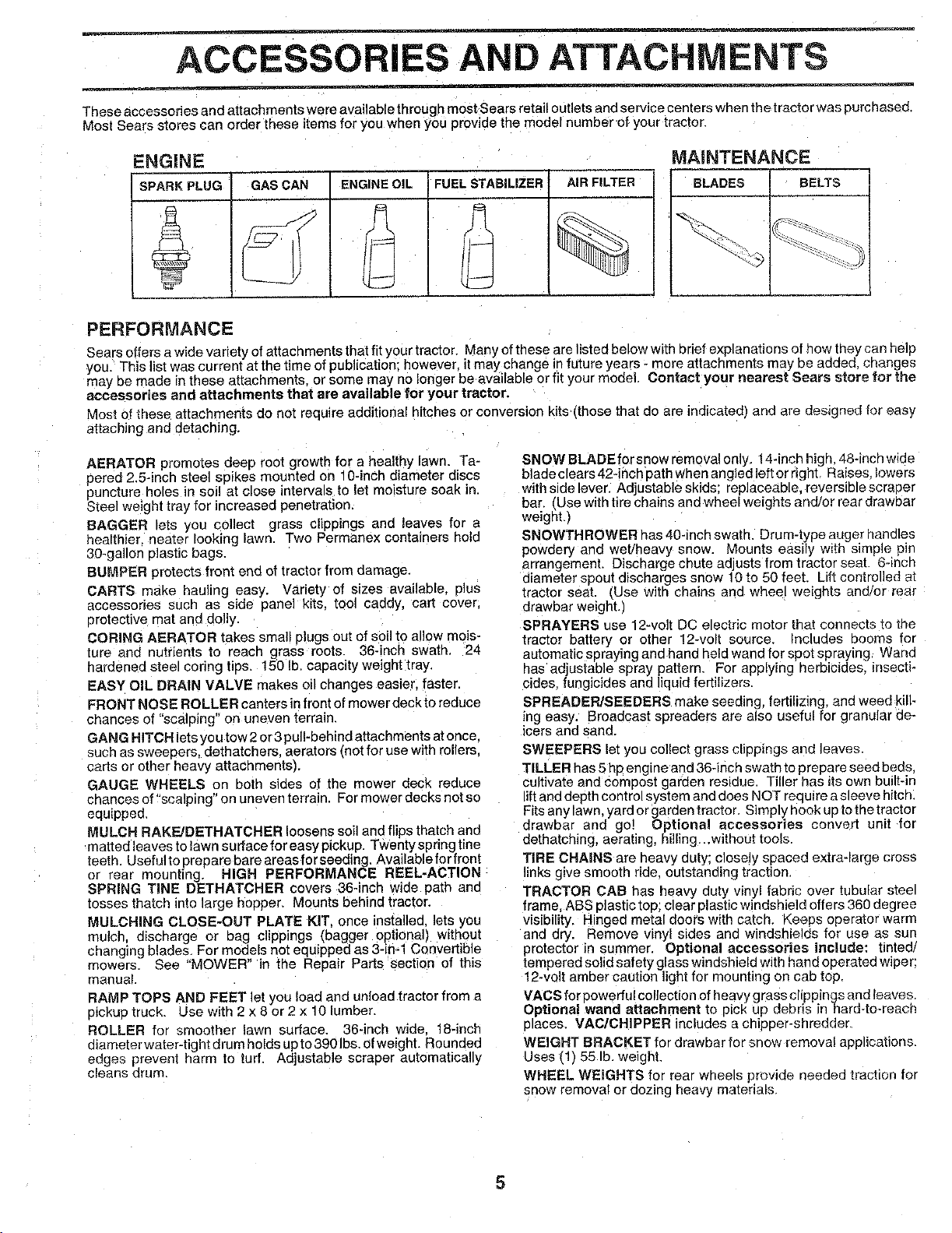
ACCESSORIES AND ATTACHMENTS
These accessories and attachments were available through most Sears retail outlets and service centers when the tractor was purchased.
Most Sears stores can order these items for you when you provide the model number of your tractor.
ENGINE MAINTENANCE
_,RKPLUG GAS CAN ENGINE OIL FUEL STABILIZER AIR FILTER BLADES BELTS
;t
PERFORMANCE
Sears offers a wide variety of attachments that fit your tractor. Many of these are listed below with brief exp=anations of how they can help
you. This list was current at the time of publication; however, it may change in future years - more attachments may be added, changes
may be made in these attachments, or some may no longer be available or fit your model Contact your nearest Sears store for the
accessories and attachments that are available for your tractor.
Most of these ar[achments do not require additional hitches or conversion kits tthose that do are indJcated_ and are designed for easy
attaching and detaching.
AERATOR promotes deep root growth for a healthy lawn, Ta-
nered 2.5-inch steel spikes mounted on 10-inch diameter discs
puncture holes in soil at close intervals to let moisture soak in.
Steel weight tray for increased penetration.
BAGGER ets you collect grass clippings and leaves for a
healthie[ o_ater looking lawn. Two Permanex containers hold
30-gallon plastic bags
BUMPER protects front end of tractor from damage.
CARTS make hauling easy. Variety of sizes available, e]us
accessories such as side pane] kits. tool caddy, cart cover.
erotectwe mat and oolly.
CORING AERATOR takes small plugs out of soil to allow mois-
ture and nutrients to reach grass roots. 36-inch swath. 24
hardened steel coring tips. !50 lb. capacity weight tray.
EASY OIL DRAIN VALVE makes oil changes easier, faster.
FRONT NOSE ROLLER canters in front of mower deckto reduce
chances of "scalDing" on uneven terrain.
GANG HITCH letsyou tow 2 or 3 pulhbehind attachments atonce.
such as sweepers, dethatchers, aerators tnot for use with rollers.
carts or other heavy attachmentsL
GAUGE WHEELS on both sides of the mower deck reduce
chances of "scalping" on uneven terrain. For mower decks not so
equipped.
MULCH RAKE/DETHATCHER loosens soil and flips thatch and
matted leaves to lawn surface for easy pickup. Twenty spring tine
teeth. Usefulte preparebare areasforseeding. Availablefor fron!
or rear mounting. HiGH PERFORMANCE REEL-ACTION-
SPRING TINE DETHATCHER covers 36-inch wide path and
tosses thatch into large hopper. Mounts behind tractor.
MULCHING CLOSE-OUT PLATE KIT once installed, lets you
mulch discharge or bag clippings (bagger optional) withoul
changing blades. For models not equtpped as 3- ml Convertible
mowers. See "MOWER" in the Repair Parts section of this
manual
RAMP TOPS AND FEET let you load and unload tractor from a
pickup truck. Use with 2 x 8 or 2 x 10 lumber.
ROLLER for smoother lawn surface. 36-inch wide 18-inch
mame[er water-tight drum holds up to 390 bs. ofweight. Roundec
edges prevent harm to tud. Adjustable scraeer automatically
cleans drum.
SNOWBLADEforsnowremovalonly. 14-inchhigh 48-inchwide
blade clears 42-inch path when angled leftor right. Raises lowers
with side lever. Adjustable skids: replaceable, reversible scraper
bar. ,Use with tire chains and wheel weights and/or rear drawaar
weight.)
SNOWTH ROWER has 40-inch swat h. Drum-type auger handles
powdery and wet/heavy snow, Mounts easily with simple pirl
arrangement. Discharge chute adjusts from tractor seat. 6-inch
diameter spout discharges snow 10 to 50 feet Lift controlled al
tractor seat. EUse with chains and wheel weights and/or rear
drewbar weight.)
SPRAYERS use 12-volt DC electric motor that connects to toe
tractor battery or other t2-volt source. Includes Scorns for
automatic spraying and hand held wand for spot spraying Wand
_as adjustable spray pattern, For applying herbicides insecti-
cides, fungicides and liquid fertilizers.
SPREADER/SEEDERS make seeding, fertilizing, and weed kill-
ing easy. Broadcast spreaders are also useful for granular de-
icers and sand.
SWEEPERS let you collect grass clippings and leaves.
TILLER has 5hp engine and 36-inch swath to prepare seed beds.
cultivate and compost garden residue. Tiller has itsown built-in
ift and depth control system and does NOT requtrea sleevs hitch.
Fits any lawn, yard or garden tractor. Simply hack ua to the tractor
drawbar and go] Optional accessories convert unit fm
dethatching, aerating, hilling .without tools.
TIRE CHAINS are heavy duty; closely spaced extra-large cross
inks give smooth ride outstanding traction
TRACTOR CAB has heavy duty vinyl fabric over tubular steel
frame, ABS plastic top; clear 31asticwindshield offers 360 degree
visibility. Hingecl metal doors with catch. Keess operator warm
and dry. Remove vinyl sides and windshields for use as sun
protector in summer. Optional accessories include: tinted/
tempered solid safety glass windshield with hand operated wiper;
12-volt amber caution light for mounting on cab top.
VACS for oowerful collection of heavy grass clippings and leaves
Optional wand attachment to p=ck up debris in hard-to-reach
c aces. VAC/CHIPPER includes a cnipper-shredder.
WEIGHT BRACKET for drawbar for snow removal applications,
Uses rl 55 Ib. weight.
WHEEL WEIGHTS for rear wheels provide needed traction for
snow removal or dozing heavy materials
5
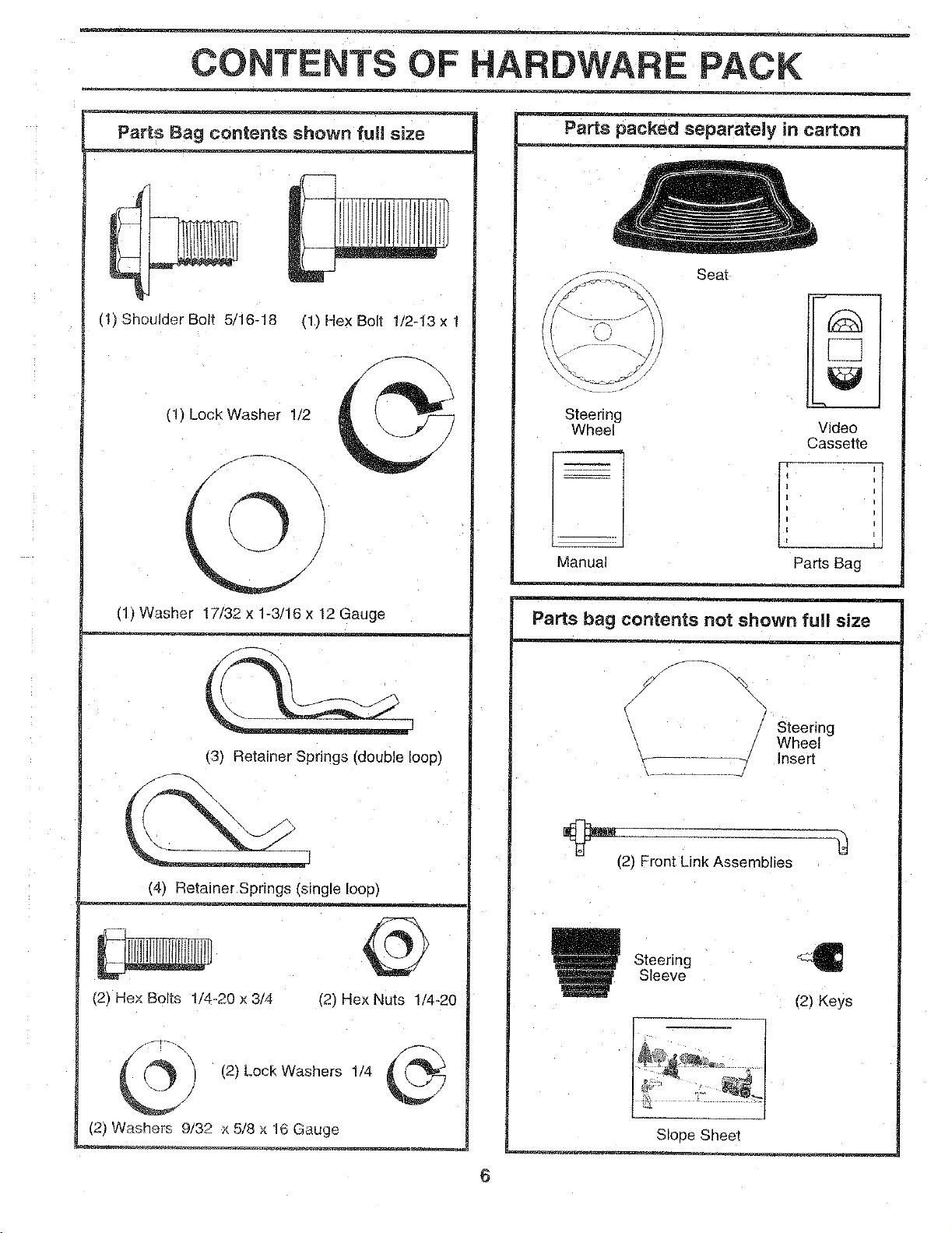
CONTENTS OF PACK
Parts Bag contents shown full size
(t) Shoulder Bolt 5 16-18
(1) HexBolt _/2-13xl
(1) Lock Washer 1/2
4\
/
11)Washer 17/32 x 1-3/16 x 12 Gauge
(31 Retainer Springs (double loop)
(41 Retainer Spnngs (single loop)
(2_ He× Bolts t/4-20 x 3/4 (2) Hex Nuts 1/4-20
(2) Lock Washers 1/4
(2) Washers 9/32 x 5/8 x 16 Gauge
Parts packed separately in carton
o %
Steering
Wheel
Manua,
Seat
Video
Cassette
Parts Bag
Parts bag contents not shown full size
/
/ Steering
Wheel
Insert
(21 Front Link Assemblies
Steering
Sleeve
(2) Keys
Slope Sheet
6
ASSEMBLY
Your new tractor has been assembled at the factory with exception of those parts left unassembled for shipping purposes.
To ensure safe and proper operation of your tractor all parts and hardware you assemble must be tightened securely. Use
the correct tools as necessary to insure proper tightness.
TOOLS REQUIRED FOR ASSEMBLY
A socket wrench set will make assembly easier, Standard
wrench sizes are listed,
(2) 7/16" wrenches Utility knife
(1) 1/2 wrench Tire pressure gauge
(1', 3/4" wrench
When right or left hand is mentioned in this manual, it
means when you are in the operating position (seated
behind the steering wheel),
TO REMOVE TRACTOR FROM CARTON
UNPACK CARTON
Remove all accessible loose parts and parts cartons
from carton (See page 6).
Cut, from top to bottom, along lines on all four corners
of carton, and lay panels flat.
Check for any additional loose parts or cartons and
remove.
BEFORE ROLLING TRACTOR OFF SKID
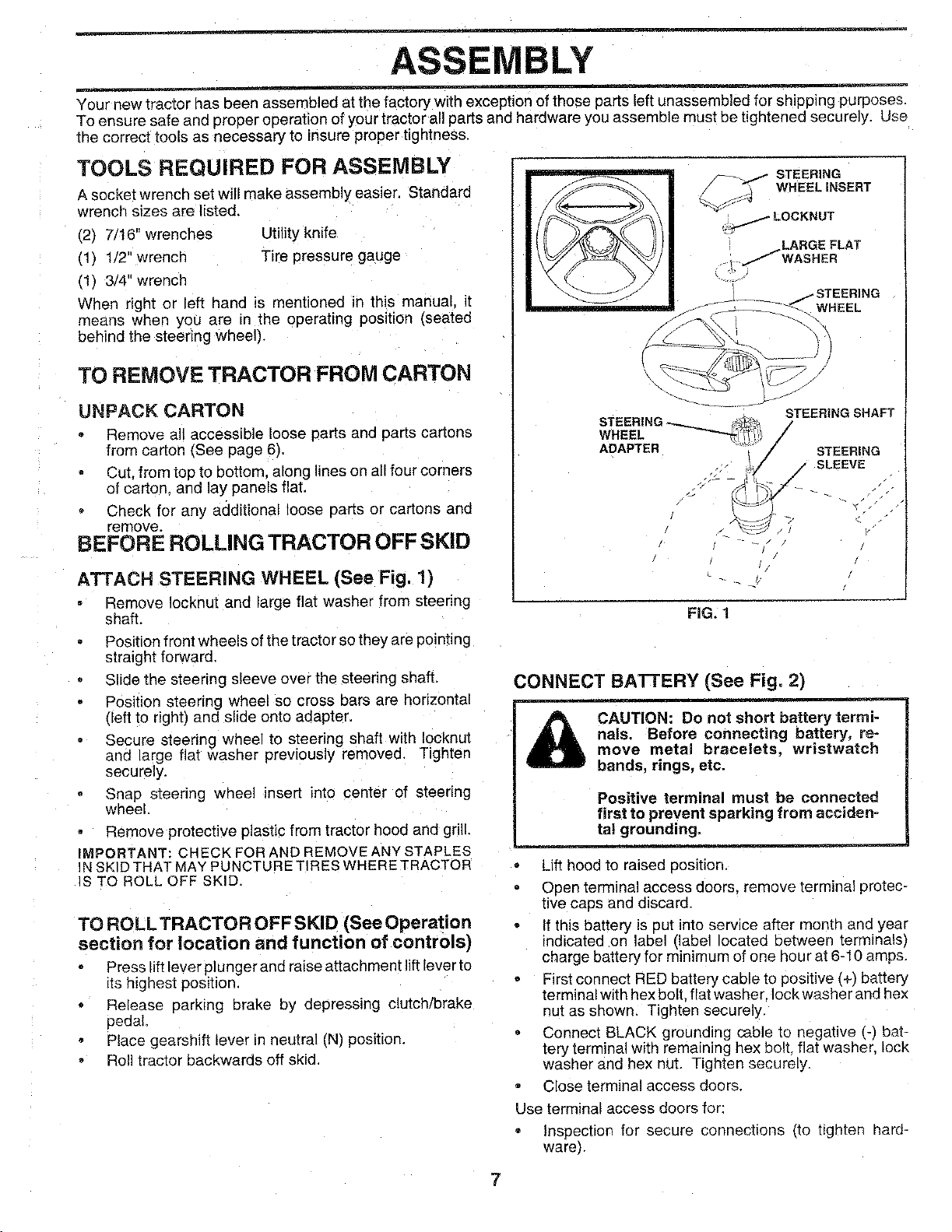
ATTACH STEERING WHEEL (See Fig. 1)
Remove ocknut and large flat washer from steering
shaft.
Position front wheels of the tractor so they are pointing
straight forward,
Slide the steering sleeve over the steering shaft.
Position steering wheel so cross bars are horizontal
deft to right) and slide onto adapter.
Secure steering wheel to steering shaft with IocKnuI
and large flat wasner previously removed. Tighten
securely.
Snap steering wheel insert into center of steering
wheel,
Remove protective plastic from tractor hood and grill,
IMPORTANT: CHECK FOR AND REMOVE ANY STAPLES
IN SKID THAT MAY PUNCTURE TIRES WHERE TRACTOR
IS TO ROLL OFF SKID.
TO ROLLTRACTOR OFF SKID [See Operation
section for location and function of controls)
Press lift lever plunger and raise attachment lift lever to
its highest position
Release parking brake by depressing clutch/brake
pedal
Place gearshift _ever in neutral (N) position.
Roll tractor backwards off skid,
WHEEL
STEERING___
WHEEL
ADAPTER
STEERING SHAFT
/
J STEERING
/ sLeEvE
FIG. 1
CONNECT BATTERY (See Fig. 2)
CAUTION: Do not short battery termi-
nals. Before connecting battery, re-
move metal bracelets, wristwatch
bands, rings, etc.
Positive terminal must be connected
first to prevent sparking from acciden-
ta! grounding.
Lift hood to raised position.
Open terminal access doors, remove terminal protec-
tive caps and discard
If this battery is put into service after month and year
indicated on label (label ocated between terminals)
charge battery for minimum of one hour at 6-10 amps,
First connect RED battery cable to positive (+'Jbattery
terminalwith hex bolt. flat washer Iockwasherand hex
nut as shown. Tighten securely.
Connect BLACK grounding cable to negative _-_bat-
tery terminal with remaining hex bolt. flat washer, ock
washer and hex nut. Tighten securety.
Close terminal access doors.
Use terminal access doors for:
Inspectron for secure connections (to t_gnten hard-
ware}.
7
ASSEMBLY
Inspection for corrosion,
Testing battery,
Jumping (if requiredL
Periodic charging.
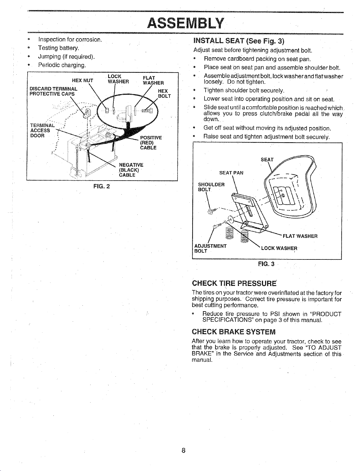
HEX NUT
DISCARD TERMINAL \
PROTECTIVE CAPS
X
LOCK
WASHER
FLAT
WASHER
J HEX
BOLT
TERMINAL
ACCESS
DOOR
POSITIVE
(RED)
CABLE
NEGATIVE
(BLACK)
CABLE
FIG. 2
iNSTALL SEAT (See Fig. 3)
Adjust seat before tightening adjustment boll
Remove cardboard packing on seat pan,
Place seat on seat pan and assemble shoulder bolt.
Assemble adjustment bolt. lockwasher and flat washer
loosely. De not tighten,
Tighten shoulder bolt securely.
Lower seat intooperating position and sit on seat,
Slide seat until acomfortable oosition is reached which
allows you to press clutch/brake pedal all the way
aown.
Get off seat without moving its adjusted position.
• Raise seat and tighten adjustment bolt securely.
SEAT
SEAT PAN
SHOULDER \
BOLT
\
/
ADJUSTMENT "_"
"LOCK WASHER
BOLT
FIG. 3
CHECK TIRE PRESSURE
The tires on your tractor were overinflated at the factory [or
shipping purposes. Correct tire pressure is important for
best cutting performance.
Reduce tire pressure to PSI shown _n "PRODUCT
SPECIFICATIONS" on page 3 of this manual.
CHECK BRAKE SYSTEM
After you learn how to operate your tractor, check to see
that the brake is properly adjusted. See "TO ADJUST
BRAKE" in the Service and Adjustments section of this
manual,
8
ASSEMBLY
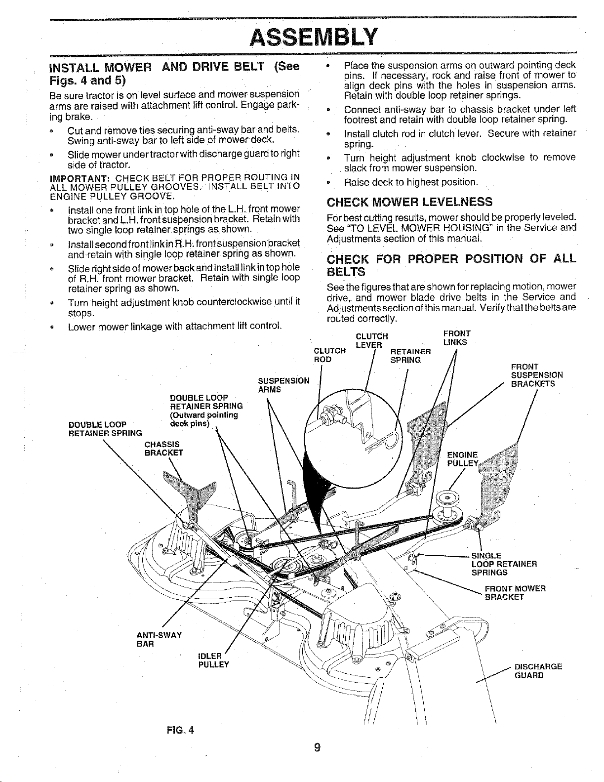
INSTALL MOWER AND DRIVE BELT (See
Figs. 4 and 5)
Be sure tractor is on level surface and mower suseenslon
arms are raised with attachment lift control. Engage park-
ing brake,
Cut and remove ties securing anti-sway bar and belts.
Swing anti-sway bar to left side of mower deck,
Slide mower under tractor with discharge guard to right
side of tractor.
IMPORTANT: CHECK BELT FOR PROPER ROUTING IN
ALL MOWER PULLEY GROOVES. INSTALL BELT INTO
ENGINE PULLEY GROOVE,
Install one front link in top hole of the L.H front mower
bracketandL.H,frontsuspensionbracket, Retain with
two single loop retainer springs as shown.
Install second front link in R.H, front suspension bracket
and retain with single loop retainer spring as shown.
Slide rightside of mower back and install link in top hole
of R.H. front mower bracket. Retain with single loop
retainer spring as shown.
Turn height adjustment knob counterclockwise until it
stoos.
Lower mower linkage with attachment lift control.
DOUBLELOOP
RETAINERSPRING
(Outwardpointing
DOUBLELOOP deck pins)
RETAINERSPRING
\ CHASSIS
BRACKET
\
\
\
\
\
SUSPENSION
ARMS
Place the suspension arms on outward pointing deck
pins. If necessary, rock and raise front of mower to
align deck _ins with the holes in suspension arms,
Retain with double loop retainer springs.
Connect anti-sway bar to chassis bracket under left
footrest and retain with double loop retainer spring.
Install clutch rod in clutch lever. Secure with retainer
spring.
Turn height adjustmem knob clockwise to remove
slack from mower susoension.
Raise deck to highest position.
CHECK MOWER LEVELNESS
For best cutting results, mower should be properly leveled.
See "TO LEVEL MOWER HOUSING" in the Service and
Adjustments section of this manual,
CHECK FOR PROPER POSITION OF ALL
BELTS
See the figures that are shown for replacing motion mower
drive, and mower blade drive belts _ the Service and
Adjustments section ofthis manual. Verify that the belts are
routed correctly.
CLUTCH FRONT
LEVER LINKS
CLUTCH RETAINER
ROD SPRING
FRONT
SUSPENSmON
J BRACKETS
/ /
/
/
/
SINGLE
LOOP RETAINER
SPRINGS
FRONT MOWER
/
ANTI-SWAY
BAR
IDLER i
PULLEY
DISCHARGE
J GUARD
FIG. 4
9
ASSEMBLY
J CHECKLIST
BEFORE YOU OPERATE AND ENJOY YOUR NEW
TRACTOR. WE WISH TOASSURE THAT YOU RECEIVE
THE BEST PERFORMANCE AND SA TISFACTION FROM
THIS QUALITY PRODUCT.
PLEASE REVIEW THE FOLLOWING CHECKLIST:
v" All assembly instructions have oeen completed.
v" No remaining loose parts in carton.
•," Battery is property preparea and charged. (Minimum
1 hour at 6 amps).
,/ Seat is adjusted comfortably and tightened securely.
¢ All tires are properly Enflated. (For shipping purposes
the tires were overinflated at the factory).
J Be sure mower deck IS properly leveled side-to-side/
front-to-rear for best cutting results. (Tires must be
properly inflated for leveling).
,/ Check mower and drive belts. Be sure they are routed
properly around pulleys and inside all belt keepers.
,/ Check wiring. See that all connections are still secure
and wires are properly clamped
WHILE LEARNING HOW TO USE YOUR TRACTOR. PAY
EXTRA A TTENTION TO THE FOLLOWING IMPORTANT
ITEMS:
,/ Engine oil is at proper level.
J Fuel tank is filled with fresh, c_ean, regular unleaded
gasoline.
,/ Become familia" with all controls - their location and
Iunction. Operate them before you start the engine.
J Be sure brake system is in safe operating condition.
10
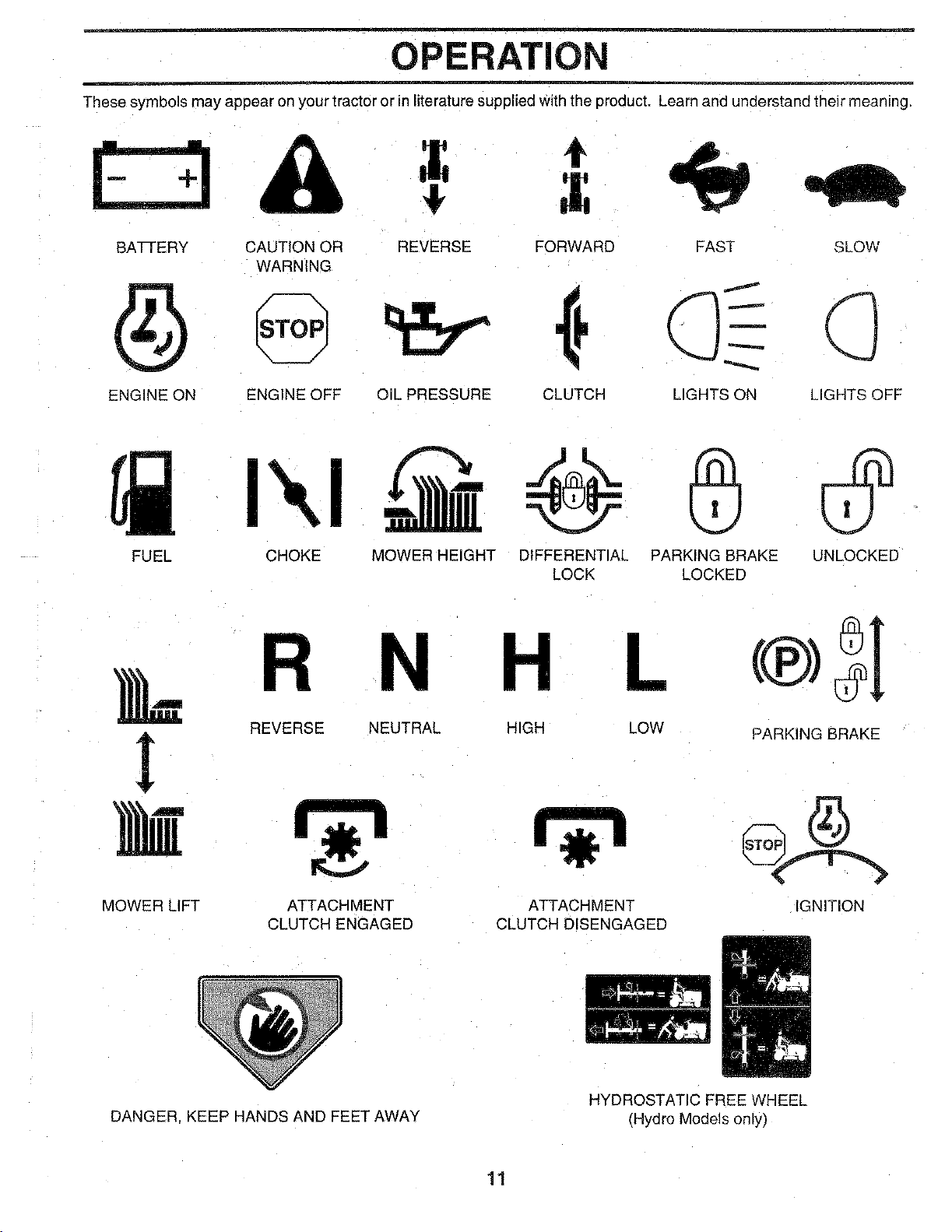
OPERATION
These symbols may appear on your tractor or in literature supplied With the product. Learn and understand their meaning.
Ez3&
BATTERY CAUTION OR REVERSE FORWARD FAST SLOW
WARNING
ENGINE ON ENGINE OFF OIL PRESSURE CLUTCH LIGHTS ON LIGHTS OFF
FUEL
CHOKE MOWER HEIGHT DIFFERENTIAL PARKING BRAKE UNLOCKED
LOCK LOCKED
MOWER LIFT
R N
REVERSE NEUTRAL
ATTACHMENT
CLUTCH ENGAGED
DANGER KEEP HANDS AND FEET AWAY
HIGH LOW PARKING BRAKE
ATTACHMENT
CLUTCH DISENGAGED
IGNITION
HYDROSTATIC FREEWHEEL
(Hydro Modelsory)
11
OPERATION
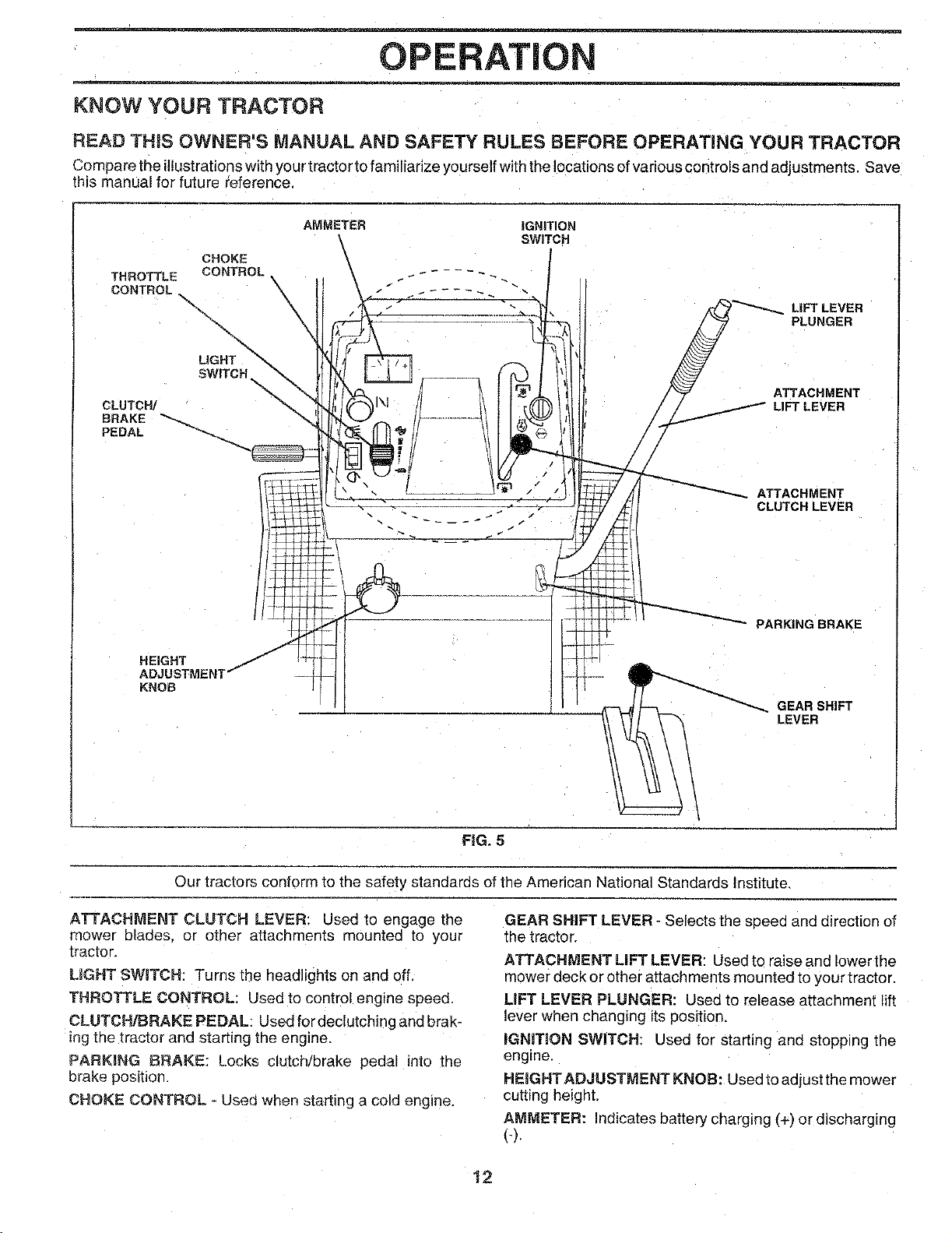
KNOW YOUR TRACTOR
READ THiS OWNER'S MANUAL AND SAFETY RULES BEFORE OPERATING YOUR TRACTOR
Compare the illustrations with your tractor to familiarize yourself with the locations of various controls and adjustments. Save
this manual for future reference.
CHOKE
THROTTLE CONTROL
CONTROL
\
\
\
LIGHT
SWITCH
CLUTCH/
BRAKE
PEDAL
HEIGHT
IGNITION
SWITCH
_A _ LiFT LEVER
LIFT LEVER
RKING BRAKE
KNOB
GEAR SHIFT
LEVER
\
FIG. 5
Our tractors conform to the safety standards of the American National Standards Institute,
ATTACHMENT CLUTCH LEVER: Used to engage the
mower blades, or other attachments mounted to your
tractor.
LIGHT SWITCH: Turns the headlights on and off,
THROTTLE CONTROL: Used to control engine speed,
CLUTCH/BRAKE PEDAL: Used for declutching and brak-
ng the tractor and starting the engine.
PARKING BRAKE: Locks clutch/brake pedal into the
brake position,
CHOKE CONTROL - Usea when starting a cold engine.
GEAR SHIFT LEVER - Selects the speed and direction of
the tractor.
ATTACHMENT LIFT LEVER: Usedtoraiseandlowerthe
mower deck or other attachments mounted to your tractor.
LIFT LEVER PLUNGER: Used to release attachment lift
lever when changing its position.
IGNITION SWITCH: Used for starting and stopping the
engme
HEIGHTADJUSTMENT KNOB: Used to adjust the mower
cutting height,
AMMETER: ndicates battery charging (+) or discharging
(-).
12
OPERATION
_ oreThe
resul_W lie operating YOUr
tract_ViSionsafetymask 1
r the spectacles or standard safety glasses.
HOW TO USE YOUR TRACTOR
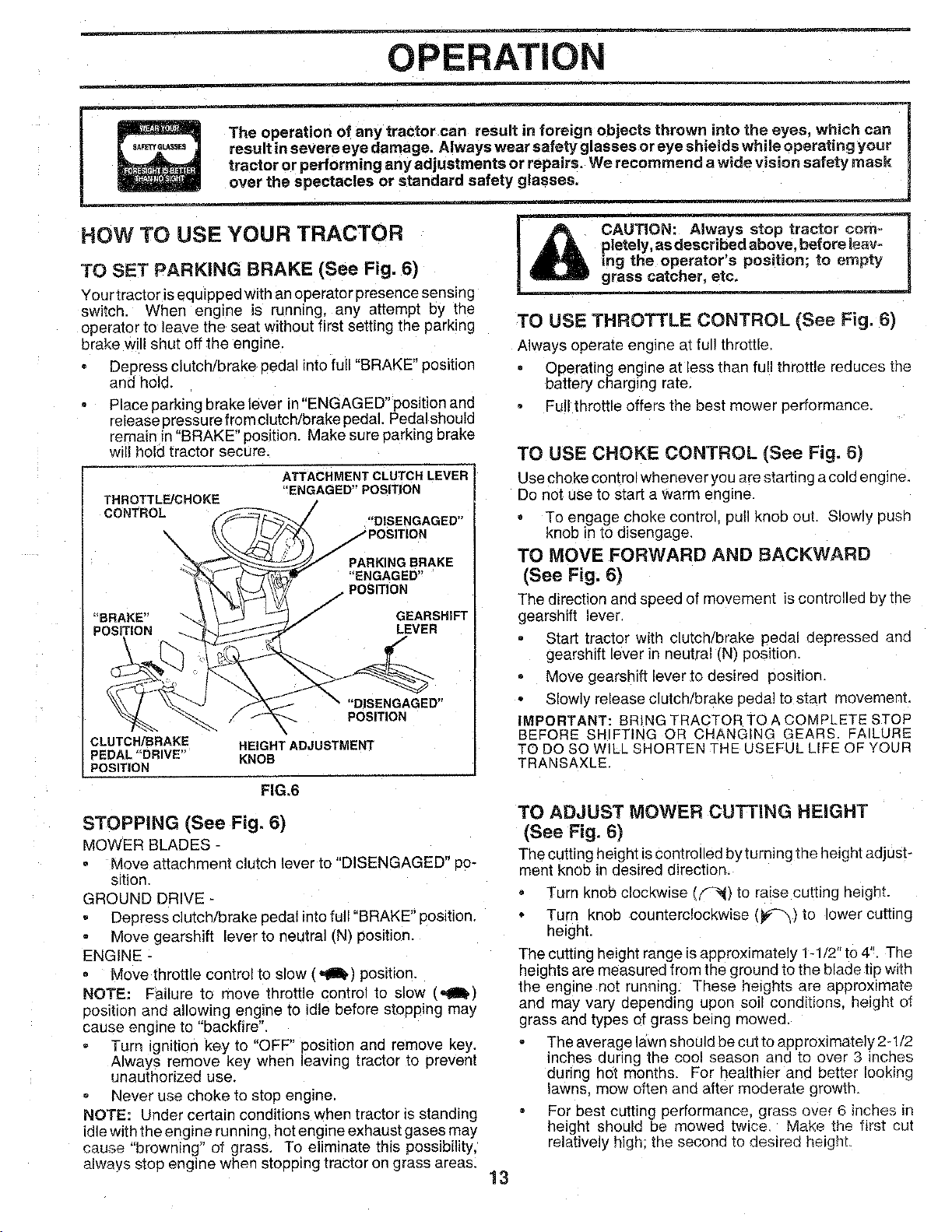
TO SET PARKING BRAKE (See Fig. 6)
Your tractor isequipped with an o0erator presence sensing
switch. When engine is running, any attempt by the
operator to leave the seat without first setting the parking
broke will shut off the engine.
Depress clutch/brake oedal into full "BRAKE" position
and hold.
Place parking brake lever in "ENGAGED" position and
release pressu re from clutch/brake pedal. Pedal should
remain in "BRAKE" position. Make sure parking broke
will hold tractor secure.
THROTTL_CHOKE
CONTROL
ATTACHMENT CLUTCH LEVER
"ENGAGED" POSITION
PARKING BRAKE
"ENGAGED"
j POSITION
GEARSHIFT
LEVER
"DISENGAGED"
POSITION
CLUTCH/BRAKE HEIGHT ADJUSTMENT
_EDAL "DRIVE" KNOB
POSITION
FIG,6
STOPPING (See Fig. 6)
MOWER BLADES -
Move attachment clutch lever to "DISENGAGED" Po-
sition.
GROUND DRIVE -
Depress clutch/brake pedal into full "BRAKE" position.
Move gearshift lever to neutral (N) position.
ENGINE -
Move throttle control to slow (_) position.
NOTE: Failure to move throttle control to slow ("gI,)
eosition and allowing engine to idle before stopping may
cause engine to "backfire".
Turn ignition key to "OFF" position and remove key.
Always remove key when leaving tractor to preven!
unauthorized use.
Never use choke to stop engine.
NOTE: Under certain conditions when tractor is standing
idle with the engine run ning, hot engine exhaust gases may
cause "browning" of grass. To eliminate this possibility,
always stop engine when stopping tractor on grass areas.
A CAUTIO. trao -om--1
,_ _ _dabo.ve ,before lear=
_'s position; to empty
grass catcher, etc,
TO USE THROTTLE CONTROL (See Fig. 6)
Always operate engine at full throttle,
Operating engine at less than full throttle reduces the
battery charging 'ate.
Full throttle offers the best mower performance.
TO USE CHOKE CONTROL (See Fig, 6)
Use choke control wheneveryou are starting a cold engine.
Do not use to start a warm engine
, To engage choke control, putl knob out. Slowly pusn
knob in to disengage.
TO MOVE FORWARD AND BACKWARD
(See Fig. 6)
The direction and speed of movement iscontrolled Dyme
gearshift lever.
Start tractor with clutch/brake pedal depresseo and
gearshift lever in neutral (N) position.
Move gearshift lever to desired position.
Slowly release clutch/brake peoa] to start movemenL
IMPORTANT: BRING TRACTOR TO A COMPLETE STOP
3EFORE SH FTING OR CHANGING GEARS. FAILURE
TO DO SO WILL SHORTEN THE USEFUL LIFE OF YOUR
TRANSAXLE
TO ADJUST MOWER CUTTING HEIGHT
(See Fig. 6)
The cutting height iscontrolled by turning the height adjust-
menl knob in desired direction.
, Turn knob clockwise (_l) to raise cutting height.
Turn knob counterclockwise (_#_) to lower cutting
height.
The cutting height range isapproximately 1-1/2" to 4". The
heights are measured from the ground to the blade tip with
the engine not running. These heights are approximate
and may vary depending upon soil conditions, height of
grass and types of grass being mowed.
The average lawn should be cut to approximately 2-1/2
inches during the cool season and to over 3 inches
during hot months. For healthier and better looking
lawns, mow often and after moderate growth
For best cutting performance, gross over _ inches in
height should De mowed twice Make the first cut
relatively high; the second to desired height.
13
OPERATION
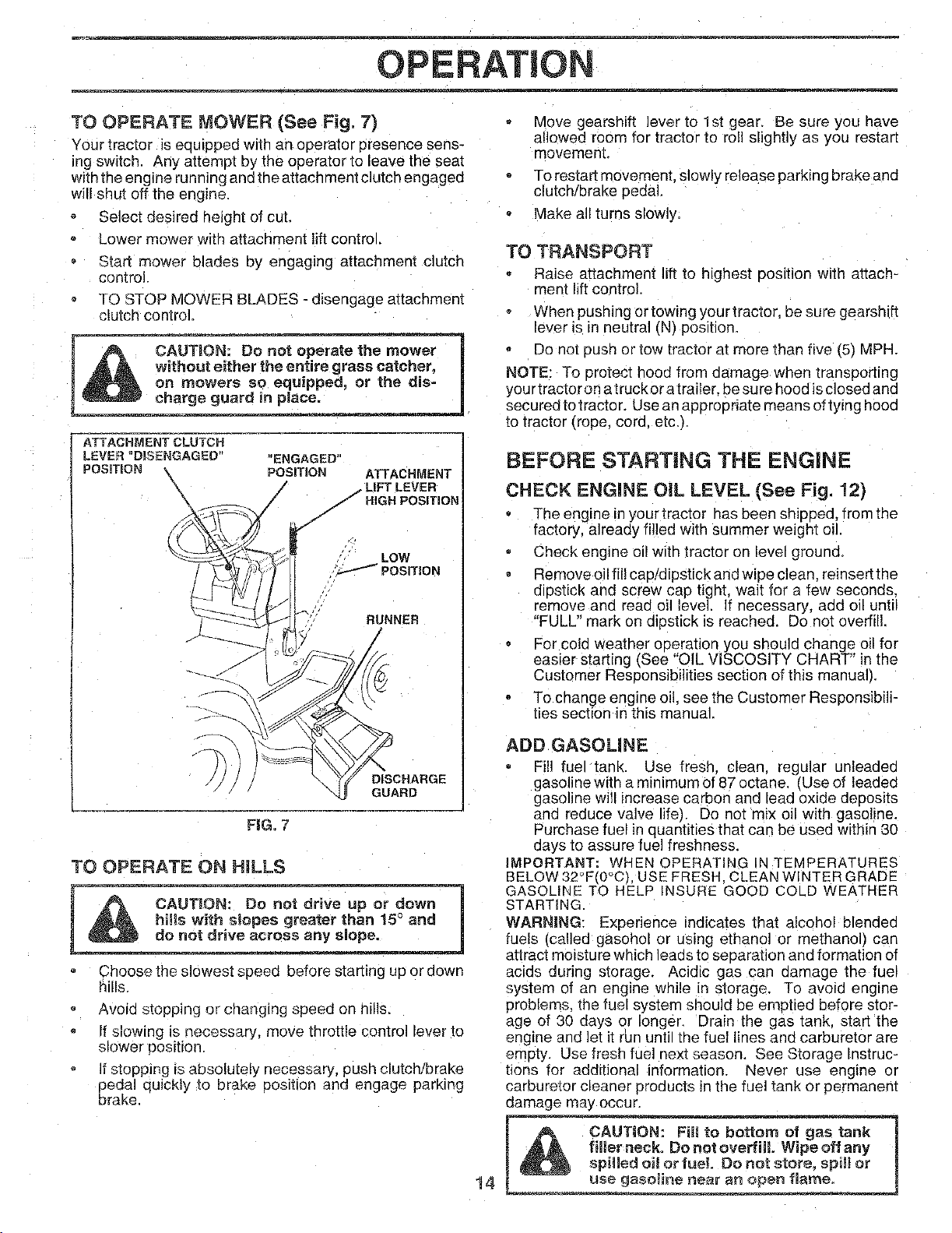
TO OPERATE MOWER (See Fig. 7)
Your tractor isequipped with an operator presence sens-
ing switch. Any attempt by the operator to leave the seat
with the engine running end the attach ment clutch engagee
will shut off the engine.
Select desired height of cut.
Lower mower with attachment liftcontrol.
Stad mower blades by engaging attachment clutch
control.
TO STOP MOWER BLADES - disengage attachment
clutch control.
_ot operate the rno_ -
_ _ _ en_re gtass cateher,
_ on mowers so equipped, or the dis-
A'[ TACHMENT CLUTCH
LEVER "DISENGAGEO" "ENGAGED"
POSITION \ POSITION ATTACHMENT
oLIFT LEVER
\ / //.IaN POSmOH
LOW
_,/POSITION
RUNNER
/
FIG. 7
DISCHARGE
GUARD
TO OPERATE ON HILLS
Choose the slowest speea before starting up or down
hills.
Avoid stopping or changing speed on hills.
If slowing ]s necessary, move throttle control lever io
slower oosition.
It stoppJng is absolutely necessary, push clutch!brake
pedal quickly to brake 3ositior and engage parking
brake
Move gearshift lever to 1st gear, Be sure you have
allowed room for tractor to roll slightly as you restart
movement.
To restart movement, slowly release parking brake and
clutch/brake pedal.
Make all turns slowly.
TO TRANSPORT
Raise attachment lift to highest Position with attach-
ment lift control.
When pushing or towing your tractor, ue sure gearshift
lever is in neutral (N) position.
Do not push or tow tractor at more than five I5t MPH.
NOTE: To orotect hood from damage when transporting
your tractoron a trucker atraiter, be sure hood isclosed and
secured to tractor. Use an appropriate means of tying hood
to tractor (rope, cord. etc.t.
BEFORE STARTING THE ENGINE
CHECK ENGINE OiL LEVEL (See Fig. !2)
The engine in your tractor has been shipped, from the
factory, already filled with summer weight oil.
Check engine oil with tractor on level grouns
Remove oil fil! cap/dipstick and wipe clean, reinsert the
diostick and screw cap tight, wait for a few seconds.
remove and read oil level, if necessary, add oil until
"FULL" mark on dipstick is reached. Do not overfill.
For cold weather operation you should change oil for
easier starting _See "OIL VISCOSITY CHART" in the
Customer Responsibilities section of this manual_.
To change engine oil: see the Customer Responsibili-
ties section in this manual
14
ADD GASOUNE
Fi!! fuel tank. Use fresh, clean, regular unleaded
gasoline with a minimum of 87 octane, rUse of leaded
gasoline will increase carbon and lead oxide deposits
and reduce valve life7 Do not mix o_1with gasoline.
Purchase fuel in quantities that can be used within 30
days to assure fuel freshness.
IMPORTANT: WHEN OPERATING IN TEMPERATURES
BELOW32°F(0°C) USE FRESH. CLEAN WINTER GRADE
GASOLINE TO HELP INSURE GOOD COLD WEATHER
STARTING.
WARNING: Experience indicates that alcohol blended
Iuels (called gasohol or us=ng ethanol or methanol] can
attract moisture which leads to seuaration and formation of
acids during storage. Acidic gas can oamage the fuel
system of an engine while in storage. To avoid engine
problems, the fuel system should be emptied before stor-
age of 30 days or longer. Drain the gas tank. start the
eneEneand let it run unt the fuel lines and carburetor are
empty. Use fresh fuel next season. See Storage Instruc-
tions for additional information, Never use engine or
carburetor cleaner products in the fuel tank or permanent
damage may occur.
I ,_ filler neck. Do not overfimLWipe off any
t sp,leaoil o ot spillor
use gasoline near an open flame.
OPERATION
TO START ENGINE (See Fig. 7)
When starting engine for the first time or if engine has run
out of fuel. it will take extra cranking time to move fuel from
the tank to the engine.
Depress clutch/brake pedal and set parking brake.
Place gearshift lever in neutral (N) position.
k,love attachment clutch to "DISENGAGED" position.
Pull choke control out to choke (l\) position for cold
engine start. For warm eng ne start do not use choke
control.
Move throttle control to midway between fast (._) and
slow I'D*) positions,
rnsert key into ignition and turn keyclockwise to"START"
position and release key as soon as engine starts. Do
not run starter continuously for more than fifteen
seconds per minute, if 'engine does not start after
several attempts, move throttle control to fast (._)
position, wait a few minutes and try again.
When engine starts, slowly push choke control in.
Move throttle control to fast (_,) position.
Allow engine to warm up for a few minutes before
engaging drive or attachments,
NOTE: If at a high altitude (above 3000 feet) or in cold
temperatures (below 32°F), the carburetor fuel mixture
may need to be adjusted for best engine performance. See
"TO ADJUST CARBURETOR" in the Service and Adjust-
ments section of this manual,
MOWING TIPS
= Tire chains cannot be used when the mower housing is
attached to tractor.
Mower should be properly leveled for best mowing
performance. See "TO LEVEL MOWER HOUSING" ir
the Service and Adjustments section of this manual.
= Use the runner on the right hand side of mower as a
guide. The blade cuts aooroximately an inch outside
the runner (See Fig. 7).
• The left hand side of mower should be used for trim-
ming.
Drive so that clippings are dischargee onto the area
that has been cut. Have the cut area to the right of the
tractor. This will result in a more even distribution of
clippings and more uniform cutting,
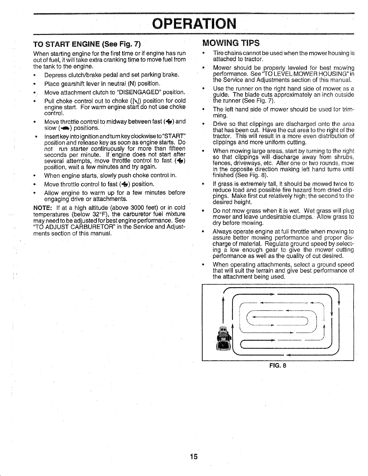
When mowing large areas, start by turning to the right
so that clippings will discharge away from shrubs,
fences, driveways, etc, After one or two rounds mow
in the opposite direction making left hand turns until
finished ISee Fig, 8).
If grass is extremely tall. it should be mowea twice to
reduce load and possible fire hazard from dried clio-
pings, Make first cut relatively high: the second to the
desired height.
• Do not mow grass when it is wet, Wet c "ass will plug
mower and leave undesirable clumps. Allow grass to
ory before mowing.
• Always operate engine at full throttle when mowing to
assure better mowing performance and proper dis-
charge of material. Regulate ground speed by select-
Ing a low enough gear to give the mower cutting
pertormance as well as the quality of cut desired.
When operating attachments, select a ground speed
that will suit the terrain and give best performance ol
the attachment being used.
f
t
J
%.
m
FIG. 8
15
CUSTOMER ;IBIL TIES
I - Change more often when operanng under a heavy moaoor #nn_gh ambient temDera_ures.
2 - _erstce m _re often when operating in dirty or dusty conditions
3 - li _]l ooed with oil f_lter change oil every 50 hour._
a=. Rest_c_ blade_ rflore often wh_ mowing in sanay SOil,
5 - If equipped with adjustable system
6 - Not reauired if e_UIDDe(3W_tl malRtensnce4ree battery
7 - Tighten front axle [3vet Dolt to 35 ft.-Ibs, rnax_num
DOnot ovett_gn[en
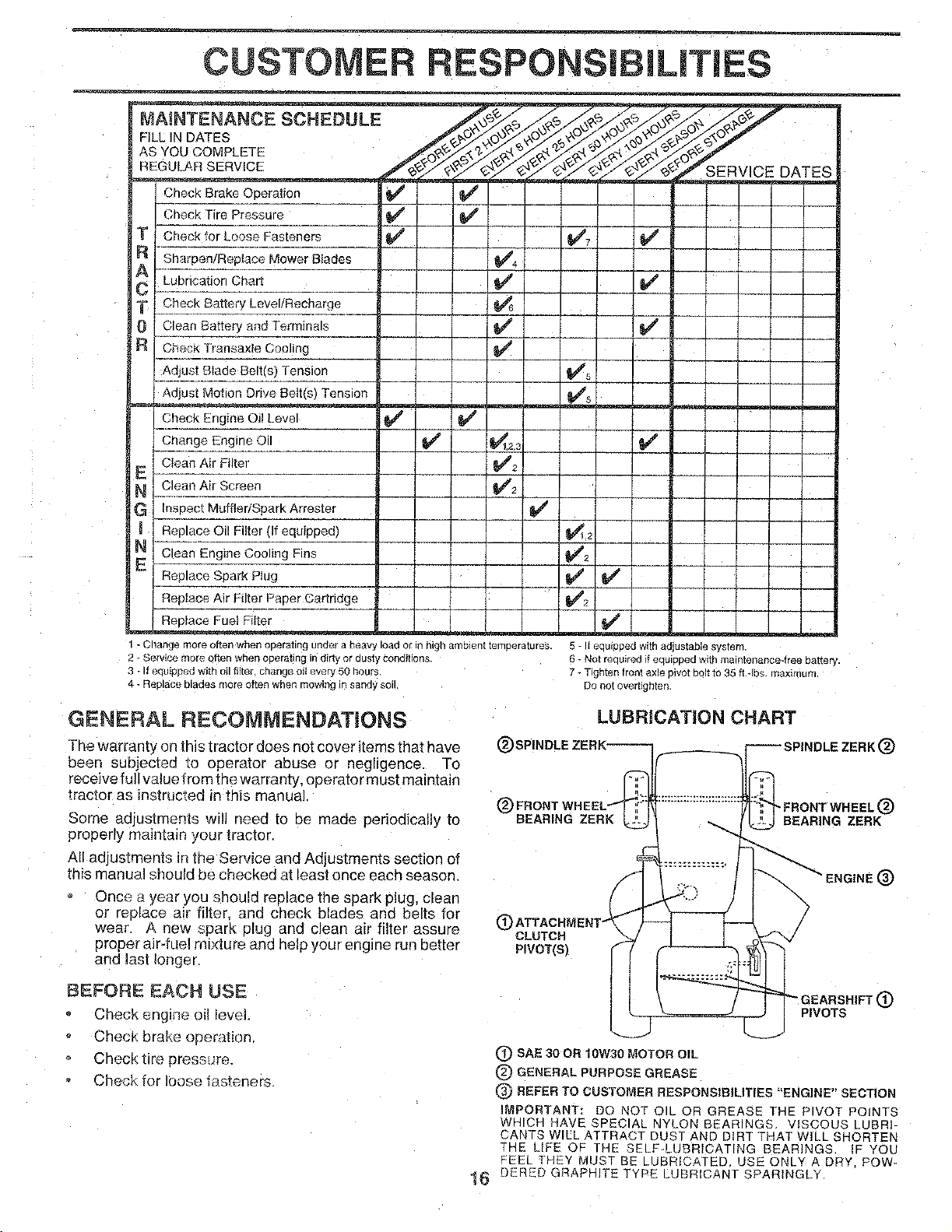
GENERAL RECOMMENDATIONS
The warrantv on this tractor does not cover items that have
been subjected ;o operator abuse or negligence. To
receive full value from the warranty, operator must maintain
tractor as instructed in this manual.
Some adjustments will need to be made periodically to
properly maintain jour tractor.
All aujustments in the SeP4ce and Adjustments section of
this manual should be checked at least once each season
LUBRiCATiON CHART
(_)SPINDLE ZERK---_ _ SPINDLE ZERK _)
Once a year you should replace the soark plug, clean
or replace air filter and check blades and belts for C
wear A new spark plug and clean air filter assure CLUTCH
proper air-fuel mixture and help your engine run better PIVOT(S)
aria last longer
BEFORE EACH USE
Check engine oil level
Check brake operation
Check tire press_re.
Check for loose fasteners.
PIVOTS
®
(_ SAE 30 OR lOW30 MOTOR OIL
(_ GENERAL PURPOSE GREASE
REFER TO CUSTOMER RESPONSIBILITIES "ENGINE" SECTION
IMPORTANT: DO NOT OIL OR GREASE THE PIVOT POINTS
WHICH HAVE SPECIAL NYLON BEARINGS VISCOUS LUBRI-
CANTS WILL ATTRACT DUST AND DIRT THAT WILL SHORTEN
THE LIFE OF THE SELF-LUBRICATING BEAR]ik3S. _ YOU
FEEL THEY MUST BE LUBRICATED, USE ONLY A DRY, Few=
1_ DERBD GRAPHITE TYPE LUBRICANT SPARINGLY.
CUSTOMER RESPONSIBILITIES
TRACTOR
Always observe safety rules when performing any mainte-
nance.
BRAKE OPERATION
• f tractor requires more than six (6) feet stopping distance
at h_ghspeed in highest gear, then brake must be adjustee
(See "TO ADJUST BRAKE" in the Service and Adjust-
'neets section of this manual).
TIRES
Maintain proper air pressure in all tires (See "PROD-
UCT SPECIFICATIONS" on page 3 of this manual).
Keep tires free of gasoline, oil. or insect control chemt-
cals which can harm rubber.
Avoid stumps, stones, deep ruts. sharp objects and
other hazards that may cause tire damage,
BLADE CARE
For best results mower blades must be kept sharp. Re-
place bent or damaged blades.
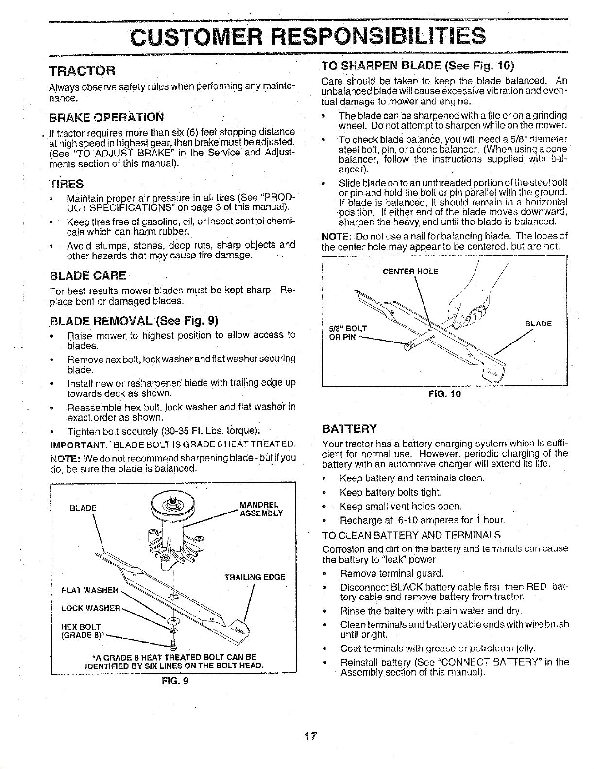
BLADE REMOVAL (See Fig. 9)
Raise mower to highest position to allow access to
blades.
Remove hex bolt, Iockwasher and flat washer securing
blade.
Install new or resharpened blade with trailin§ edge up
towards deck as shown,
Reassemble hex bolt. lock washer and flat washer in
exact order as shown.
Tighten bolt securely (30-35 Ft. Lbs. torque).
IMPORTANT: 3LADE BOLTISGRADE8HEATTREATED.
NOTE: We do not recommend sharpening blade -but ifyou
do. be sure the blade isbalancee
BLADE
MANDREL
/ ASSEMBLY
TRAILING EDGE
HEX BOLT
*A GRADE 8 HEAT TREATED BOLT CAN BE
IDENTIFIED BY SIX LINES ON THE BOLT HEAD,
FIG. 9
TO SHARPEN BLADE (See Fig. 10)
Care should De taken to keep the blade balanced. An
unbalanced blade will cause excesswe vibration and even -
tuat damage to mower and engine,
• The blade can be sharpened with a file or on a grinding
wheel. Do not attempt to sharpen while on the mower.
To check blade balance, youwill needah/8 diameter
steel bolt, pin. or a cone balancer, (When using a cone
balancer, follow the nstructions supplied with bar
ancer).
Slide blade onto an unthreadee portion of the steel bolt
or pin and hold the bolt or pin parallel with the ground.
If blade is balanced, it should rematn in a horizontal
position. If either end of the blade moves downward.
sharpen the heavy end until the blade is balanced.
NOTE: Do not use a nail for balancing blade. The lobes of
the center hole may appear to be centered, but are not.
CENTER HOLE
BLADE
5/8" BOLT
OR PiN /
FIG. 10
BATTERY
Your tractor has a battery chargtng system which is suffi-
cient for normal use. However. periodic charging of the
battery with an automotive charge" will extend its life.
Keep battery and terminals clean.
Keep battery bolts tight.
Keep small vent holes open.
Recharge at 6-10 amperes for 1 hour.
TO CLEAN BATTERY AND TERMINALS
Corrosion and dirt on the battery ane terminals can cause
the battery to "leak" power.
• Remove terminal guard.
Disconnect BLACK battery cable first then RED bat-
tery cable and remove battery from tractor.
° Rinse the battery with plain water and dry.
Clean terminals and battery cable ends with wire brush
until bright.
Coat terminals with grease or petroleum jelly.
Reinstall battery (See "CONNECT BATTERY" _nthe
Assembly section of this manualL
t7
CUSTOM LINES
V_BELTS
Check V-belts for deterioration and wear after 100 hours of
operation and replace if necessary, The belts are not
adjustable. Replace belts if they begin to slip from wear.
TRANSAXLE COOUNG
KeeD transaxle free from build-urJ of dirt and chaff which
can restrict cooling.
ENGINE
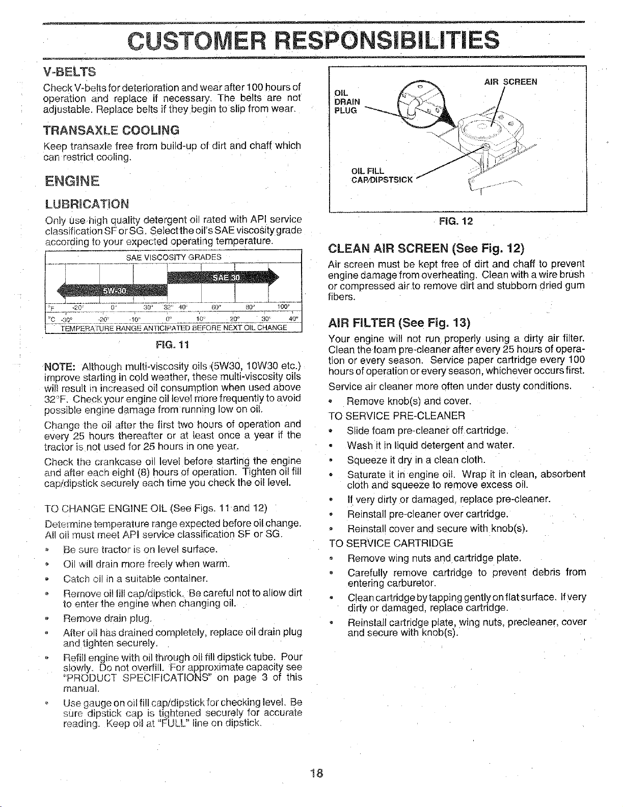
LUBRICAT_ON
Only use h_ghquality detergent oi! rated with API service
c_assification SF or SG, Select the oirs SAE viscosity graae
according to your expected oeeratlng temperature,
SAE VISCOSITY GRADES
"F -20 -- 30' 32 40 60' 80 100
_C -30_ _ _-2_ _ __:10 O' .___ _u ..... 20 ° __ 30' 40_
fFMPERATURE RANGE ANTICIPATED BEFORE NEXT O _ CHANGE
FIG, 11
NOTE: Although multi-viscosity oils (5W30. 10W30 etc,_
improve starting in cold weather, these muLtFviscosity oils
will result in increased oil consumotion when used above
32°F. Check your engine oil level more frequently toavoid
possible engine damage from running low on oil,
Change the oil after the first two hours of operation and
every 25 hours thereafter or at least once a year if the
tractor is not used for 25 hours in one year,
Check the crankcase oi level before starting the engine
and after each eight (8) hours of operation. Tighten oil fill
cap/dipstick securely each time you check the oil level.
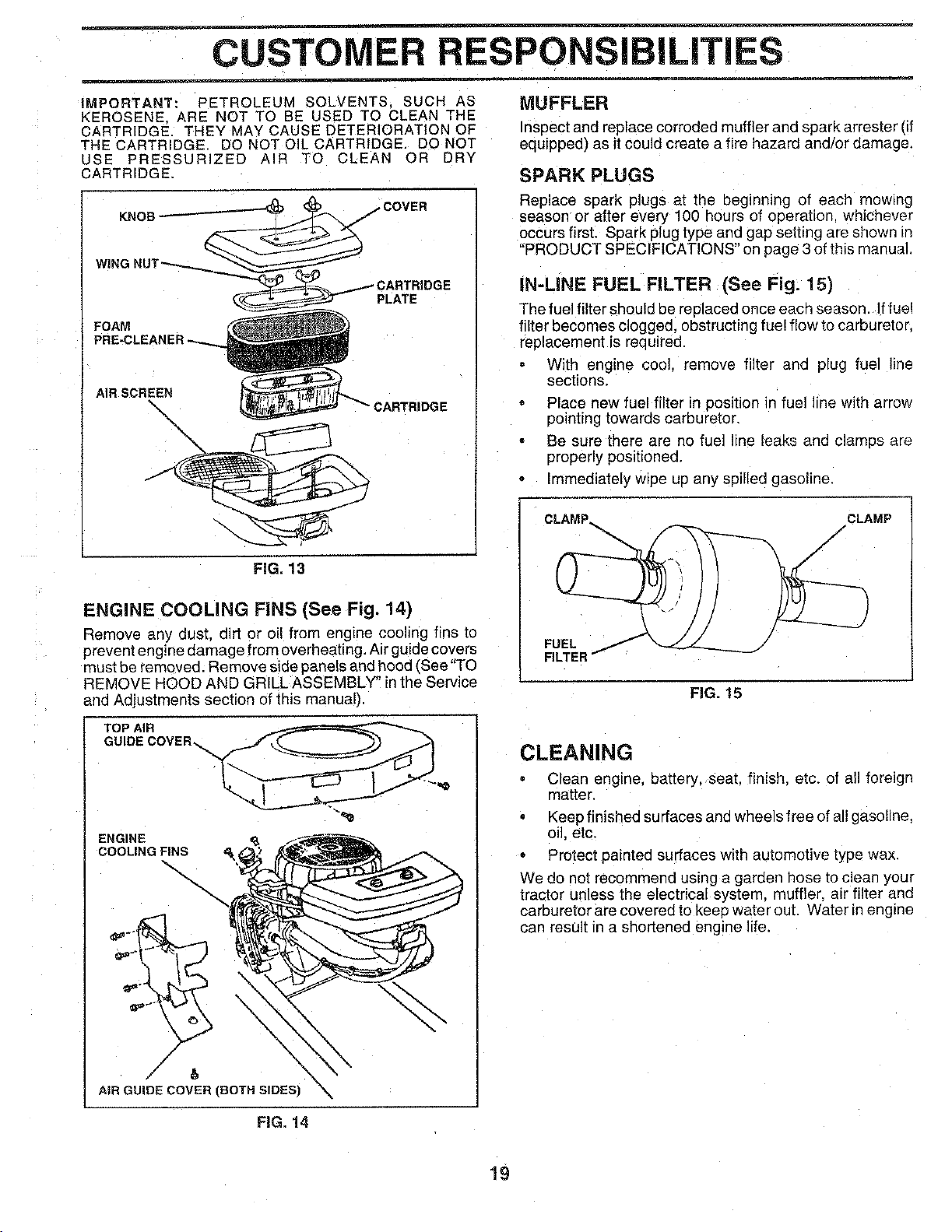
TO CHANGE ENGINE OIL (See Figs. 11 and 12)
Determine temperature range exeectea before oil change.
All Oll squst meet APt service classification SF or SG
Be sure tractor is on level surface,
Oil will drain more fi-eely when warm,
Catch c in a suitable container.
Remove oil filI cap/alpstick. Be careful not to allow dirt
to enter the engine when changing oil
Remove drain plug.
After oil has drained completely, replace oi drain p_ug
and tighten securely,
Refill engine with el! through oil fi!l dipstick tube. Pour
slowty. Do not overtilL For approximate capacity see
"PRODUCT SPECIFICATIONS" on page 3 of (hB
manual
Use gauge on oil fill cap/diostlck for checking level Be
:_ure diestick cae ts tightened securely for accurate
readm:j. Keee oil _;.t FULL hne on aJsstick
%'N /
OIL FILL ._" _:_"
OAPA)IPSTSICK/"
AIR SCREEN
FEG.12
CLEAN AIR SCREEN (See Fig. 12)
Air screen must be kept free of dirt and chaff to prevent
engine aamage from overheating. Clean with a wire brush
or compressed air to remove dirt and stubborn dried gum
fibers.
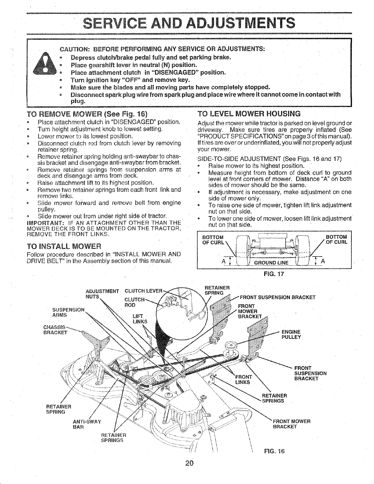
AiR FILTER (See Fig, 13)
Your engine wil! not run properly using a dirty air filter.
Clean the foam pro-cleaner after every 25 hours of opera-
tion or every season. Service par)or cartridge every 100
hours of operation or every season, whichever occurs first.
Service air cleaner more often under ousty conditions.
Remove knobts; and cover.
TQ SERVICE PRE-CLEANER
Slide foam pre-cleaner off cartrioge.
Wash it in lieuid detergent and water.
Squeeze it dry m a clean cloth,
Saturate it in engine oil. Wrap it in clean, absorbent
cloth and squeeze to remove excess oil.
If very drrty or damaged, replace pre-cleaner.
Reinstall ore-cleaner over cartriqge.
Reinstall cover and secure with knob(s).
TO SERVICE CARTRIDGE
Remove wing nuts and cartridge plate.
Carefully remove cartridge to prevent oebris from
entering carburetor.
Clean cartridge bytapping gently on flat surface. Ifvery
dirty or damaged, replace cartridge.
Reinstall cartridge plate, wing nuts. precleaner, cover
and secure with knob(s).
18
CUSTOMER RESPONSIBILITIES
IMPORTANT: PETROLEUM SOLVENTS SUCH AS
KEROSENE. ARE NOT TO BE USED TO CLEAN THE
CARTRIDGE, THEY MAY CAUSE DETERIORATION OF
THE CARTRIDGE. DO NOT OIL CARTRIDGE. DO NOT
USE PRESSURIZED AIR TO CLEAN OR DRY
CARTRIDGE.
PLATE
KNOB
FIG. 13
FOAM
PRE-CLEAN
:OVER
AiR SCREEN
\
\
MUFFLER
inspect and replace corroded muffler and spark arrester (if
equipped) as it could create a fire hazard and/or damage.
SPARK PLUGS
Replace spark plugs at the eeginnmg of each mow_ng
season or after every 100 hours of operation whichever
occurs first. Spark plug type and gap setting are shown _n
"PRODUCT SPECIFICATIONS" on page 3 of this manual
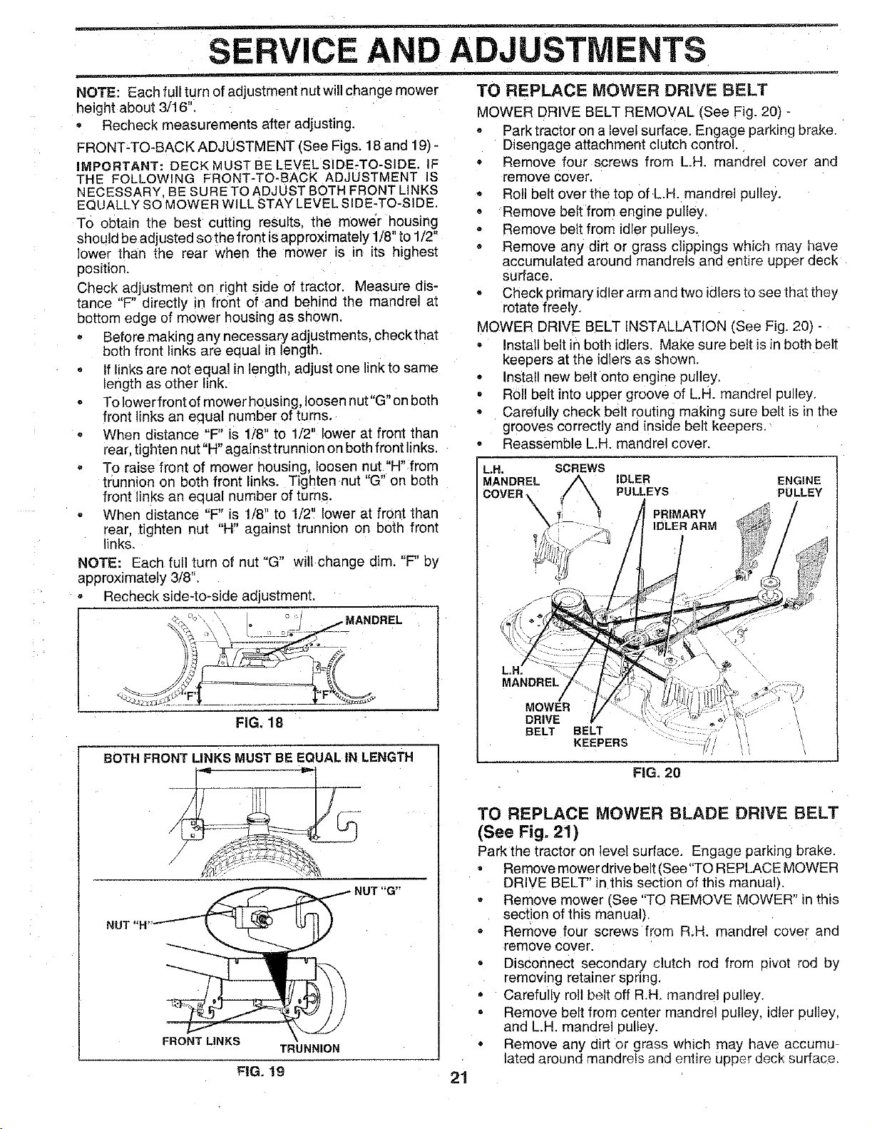
IN-LINE FUEL FILTER (See Fig. 15)
The fuel filter should be replaced once each season. If fue!
filter becomes clogged, obstructing fuel flow to carburetor.
replacement is required.
With engine cool, remove filter ana plug fuel line
sections.
Place new fuel filter in position in fuel line with arrow
pointing towards carburetor.
Be sure there are no fuel line leaks and clamps are
properly positioned.
Immediately wipe ue any spilled gasoline.
CLAMP... CLAMP
/
/
ENGINE COOLING FINS (See Fig. 14)
Remove any dust, dirt or oi! from engine cooling fins to
prevent engine damage from overheating. Air guide covers
must be removed. Remove side panels and hood {See "TO
REMOVE HOOD AND GRILL ASSEMBLY" in the Service
and Adjustments section of this manual).
FUEL
FILTER
FIG. 15
)
TOP AIR
GUIDE COVER.
ENGINE _& f_
COOLING FINS
2.
/,
AIRGUIDECOVER(BOTHSIDES)
CLEANING
Clean engEne, battery, seat. finish, etc. of all foreign
matter.
Keep finished surfaces and wheels free of all gasoline,
oil, etc.
• Protect painted surfaces with automotive type wax.
We do not recommend using a garden hose to clean your
tractor unless the electrical system, muffler, air filter and
carburetor are covered to keep water out. Water in engine
can result in a shortened engine life.
FiG. 14
19
ERVlCE ADJUSTMENTS
CAUTION: BEFORE PERFORMING ANY SERVICE OR ADJUSTMENTS:
! Depress clutch/brake pedal futly and set parking brake.
Place gearshift lever in neutral IN) position.
Place attachment clutch in "DISENGAGED" position.
Turn ignition key "OFF" and remove key.
* Make sure the btsdes and aH moving parts have completely stopped,
Disconnect spark plug wire from spark plug and place wire where it cannot come in contact with
plug,
TO REMOVE MOWER (See Fig. 16)
Place attachment clutch in "DISENGAGED" position.
Turn height adjustment knob to lowest setting.
Lower mower to ts lowest position.
Disconnect clutch rod from clutch lever by removing
retainer spring,
Remove retainer spnng holding antt-swaybar to chas-
sis bracket and disengage anti-swaybar from bracket.
Remove retainer springs frorr suspension arms at
deck and disengage arms from decK.
Raise attachment lift to its highest position.
Remove two retainer springs from each front link and
remove links.
Slide mower forward and remove belt from engine
pulley.
Slide mower oul from under right side of tractor.
IMPORTANT: FAIk ATTACHMENT OTHER THAN THE
MOWER DECK 15TO BE MOUNTED ON THE TRACTOR.
REMOVE THE FRONT LINKS.
TO iNSTALL MOWER
Follow eroceaure described in "INSTALL MOWER AND
DRIVE BELT" in the Assembly section of this manual
TO LEVEL MOWER HOUSING
Adjust the mower while tractor is parked on level ground or
driveway. Make sure tires are propeny inflated (See
"PRODUCT SPECIFICATIONS" on page 3 of this manual).
If tires are over or underinflatee, you will not properly adjust
your mower.
SIDE-TO_S_DE ADJUSTMENT ISee Figs. 16 and 17)
Raise mower to its highest position.
Measure height from bottom of deck curl to ground
level at front corners of mower. Distance "A" on both
sides of mower should be the same.
If adjustment ISnecessary, make adjustment on one
side of mower only.
To raise one side of mower, tighten lift link adjustment
nut on that side.
To lower one side of mower, loosen lift link adjustment
nut on that side.
BOTTOM F--_ _ _ BOTTOM
o, co-
FIG. 17
ADJUSTMENT CLUTCH LEVER_
NUTS
SUSPENSION
ARMS
RETAINER
SPRING
FRONT
ENGINE
PULLEY
/
/
RETAINER
SPRING
£ETAINER
SPRINGS
FRONT
SUSPENSION
X BRACKET
\
RETAINER
FRONT MOWER
BRACKET
FIG, 1B
20
SERVICE AND ADJUSTMENTS
NOTE: Each full turn of adjustment nut will change mower
qeight about 3/16".
, Recheck measurements after adjusting.
FRONT-TO-BACK ADJUSTMENT (See Figs. 18 and 19) -
IMPORTANT: DEC K MUST BE LEVEL SIDE-TO-SIDE. IF
THE FOLLOWING FRONT-TO-BACK ADJUSTMENT S
NECESSARY BE SURE TO ADJUST BOTH FRONT LINKS
EQUALLY SO MOWER WILL STAY LEVEL SIDE-TO-SIDE.
To obtain the best cutting results, the mower housing
should be adjusted so the front isapproximately 1/8"to 1/2"
lower than the rear when the mower is _rl its highest
position.
Check adjustment on right side of tractor. Measure dis-
tance "F" directly in front of and behind the mandrel at
bottom edge of mower housing as shown,
Before making any necessary adjustments check that
both front links are eaual in length.
If links are not equal in length, adjust one link to same
length as other link.
To lowerfront of mower housing, loosen nut"G" on both
front links an equal number of turns.
When distance "F" is 1/8" to 1/2" lower at front than
rear, tighten nut "H" agalnsttrunn]on on both front links.
To raise front of mower housing, loosen nut "H" from
trunnion on both front links. Tighten nut "G" on both
front links an equal number of turns.
• When distance "F" is 1/8" to 1/2" lower at front than
rear. tighten nut "R" against trunnion on both front
links.
NOTE: Each full turn of nut "G" will change dim. "F" by
approximately 3/8".
Recheck side-to-side adjustment.
FIG, 18
BOTH FRONT LINKS MUST BE EQUALIN LENGTH
TO REPLACE MOWER DRIVE BELT
MOWER DRIVE BELT REMOVAL (See Fig. 20) -
Park tractor on a level surface, Engage parking brake.
Disengage attachment clutch control.
Remove four screws from LH. mandrel cover and
remove cover,
Roll belt over the top of L.H. mandrel pulley.
• Remove belt from engine pulley,
Remove belt from idler pulleys.
• Remove any dirt or grass clippings which may have
accumulated around mandrels and entire upper deck
surface.
Check primary idler arm and two idlers to see that they
rotate freely.
MOWER DRIVE BELT INSTALLATION (See Fig. 20) -
Install belt in both idlers. Make sure belt is in both belt
keepers at the idlers as shown,
Install new belt onto engine pulley.
Roll belt into upper groove of L.H. mandrel pulley,
• Carefully check belt routing making sure belt is in the
grooves correctly and inside belt keepers.
Reassemble L.H. mandrel cover.
L.H, SCREWS
MANDREL IDLER
PULLEYS
ENGINE
PULLEY
PRIMARY
IDLER ARM
MANDREL
/
MOWER
DRIVE
BELT BELT
KEEPERS ,%
FIG. 20
TO REPLACE MOWER BLADE DRIVE BELT
(See Fig. 21)
Park the tractor on level surface. Engage parking brake
Remove mower drive belt (See "TO REPLACE MOWER
DRIVE BELT" in this section of this manual).
Remove mower (See "TO REMOVE MOWER" in this
section of this manuab,
Remove four screws from R.H. mandrel cover and
remove cover.
Disconnect secondary clutch rod from Divot rod by
removing retainer spnng,
Carefully roll belt off R,H, mandrel pulley.
• Remove belt from center mandre! pulley, idler pulley,
and L.H, mandrel pulley.
• Remove any dirt or grass which may have accumu-
lated around mandrels and entire upper deck surface.
FRONT LINKS TRUNNION
PIG. 19 21
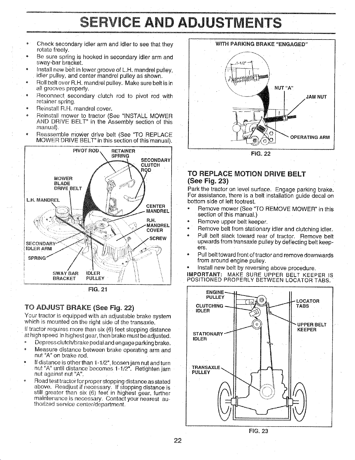
ITS
Check secondary idler arm and idler to see that they
rotate freely.
Be sure sefing is hooked in secongary idler arm ant
sway-bar bracket.
Install new belt in lower groove of L.P mandrel pulley,
idler pulley: and center mandrel pulley as shown.
Roll belt over R.H. mandrel pulley. Make sure belt is ir
all grooves properly,
Reconnect secondary clutch "on to oivot rod with
retainer spnng.
Reinstall R,H, mandrel cover.
ReinstaJ mower to tractor (See "INSTALL MOWER
AND DRIVE BELT" in the Assembly section of this
manuah
Reassemele mower drive belt iSee "TO REPLACE
MOWER DRIVE BELT" in this section of this manual).
PIVOT ROD RETAINER
SPRING
SECONDARY
CLUTCH
ROD
LH, MANDREL
SWAY BAR iDLER
BRACKET PULLEY
RG. 21
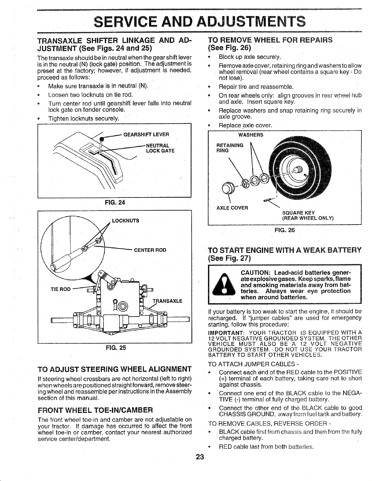
TO ADJUST BRAKE (See Fig, 22)
Your tractor is equipped with an adjustable brake system
which is mounted on :he right side of the transaxle.
If tractor reouJres rnore than s_×(6) feet stopping distance
at _l_ghspeed in higeest gear. then brake must be adjusted.
Depress clutch/brake pedal and engage parking brake.
Measure distance between brake operating arm and
nut "A" on brake rod.
Ifdistancelsotherthan 1-1/2" loosen jam nut andturn
1ul "A" until distance becomes 1-1/2". Retighten jam
nut against nut "A".
Road test tractor for proper stopping distance as stated
above. Readjust if necessary_ If stopping distance is
sti!l greater than six (6_ feet in highest gear further
maintenance is necessary Contact your nearest au-
thorized service cemer/aepartment
WITH PARKING BRAKE "ENGAGED"
/ \
NUT "A"
• _---J_ I/JAM NUT
_ i' OPE AT'°OARMt
FiG. 22
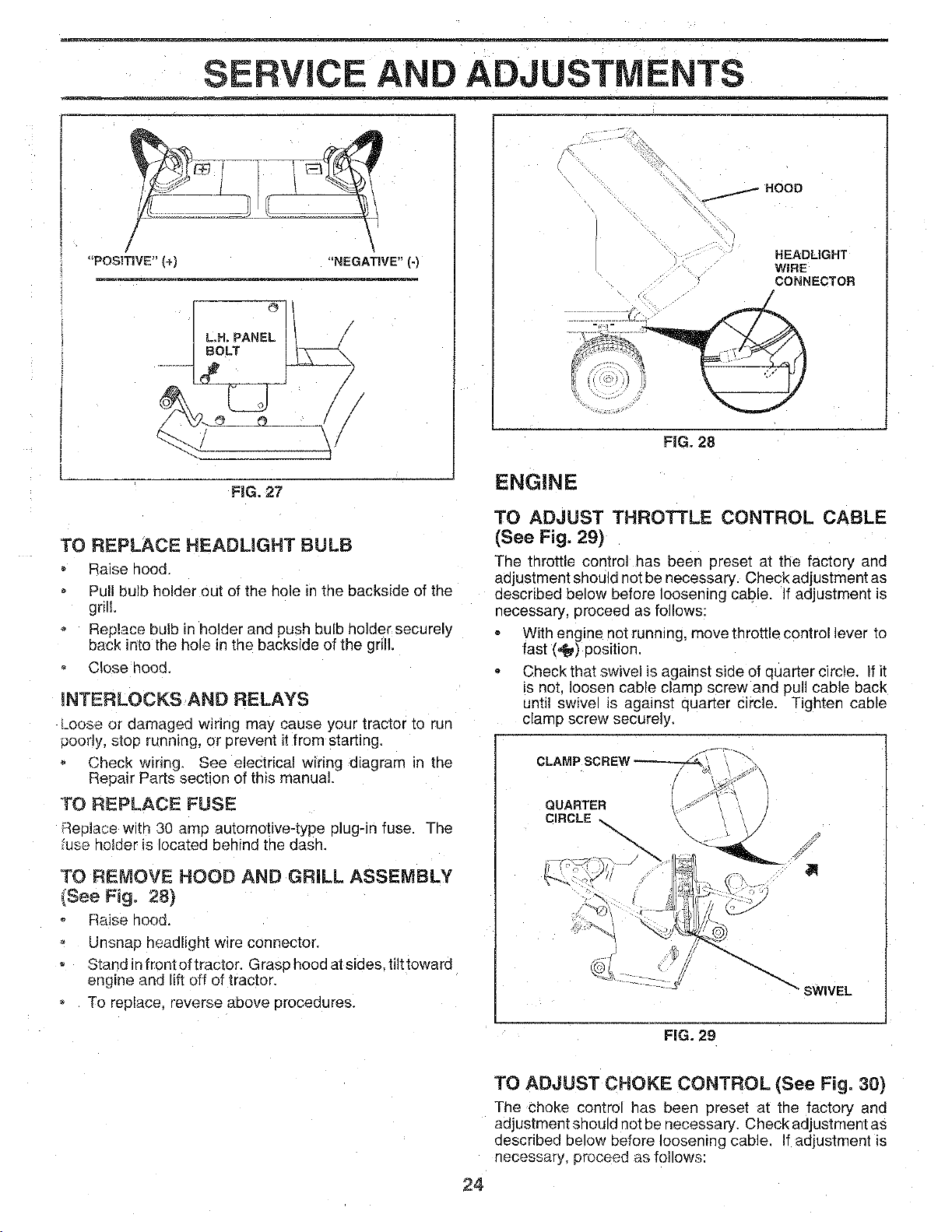
TO REPLACE MOTION DRIVE BELT
(See Fig. 23)
Park the tractor on revel surface. Engage parking brake.
For assistance, there is a belt installation guide decal on
bottom side of left footrest.
Remove mower See "TO REMOVE MOWER" in this
section of this manual.)
Remove upper belt keeuer.
Remove belt from stationary idler and clutching idler.
Pull belt slack toward rear of tractor _emove belt
uewards from transaxle pulley by deflecting belt keep-
ers.
Pull belt toward rront oftractor and remove downwards
from around engine pulley.
Install new oelt by reversing above procedure.
IMPORTANT: MAKE SURE UPPER BEL_ KEEPER IS
POSITIONED PROPERLY BETWEEN LOCATOR TABS.
PULLEY
_LOCATOR
CLUTCRIN( TABS
iDLER
IDLER
KEEPER
PULLEY
22
FIG_ 23
SERVICE AND
TRANSAXLE SHIFTER LINKAGE AND AD-
JUSTMENT (See Figs. 24 and 25)
The transaxle should be in neutral when the gear shift lever
is in the neutral (N) (lock gate) position. The adjustment is
preset at the factory; however, if adjustment is needed.
proceed as follows:
Make sure transaxle is in neutral (N).
Loosen two Iocknuts on tie rod.
Turn center rod until gearshift lever falls into neutral
ock gate on fender console,
• Tighten Iocknuts securely.
r..._.-_GEARSHIFT LEVER
FIG, 24
LOCKNUTS
3ENTER ROD
TIE ROD
TRANSAXLE
FIG. 25
TO ADJUST STEERING WHEEL ALIGNMENT
Ifsteering wheel crossbars are not horizontal (left to right)
when wheels are positioned straight forward, remove steer-
tng wheel and reassemble per instructions inthe Assembly
section of this manua
FRONT WHEEL TOE-IN/CAMBER
The front wheel toe-in and camber are not adjustable o_
your tractor, If damage has occurred to affect the front
wheel toe-in or camber, contact your nearest authorized
service center/department.
ADJUSTMENTS
TO REMOVE WHEEL FOR REPAIRS
(See Fig, 26)
Block up axle securely,
Remove axle cover, retaining ring and washersto allow
wheel removal (rear wheel contains a square key - Do
not lose).
Repair tire and reassemble.
o On rear wheels onJy: align grooves in rear wheel hub
and axle, Insert square Key.
Replace washers and snae retaining nng securely in
axle groove,
Replace axle cover,
WASHERS
RETAINING
RING
\
\
\
AXLE COVER
SQUARE KEY
{REAR WHEEL ONLY)
FIG 26
TO START ENGINE WITH A WEAK BATTERY
See Fig. 27)
CAUTION: Lead-acid batteries gener-
ate explosive gases. Keep sparks, flame
and smoking materials away from bat-
teries. Always wear eye protection
when around batteries.
if your battery is too weak to start the engine, it should be
recharged. If "jumper cables" are used for emergency
starting, follow this Procedure:
IMPORTANT: YOUR TRACTOR S EQUIPPEDWlTH A
12VOLT NEGATIVE GROUNDED SYSTEM. THE OTHER
VEHICLE MUST ALSO BE A !2 VOLT NEGATIVE
GROUNDED SYSTEM. DO NOT USE Y'OURTRACTOR
BATTERY TO START OTHER VEHICLES.
TO ATTACH JUMPER CABLES -
Connect each end of the RED cable to the POSITIVE
(+) terminal of each battery, taking care not to short
against chassis,
Connect one end of the BLACK cable to the NEGA-
TIVE (-) terminal of fully charged battery.
Connect the other end of the BLACK cable to good
CHASSIS GROUNB away from fuel tank and battery.
TO REMOVE CABLES. REVERSE ORDER -
BLACK cable first from chassis and then from the fully
charged battery.
RED cable last from both batteries,
23
SERVICE AND ADJUSTMENTS
/
"POSITIVE" (+) "NEGATIVE" (-)
IL°PANE;!
FiG. 27
_'O REPLACE HEADLIGHT BULB
Raisehood.
Pullbulbholderoutoftheholeinthebacksideofthe
grill.
Replacebulbinholderand push bulbholdersecurely
back intotheholeinthebacksideofthegrill.
C!ose nooq.
_NTERLOCKSAND RELAYS
LOOSeor damaged wiring may cause your tractor to run
uoorly, stop running, or prevent itfrom starting.
Check w_nng, See electrical wiring diagram in the
Repair Parts Section of this manual.
TO REPLACE FUSE
:_eulase with 30 amp automotrve-type plug-in fuse. The
fuse holder is ocated behind the dash.
'FO REMOVE HOOD AND GRILL ASSEMBLY
(See Fig. 28)
Raise hood.
Unsnap headlight wire connector.
Stand in front of tractor. Grasp hood at sides, tilt toward
engine and lift off of tractor.
To replace, reverse above procedures.
_HOOO
HEADLIGHT
WIRE
CONNECTOR
FIG. 28
ENGINE
TO ADJUST THROTTLE CONTROL CABLE
(See Fig. 29)
The throttle control has been preset at the factory and
adjustment should not be necessary. Check adjustment as
described below before loosening cable. If adjustment is
necessary, proceea as follows:
With engine not running, move throttle control lever to
fast (,_) position.
Check that swivel is against side of quarter circle. If it
s not. _oosen cable clamp screw and DUllcable back
until swive is against quar[er circle. Tighten cable
clamp screw securely.
QUARTER
CIRCLE-_
" SWIVEL
FIG. 29
24
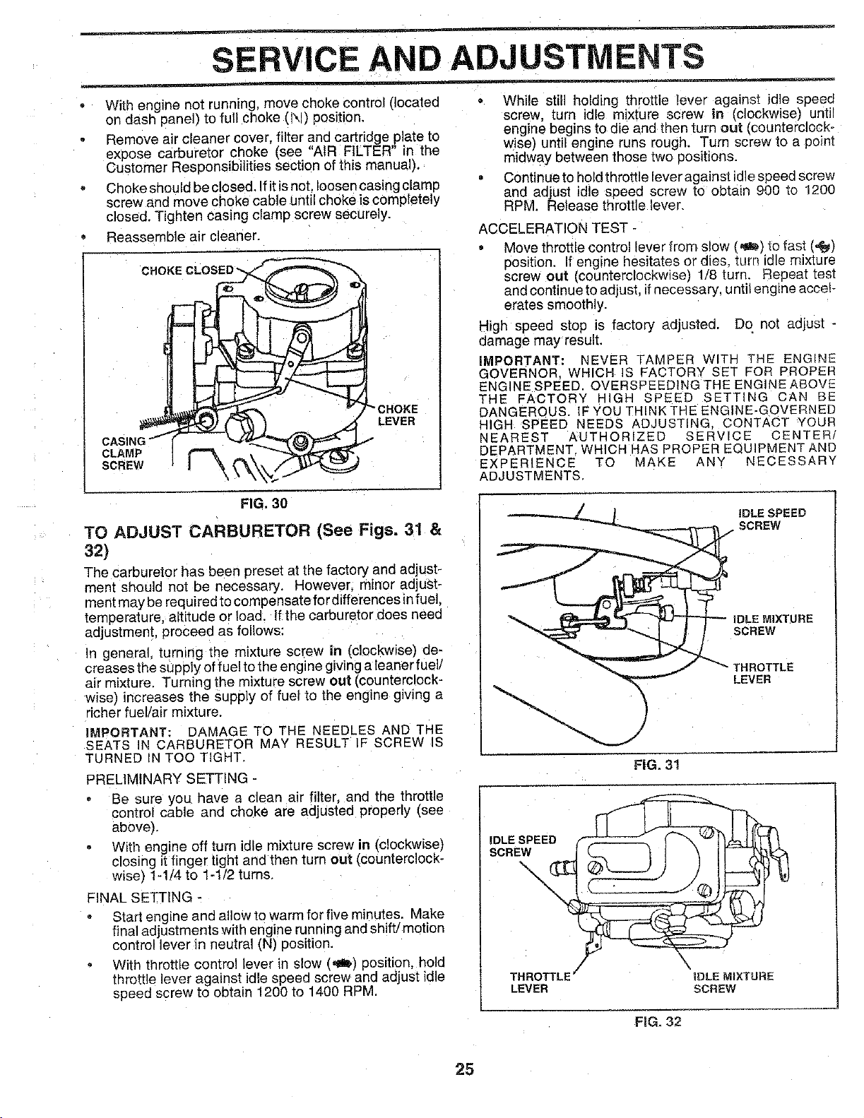
TO ADJUST CHOKE CONTROL (See Fig. 30)
The choke control has been oreset at the factory and
adjustment should not be necessary. Check ad ustment as
described oelow before loosening cable. If adjustment is
necessary, proceed as follows:
SERVICE AND
With engine not running, move choke control (located
on dash panel) to full choke (N) position.
Remove air cleaner cover, filter and cartridge plate to
expose carburetor choke (see "AtR FILTER" in the
Customer Responsibilities section of this manual).
Choke should be closed. If it isnot. loosen casing clamp
screw and move choke cable until choke is completely
closed. Tighten casing clamp screw securely.
Reassemble air cleaner.
CLAMP
SCREW
LEVER
FIG. 30
TO ADJUST CARBURETOR (See Figs. 31 &
32)
The carburetor has been preset at the factory and adjust-
ment should not be necessary. However, minor adjust-
ment may be required to compensatefor differences in fuel.
temperature, altitude or load, If the carburetor does need
adjustment, proceed as follows:
In general, turning the mixture screw in (clockwise) de-
creases the supply of fuel to the engine giving a leaner fuel/
air mixture, Turning the mixture screw out (counterclock-
wise) increases the supply of fuel to the engine gwing a
richer fuel/air mixture.
IMPORTANT: DAMAGE TO THE NEEDLES AND THE
SEATS N CARBURETOR MAY RESULT IF SCREW IS
TURNED IN TOO TIGHT,
PRELIMINARY SETTING -
Be sure you have a clean air filter and the throttle
control cable and choke are adjusted properly (see
above).
With engine off turn idle mixture screw in (clockwise)
closing it finger tight and then turn out (counterclock-
wise) 1-1/4 to 1-1/2 turns.
FINAL SETTING -
Start engine and allow to warm for five minutes, Make
final adjustments with engine running and shift/motion
control lever n neutral (N) position.
With throttle control lever in slow (,_I) position, hold
throttle lever against idle speed screw and adjust idle
speea screw to obtain 1200 to 1400 RPM.
ADJUSTMENTS
While still holding throttle lever against idle speed
screw, turn idle mixture screw in (clockwise) until
engine begins to die and then turn out _counterclock _
wise) until engine runs rough. Turn screw to a point
midway between those two positions.
Continue to hold throttle lever against idlespeed screw
and adjust idle speed screw to obtain 900 to 1200
RPM. Release throttle lever.
ACCELERATION TEST -
Move throttle control lever from slow (_/to fast (,_)
position, If engine hesitates or dies turn idle mixture
screw out (counterclockwise} 1/8 turn. Reoeat test
and continue to adjust, ifnecessary, until engine acceh
erates smoothly.
High speed stop is factory adjusted. Do not adjust -
damage may result.
IMPORTANT: NEVER TAMPER WITH THE ENGINE
GOVERNOR. WHICH IS FACTORY SE'r FOR =ROPER
ENGINE SPEED, OVERSPEEDING THE ENGINE ABOVE
THE FACTORY HIGH SPEED SETTING CAN £E
DANGEROUS. IF YOU THINK THE ENGINE-GOVERNED
HIGH SPEED NEEDS ADJUSTING CONTACT YOUR
NEAREST AUTHORIZED SERVICE CENTER/
DEPARTMENT WHICH HAS PROPER EQUIPMENT AND
EXPERIENCE TO MAKE ANY NECESSARY
ADJUSTMENTS,
iDLE SPEED
SCREW
iDLE MIXTURE
SCREW
THROTTLE
LEVER
iDLE SPEED
SCREW_
THROTTLE /
LEVER
IDLE MIXTURE
SCREW
FiG. 32
25
STORAGE
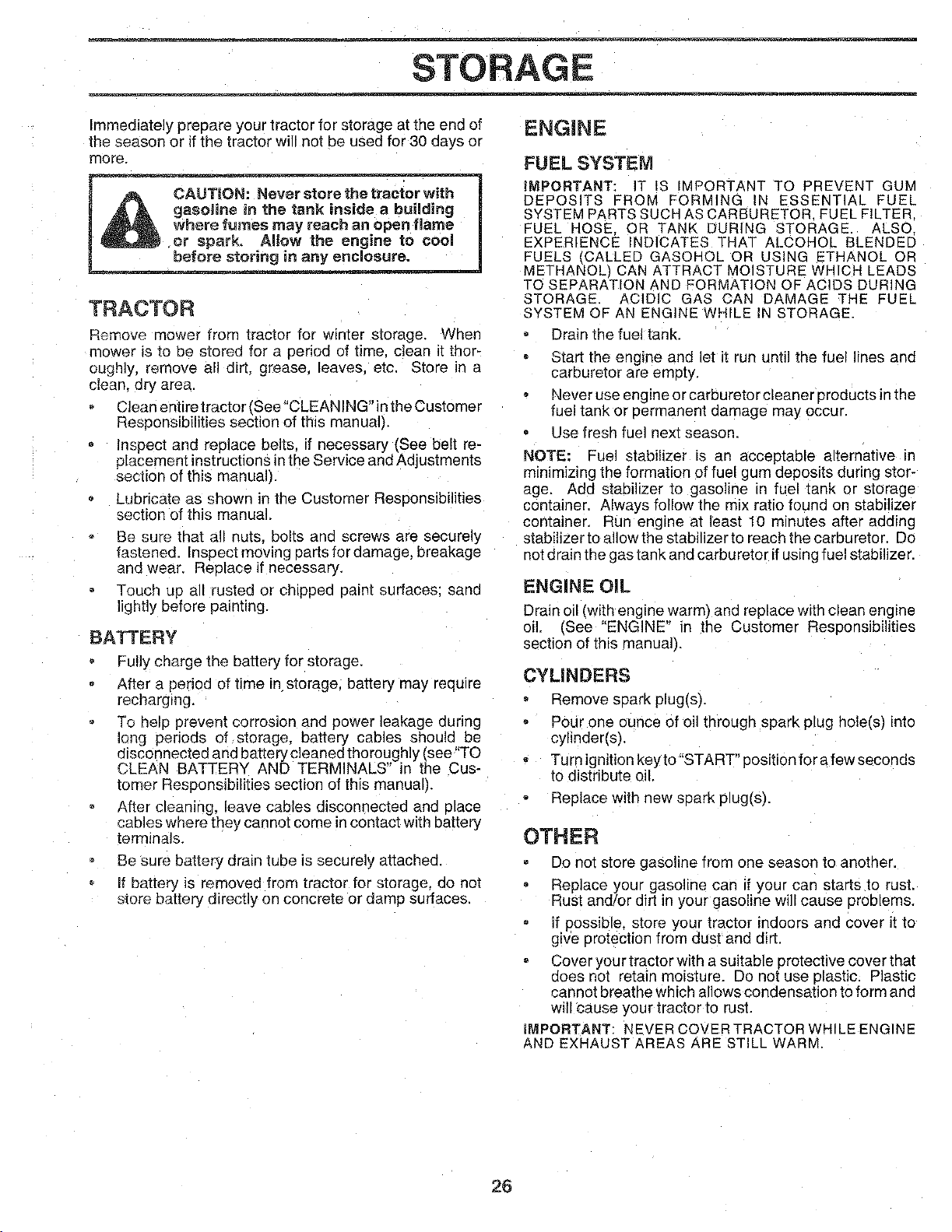
Immediately prepare your tractor for storage at the end of
the season or if the tractor will not be used for 30 days or
more.
_re the tract_ with"
,_ _ _nk inside a building
where fumes may reach an open flame
_t_ the engine to cool I
in enclosure. _ .
TRACTOR
Remove mower trom tractor for winter storage. When
mower is _oDe stored for a period of time clean it thor-
oughly, remove all dirt. grease, leaves, etc. Store in a
clean, cry area.
Clean entire tractor (See"CLEANING"in the Customer
Responsibilities section of this manual).
Inspect and replace belts if necessary (See belt re-
placement instructions in the Service and Adjustments
section of this manual).
Lubricate as shown in the Customer Resoonsibilities
section of this manual.
Be sure that a!l nuts. bolts and screws are securely
fastened. Inspect moving partsfordamage, breakage
and wear. Reolace if necessary.
Touch up all rusted or chipped paint surfaces: sand
lightly before painting.
BAKERY
Fully charge the battery for storage.
After a period of time in storage, battery may require
recharging.
To help prevent corrosion and power leakage during
long periods of storage, battery cables should be
disconnected and battery cleaned thoroughly (see "TO
CLEAN BATTERY AND TERMINALS" in the Cus-
tomer Responsibilities section of this manual).
After cleaning, leave cables disconnected ana p_ace
cables where they cannot come in contact with battery
terminals.
Be sure battery drain tube is securely attached.
If battery is removed from tractor for storage, do no1
store battery directly on concrete or damp surfaces.
ENGINE
FUEL SYSTEM
IMPORTANT: IT IS IMPORTANT TO PREVENT GUM
DEPOSITS FROM FORMING IN ESSENTIAL :UEL
SYSTEM PARTS SUCH AS CARBURETOR. FUEL FILTER
FUEL HOSE. OR TANK DURING STORAGE. ALSQ
EXPERIENCE INDICATES THAT ALCOHOL BLENDED
FUELS (CALLED GASOHOL OR USING ETHANOL OR
METHANOL CAN ATTRACT MOISTURE WHICH LEADS
TO SEPARATION AND FORMATION OF ACIDS DURING
STORAGE. ACIDIC GAS CAN DAMAGE THE FUEL
SYSTEM OF AN ENGINE WHILE IN STORAGE.
Drain the fue tank.
Start the engine and let it run until the fuel lines and
carburetor are emuty,
Never use engine or carburetor cleaner products in the
fuel tank or permanent damage may occur.
Use fresh fuel next season.
NOTE: Fuel stabilizer is an acceptable alternative in
minimizing the formation of fuel gum deposits during stor-
age. Add stabilizer to gasoline in fuel tank or storage
container. Always follow the mix ratio found on stabilizer
container. Run engine at least 10 minutes after adding
stabilizer to allow the stabilizer to reach the carburetor. Do
not drain the gas tank and carburetor ifusing fuel stabilizer.
ENGINE OiL
Drain oil (with enc ne warm_ and replace with clean engine
oil. _See "ENGINE" n the Customer Responsibilities
section of this manual).
CYLINDERS
Remove spark plug(s).
Pour one ounce of oil through spark plug hole(s', nto
cylinder(s),
Turn ignitionkeyto "START" position fora few seconds
to distribute oil,
Replace with new spark plug(s).
OTHER
Do not store gasoline from one season to another.
Replace your gasoline car" If your can starts to rust.
Rust and/or dirt in your gasoline will cause proutems,
If possible, store your tractor indoors and cover it to
give protection from dust and dirt,
Cover your tractor with a suitable protective cover that
does net retain moisture. Do not use plastic. Plastic
cannot breathe which allows condensation to form and
will cause _our tractor to rust.
IMPORTANT: NEVER COVER TRACTOR WHILE ENGINE
&ND EXHAUST AREAS ARE STILL WARM.
26

TROUBLESHOOTING POINTS
PROBLEM
-- =
Will not start
Hard to start
Engine will not turn over
Engine clicks but will not
start
Loss of power
Excessive vibration
CAUSE
1. Out of fuel.
2. Engine not "CHOKED" properly.
3. Engine floode¢
4. Bad sparkplug.
5. Dirty air filter.
6. Dirty fuelfiger
7. Water in fuel.
8. Loose or damaged widng.
9. Carburetor out of aaiustment.
10. Engine valves out of adjustmenl
1 Dirty air filter,
2 Bad seark plug.
3 Weak or dead battery.
,1 Dirty fuel filter.
5. Stale or dtrty fuel.
6 Loose or damaged widng.
7. Carburetor out of adjustment.
8 Engine vatves out of adjustment.
f. Clutch/brake 3edal not denressed
2. Attachment clutch is engagea.
3. Weak or dead battery
4. BIown fuse.
5. Corroded battery [ermma_s
6. Loose or damagea wlnng.
7. Faulty ignition swacn.
8. Faulty solenoid or starter.
9. Faulty oeerator presence switcl esl.
t. Weak or dead battery
2. Corroded battery termmals.
3. Loose or damaged wiring.
4. Faulty solenoid or starer.
Cutting too mucn grass/too fast,
2. Throttle n "CHOKE" position
3. Build-up of grass, leaves and trash under mower.
_t Dirty air filter.
5 Low oil level/dirty oil.
6 =aulty spark ptug.
7 Dirty fuel filter.
8 Stale or dirty rue
9 Water in fuel.
10. Spark plug wire loose.
11. Dirty engine air screen/fins.
12 Dirty/clogged muffler
13. Loose or damaged wiring
14 Carburetor out of adjus[ment.
15 Engine valves out of adjustment.
l Worr Dent or loose Diode.
2 Bent blade manare
3. Loose/damaged 3ares
CORRECTION
1 Fill fuel tank.
2. See "TO START ENGINE" in Oeeratlon section.
3, Wait several minutes before attempting to start.
a Reolace seark plug,
5. Clean/feE ace air fitter.
6. Replace fuel filter.
7. Drain fuel tank and carburetor refill tank with fresh
gasoline and replace fuel filter.
8, Check all wiring.
9. Contact an authorized service center/department
10. Contact an autnorlzea service center/deBaRment
1 Clean/replace air filter,
2. Reelace spark plug.
3, Recharge or replace eattery.
4, Replace tus Iilter
5, Drain fuel tank and refill with tresf gasoline.
6. Check all wiring,
7 Contact an autnonzea service center/department
8, Contact an aumonzed service center/department
1 3eDress clutch/brake pedal
2 Disengage a[tacnment clut@
3 Recharge or replace eattery.
4 Replace fuse.
5 Clean battery [ermina{s.
6 Check all wiring.
7 Check/replace _gnition switch
8 CheckireB ace solenoid or starter.
9 Contact an authorized service center/department.
1. Recharge or replace battery.
2. Clean batter, [ermma_s,
3. Check all wJdng.
4. Check/rat ace solenoid or starter
t. Set in _Higher Cut" 3osition/reduce sDeea
2. Adjust throttle control.
3 Clean underside of mower housing
,t Clean/replace air filter
5. Check oil level/change o
6. Clean and regap or change spark plug.
7. Replace fuel fiJter,
8. Drain fuel tank anG rel with fresh gasotme.
9. Drain fuel tank and carburetor refill tank wif_" fresl-
gasoline and reolace fuel Nter.
10 Connect and tighten spark plug wLre
11. Clean engme air screen/fins
12. Clean/replace muffler.
13. Check allwiring.
14. Contact an authorized service center/deoartment.
15. Contact an authorized service center/department.
1 Replace blade Tighten blade bolt
2. Replace blade mandre
3. Tighten loose part(s). Replace damaged Darts.
_ -- =
27

TROUBLESHOOTING POINTS
PROBLEM
Engine continues to run
when operator Ieaves seat
with attachment clutch
engaged
Poor cut - uneven
Mower blades wii_ not
rotate
Poor grass discharge
Headlight{e) not working
(_fso equipped)
_atteq will not charge
_ine "backfires"
when turnlng engine
"OP_:"
CAUSE
1. Faulty operator-safety presence control system.
1 Worn bent or loose blade
2. Mower deck not level
3. Buildup of grass. _eave_ and [rash under mower,
4. Bent blade mandrel
5. Cloggeo mower deck vent holes from buildue of
grass, leave_ and trash around mandrels.
1 Obstruction in clutch mechanism
2 Worn/damaged mower drive belt
3 Frozen idler euliev.
a Frozen blade mandrel.
CORRECTION
Ch_ck wiring, sw_[cne,o and connect=ons. If not
.orJected contact an authorized service center/
delver[merit.
Rec ace blade Tigmen u due bolt
2. Level mower deck
3. Clean underside of mower housing.
4. Rec ace Blade mandrel
5. Ctean arounu mandrels to eden ven[ hOles.
1. Remove obstruction.
2. RGCace mower drive Dell
3. Reptace idle_ pulley,
Reolace blade mandre
En line speed too stow
2 Travel speed too fast
3 Wet grass.
4. Mower deck not leveI
5. LOW/uneven r_rea. oressure.
6 Wor_ bent or loose blade
l. Place throttle controI in "FAST" posttlor
2. Shirt to slower sueen
3. Allow grass to dry oeTore mowing.
zl Leve_mower deck
5. Check tires tor proper air pressure.
6. Reulace/sharoen olaoe Tighten blade bolt
7. Buildup ot grass eaves and irasn unaer mower
8. Mower drive belt worn
9 Blades improperly qstauea
10. imDrooer DidOes Jeed
t t. Clogged mower deck vent holes from buildup of
grass, leaves, anrJtrash around mandrels
Switch is "OFF
2. BulbIs 3urned out.
3 Faulty ilgi3t switch.
4. Loose or ctamaged wlnng.
5 Blown fuse
1. Bad battery celltsl,
2. Poor cable connections.
3 Faulty regulator (if so equipped).
,1 Faulty alternator,
1. Engine throttle control not set at"SLOW"
oosJuon for 30 seconds before stopping engine
Clean underside of mower housir ]
8. Replace mower orlve beib
9, Reinstall blades sharp edge oown
1O. ReD ace with blades listed _nIdlemanual.
Clean around mandrels to eDen vent notes
]. Turn switch "ON".
2. Replace bulb(s)
3. ChecWreelace light switch
Check wirir _ and connections.
5. Reelace fuse.
Reblace batter:
2. Check/clean all connections.
3, Replace regulator
ReuJace alterna[or
Move throttle control to "SLOW" OOSltJonana allOW
to idle for 30 seconds eeTore stopping e- _lne
28
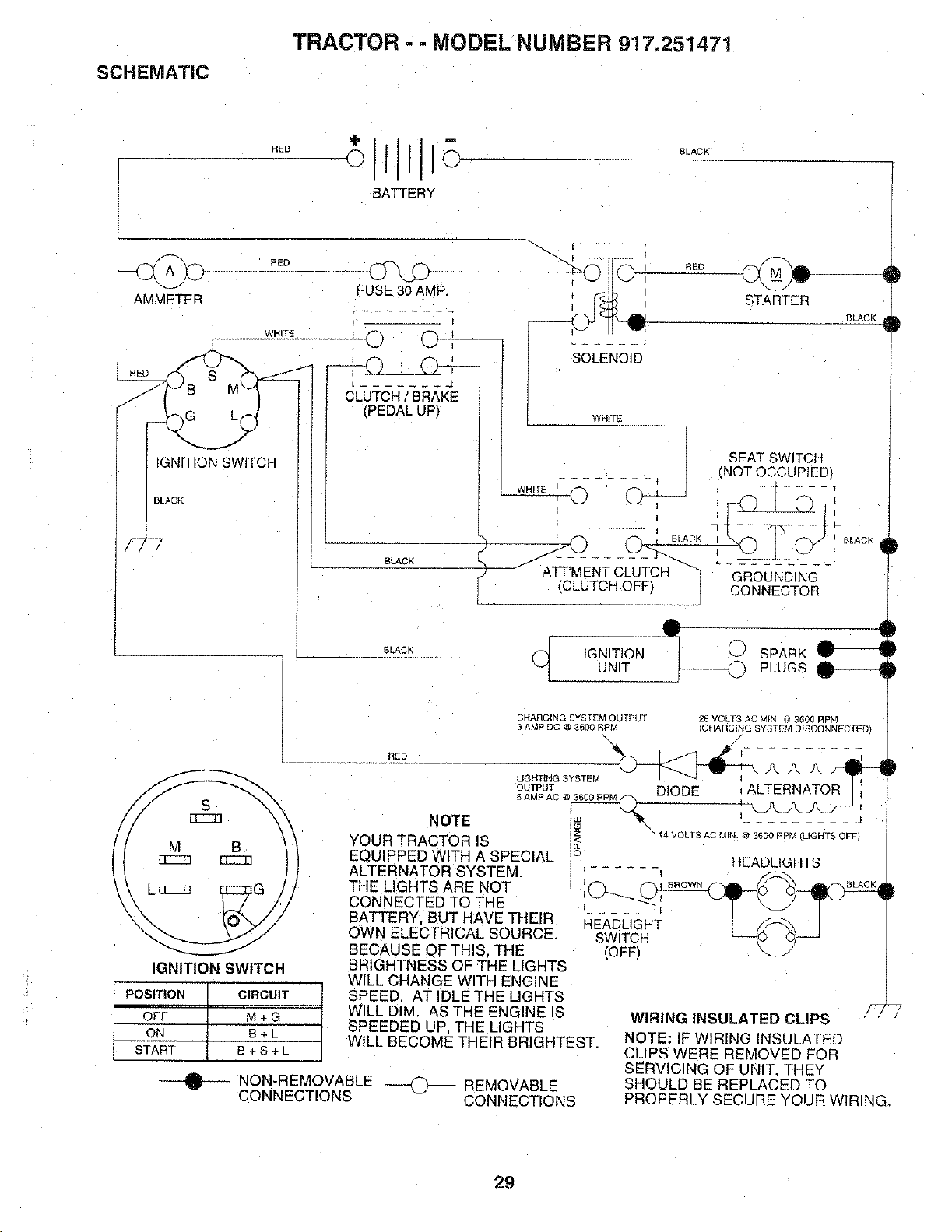
SCHEMATIC
TRACTOR -- MODEL NUMBER 917.251471
RED
BATTERY
BLACK
©
RED
I MMETER WHITE
RED __
G_C H
LACK
FUSE30 AMP.
©
CLUTCH BRAKE
(PEDALUP)
SOLENOID
BLAC_
SLACK
RED
STARTER
BLACK
WHITE
SEATSWITCH
• , | (NOT OCCUPIED
(CLUTCHOFF, CONNECTOR
,GN, ,ONSPARK
UNIT PLUGS O------_
CHARGING SYSTEM OUTPUT
3 AMP DC @ 3600 RPM
28 VOLTS AC MIN _ 3600 RPM
_HARGING SYSTEM D ]CONNECTED/
RED
B
ECC_
IGNITION SWITCH
POSITION CIRCUIT
OFF M + G
ON B+L
START B + S + L
UGHTING SYSTEM
OUTPUT DIODE ALTERNATOR
5 AMP AC @ 3600 RPM
NOTE 1_ _ - - "
YOUR TRACTOR IS IZI_ " 14 VOLTS AC MIN @3600 RPM LIGHTS OFF)
EQUIPPED WITH A SPECIAL I° H_n/iCWTq
ALTERNATOR SYSTEM• I _...... _ _Z_ ....
THE LIGHTS ARE NOT _ _.BROWN_ _" _ _%BLACKd
CONNECTED TO THE _,_'_'_-! _ _ J_q_- _
BATTERY, BUT HAVE THEIR HE_ASI_IGI'tT ! _ I
OWN ELECTRICAL SOURCE. SWITC_I" [-_(_ _ J
BECAUSE OF THIS. THE (OFF_ _J
BRIGHTNESS OF THE LIGHTS
WILL CHANGE WITH ENGINE
SPEED. AT IDLE THE LIGHTS
WILL DIM. AS THE ENGINE IS
SPEEDED UP. THE LIGHTS
WILL BECOME THEIR BRIGHTEST.
...._ NON-REMOVABLE _ -_ REMOVABLE
CONNECTIONS CONNECTIONS
WIRING INSULATED CLIPS
NOTE: IF WIRING INSULATED
CLIPS WERE REMOVED FOR
SERVICING OF UNIT. THEY
SHOULD BE REPLACED TO
PROPERLY SECURE YOUR WIRING_
29
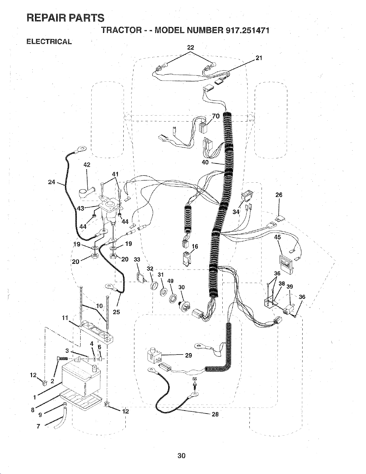
REPAIR PARTS
TRACTOR - - MODEL NUMBER 917.251471
ELECTRICAL
22
12
24
42
44
,19
20 33
/
25
11
3
40
16
32
3t
49
30
26
7
3O
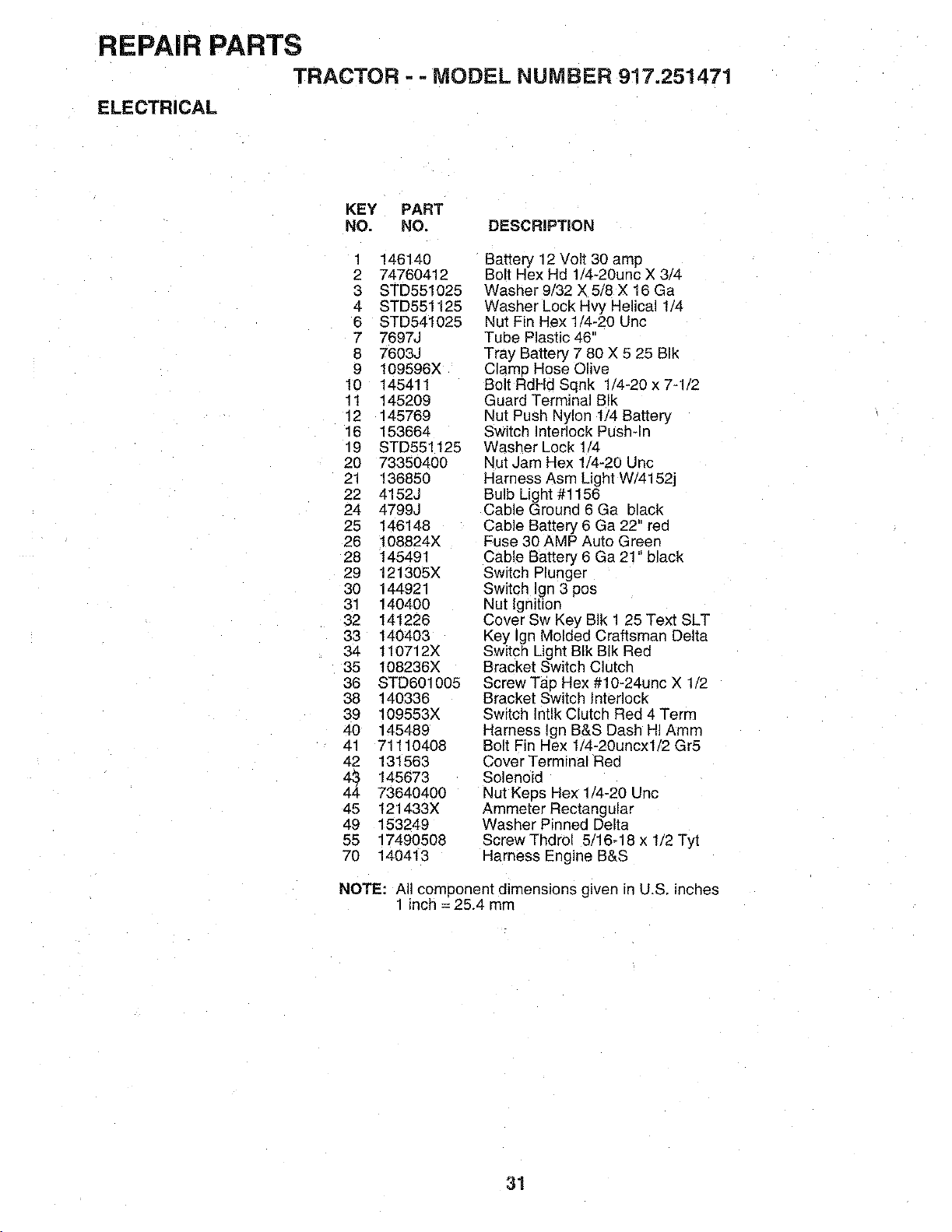
REPAIR PARTS
TRACTOR - - MODEL NUMBER 917.251471
ELECTRICAL
KEY PART
NO. NO. DESCRIPTION
1 146140
2 74760412
3 STD551025
4 STD551125
6 STD541025
7 7697J
8 7603J
9 109596X
10 145411
11 145209
12 145769
16 153664
19 STD551125
20 73350400
21 136850
22 4152J
24 4799J
25 146148
26 108824X
28 145491
29 121305X
30 144921
31 140400
32 141226
33 140403
34 110712X
35 108236X
38 STD601005
38 140336
39 109553X
40 145489
41 71110408
42 131563
_ 145673
73640400
45 121433X
49 153249
55 17490508
70 140413
Battery 12 Volt 30 amp
Bolt Hex Hd 1/4-20unc X 3/4
Washer 9/32 X 5/8 X 16 Ga
Washer Lock Hvy Helical 1/4
Nut Fin Hex 1/4-20 Uric
Tube Plastic 46
Tray Battery 7 80 X 5 25 BIk
Clamp Hose Olive
Bolt RdHd Sqnk 1/4-20 x 7-1/2
Guard Terminal BIk
Nut Push Nylon 1/4 Battery
Switch Interlock Push-In
Washer Lock 1/4
Nut Jam Hex 1/4-20 Uric
Harness Asm Light W/4152j
Bulb Light #1156
Cable Ground 6 Ga black
Cable Battery 6 Ga 22" red
Fuse 30 AMP Auto Green
Cable Battery 6 Ga 21" black
Switch Plunger
Switch Ign 3 pos
Nut Ignition
Cover Sw Key BIk 1 25 Text SLT
Key Ign Molded Craftsman Delta
Switch Light BIk BIk Red
Bracket Switch Clutch
Screw Tap Hex #10-24unc X 1/2
Bracket Switch Jnterlock
Switch lntlk Clutch Red 4 Term
Harness lgn B&S Dash HI Amm
Bolt Fin Hex 1/4-20uncxl/2 Gr5
Cover Terminal Red
Solenoid
Nut Keps Hex 1/4-20 Uric
Ammeter Rectangular
Washer Pinned Delta
Screw Thdro! 5/16-18 x 1/2 Tyt
Harness Engine B&S
NOTE: All component dimensions given in U.S. inches
1 inch = 25.4 mm
31
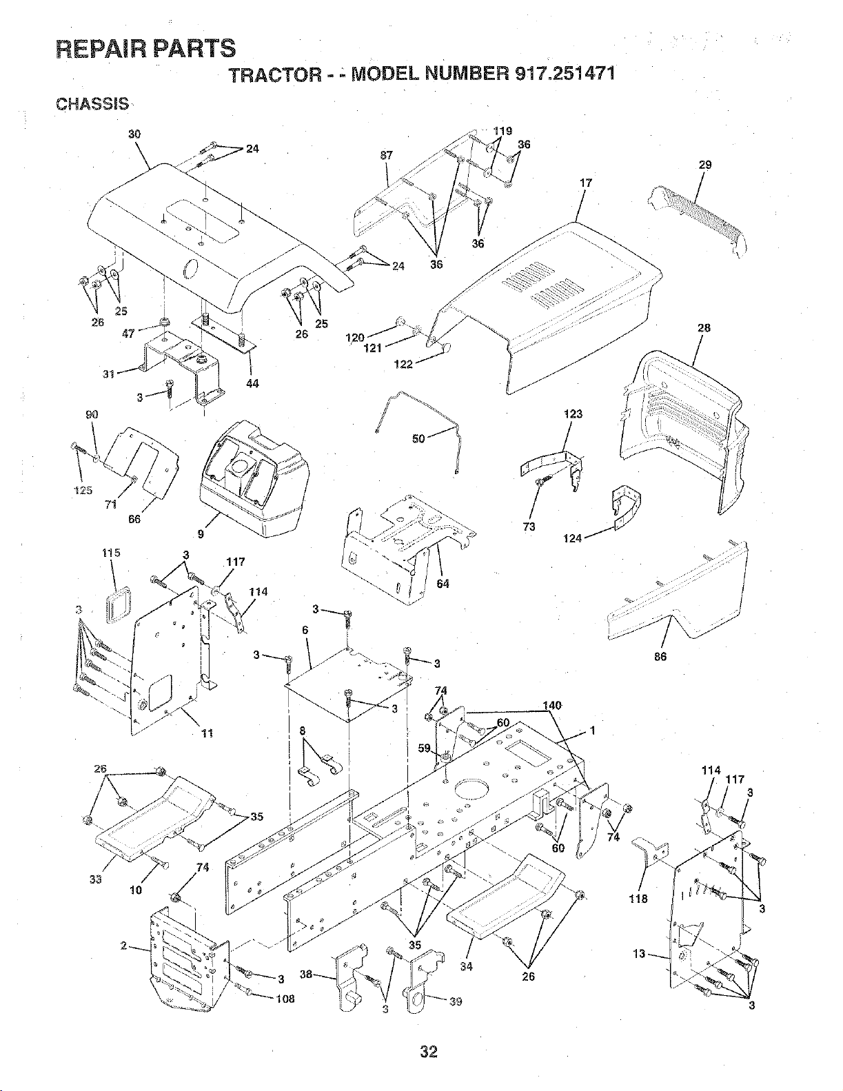
REPAIR PARTS
TRACTOR -- MODEL NUMBER 917.251471
CHASSIS
3!
3_ 44
9O
125
3 •
71
88
115
9
3
117
114
25
26
8
121
_o.J4
17
-)
t23
64
88
33
10
118
|08
26
29
/
28
114
117
3
3
32
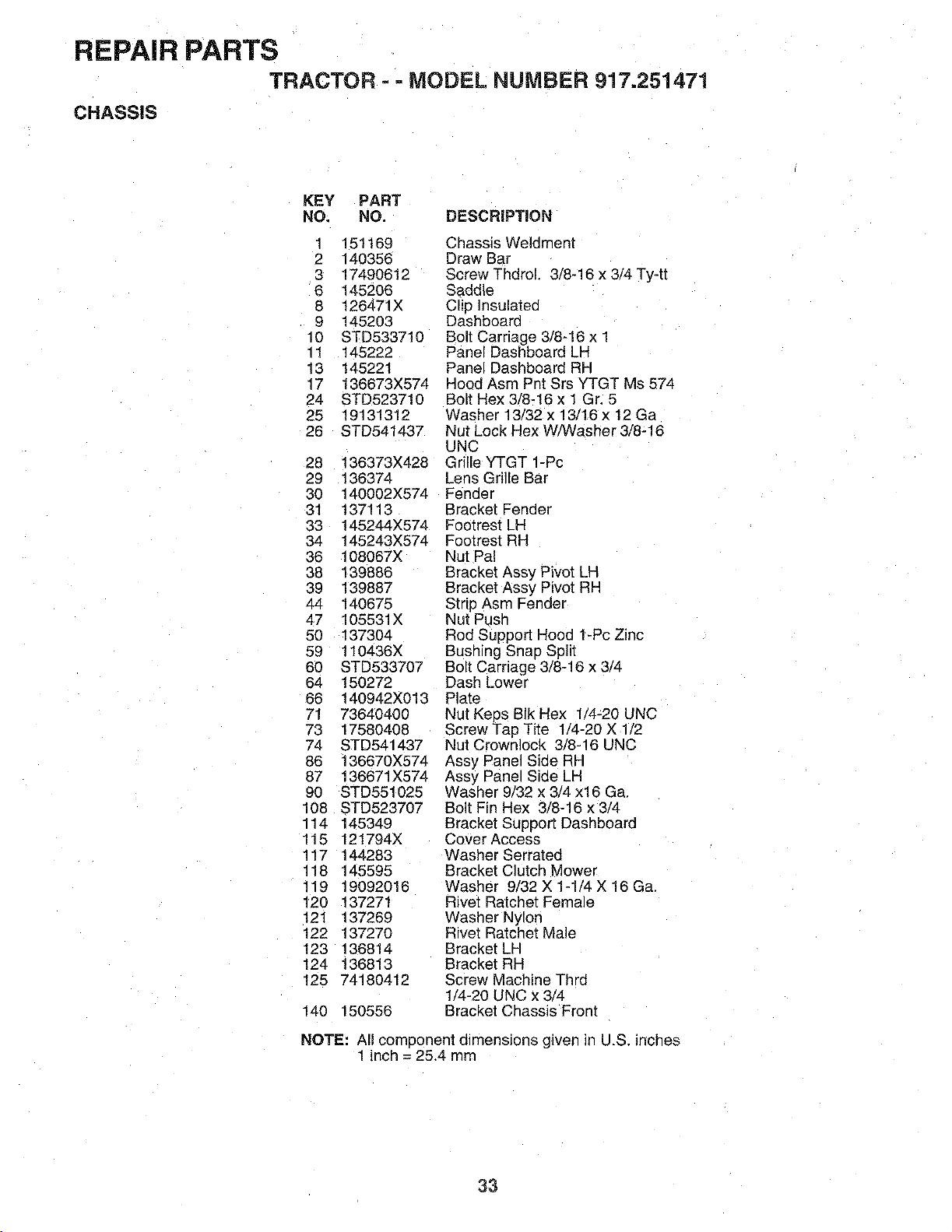
REPAIR PARTS
TRACTOR - - MODEL NUMBER 917.251471
CHASSIS
KEY PART
NO. NO. DESCRiPTiON
1 151169 Chassis Weldment
2 140356 Draw Bar
3 17490612 Screw Thdrol. 3/8-16 x 3/4 Ty-tt
6 145206 Saddle
8 t26471X Clip Insulated
9 145203 Dashboard
10 STD533710 Bolt Carriage 3/8-!6 x 1
11 145222 Panel Dashboard LH
13 145221 Panel Dashboard RH
17 136673X574 Hood Asm Pnt Srs YTGT Ms 574
24 STD523710 Bolt Hex 3/8-16 x 1 Gr. 5
25 19131312 Washer 13/32 x 13/16 x 12 Ga
26 STD541437 Nut Lock Hex W/Washer 3/8-16
UNC
28 136373X428 Grille YTGT 1-Pc
29 136374 Lens Grille Bar
30 140002X574 Fender
31 137113 Bracket Fender
33 145244X574 Footrest LH
34 145243X574 Footrest RH
36 108067X Nut Pa!
38 139886 Bracket Assy Pivot LH
39 139887 Bracket Assy Pivot RH
ztzt 140675 Strip Asm Fender
47 105531X Nut Push
50 137304 Rod Support Hood 1-Pc Zinc
59 110436X Bushing Snap Split
60 STD533707 Bolt Carriage 3/8-16 x 3/4
64 150272 Dash Lower
66 140942X013 Plate
71 73640400 Nut Keps BIk Hex 1/4_20 UNC
73 17580408 Screw Tap Tite 1/4-20 X 1/2
74 STD541437 Nut Crownlock 3/8-16 UNC
86 136670X574 Assy Panel Side RH
87 136671X574 Assy Panel Side LH
90 STD551025 Washer 9/32 x 3/4 x16 Ga.
108 STD523707 Bolt Fin Hex 3/8-16 x 3/4
114 145349 Bracket Support Dashboard
115 121794X Cover Access
117 144283 Washer Serrated
118 145595 Bracket Clutch Mower
119 19092016 Washer 9/32 X 1-1/4 X 16 Ga.
120 137271 Rivet Ratchet Female
121 137269 Washer Nylon
122 137270 Rivet Ratchet Male
123 136814 Bracket LH
124 136813 Bracket RH
125 74180412 Screw Machine Thrd
1/4-20 UNC x 3/4
140 150556 Bracket Chassis Front
NOTE: All comoonent dimensions gwen in U.S. inches
1 inch = 25.4 mm
33
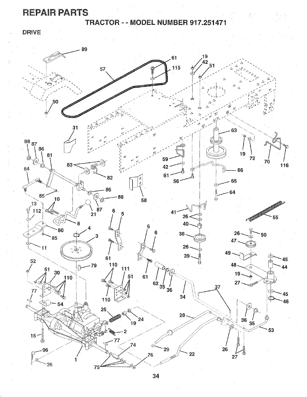
REPAIR PARTS
TRACTOR - =MODEL NUMBER 917.251471
DRIVE
31
/
/
81
52
77
19
42 5!
57 t15 , /
83 ' . - :"
86
58
61
110
19
87 6
21
77 74
/
1
75
v, _r
19 _ .
72 701
/
116
_64
26_^
47 ,._._
37
\
\
36
27
45
46
53
34
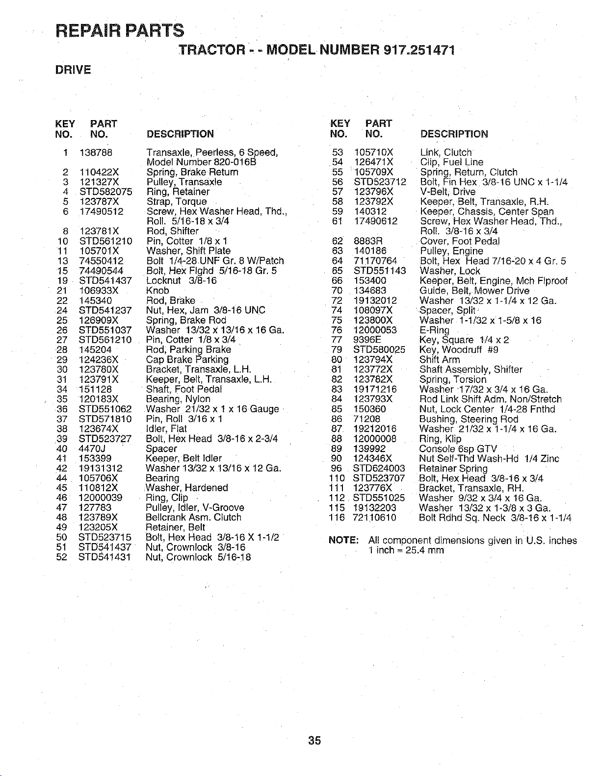
REPAIR PARTS
TRACTOR - =MODEL NUMBER 917.251471
DRIVE
KEY PART KEY PART
NO. NO. DESCRIPTION NO. NO. DESCRIPTION
2
3
4
5
6
8
10
11
13
15
19
21
22
24
25
26
27
28
29
3O
31
34
35
36
37
38
39
40
41
42
44
45
46
47
48
49
50
51
52
138788
t10422X
121327X
STD582075
123787X
17490512
123781X
STD561210
105701X
74550412
74490544
STD541437
t06933X
145340
STD541237
126909X
STD551037
STD561210
145204
124236X
123780X
123791X
151128
120183X
STD551062
STD571810
123674X
STD523727
4470J
153399
19131312
105706X
110812X
12000039
127783
123789X
123205X
STD523715
STD541437
STD541431
Transaxle. Peerless. 6 Speed, 53 105710X
Model Number 820-016B 54 126471X
Spring, Brake Return 55 105709X
Pulley, Transaxle 56 STD523712
Ring, Retainer 57 123796X
Strap, Torque 58 123792X
Screw -lex Washer Head. Thd.. 59 140312
Roll. 5/16-18 x 3/4 61 17490612
Rod. Shifter
Pin. Cotter 1/8x 1 62 8883R
Washer. Shift Plate 63 140186
Bolt lf4-28 UNF Gr. 8 W/PatcP 64 71170764
Bolt. Hex FIghd 5/16-18 Gr. 5 65 STD551143
Locknut 3/8-16 66 153400
Knob 70 t 34683
Rod. Brake 72 19132012
Nut, Hex. Jam 3/8-16 UNC 74 108097X
Spring, Brake Rod 75 123800X
Washer 13/32 x 13/16 x 16 Ga. 76 12000053
Pin, Cotter 1/8 x 3/4 77 9396E
Rod. Parking Brake 79 STD580025
Cap Brake Parking 80 123794X
Bracket. Transaxle. L.H. 81 123772X
Keeper, Belt. Transaxle. L.H. 82 123782X
Shaft Foot Pedal 83 19171216
Bearing, Nylor 84 123793X
Washer 21/32 x 1 x 16 Gauge 85 150360
Pin, Roll 3/16xi 86 71208
Idler. Flat 87 19212016
Bolt Hex Head 3/8-16 x 2-3/4 88 12000008
Spacer 89 139992
Keeper. Belt Idler 90 124346X
Washer 13/32 x 13/16 x 12 Ga, 96 STD624003
Bearing 110 STD523707
Washer. Hardened 111 123776X
Ring, Clip 112 STD551025
Pulley, Idler. V-Groove 115 19132203
Bellcrank Asm. Clutct* 116 72110610
Retainer Belt
Bolt. Hex Head 3/8-16 X 1-1/2
Nut. Crownlock 3/8-16
Nut. Crownlock 5/16-18
Link. Clutch
Clip, Fuel Line
Spring, Return. Clutch
Bolt. Fin Hex 3/8-16 UNC x 1-1/4
V-Belt. Drive
Keeeer. Belt. Transaxle. R.H.
Keeeer. Chassis. Center Span
Screw Hex Washer Head. Thd.,
Roll. 3/8-16 x 3/4
Cover. Foot Peda,
Pulley, Engine
Bolt. Hex Head 7/16-20 x 4 Gr. 5
Washer. Lock
Keeper. Belt. Engine. Mch Flproof
Guide. Belt. Mower Drive
Washer 13/32 x 1-1/4 x 12 Ga.
Spacer, Split
Washer 1-1/32 x 1-5/8 x 16
E-Ring
Key, Square 1/4 x 2
Key, Woodruff #9
Shift Arm
Shaft Assembly, Shifter
Spring, Torsion
Washer 17/32 x 3/4 x 16 Ga.
Rod Link Shift Adm. Non/Stretch
Nut. Lock Center 1/4-28 Fnthd
Bushing, Steering Rod
Washer 21/32 x 1-1/4 x 16 Ga.
Ring, Klip
Console 6se GTV
Nut Self-Thd Wash-Hd 1/4 Zinc
Retainer Spring
Bolt. Hex Head 3/8-16 x 3/4
Bracket. Transaxle, _H
Washer 9/32 x 3/4 x 16 Ga.
Washer 13/32 x 1-3/8 x 3 Ga.
Bolt Rdhd Sq. Neck 3/8-16 x 1-1/4
NOTE: All comeonent dimensions given in U.S. inches
1 inch = 25.4 mm
35
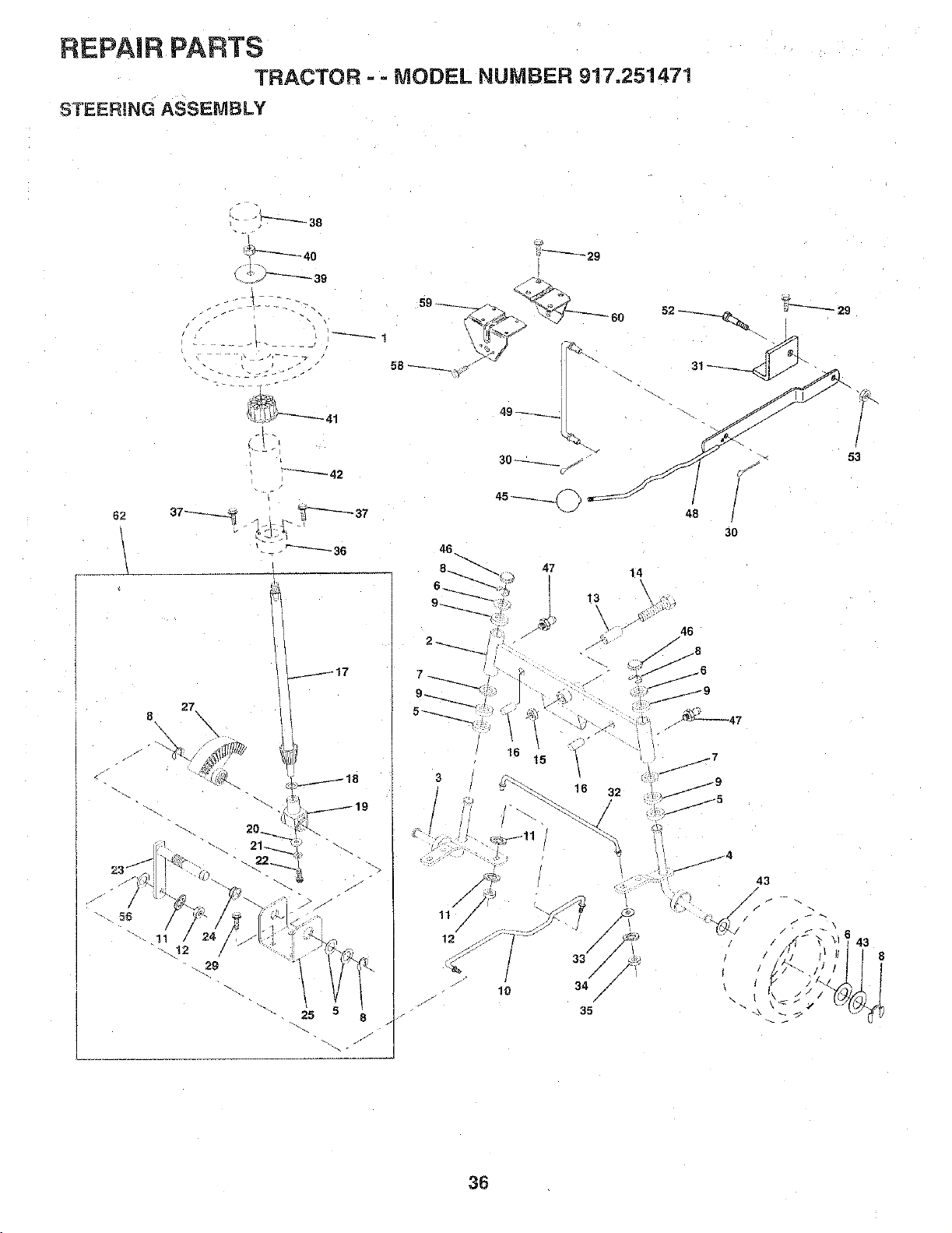
REPAIR PARTS
TRACTOR =- MODEL NUMBER 917.251471
STEERING ASSEMBLY
j17
47
15
14
\
13
48
30
J
i 46
-< ,i_
,../ 8
jJ
/9
• /
J . "
¢.. 16 32
,g
A_
33/ /"
lO 34//
35
j7
i
j9
i
53
36
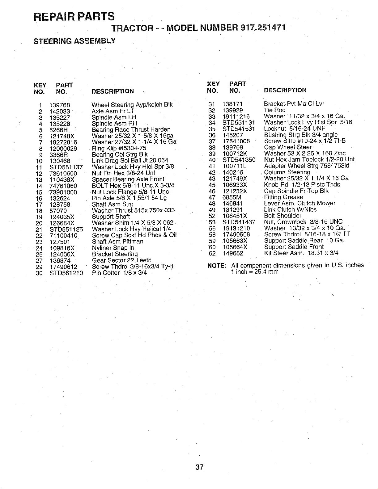
REPAIR PARTS
TRACTOR - - MODEL NUMBER 917.251471
STEERING ASSEMBLY
KEY PART KEY PART
NO. NO. DESCRIPTION NO, NO. DESCRiPTiON
1 139768 Wheel Steering Ayp/kelch BIk 31 138171
2 142033 Axle Asm Fr LT 32 139929
3 135227 SpindleAsmLH 33 19111216
4 135228 Spindle Asm RH 34 STD551131
5 6266H Bearing Race Thrust Harden 35 STD541531
6 121748X Washer 25/32 X 1-5/8 X 16ga 36 145207
7 19272016 Washer 27/32 X 1-1/4 X 16 Ga 37 17541008
8 12000029 Ring Klip #t5304-75 38 139769
9 3366R Bearing Col Strg BIk 39 100712K
10 130468 Link Drag Sol Ball Jt 20 064 40 STD541350
11 STD551137 Washer Lock Hvy HIcl Spr 3/8 41 100711L
12 73610600 Nut Fin Hex 3/8-24 Unf 42 140216
13 110438X Spacer Bearing Axle Front 43 121749X
14 74761060 BOLT Hex 5/8-11 Uric X 3_3/4 45 106933X
15 73901000 Nut Lock Flange 5/8-11 Unc 46 121232X
16 132624 Pin Axle 5/8 X 1 55/1 54 Lg 47 6855[v'
17 128758 Shaft Asm Strg 48 146841
18 57079 Washer Thrust 515x 750x 033 49 131291
19 124035X Support Shaft 52 106451X
20 126684X Washer Shim 1/4 X 5/8 X 062 53 STD541437
21 STD551125 Washer Lock Hvy Helical 1/4 56 19131210
22 71100410 Screw Cap Sckt Hd Phos & Oil 58 17490508
23 127501 Shaft Asm Pittman 59 105663X
24 109816X Nyliner Snap In 60 105664X
25 124036X Bracket Steering 62 149682
27 136874 Gear Sector 22 Teeth
29 17490612 Screw Thdrol 3/8-16x3/4 Ty-tt
30 STD561210 Pin Cotter 1/8 x 3/4
Bracket Pvt Ma CI Lvr
Tie Roc
Washer 11/32 x 3/4 x 16 Ga.
Washer Lock Hvy HIcl Spr 5/16
Locknut 5/16-24 UNF
Bushing Strg BIk 3/4 angle
Screw SIfte #10-24 x 1/2 Tt-B
Cap Wheel Steer
Washer 53 X 2 25 X 160 Zinc
Nut Hex Jam Toplock 1/2-20 Unf
Adapter Wheel Strg 758/753id
Column Steering
Washer 25/32 X 1 1 '4 X 16 Ga
Knob Rd lt'2-13 Plstc Thds
Cap Spindle FrTop BIk
Fitting Grease
Lever Asm. Clutch Mower
Link Clutch W/Nibs
Bolt Shoulder
Nut. Crewnlock 3/8-16 UNC
Washer 13/32 x 3/4 x 10 Ga.
Screw Thdrol 5/18-18 x 1_2TT
Support Saddle Rear 10 Ga.
Support Saddle Front
Kit Steer Asm. 18.31 x 3/4
NOTE: All component dimensions given in U.S. inches
! inch = 25.4 mrr
37
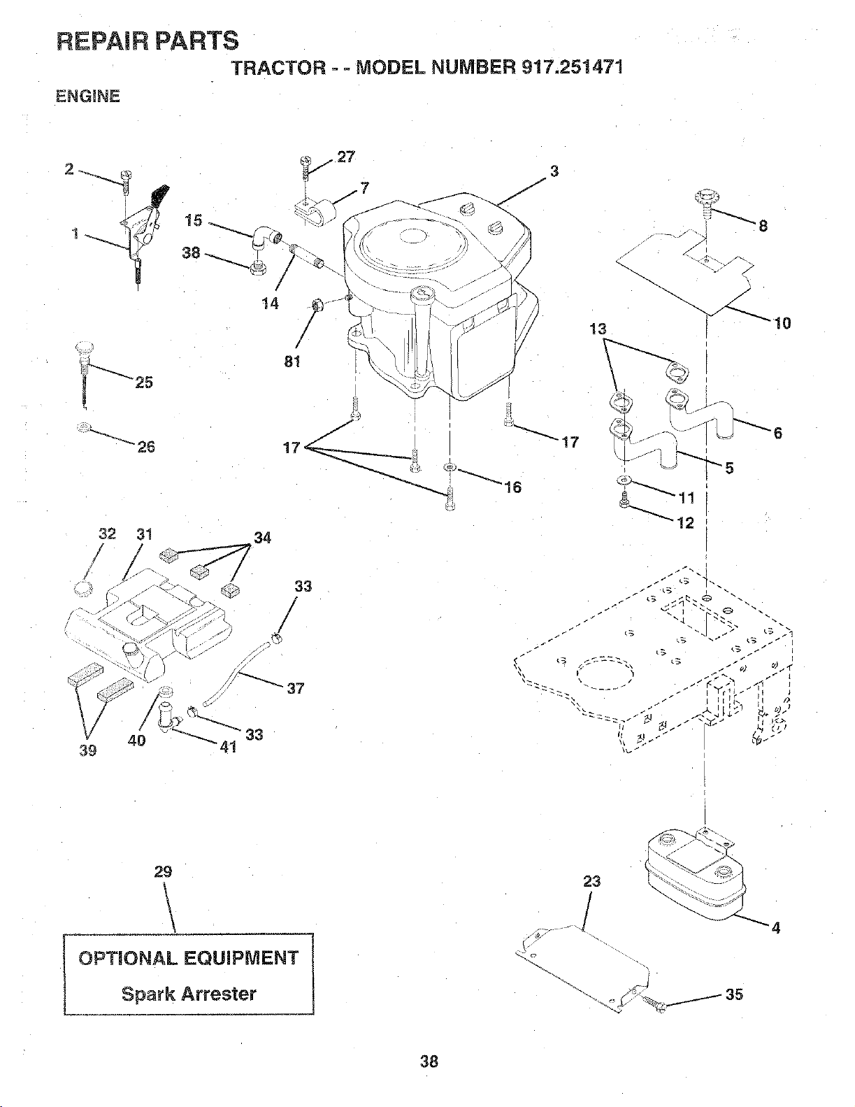
REPAIR PARTS
TRACTOR - - MODEL NUMBER 917.251471
ENGINE
/
14
81
32
3! 34
33
/
40 33
39
13
S
x_ 10
29
OPTIONAL EQUIPMENT
Spark Attester
23
_4
38
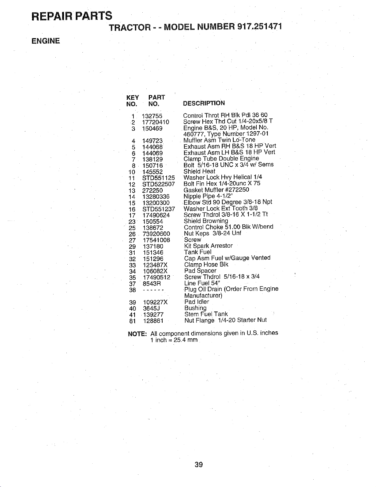
REPAIR PARTS
TRACTOR =- MODEL NUMBER 917.251471
ENGINE
KEY PART
NO. NO. DESCRIPTION
1
2
3
132755
17720410
150469
4 149723
5 144068
6 144069
7 138129
8 150716
10 145552
11 STD551125
12 STD522507
13 272250
14 13280336
15 13200300
16 STD551237
17 17490624
23 150554
25 138672
26 73920600
27 17541008
29 137180
31 151346
32 151296
33 123487X
34 106082X
35 17490512
37 8543R
38 ......
39 109227X
4O 3845J
41 139277
81 128861
Control Throt RH BIk Pdl 36 60
Screw Hex Thd Cut 1_4-20x5/8 T
Engine B&S, 20 HP. Model No
460777. Type Number 1297-01
Muffler Asm Twin Lo-Tone
Exhaust Asm RH B&S 18 HP Vert
Exhaust Asm LH B&S 18 HP Verl
Clamp Tube Double Engine
Bolt 5/16-18 UNC x 3/4 w/Seres
Shield Heat
Washer Lock Hvy Helical 1/4
Bolt Fin Hex 1!4-2Ounc X 75
Gasket Muffler #272250
Nipple Pipe 4- t/2"
Elbow Std 90 Degree 3/8-18 Not
Washer Lock Ext Tooth 3/8
Screw Thdrol 3/8-16 X 1-1/2 Tt
Shield Browning
Control Choke 51.00 BIk W/bend
Nut Kees 3/8-24 Unf
Screw
Kit SparK Arrestor
Tank Fuel
Cap Asm Fuel w/Gauge Vented
Clamp Hose BIk
Pad _pacer
Screw Thdro! 5/16-18 x 3/4
Line Fuel 54"
Plug Oil Drain fOrder From Engine
Manufacturer)
Pad Idler
Bushing
Stem Fuel Tank
Nut Flange 1/4-20 Star[er Nut
NOTE: All component dimensions given in U.S. inches
1 inch = 25.4 mm
39
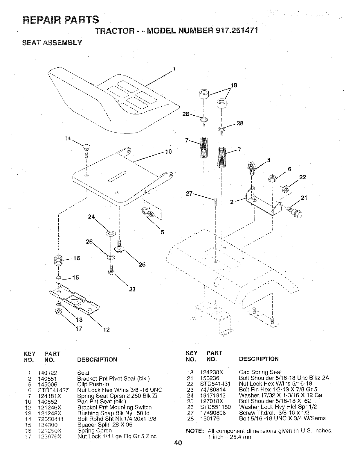
REPAIR PARTS
TRACTOR - - MODEL NUMBER 917.251471
SEAT ASSEMBLY
14..
J
i
116
\
17 "12
\
5
,/
_T _. _-
"b.
_J J
1" . 2_3"
/.
J
s
21
KEY
NO.
2
O
6
7
1£
12
13
14
t5
W
PART
NO.
140122
140551
145006
STD54t437
t24181X
t40552
121246X
121248X
72050411
134300
iP,2qOX
12RgT_X
DESCRIPTION
Seal
BracKet Pnt Pivot Seat (blk)
Clio Push-In
Nut Lock Hex W/Ins 318-16 UNC
Sering Seat Cprsn 2 250 BIk Zi
Pan Pnt Seat (blk)
Bracket Pnt Mounting Switch
Bushing Snap BIk Nyl 50 Id
Bolt Rdhd Sht Nk !/4-20xl-3/8
Spacer Spirt 28 X 96
Spring Cprsn
Nut Lock 1/4 Lge Fig Gr 5 Zinc
40
KEY PART
NO. NO. DESCRIPTION
18 124238X
21 153236
22 STD541431
23 74780814
24 19171912
25 127018X
26 STD551150
27 17490608
28 150176
Cap Spring Seat
Bolt Shoulder 5/16-18 Unc Blkz-2A
Nut Lock Hex W/Ins 5/16-18
Bolt Fin Hex 1/2-13 X 7/8 Gr5
Washer 17/32 X 1-3/16 X 12 Ga
Bolt Shoulder 5/16-18 X 62
Washer Lock Rvy Hlcl Spr 1/2
Screw Thdro! 3/8N6 x 1/2
Bolt 5/16 -18 UNC X 3/4 W/Sems
NOTE: All component dimensions given in U.S. inches.
! inch = 25.4 mm
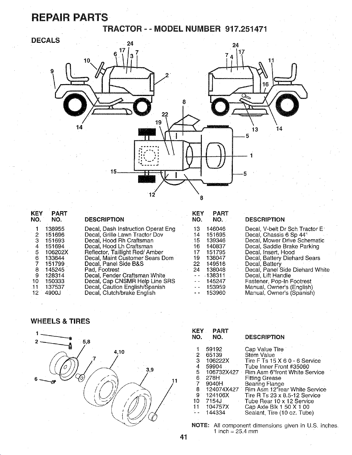
REPAIR PARTS
TRACTOR - - MODEL NUMBER
DECALS 24
9
!0
\
917.251471
24
!7
7
11
/
/
14
15
8
12 k
8
5
1
5
13
\
t4
KEY PART
NO. NO.
1 138955
2 151696
3 151693
4 151694
5 106202X
6 133644
7 151799
8 145245
9 128314
10 150333
11 137537
12 4900J
DESCRIPTION
Decal. Dash Instruction Operat Eng
Decal, Grille Lawn Tractor Dov
Decal. Hood Rh Craftsman
Decal, Hood Lh Craftsman
Reflector, Taillight Red/Amber
Decal. Maint Customer Sears Dom
Decal. Panel Side B&S
Pad. Footrest
Decal. Fender Craftsman White
Decal, Cap CNSMR Help Line SRS
Decal, Caution English/Spanish
Decal. Clutch/brake English
KEY PART
NO. NO,
13 146046
14 151695
15 139346
16 140837
17 151795
19 138047
22 149516
24 138048
-- 138311
-- 145247
-- 153959
-- 153960
DESCRIPTION
Decal. V-belt Dr Sch Tractor E
Decal. Chassis 6 Sp 44"
Decal. Mower Drive Schematic
Decal. Saddle Brake Parking
Decal. Insert, Hood
Decal. Battery Diehard Sears
Decal. Battery
Decal. Panel Side Diehard White
Decal. Lift Handle
Fastener. Pop-In Footrest
Manual Owner's (English_
Manual. Owner's (Spanish)
WHEELS & TIRES
5,8
7
4.10
/
41
KEY PART
NO. NO. DESCRIPTION
1 59192
2 65139
3 106222X
4 59904
5 106732X427
6 278H
7 9040H
8 124074X427
9 124106X
10 7154J
11 104757X
-- 144334
CaD Value Tire
Stem Value
Tire F Ts 15 X 6 0 - 6 Service
Tube Inner Front #35060
Rim Asm 6"front White Service
Fitting Grease
Bearing Flange
Rim Asm 12"rear White Service
Tire R Ts 23 x &5-t2 Service
Tube Rear 10 x 12 Service
CaD Axle B[k 1 50 X 1 00
Sealant, Tire _10 oz. Tube)
NOTE: All component dimensions gfven in U.S. inches.
1 _nch = 25.4 mm
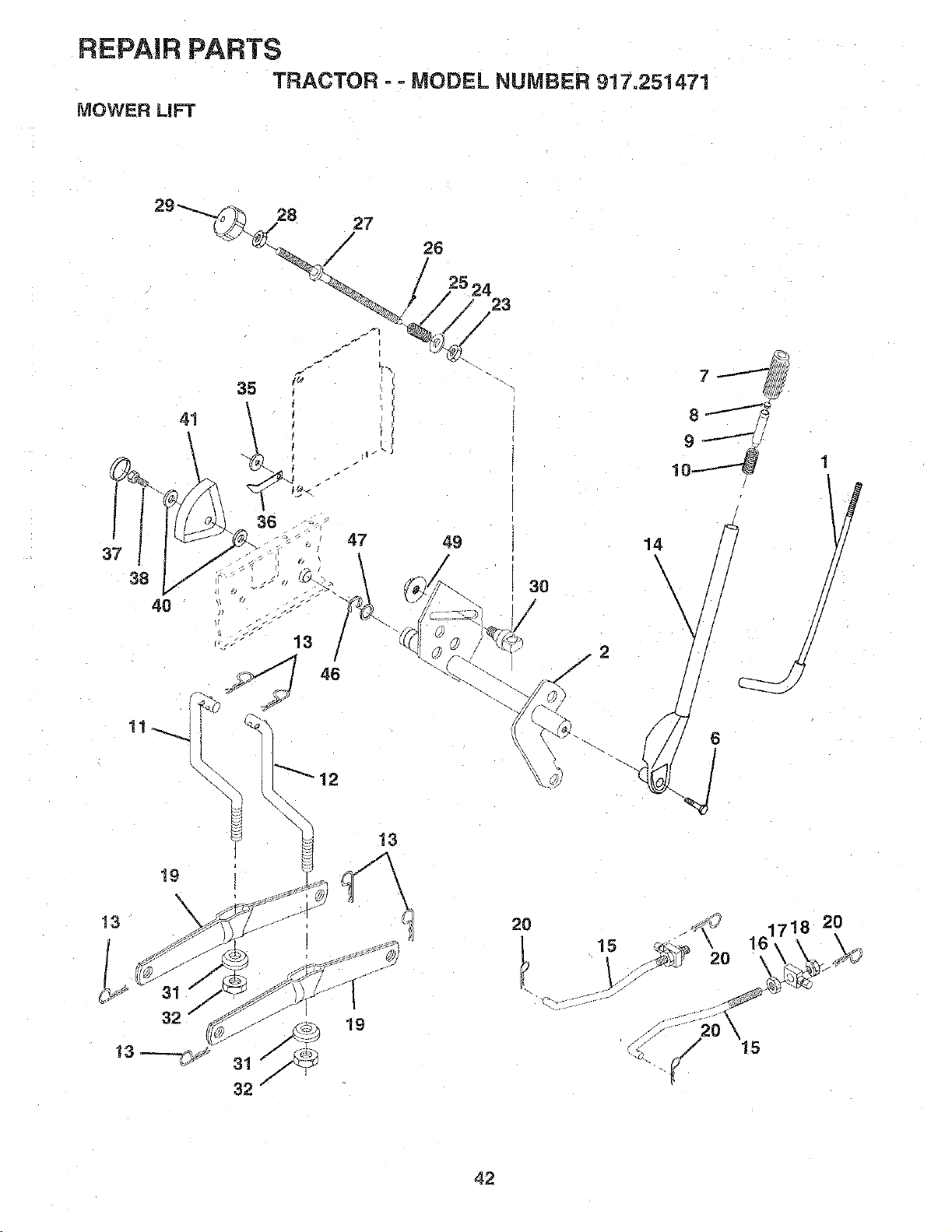
REPAIR PARTS
TRACTOR ==MODEL NUMBER 917o251471
MOWER LiFT
28 27
/
26
38
4O
23
\
13
14
\
\
\
1
!
IJ
2O
c". _-" -
15
42
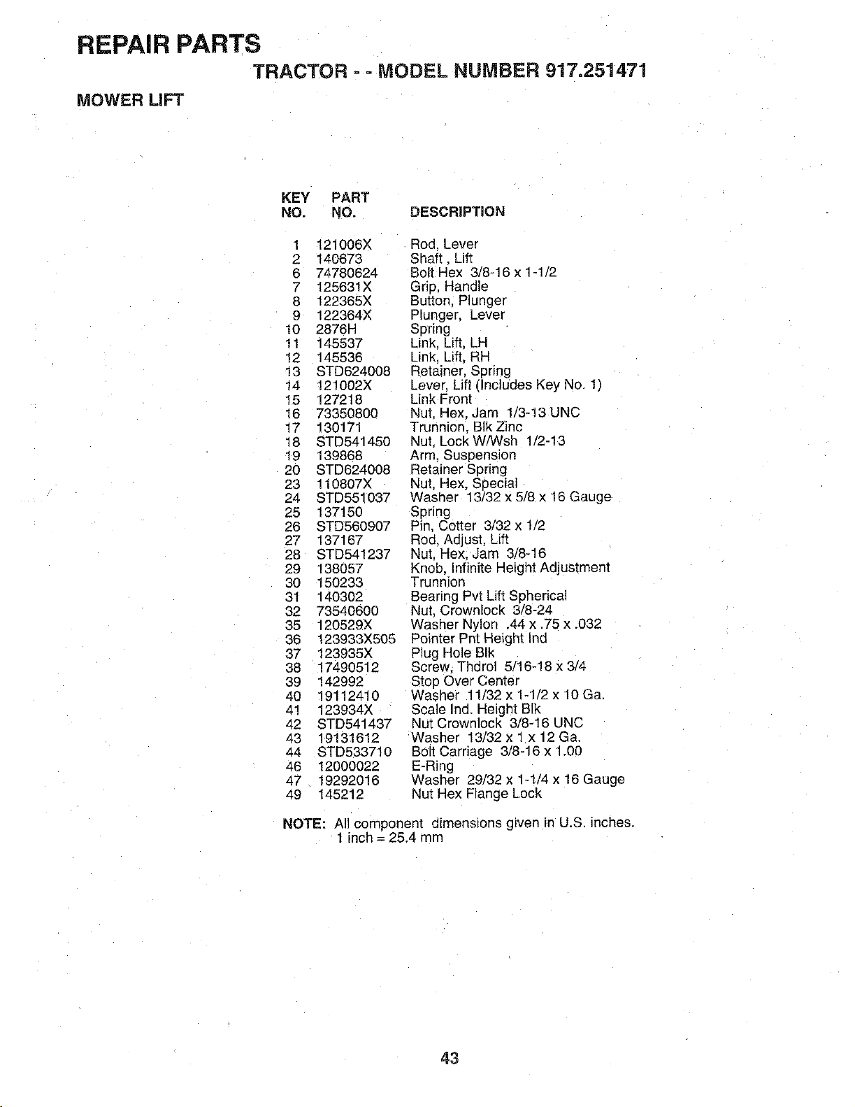
REPAIR PARTS
TRACTOR - - MODEL NUMBER 917.251471
MOWER LIFT
KEY PART
NO. NO. DESCRiPTiON
1 121006X
2 140673
6 74780624
7 125631X
8 122365X
9 122364X
10 2876H
11 145537
12 145536
13 STD624008
14 121002X
15 127218
16 73350800
17 130171
18 STD541450
19 139868
20 STD624008
23 110807X
24 STD551037
25 137150
26 STD560907
27 137167
28 STD541237
29 138057
30 150233
31 140302
32 73540600
35 120529X
36 !23933X505
37 123935X
38 17490512
39 142992
40 19112410
41 123934X
42 STD541437
43 19131612
44 STD533710
46 12000022
47 19292016
49 145212
Rod. Lever
Shaft. Lift
Bolt Hex 3/8-t6 x 1-1/2
Grip, Handle
Sutton. Plunger
Plunger, Lever
Spring
Link. Lift. LH
Link, Lift. RH
Retainer. Spring
Lever. Lift (Includes Key No. 1)
Link Front
Nut Hex. Jam 1/3-13 UNC
Trunnior SIk Zinc
Nut. Lock W/Wsh 1/2-13
Arm. Suspension
Retainer Spring
Nut. Hex, Seecial
Washer 13/32 x 5/8 x 16 Gauge
Spring
Pin. Cotter 3/32 x 1/2
Rod. Adjust. Lift
Nut. Hex. Jam 3/8-16
Knob. infinite Height Adjustment
Trunnion
Searing Pvt Lift Spherical
Nut. Crownlock 3/8-24
Washer Nylon .44 x .75 x .032
Pointer Pnt Height Ind
Plug Hole BIk
Screw. Thdrol 5/16-18 x 3/4
Stop Over Center
Washer 11/32 x 1-1/2 x 10 Ga.
Scale Ind. Height Slk
Nut Crownlock 3/8-16 UNC
Washer 13/32 x 1 x 12 Ga.
Bolt Carriage 3/8-16 x 1.00
E-Ring
Washer 29/32 x 1-t/4 x 16 Gauge
Nut Hex Flange Lock
NOTE: All component dimensions given in U.S, inches.
1 inch = 25.4 mm
43
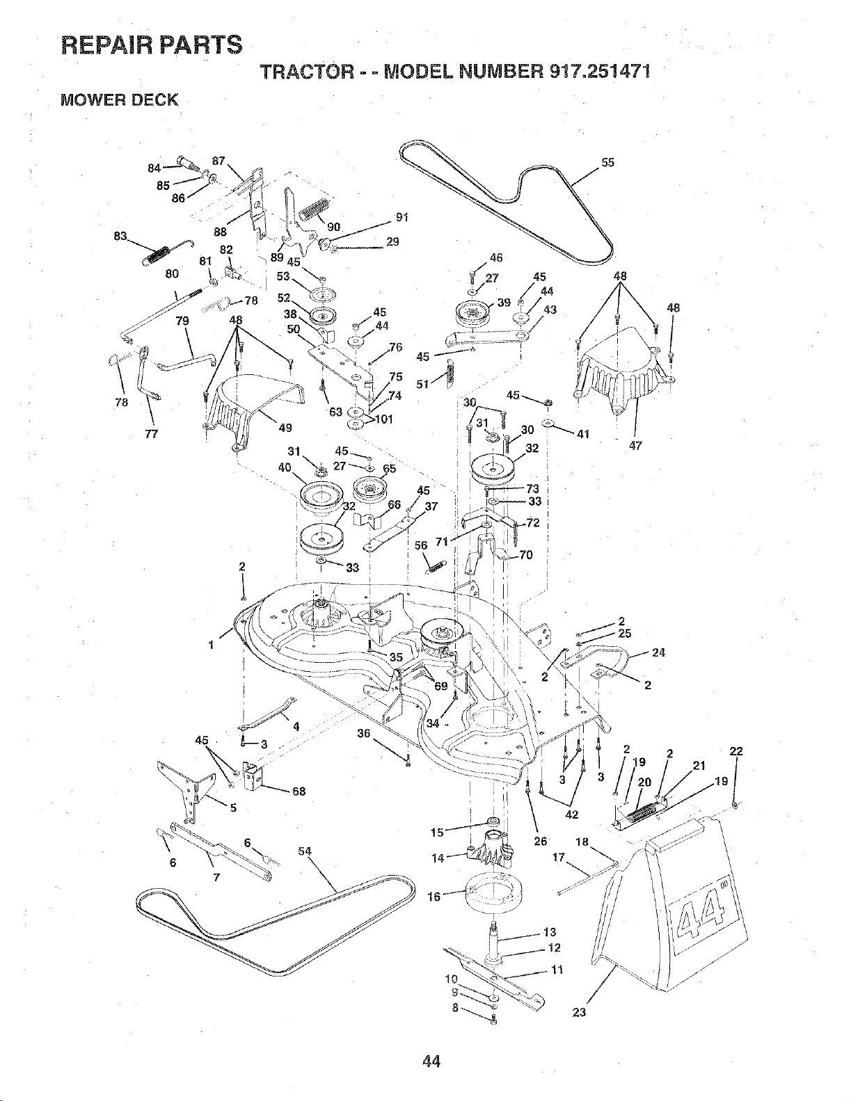
REPAIR PARTS
TRACTOR - ° MODEL NUMBER 917.251471
MOWER DECK
2
/\
1
33
45
q?'_.-72
_::_70
48
j2
47
36
42
\
26 18
17
/
23
48
2
21
22
44
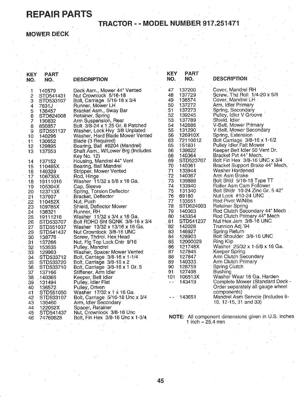
REPAIR PARTS
TRACTOR ==MODEL NUMBER 917.251471
MOWER DECK
KEY PART KEY PART
NO. NO. DESCRIPTION NO. NO. DESCRIPTION
1 140579
2 STD541431
3 STD533107
4 7631J
5 138457
6 STD624008
7 130832
8 850857
9 STD551137
10 140296
11 130652
12 129895
13 137553
14 137152
15 110485X
16 140329
17 106735X
18 19111016
19 105304X
20 123713X
21 137607
22 110452X
23 109785X
24 136321
25 19111216
26 STD533707
27 STD551037
29 STD541437
30 138776
31 137266
32 153536
33 129963
34 STD533712
35 STD533720
36 STD533710
37 137168
38 140365
39 131494
40 136572
41 STD551050
42 STD533107
43 136460
44 122052X
45 STD541437
48 74760628
Deck Asm.. Mower 44" Vented 47 137200
Nut Crewnlock 5/16-18 48 137729
Bolt. Carriage 5/16-18 x 3/4 49 136574
Runner. Mower LH 50 137272
Bracket Asrn.. Sway Bar 51 t37273
Retainer. Spring 52 139245
Arm Suspension, Rear 53 137789
Bolt 3/8-24 x 1.25 Gr. 8 Patched 54 142686
Washer, Lock HW 3/8 Unplated 55 131290
Washer. Hard Blade Mower Vented 56 126910X
Blade f3 Reauired) 63 72110612
Bearing, Ball #6204 (Mandrel) 65 151831
Shaft Asm.. W/Lower Brg (Includes 66 139622
Key No. 12) 68 140364
Housing, Mandrel44" Vent 69 STD523707
Bearing, Ball Mandrel 70 140361
Stripper, Mower Vented 71 133944
Rod. Hinge 72 140367
Washer 11/32x5/8x16Ga. 73 139888
Cap. Sleeve 74 133940
Spring, Torsion Deflector 75 131340
Bracket. Deflector 76 69180
Nut. Push 77 133551
Shield. Deflector Mower 78 STD624003
Runner. RH 79 140363
Washer 11/32 x 3/4 x 16 Ga. 80 143354
Bolt RDHD Sht SQNK 3/8-16 x 3/4 81 STD541237
Washer 13/32 x 13/16 x 16 Ga. 82 142028
Nut Crownlock 3/8-16 UNC 83 146927
Screw. Thdrol. Hex Head 84 128903
Nut. Fig Top Lock Cntr 9/16 85 12000029
Pulley Mandrel 86 121748X
Washer, Spacer Mower Vented 87 127845
Bolt. Carriage 3/8-16 x 1-1/4 88 127847
Bolt. Carriage 3/8-16 x 2 89 140333
Bolt. Carriage 3/8-16 x 1 Gr. 5 90 t28759
Stiffener. Arm idler 91 127498
Keeper, Belt Idler 101 106513X
Pulley, Idler Flat -- 143419
Pulley, Driven
Washer 17/32 x 1x 16 Ga.
Bolt. Carriage 5/16-18 Unc x 3/4 - - 143651
Arm. Idler Secondary
Seacer. Retainer
Nut. Crownlock 3/8-16 Unc
Bolt. Fin Hex 3/8-16 Unc x 1-3/4
Cover. Mandrel RH
Screw Thd Roll 1/4-20 x 5/8
Cover. Mandrel LH
Arm Idler Primary
Spring, Secondary
Pulley, Idler V Groove
Shield idler
V-Belt. Mower Primary
V-Belt. Mower Secondary
Spring, Extension
Bolt Carriage 3/8-16 x 1-1/2
Pulley Idler Falt Mower
Keeper Belt Idler 50 Vent Dr.
Bracket Pvt 44" Mech.
Bolt Fin Hex 3/8-16 UNC x 3/4
Bracket Support Brake 44" Mech.
Washer Hardened
Arm Asm Brake
Bolt Shld 5/16-18 Type TT
Roller Asm Cam Follower
Bolt Shldr 10-24 Zinc Gr. 5 42
Nut Lock #10-24 UNC
Rod Pivot W/Nibs
Retainer Spring
Rod Clutch Secondary 44" Mecl"
Rod Clutch Primary 44" Mech
Nut Hex Jam 3/8-16 UNC
Trunnion Adj. '94
Spring Return
Bolt Shoulder 3/8-18 UNC
Ring Klip
Washer 25/32 x 1-5/8 x 16 Ga
Keeper Spnng
Arm Clutch Secondary
Arm Clutch Primary
Spring Clutch
Bushing
Washer Wear 16 Ga. Harden
Complete Mower qStandard Deck -
Order separately all gauge wheel
comoonentst
Mandrel Asm Servcie flnc]udes 8-
10. 12-15.31 and 331
NOTE: All component dimensions gwen in U.S. inches
1 inch = 25.4 turn
45
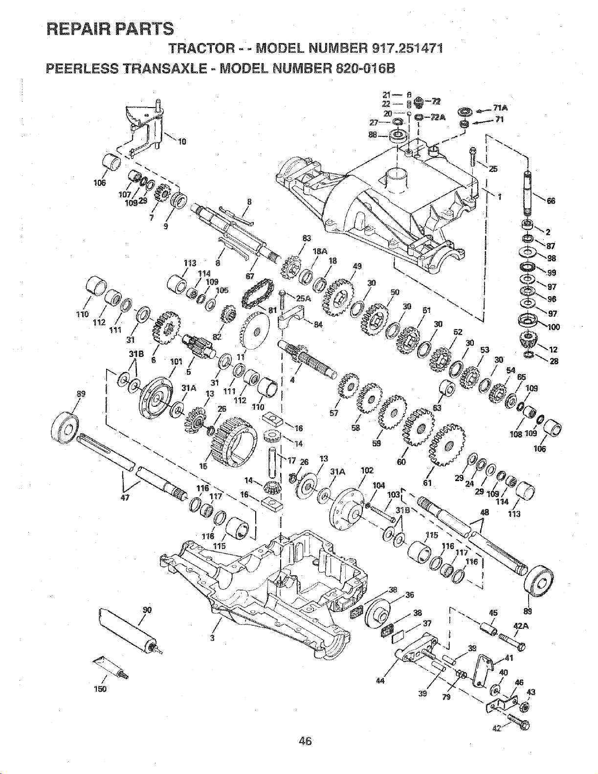
REPAIR PARTS
TRACTOR -- MODEL NUMBER 917.251471
PEERLESS TRANSAXLE - MODEL NUMBER 1t20-0t lib
/
115
/
39 43
46
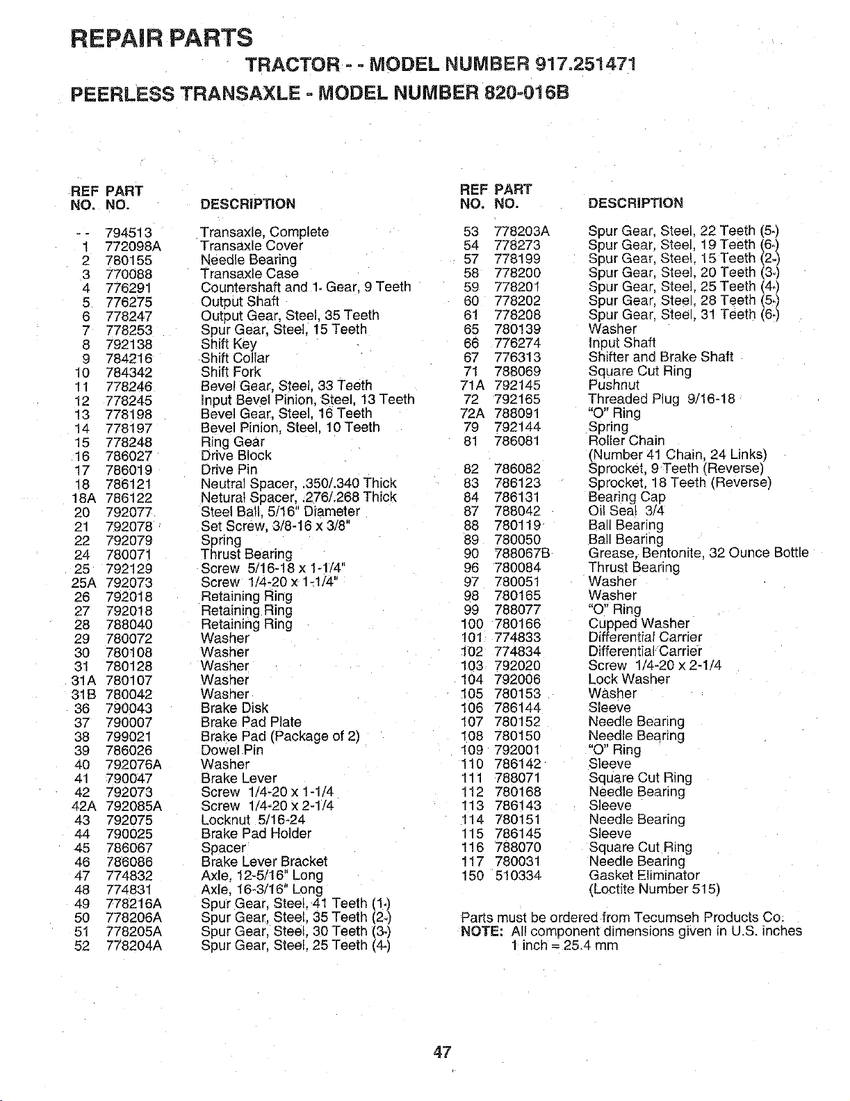
REPAI R PARTS
TRACTOR - =MODEL NUMBER 917.251471
PEERLESS TRANSAXLE o MODEL NUMBER 820=016B
REF PART REF PART
NO, NO. DESCRIPTION NO. NO. DESCRIPTION
-- 794513 Transaxle. Complete 53 778203A
1 772098A Transaxle Cover 54 778273
2 780155 Needle Bearing 57 778199
3 770088 Transax!e Case 58 778200
4 776291 Countershaft and 1,Gear. 9 Teeth 59 778201
5 776275 Output Shaft 60 778202
6 778247 Output Gear. Steel. 35Teeth 61 778208
7 778253 Spur Gear. Steel. 15 Teeth 65 780139
8 792138 Shift Key 66 776274
9 784216 Shift Collar 67 776313
10 784342 Shift Fork 71 788069
11 778246 Beve!Gear. Steel, 33 Teeth 71A 792145
12 778245 input Bevel Pinion. Steel. 13 Teeth 72 792165
13 778198 Bevel Gear. Steel. 16 Teeth 72A 788091
14 778197 Bevel Pin!or. Steel. 10Teeth 79 792144
15 778248 Ring Gear 81 786081
16 786027 Drive Block
17 786019 Drive Pin 82 786082
18 786121 Neutral Spacer, .350/.340 Thick 83 786123
18A 786122 Neturat Spacer..276/.268 Thick 84 786131
20 792077 Steel Ball. 5/16" Diameter 87 788042
21 792078 Set Screw. 3/8-16 x 3/8" 88 780119
22 792079 Spring 89 780050
24 780071 Thrust Bearing 90 788067B
25 792129 Screw 5/18-18 x 1-1/4" 96 780084
25A 792073 Screw 1/4-20 x 1-1/4" 97 780051
26 792018 Retaining Ring 98 780165
27 7920t8 Retaining Ring 99 788077
28 788040 Retaining Ring 100 780166
29 780072 Washer 101 774833
30 780108 Washer 102 774834
31 780128 Washer 103 792020
31A 780107 Washer 104 792006
31B 780042 Washer 105 780153
36 790043 Brake Disk 106 786144
37 790007 Brake Pa_ Plate 107 780152
38 799021 Brake Pad (Package of 2) 108 780150
39 786026 Dowel Pin !09 792001
40 792076,_ Washer 110 786142
41 790047 Brake Lever 111 788071
42 792073 Screw 1/4-20x1-1/4 112 780168
42A 792085A Screw 1/4-20x2-1/4 113 786143
43 792075 Locknut 5/16-24 114 780151
44 790025 Brake Pad Holder 115 786145
45 786067 Spacer 116 788070
46 786086 Brake Lever Bracket 117 780031
47 774832 Axle. 12-5/16" Long 150 510334
48 774831 Axle, 16-3/16" Long
49 778216A Spur Gear, Steel. 41 Teeth (1.)
50 778206A Spur Gear, Steel, 35 Teeth (2.)
51 778205A Spur Gear. Steel, 30 Teeth (3.)
52 778204A Sour Gear. Steel. 25 Teeth (4.)
Spur Gear. Steel. 22 Teeth (5.)
Spur Gear. Steel. 19 Teeth (6.)
Spur Gear. Steel. 15 Teeth (2-)
Spur Gear. Steel. 20 Teeth (3°)
Spur Gear, Steel. 25 Teeth (4.)
Spur Gear. Steel. 28 Teeth (5.)
Spur Gear. Steel. 31 Teeth (64
Washer
Input Shaft
Shifter and Brake Shaft
Square Cut Ring
Pushnut
Threaded Plug 9/16-t8
"O" Ring
Spring
Roller Chain
(Number 41 Chair 24 Links)
Sprocket, 9 Teeth Reverse)
Sprocket. 18 Teeth (Reverse)
Bearing Cap
Oil Seat 3/4
Ball Bearing
Ball Bearing
Grease. Bentonite. 32 Ounce Bottle
Thrust Bearing
Washer
Washer
"O" Ring
Cupped Washer
Differential Career
Differential Carrier
Screw 1/4-20 x 2-1/4
Lock Washer
Washer
Sleeve
Needle Bearing
Needle Bearing
"O" Ring
Sleeve
Sauare Cut Ring
Needle Beating
Sleeve
Needle Bearing
Sleeve
Square Cut Ring
Needle Bearing
Gasket Eliminator
(Loctite Number 515)
Parts must be ordered from Tecumseh Products Co.
NOTE; All component dimensions given in U.S. inches
t inch = 2&4 mm
47
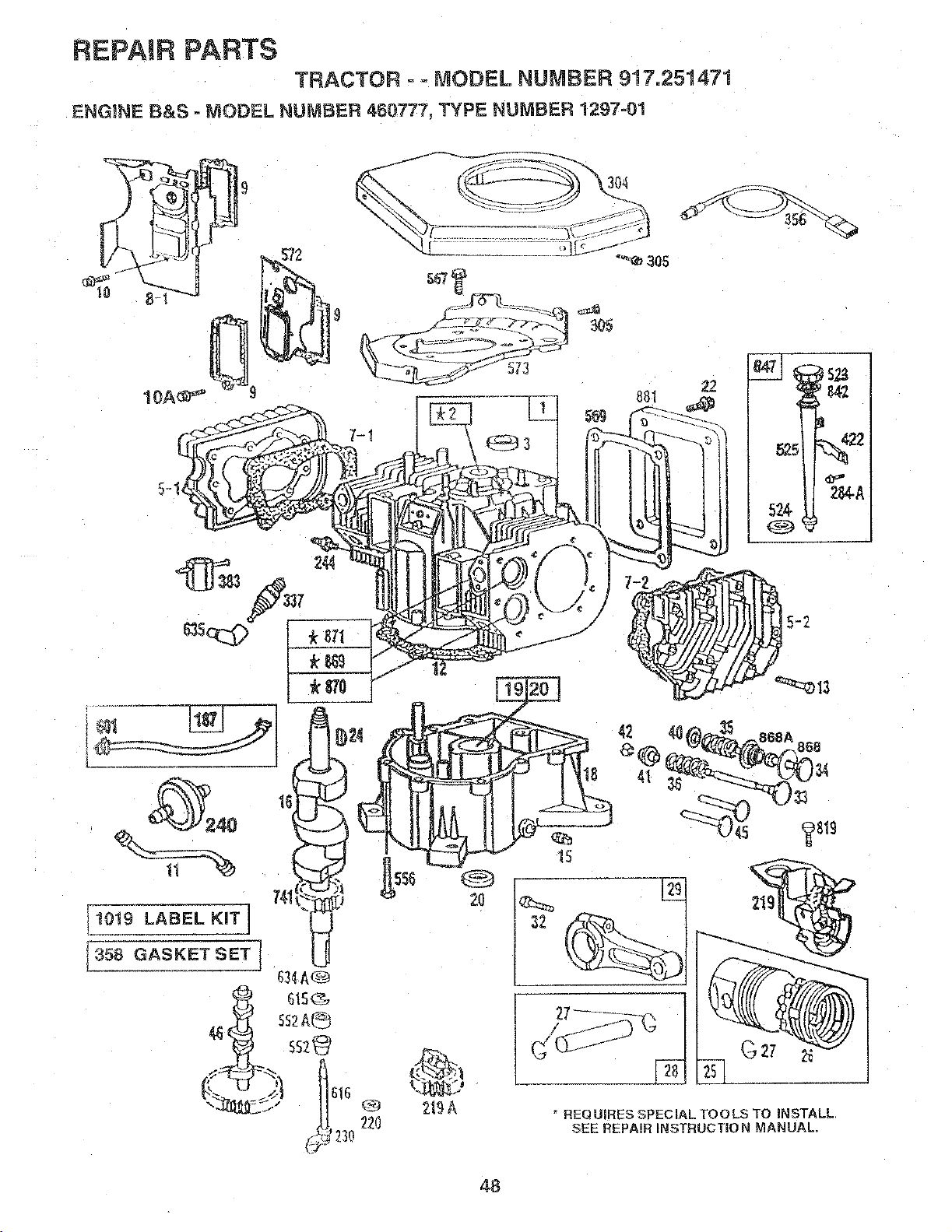
REPAIR PARTS
TRACTOR - - MODEL NUMBER 917o251471
ENG)NE B&S - MODEL NUMBER 460777, TYPE NUMBER 1297-01
22O
21_A
48
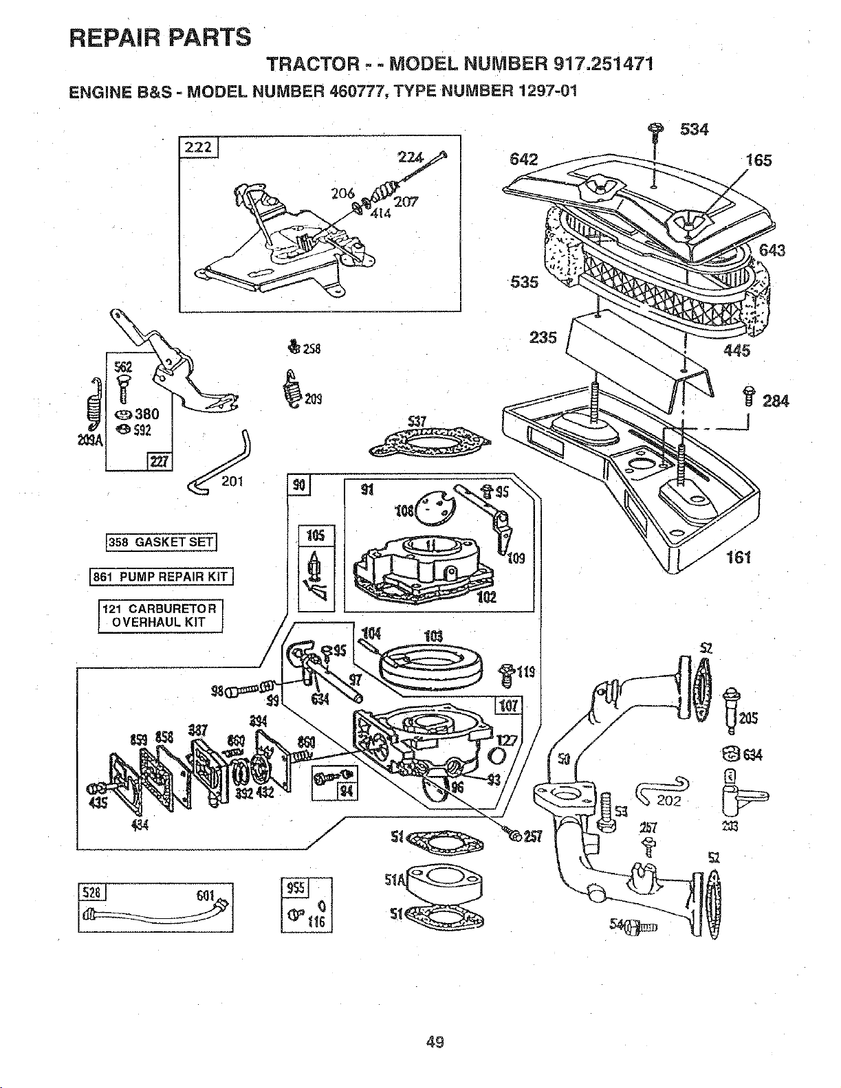
REPAIR PARTS
TRACTOR - =MODEL NUMBER 917.251471
ENGINE B&S - MODEL NUMBER 460777, TYPE NUMBER 1297-01
(358GASKET SET]
[861PUMP REPAIR KITI
121 CARBURETOR
OVERHAUL KIT
535
235
@
534
_Z
165
/
284
49
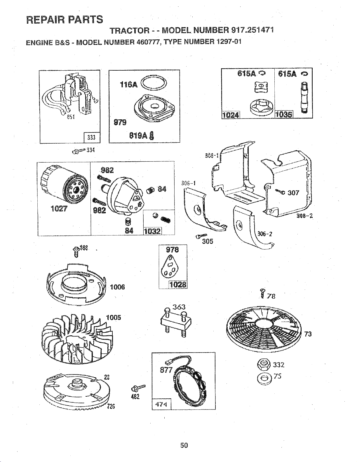
REPAIR PARTS
TRACTOR - - MODEL NUMBER 917.25t 4'71
ENGINE B&S - MODEL NUMBER 460777, TYPE NUMBER 1297-01
334
t16A O
81_Ag
%82
_06-d
978
305
482
615A '_
G
_ 2"8
r 73
5o
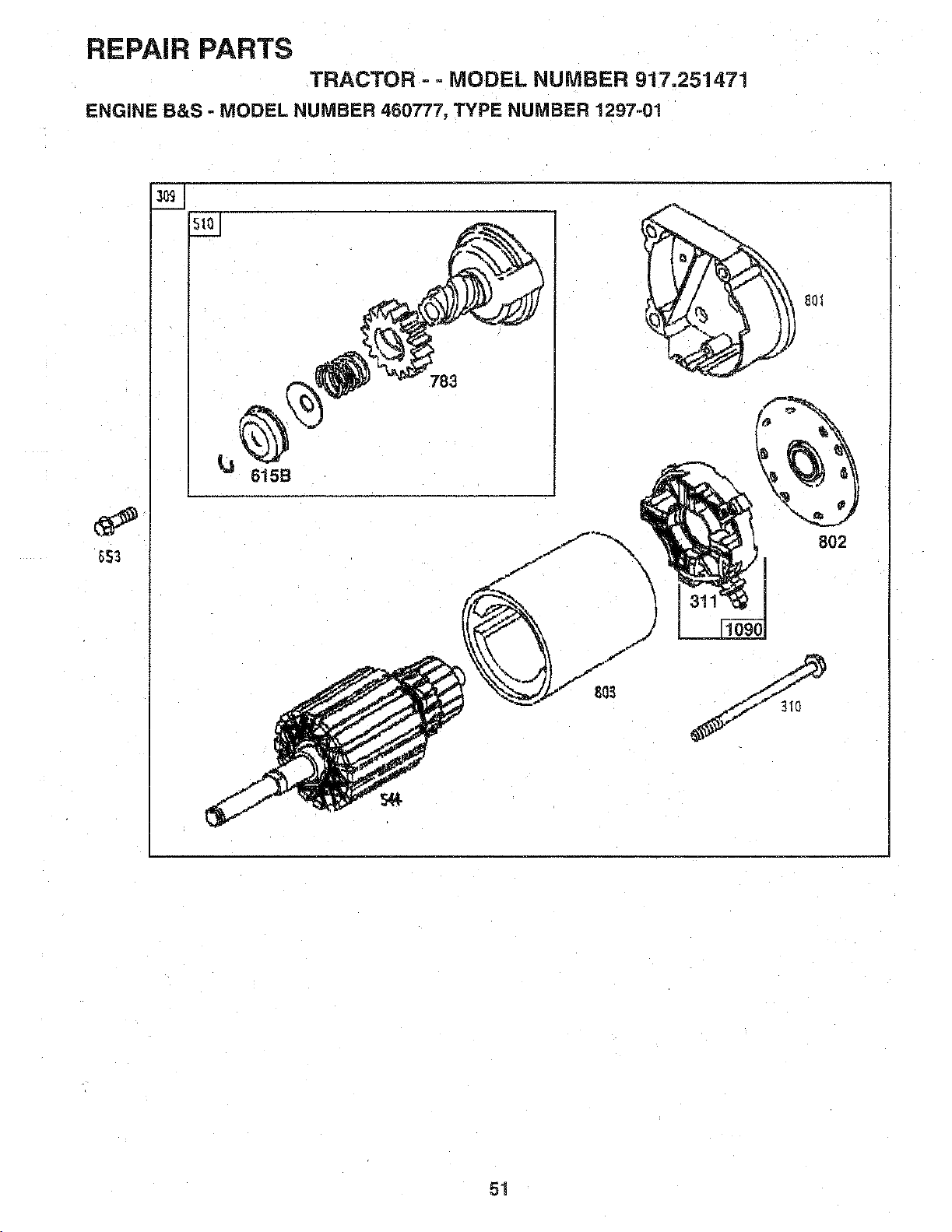
REPAIR PARTS
TRACTOR - _MODEL NUMBER 917.2514,71
ENGINE B&S = MODEL NUMBER 450777, TYPE NUMBER 1297-01
783
615B
fJ
j_
f
8_
\
\
k
f
801
802
51
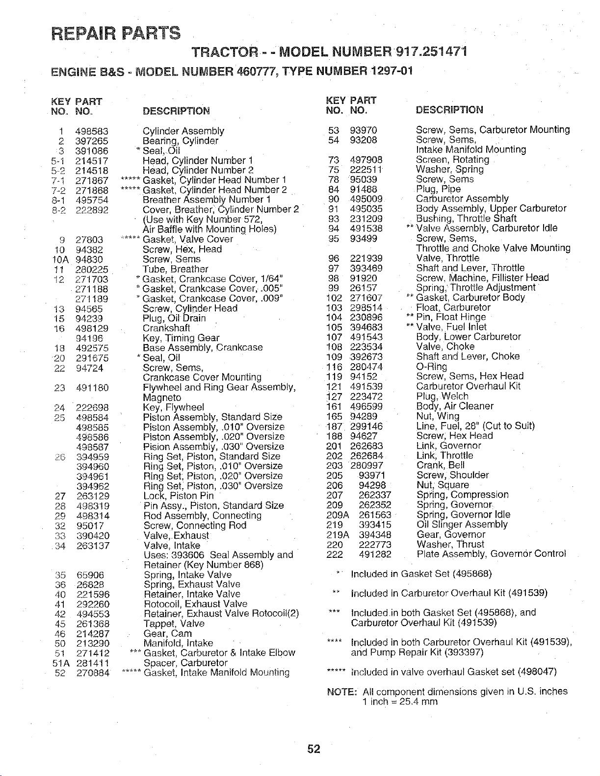
REPAIR PARTS
TRACTOR o- MODEL NUMBER 917.251471
ENGINE 8&S _ MODEL NUMBER 460777, TYPE NUMBER 1297-01
KEY PART KEY PART
NO. NO° DESCRIPTION NO, NO. DESCRiPTiON
1 498583
2 397265
3 391086
5_1 214517
5-2 214518
7_1 271867
7-2 271868
8-1 495754
_-2 222892
9 27803
i0 94382
I0A 94830
11 280225
12 271703
271188
271189
13 94565
lb 94239
16 498129
94196
18 492575
20 291675
22 94724
23 491180
24 222698
26 4.98584
498585
498586
498587
J 394959
394960
394961
394962
27 263129
28 498319
29 498314
32 95017
_3 390420
;4 263137
35 65906
36 26828
¢0 221596
41 292260
42 494553
45 261388
46 214287
50 213290
51 271412
51A 281411
52 270884
Cylinder Assembly 53 93970
Bearing, Cylinder 54 93208
*Seai Oil
Head. Cylinder Number 1 73 497908
Head. Cylinder Number 2 75 222511
..... Gasket. Cylinder Head Number 1 78 95039
..... Gasket. Cylinder Head Number 2 84 91488
Breather Assembly Number 1 90 495009
Cover, Brea[her, Cylinder Number 2 91 495035
rUse with Key Number 572, 93 231209
Air Baffle with Mounting Holes) 94 491538
...... Gasket. Valve Cover 95 93499
Screw, Flex. Head
Screw Seres 96 221939
Tube. Breather 97 393469
* Gasket. Crankcase Coveq 1/64" 98 91920
* Gasket. Crankcase Cover..005 99 26!57
"Gasket. Crankcase Cover..009" 102 271607
Screw. Cylinder Head 183 298514
Plug, Oil Drain 104 230896
Crankshaft 105 394683
Key, Timing Gear 107 491543
Bas_ Assembly, CranKcase 108 223534
*Sea Oil 109 392673
Screw Seres, 116 280474
Crankcase Cover Mounting 119 94152
Fiywheel and Ring Gear Assembly, 121 491539
Magne[o 127 223472
Key, Flywheel 161 496599
Piston Assembly, Standard Size 165 94289
Piston Assembly, .010" Oversize 187 299146
Piston Assembly, .020" Oversize 188 94627
Pision Assembly, .030" Oversize 201 262683
Ring Set. Piston. Standard Size 202 262684
Ring Set. Piston..010" Oversize 203 280997
Ring Set. Piston..020" Oversize 205 93971
Ring Set, Piston..030" Oversize 206 94298
Lock Piston Pin 207 262337
Pin Assy.. Piston. Standard Size 209 262352
Rod Assembly, Connecting 209A 261563
Screw. Connecting Rod 219 393415
Valve. Exhaust 219A 394348
Valve ntake 220 222773
Uses: 393606 Seal Assembly ann 222 491282
Retainer (Key Number 868)
Spring, Intake Valve
Spring, Exhaust Valve
Retainer Intake Valve
Rotocoi Exhaust Valve
Retainer. Exhaust Valve Rotocoih'2)
Tappet Valve
Gear. Cam
Manifold Intake
_-_Gasket Carburetor & Intake Elbow
Spacer. Carburetor
..... Gasket. Intake Manifold MoLmting
Screw. Seres. Carburetor Mounting
Screw. Seres.
Intake Manifold Mounting
Screen. Rotating
Washer Spring
Screw. Seres
Plug, Pipe
Carburetor Assembly
Body Assembly, Upper Carburetor
Bushing, Throttle Shaft
** Valve Assembly, Carburetor Idle
Screw. Sems.
Throttle and Choke Valve Mounting
Valve Throttle
Shaft and Lever Throttle
Screw Machine Fillister Head
Spring, Throttle Adjustment
_*Gasket Carburetor Body
Float Carburetor
3, Pin Float Hinge
** Valve. Fuel Inlet
Body Lower Carburetor
Valve Choke
Shaft and Lever. Choke
Q-Ring
Screw. Sems. Hex Head
Carburetor Overhau Kit
Plug, Welch
Body, Air Cleaner
Nut. Wing
Line Fuel. 28' Cut to Suit)
Screw. Hex Heac
Link. Governor
Link. Throttle
Crank Bell
Screw. Shoulder
Nut. Suuare
Spring, Compression
Spring: Governor
Spring, Governor Idle
Oil Slinger Assembly
Gear Governor
Washer. Thrusl
Plate Assembly, Governor Control
Included m Gasket Set (495868)
included in Carburetor Overhaul Kit (491539)
"-" Included in both Gasket Set 1495868L ann
Carburetor Overhaul Kit (491539)
.... Included in both Carburetor Overhaul Kit (491539)
ana Pump Reoair Kit (393397)
..... Included in valve overhaul Gasket set _498047)
NOTE: All componem aimenslons gwen JnU.S. inches
" inch = 25.4 mm
52
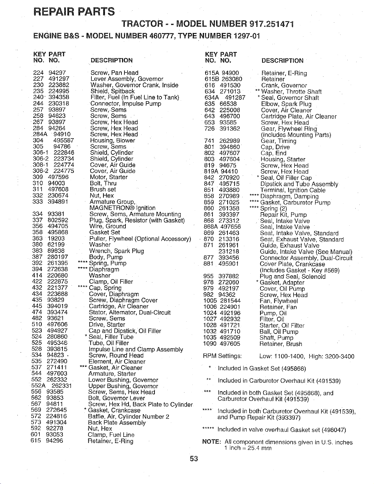
REPAIR PARTS
TRACTOR -- MODEL NUMBER 917.251471
ENGINE B&S - MODEL NUMBER 460777, TYPE NUMBER 1297-01
KEY PART KEY PART
NO. NO. DESCRIP'RON NO. NO.
224 94297
227 491297
230 223882
235 224995
240 394358
244 230318
257 93897
258 94623
267 93897
284 94264
284A 94910
304 495587
305 94786
306-1 222846
306-2 223734
308-1 224774
308-2 224775
309 497596
310 94003
311 497608
332 230674
333 394891
334 93381
337 802592
356 494705
358 495868
363 19203
380 62199
383 89838
387 280197
392 261395
394 272638
414 220680
422 222875
432 221377
434 223688
435 93829
445 394019
474 393474
482 93621
510 497606
523 494927
524 280860
528 495348
528 393815
534 94823 -
535 272490
537 271411
544 497603
552 262332
552A 262331
556 93585
562 93853
567 94811
569 272645
572 224816
573 491304
592 92278
601 93053
615 94296
Screw. Pan Head
Lever Assembly, Governor
Washer. Governor Crank. Inside
Shield. Spitback
Filter, Fuel (In Fuel Line to Tank)
Connector. Impulse Pump
Screw. Seres
Screw. Sems
Screw Hex Head
Screw. Hex Head
Screw. Hex Head
Housing, Blower
Screw. Sems
Shield. Cylinder
Shield. Cylinder
Cover. Air Guide
Cover. Air Guide
Motor, Starter
Bolt. Thru
Brush set
Nut, Hex
Armature Group,
MAGNETRON® Ignition
Screw, Seres. Armature Mounting
Plug, Spark. Resistor Iwith Gasket/
Wire. Ground
Gasket Set
Puller. Flywheel (Optional Accessory /
Washer
Wrench. Spark Plug
Body, Pump
.... Spring, Pump
.... Diaphragm
Washer
Clamp. Oil Filler
.... CaD. Spring
Cover. Diaphragm
Screw, Diaphragm Cover
Cartridge. Air Cleaner
Stator. Alternator, Dual-Circuit
Screw. Sems
Drive Starter
Cap and Diestick. Oil Filler
* Sea]. Filler Tube
Tube. Oil Filler
impulse Line and Clamp Assembly
Screw, Round Head
Element. Air Cleaner
""" Gasket. Air Cleaner
Armature. Starter
Lower Bushing, Governor
Upper Bushing, Governor
Screw, Sems, Hex Head
Bolt, Governor Lever
Screw. Hex Hd. Back Plate to Cylinder
"Gasket, Crankcase
Baffle. Air. Cylinder Number 2
Back Plate Assembly
Nut. Hex
Clame. Fuel Line
Retainer. E-Ring
53
DESCRiPTiON
615A 94900
615B 263080
616 491530
634 271013
634A 491287
635 66538
642 225008
643 496700
653 93585
726 391362
74! 262989
801 394860
802 497607
803 497604
819 94675
819A 94410
842 270920
847 495715
851 493880
858 270989
859 271025
860 261358
861 393397
868 273312
868A 497656
869 261463
870 213316
871 261961
231218
877 393456
881 495901
955 397882
978 272060
979 492197
982 94362
1005 281544
1006 224901
102_ 492196
1027 492932
1028 491721
1032 491710
1035 492509
1090 497605
Retainer. E-Ring
Retainer
Crank, Governor
** Washer. Throtte Shaft
* Seal. Governor Shaft
Elbow. Spark Plug
Cover. Air Cleaner
Cartridge Plate. Air Cleaner
Screw. Hex Read
Gear. Flywheel Ring
tlncludes Mounting Parts_
Gear. Timing
Cap, Drive
Cap, End
Housing, Starter
Screw. Hex Head
Screw Hex Head
- Seal. Oil Filler Cap
Dipstick and Tube Assembly
Terminal. Ignition Cable
....Diaphragm, Damping
.... Gasket. Carburetor Pump
.... Spring (2)
Repair Kit. Pumo
Sea Intake Valve
Seal Intake Valve
Seat. Intake Valve. Standard
Seat, Exhaust Valve. Standard
Guide. Exhaust Valve
Guide. Intake Valve/See Manual;
Connector Assembly, Dual-Circuit
Cover Plate. Crankcase
dncludes Gasket - Key #569/
Plug and Seal, Solenoid
* Gasket. Adapter
Cover. Oil Pump
Screw, Hex Head
Fan Flywheel
Retainer Fan
PumP. Oil
Filter. Oil
Starter. Oil Filter
Ball, Oil Pump
Shaft, Pump
Retainer. Brush
RPM Settings: Low: 1100-1400. High: 3200-3400
Included in Gasket Set 14958681
"" Included in Carburetor Overhaul Kit [491539)
"** Included in both Gasket Set (495868), and
Carburetor Overhaul Kil (491539)
.... Included in both Carburetor Overhaul Kit 149t539L
and Pump Repair Kit (393397)
..... Included ir valve overhaul Gasket set (498047)
NOTE: All component dimensions g ven in U.S. Inches
1 inch = 254 mm

SERVICE NOTES
54

SUGGESTED GUIDE FOR SIGHTING SLOPES FOR SAFE OPERATION
I ""
SIGHTING
GUIDE
ONLY RIDE UP AND DOWN HILL,
NOT ACROSS HILL
SIGHT AND HOLD THiS LEVEL WITH
SKY LINE OR TREE.
15 ° MAX.
!
Operate your Tractor up and down the face of slopes (not
greater than 15°), never across the face. Make turns gradu-
J
ally to prevent tipping or loss of control. Exercise extreme
caution when changing direction on slopes.

OWNER'S
MANUAL
MODEL NO.
917.251471
IF YOU NEED
REPAIR SERVICE
OR PARTS:
FOR REPAIR SERVICE, CALL
THIS TOLL FREE NUMBER:
1-800-4-REPAIR
(1-600-473-7247)
FOR REPLACEMENT PARTS
INFORMATION AND
ORDERING, CALL THIS
TOLL FREE NUMBER:
1-800-FON-PART
(1-800-366-7278)
FOR CONSUMER ASSISTANCE
HOT LINE, CALL THIS
TOLL FREE NUMBER:
1-800-659-5917
£RAFTSMI:IN®
20.0 HP
ELECTRIC START
44" MOWER
6 SPEED TRANSAXLE
GARDEN TRACTOR
Each tractor has its own model number. Each engine has
its own model number.
The model number for your tractor will be found on the
model plate located under the seat.
The model number for your engine will be found on the
blower housing of the engine.
All parts listed herein may be ordered from any Sears,
Roebuck and Co. Service Center/Department and most Re-
tail Stores.
WHEN ORDERING REPAIR PARTS, ALWAYS GIVE THE
FOLLOWING INFORMATION:
• PRODUCT- TRACTOR
• MODEL NUMBER - 9!7.251471
• ENGINE MODEL NO. - 460777, TYPE NO. 1297-01
• PART NUMBER
• PART DESCRIPTION
Your Sears merchandise has added value when you
consider Sears has service units nationwide staffed with
Sears trained technicians.., professional technicians
specifically trained to insure that we meet our pledge to
you, we service what we sell.
153959 Rev.1 02.05.96 RH/KFSW
Printed in U.S.A.


