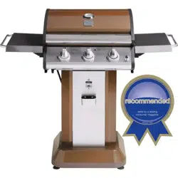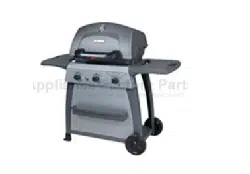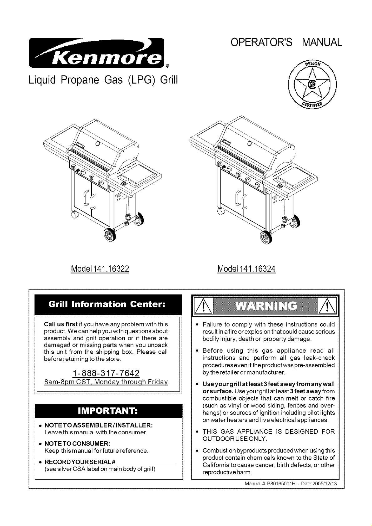
Liquid Propane Gas
OPERATOR'S MANUAL
(LPG)
Grill
Model 141.16322 Model141.16324
Call us first if you have any problem with this
product. We can help you with questions about
assembly and grill operation or if there are
damaged or missing parts when you unpack
this unit from the shipping box. Please call
before returning to the store.
1-888-317-7642
8am-8pm CST, Monday throuqh Friday
• NOTE TO ASSEMBLER/INSTALLER:
Leave this manual with the consumer.
• NOTETO CONSUMER:
Keep this manual forfuture reference.
• RECORDYOURSERIAL#
(see silver CSA label on main body of grill)
Failure to comply with these instructions could
result in afire or explosion that could cause serious
bodily injury, death or property damage.
Before using this gas appliance read all
instructions and perform all gas leak-check
procedures even if the product was pre-assembled
by the retailer or manufacturer.
Use you rgrill at least 3 feet away fro m any wall
orsurface. Use you rgrill at Ieast 3 feet away from
combustible objects that can melt or catch fire
(such as vinyl or wood siding, fences and over-
hangs) or sources of ignition including pilot lights
on water heaters and live electrical appliances.
THIS GAS APPLIANCE IS DESIGNED FOR
OUTDOOR USE ONLY.
Combustion byproducts produced when using this
product contain chemicals known to the State of
California to cause cancer, birth defects, or other
reproductive harm.
Manual # P80165001H - Date:2005/12/13
Primary Safety Warnings ........................... 1-3
Warranty Terms and Conditions .................. 2
Pre-Assembly Instructions .............................. 3
Part Diagrams and Lists .......................... 4-9
Assembly Instructions ............................. 10-16
LP Gas Tank Installation ...................... 17-19
Use & Care Instructions:
• Lighting Instructions ................................. 20
• Troubleshooting .......................................... 21
Cleaning and Maintenance ..................... 22-23
Cooking Guide ........................................ A1-A2
Frequently Asked Questions ................ A3-A4
IF YOU SMELL GAS:
1. Shut off gas to the appliance.
2 Extinguish any open flame.
3. Open lid.
4. If odor continues, keep away from
the appliance and immediately call
your gas supplier or your fire
department.
Leaking gas may cause a fire or
explosion which could result in property
damage, personal injury or death.
1. Do not store spare LP cylinder
within 10 feet (3m) of this appliance.
2. Do not store or use gasoline or
other flammable liquids and
vapors within 25 feet (8m) of this
appliance.
3. When cooking with oil/grease, do
not allow the oil/grease to get
hotter than 350°F (117°C).
4. Do not leave oil/grease unattended.
One-Year Full Warranty on Kenmore Grill
If this grill fails due to a defect in material or work-
manship within one year from the date of purchase,
call 1-800-4-MY-HOME ®to arrange for free repair (or
replacement if repair proves impossible).
Additional Limited Warranty on Specific Grill
Parts
From the date of purchase for the time
periods listed below, the following specific grill
parts will be supplied free of charge if they
fail to meet the conditions described. After the
first year from the date of purchase, you pay
for labor if you wish to have them installed.
• Lid Side Panels - Lifetime, no defects in material
or workmanship; 1 year, no paint loss.
• Stainless Steel Parts - 5 years (except Stainless
Steel Tube Burners - 10 years), no rust-through
• Porcelain coated parts - 3 years, no rust-through
• Cooking grids - 3 years, no rust-through
• Powder coated parts - 2 years, no rust-through
• Savor Plates - 2 years, no rust-through
All warranty coverage excludes ignitor batteries and
grill paint loss (except as specified above) or rusting
(except rust-through as specified above), which are
either expendable parts that can wear out from nor-
mal use in less than a year, or are conditions that
can be the result of normal use, accident or improper
maintenance.
All warranty coverage is void if this grill is
ever used for commercial or rental purposes.
All warrranty coverage applies only if this grill
is used in the country where purchased.
This warranty gives you specific legal rights,
and you may have other rights which vary
from state to state.
Sears, Roebuck and Co., Dept. 817WA,
Hoffman Estates, IL 60179 U.S.A.
© Sears, Roebuck and Co.
Grill Installation Codes
The installation must conform with local codes or, in
the absence of local codes, with either the National
Fuel Gas Code, ANSI Z223.1/NFPA 54, or CAN/CGA-
B149.1, Natural Gas and Propane Installation Code.
Failure to comply with these instructions could
result in a fire or explosion that could cause
serious bodily injury, death or property damage.
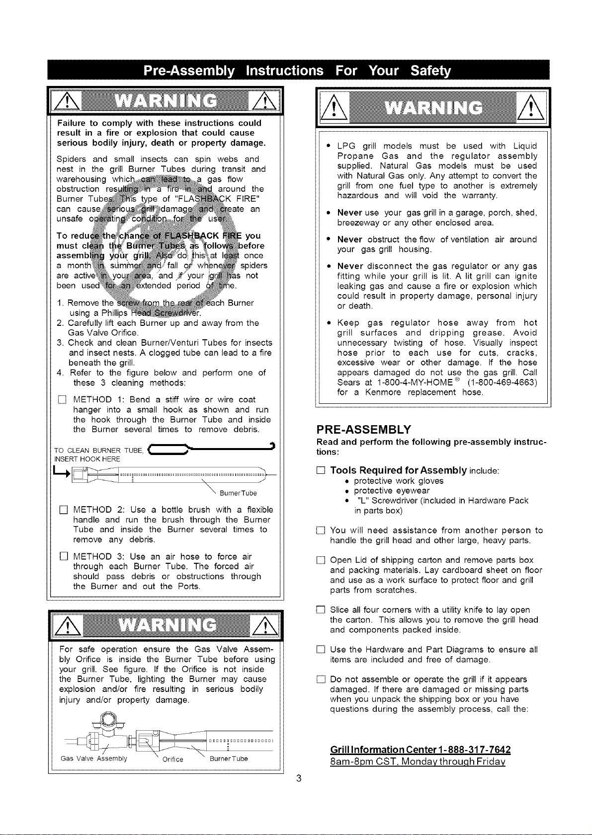
Spiders and small insects can spin webs and
nest in the grill Burner Tubes during transit and
warehousing whic gas flow
obstruction around the
Burner K FIRE"
can )ate an
unsafe o
To redu you
must cl,
assemb : once
a mont} spiders
are not
been _.
1. Remove th_ Burner
using a
2. Carefully lift each Burner up and away from the
Gas Valve Orifice.
3. Check and clean Burner/Venturi Tubes for insects
and insect nests. A clogged tube can lead to a fire
beneath the grill.
4. Refer to the figure below and perform one of
these 3 cleaning methods:
[] METHOD 1: Bend a stiff wire or wire coat
hanger into a small hook as shown and run
the hook through the Burner Tube and inside
the Burner several times to remove debris.
TO CLEAN BURNER TUBE,_
\
_ BurnerTube
[] METHOD 2: Use a bottle brush with a flexible
handle and run the brush through the Burner
Tube and inside the Burner several times to
remove any debris.
[] METHOD 3: Use an air hose to force air
through each Burner Tube. The forced air
should pass debris or obstructions through
the Burner and out the Ports.
For safe operation ensure the Gas Valve Assem-
bly Orifice is inside the Burner Tube before using
your grill. See figure. If the Orifice is not inside
the Burner Tube, lighting the Burner may cause
explosion and/or fire resulting in serious bodily
injury and/or property damage.
BBOBBBOB000BOBOBOB[
Gas Valve Assembly Orifice BumerTube
LPG grill models must be used with Liquid
Propane Gas and the regulator assembly
supplied. Natural Gas models must be used
with Natural Gas only. Any attempt to convert the
grill from one fuel type to another is extremely
hazardous and will void the warranty.
Never use your gas grill in a garage, porch, shed,
breezeway or any other enclosed area.
Never obstruct the flow of ventilation air around
your gas grill housing.
Never disconnect the gas regulator or any gas
fitting while your grill is lit. A lit grill can ignite
leaking gas and cause a fire or explosion which
could result in property damage, personal injury
or death.
Keep gas regulator hose away from hot
grill surfaces and dripping grease. Avoid
unnecessary twisting of hose. Visually inspect
hose prior to each use for cuts, cracks,
excessive wear or other damage. If the hose
appears damaged do not use the gas grill. Call
Sears at 1-80O-4-MY-HOME ® (1-800-469-4663)
for a Kenmore replacement hose.
PRE-ASSEMBLY
Read and perform the following pre-assembly instruc-
tions:
[] Tools Required forAssembly include:
• protective work gloves
• protective eyewear
• "L" Screwdriver (included in Hardware Pack
in parts box)
[] You will need assistance from another person to
handle the grill head and other large, heaw parts.
[]
[]
[]
Open Lid of shipping carton and remove parts box
and packing materials. Lay cardboard sheet on floor
and use as a work surface to protect floor and grill
parts from scratches.
Slice all four corners with a utility knife to lay open
the carton. This allows you to remove the grill head
and components packed inside.
Use the Hardware and Part Diagrams to ensure all
items are included and free of damage.
[] Do not assemble or operate the grill if it appears
damaged. If there are damaged or missing parts
when you unpack the shipping box or you have
questions during the assembly process, call the:
Grill information Center 1-888-317-7642
8am-8pm CST, Monday throu,qh Friday
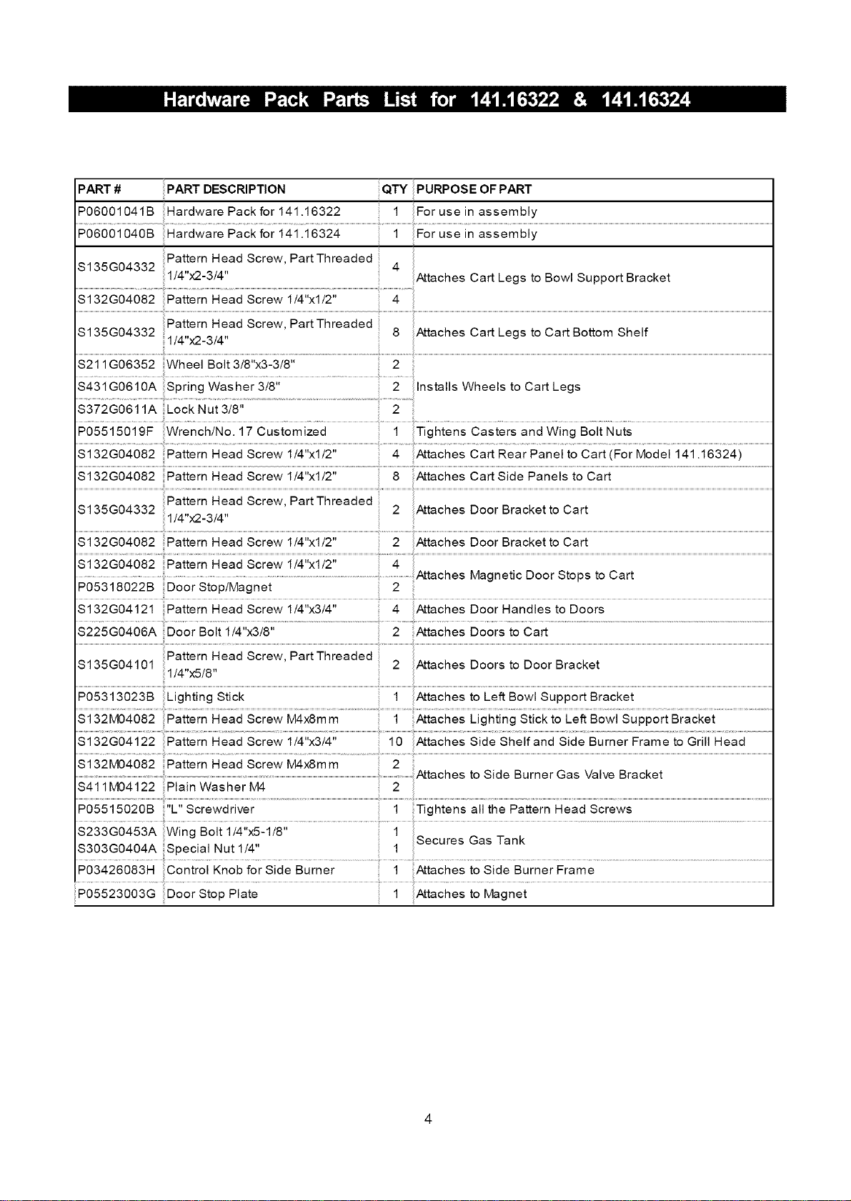
PART # PART DESCRIPTION QTY PURPOSE OF PART
P06O01041B Hardware Pack for141.16322 1 For use in assembly
PO600io40B i4i i6324 .....i For usein assembiy
Pattern H ad Screw, PartThreaded
S135G04332 1/4 x2-3/41 4 Attaches Cart Legs to Bowl Support Bracket
$132G04082 Pattern Head Screw 1/4"xl/2" 4
Pattern Head Screw PartThreaded
$135G04332 1/4"x2 3/4" ' 8 Attaches Cart Legs to Cart Bottom Shelf
$211G06352 Wheel Bolt 3/8"x3-3/8" 2
Installs Wheels to Cart Legs
S372GO611A Lock Nut 3/8" 2
$132G04082 Pattern Head Screw 1/4"xl/2" 8 Attaches Cart Side Panels to Cart
Pattern Head Screw PartThreaded
S135G04332 1/4"X2-3/4" ' 2 Attaches Door Bracketto Cart
S132G04082 Pattern Head Screw 1/4 xl/2 2 Attaches Door aracketto Cart
...................... .......................................................................................................................................Attaches Magnetic Door Stops to Cart
PO5318022B Door Stop!Magnet 2
$132G04121 Pattern Head Screw 1/4"x3/4" 4 Attaches Door Handles to Doors
S225GO406A Door Bolt 1/4"x3/8" 2 Attaches Doors to Cart
i
$135G04101 Pattern Head Screw, PartThreaded 2 Attaches Doors to Door Bracket
1/4"x5/8"
$132M04082 Pattern Head Screw M4xemm 2
PO5515020B "L" Screwdriver 1
S233G0453AW;ngBoiiii4;;xS:iiS"..................................................i
S3O3GO404A Special Nut 1/4" 1
Attaches to Side Burner Gas Valve Bracket
Tightens all the Pattern Head Screws
P034260831q Control Knob for side Burner ............................i Atiaches to Side Burner Frame .............................................................................................
P05523003G Door Stop Plate 1 Attaches to Magnet
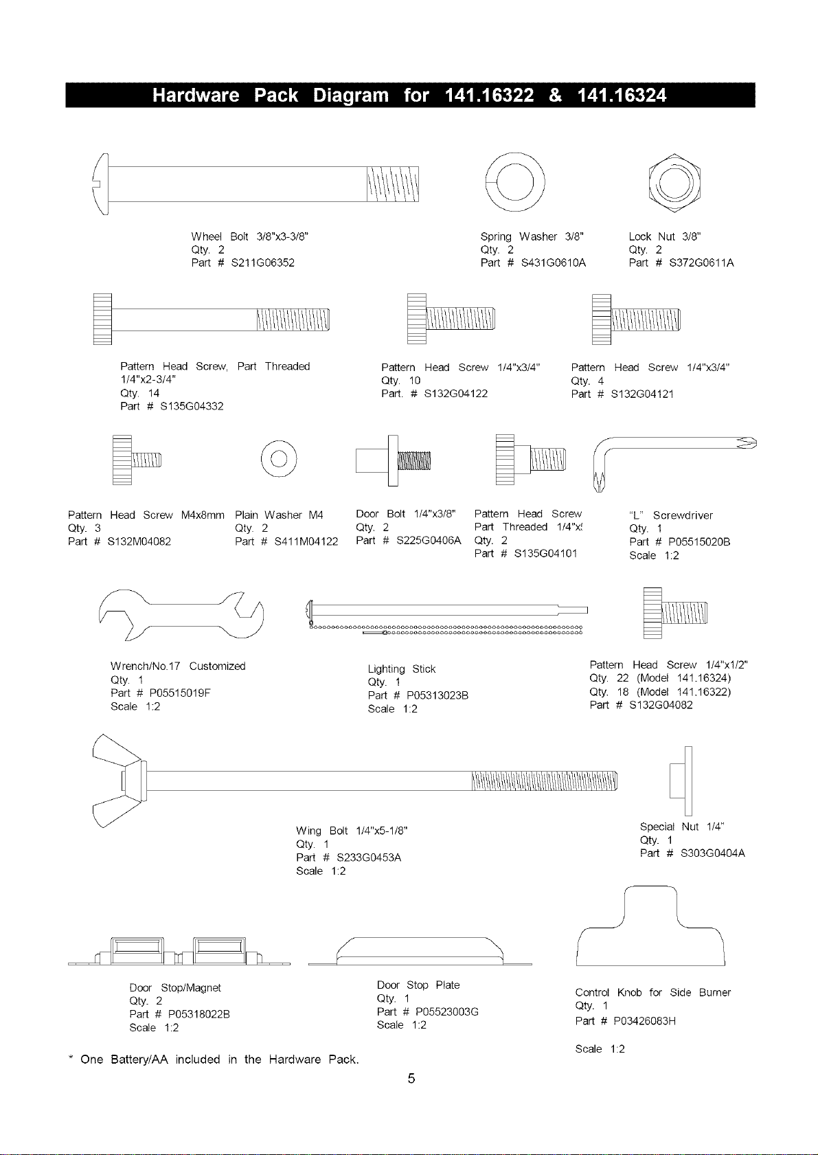
Wheel Bolt 3/8"x3-3/8"
Qty. 2
Part # $211G06352
Spring Washer 3/8"
Qty. 2
Part # S431G0610A
Lock Nut 3/8"
Qty. 2
Part # S372G0611A
Pattern Head Screw, Part Threaded
1/4"x2-3/4"
Qty. 14
Part # $135G04332
Pattern Head Screw 1/4"x3/4"
Qty. 10
Part. # $132G04122
Pattern Head Screw 1/4"x3/4"
Qty. 4
Part # $132G04121
Pattern Head Screw M4x8mm Plain Washer M4
Qty. 3 Qty. 2
Part # $132M04082 Part # S411M04122
Door Bolt 1/4"x3/8" Pattern Head Screw
Qty. 2 Part Threaded 1/4"x_
Part # S225G0406A Qty. 2
Part # S135G04101
"L" Screwdriver
Qty. 1
Part # P05515020B
Scale 1:2
Wrench/No.17 Customized
Qty. 1
Part # PO5515019F
Scale 1:2
Lighting Stick
Qty. 1
Part # P05313023B
Scale 1:2
Pattern Head Screw 1/4"xl/2"
Qty. 22 (Model 141.16324)
Qty. 18 (Model 141.16322)
Part # $132G04082
Wing Bolt 1/4"x5-1/8"
Qty. 1
Part # S233G0453A
Scale 1:2
Special Nut 1/4"
Qty. 1
Part # S303G0404A
Door Stop/Magnet
Qty. 2
Part # P05318022B
Scale 1:2
* One Battery/AA included in the Hardware Pack.
Door Stop Plate
Qty. 1
Part # P05523003G
Scale 1:2
Control Knob for Side Burner
Qty. 1
Part # P03426083H
Scale 1:2
1
2
6
5
4
10
11
12
13
28
37
2O
14
22
19
38
17_
18
45
23
26
44
39
25
24 36
_27
43
42
46
7
1
2
4
10
11
12
13
28
37
20
14
22
19
18
41
4O
45
26
23
42
46
27
43
39
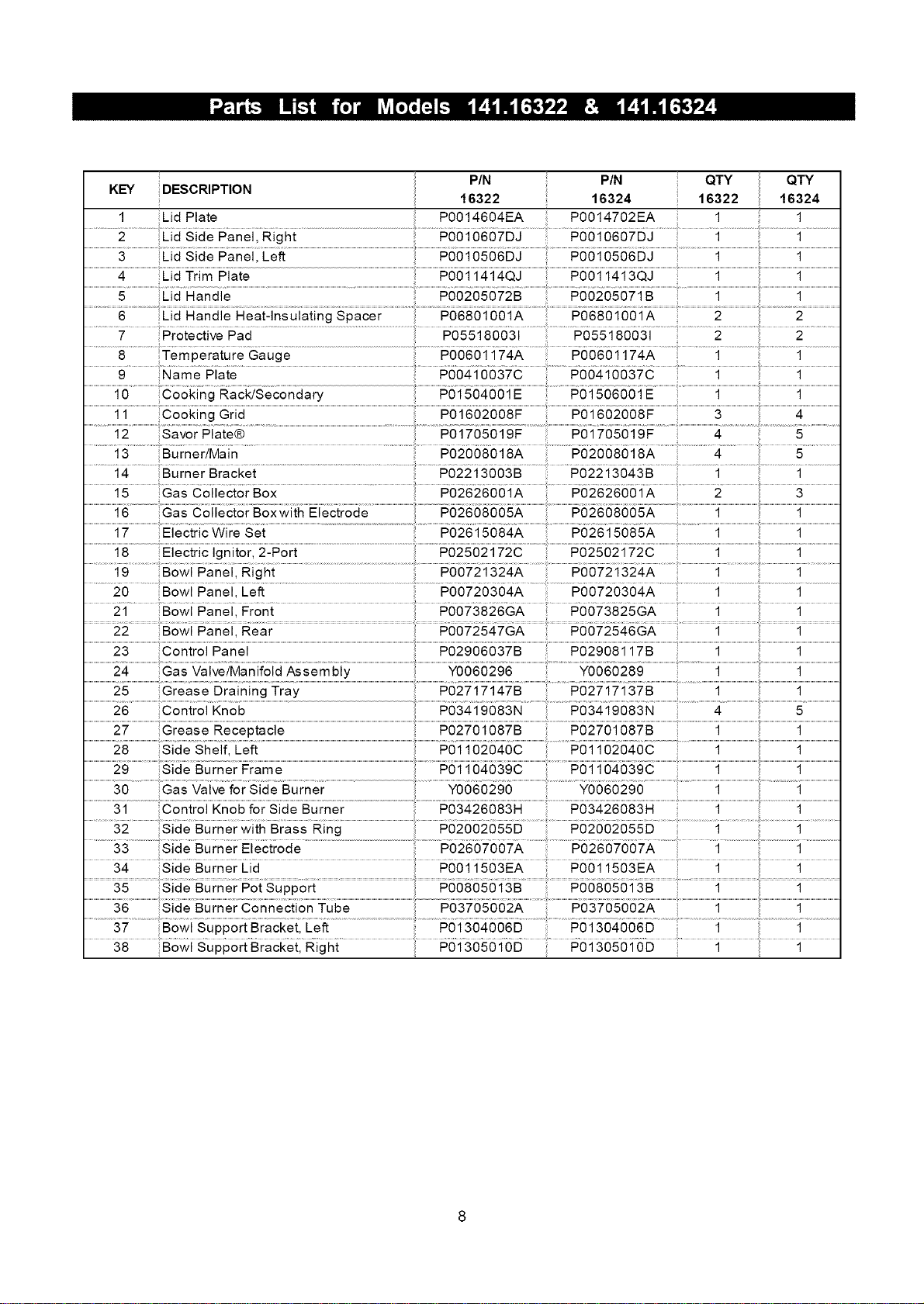
PIN :: PIN :: QTY QTY
DESCRIPTION 16322 16324 16322 16324
KEY
1 Lid Plate P0014604EA P0014702EA
Lid Side Panel, Right P0010607DJ P0010607DJ 1 1
.................................................................................................................................................................................................................................4 Lid Trim Plate ........................... .................................................. ................................................................i......................................................................................1.........................................
1
6 Lid Handle Heat-insulating Spacer P06801001A P06801001A 2 2
7 Protective Pad P055180031 P055180031 2 2
8 Temperature Gauge P00601174A P00601174A 1 1
9 Name Plate P00410037C P00410037C 1 1
.......................................................................................................................................................................................................... ............................................................................................................................>.........................................................................................................................................................................................................................................................................................
10 Cooking Rack/Secondary P01504001E P01506001E 1 1
11 Cooking Grid P01602008F P01602008F : 3 4
...........................i2 ...............................aie8 ....................................................................................................................................................................................................P0 i 7080i 9F ............................................................................................................4............................................................5.....................................
..........................................................................................13 Burner/Main P02008018A ................... .......................4........... 5.............
14 Burner Bracket P02213003B P02213043B 1 1
15 Gas Collector Box P02626001A P02626001A 2 3
.................................... .........................................................Pb2608008A .....................................................PO26OSooSA ..........................................i.....................................................................................1.........................................
17 Electric Wire Set P02615084A P02615085A 1 1
................................................18 Electric...............................................................................................................................................................................................................................................................................Ignitor, Z-Port ................................................................................................i.........................................................................................................1
............i 9.....................Bowl Panel, Right ...................................................................................P00721324A .............P0872"i324A 1 ....................................1
20 Bowl Panel, Left P00720304A P00720304A 1 1
21 .... Bowl Panel, Front #0073826GA #0073825GA 1
1
...............................22.................................. ................................................................................................................................................................................P0672547GA .............................................................................................1..................................................................................................................................1
.............................................................................}........................................................................................................................................................................................................................................................................................................................................................................................................................................................................................................................................................................................................................................................................................................................................
23 Control Panel P02906037B P02908117B 1 1
24 Gas Valve/Manifold Assembly Y0060296 Y0060289 ....................................i...................................................................................i.........................................
25 Grease Draining Tray P02717147B P02717137B
...............................26.................................................................................................................N.........................................................................................................4...............................................................................5.......................................
...............................27..........................................................................................................................................................................................................po2f0iosfB..........................................................................................................i....................................................................................i.........................................
..............................30 ............................Gas .....................................................................Y0686266 .....................................................................Y6686266 ...........................................................................i............................................................................i.........................................
..........................3i.........................Contr0i her................................................................................................................................................................................i..........................................................................i....................................
...........32.... BrassRing #026020855...................#02002055D...................................._...................................1..................
.............33................SideBurnerAiec{roae.........................................................;;.............P6266#86#A.........................#8265266#A .... 1..........................................1.................
34 Side Burner Lid P0011503EA P0011503EA 1 1
35 Side Burner Pot Support P00805013B P00805013B 1 1
36 Side Burner Connection Tube P03705002A P03705002A 1 1
38 Bowl Support Bracket, Right P01305010D P01305010D 1 1
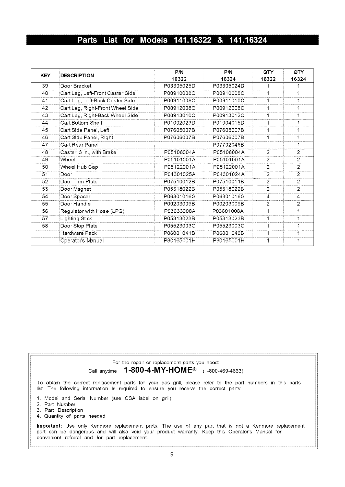
KEY DESCRIPTION PIN PIN : QTY QTY
16322 16324 16322 16324
39 Door Bracket P03305025D P03305024D 1 1
40 Cart Leg, Left-Front Caster Side P00910008C P00910008C 1 1
.............................................................. ......................................................................................................................................................................................................i.........................................1
42 Cart Leg, Right-Front Wheel Side P00912008C P00912008C 1 1
43 Cart Leg, Right-Back Wheel Side P00913010C P00913012C 1 1
44 Cart Bottom Shelf P01002023D P01004015D 1 1
45 Cart Side Panel, Left P07605007B P07605007B 1 1
46 Cart Side Panel, Right P07606007B P07606007B 1 1
47 Cart Rear Panel P07702046B 1
49 Wheel P05101001A P05101001A 2 2
50 Wheel Hub Cap P05122001A P05122001A 2 2
.............51......................Door .......................................................................................................................................................P04301025A ...............P0430 i024A ..................2.....................................2......................
52 Door Trim Plate P0751OO12B P07510011B 2 2
..................................................................................................................................................................................................................................................................................................................................................................................................................................................................................................................................................................................................................................>..........................................................................................................................................................................
53 Door Magnet P05318022B P05318022B 2 2
55 Door Handle PO0203009B P00203009B 2 2
.......................................................................................56 Regulator with Hose (LPG) P03633008A ...... ....................................1 .................................1 ...........
.............5# ..................'lighting Stick ...........................................................................P05313023B P05313023B 1 1
........................................................................................................................................................................................................................................................................................................Hardware Pack ....................P06681 ..............................................#6866_6_6B...................................................i....................................................................1.................................
For the repair or replacement parts you need:
Call anytime 1-800-4-MY-HOME® (1-800-469-4663)
To obtain the correct replacement parts for your gas grill, please refer to the part numbers in this parts
list. The following information is required to ensure you receive the correct parts:
1. Model and Serial Number (see CSA label on grill)
2. Part Number
3. Part Description
4. Quantity of parts needed
Important: Use only Kenmore replacement parts. The use of any part that is not a Kenmore replacement
part can be dangerous and will also void your product warranty. Keep this Operator's Manual for
convenient referral and for part replacement.
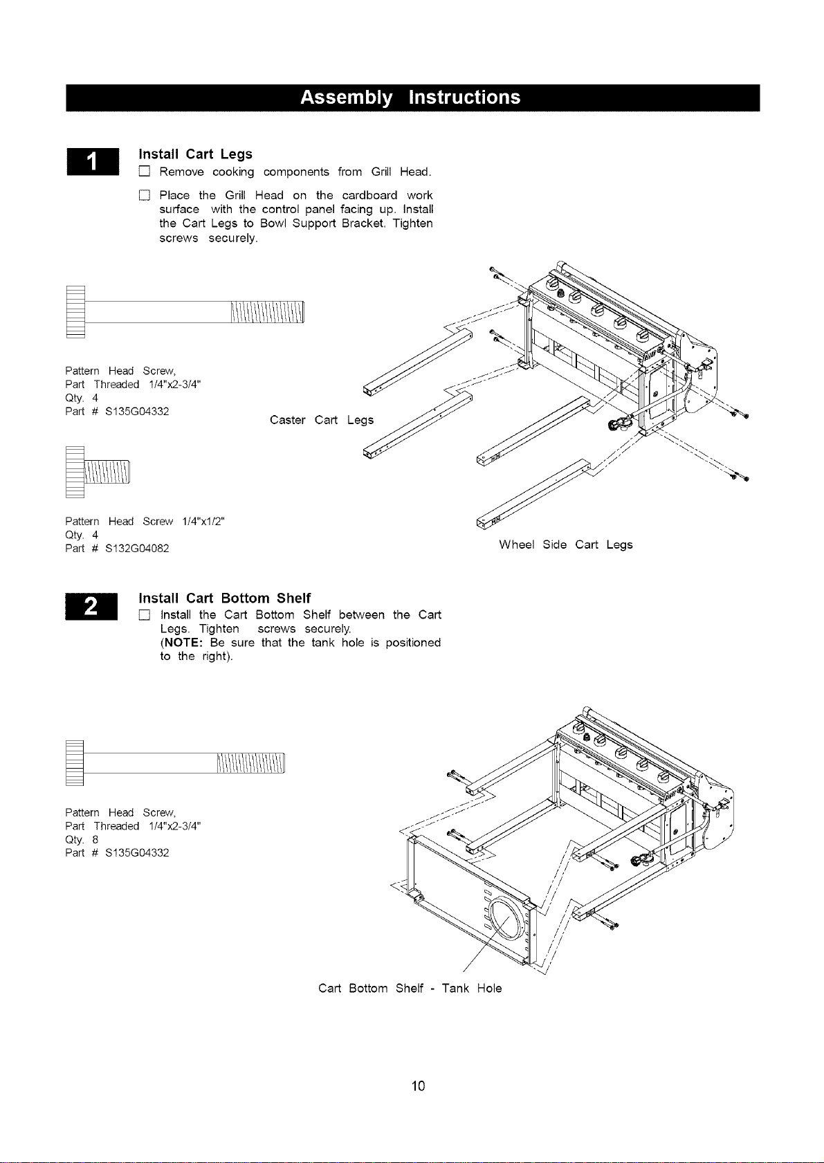
Install Cart Legs
[] Remove cooking components from Grill Head.
[] Place the Grill Head on the cardboard work
surface with the control panel facing up. install
the Cart Legs to Bowl Support Bracket. Tighten
screws securely.
Pattern Head Screw,
Part Threaded 1/4"x2-3/4"
Qty. 4
Part # S135G04332
Pattern Head Screw 1/4"xl/2"
Qty. 4
Part # S132G04082
Caster Cart Legs
Wheel Side Cart Legs
Install Cart Bottom Shelf
[] install the Cart Bottom Shelf between the Cart
Legs. Tighten screws securely.
(NOTE: Be sure that the tank hole is positioned
to the right).
Pattern Head Screw,
Part Threaded 1/4"x2-3/4"
Qty. 8
Part # S135G04332
Cart Bottom Shelf - Tank Hole
10
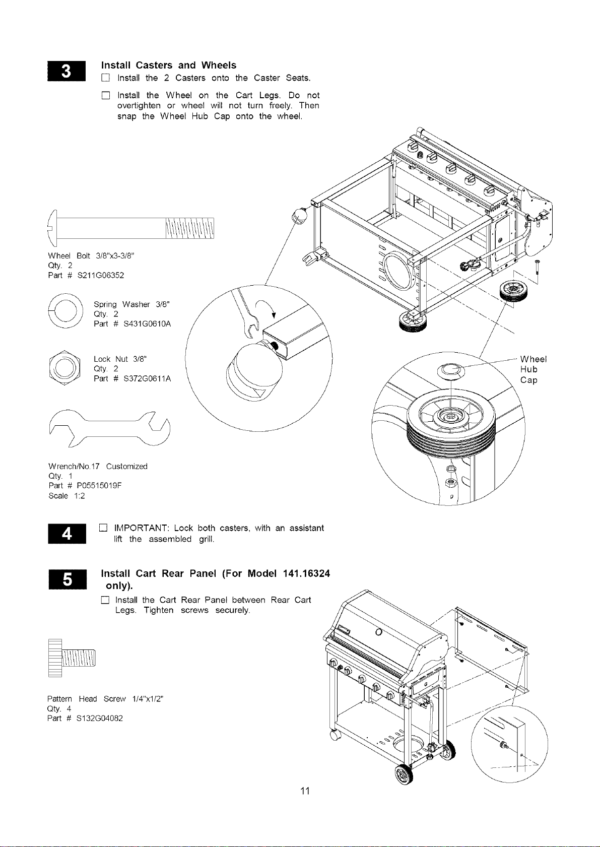
Install Casters and Wheels
[] install the 2 Casters onto the Caster Seats.
[] install the Wheel on the Cart Legs. Do not
overtighten or wheel will not turn freely. Then
snap the Wheel Hub Cap onto the wheel.
Wheel Bolt 3/8"x3-3/8"
Qty. 2
Part # $211G06352
Spring Washer 3/8"
Qty. 2
Part # S431G0610A
Lock Nut 3/8"
Qty. 2
Part # S372G0611A
Wheel
Hub
Cap
Wrench/No.17 Customized
Qty. 1
Part # P05515019F
Scale 1:2
[] IMPORTANT: Lock both casters, with an assistant
lift the assembled grill.
Install Cart Rear Panel (For Model 141.16324
only).
[] Install the Cart Rear Panel between Rear Cart
Legs. Tighten screws securely.
Pattern Head Screw 1/4"xl/2"
Qty. 4
Part # $132G04082
11
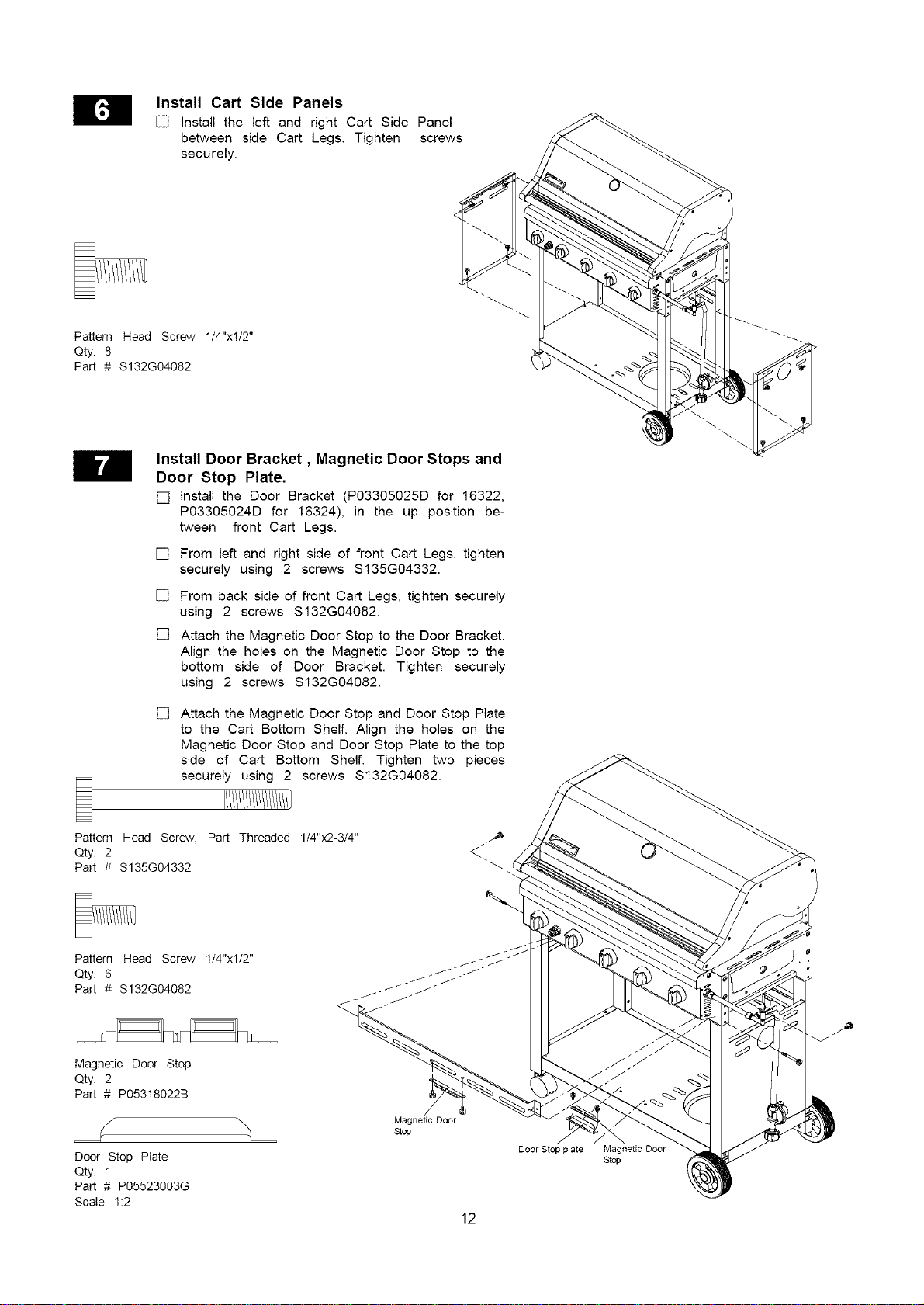
Install Cart Side Panels
[] install the left and right Cart Side Panel
between side Cart Legs. Tighten screws
securely.
Pattern Head Screw 1/4"xl/2"
Qty. 8
Part # $132G04082
Install Door Bracket, Magnetic Door Stops and
Door Stop Plate.
[] install the Door Bracket (P03305025D for 16322,
P03305024D for 16324), in the up position be-
tween front Cart Legs.
[]
[]
[]
From left and right side of front Cart Legs, tighten
securely using 2 screws S135G04332.
From back side of front Cart Legs, tighten securely
using 2 screws S132G04082.
Attach the Magnetic Door Stop to the Door Bracket.
Align the holes on the Magnetic Door Stop to the
bottom side of Door Bracket. Tighten securely
using 2 screws S132G04082.
[]
Pattern Head Screw, Part Threaded 1/4"x2-3/4"
Qty. 2
Part # S135G04332
Attach the Magnetic Door Stop and Door Stop Plate
to the Cart Bottom Shelf. Align the holes on the
Magnetic Door Stop and Door Stop Plate to the top
side of Cart Bottom Shelf. Tighten two pieces
securely using 2 screws S132G04082.
Pattern Head Screw 1/4"xl/2"
Qty. 6
Part # S132G04082
Magnetic Door Stop
Qty. 2
Part # P05318022B
Door Stop Plate
Qty. 1
Part # P05523003G
Scale 1:2
Magnetic Door
Stop
12
Door Stop plate Magnetic Door
Stop
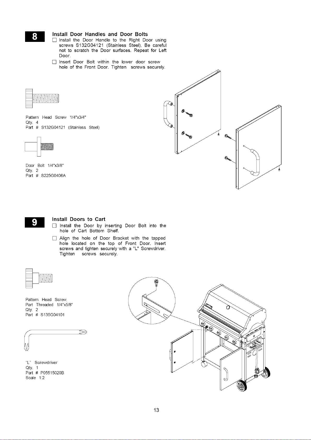
Install Door Handles and Door Bolts
[] install the Door Handle to the Right Door using
screws $132G04121 (Stainless Steel). Be careful
not to scratch the Door surfaces. Repeat for Left
Door.
[] insert Door Bolt within the lower door screw
hole of the Front Door. Tighten screws securely.
Pattern Head Screw 1/4"x3/4"
Qty. 4
Part # S132G04121 (Stainless Steel)
Door Bolt 1/4"x3/8"
Qty. 2
Part # S225G0406A
Install Doors to Cart
[] Install the Door by inserting Door Bolt into the
hole of Cart Bottom Shelf.
[] Align the hole of Door Bracket with the tapped
hole located on the top of Front Door. Insert
screws and tighten securely with a "L" Screwdriver.
Tighten screws securely.
Pattern Head Screw,
Part Threaded 1t4"x5/8"
Qty. 2
Part # $135G04101
"L" Screwdriver
Qty. 1
Part # P05515020B
Scale 1:2
13
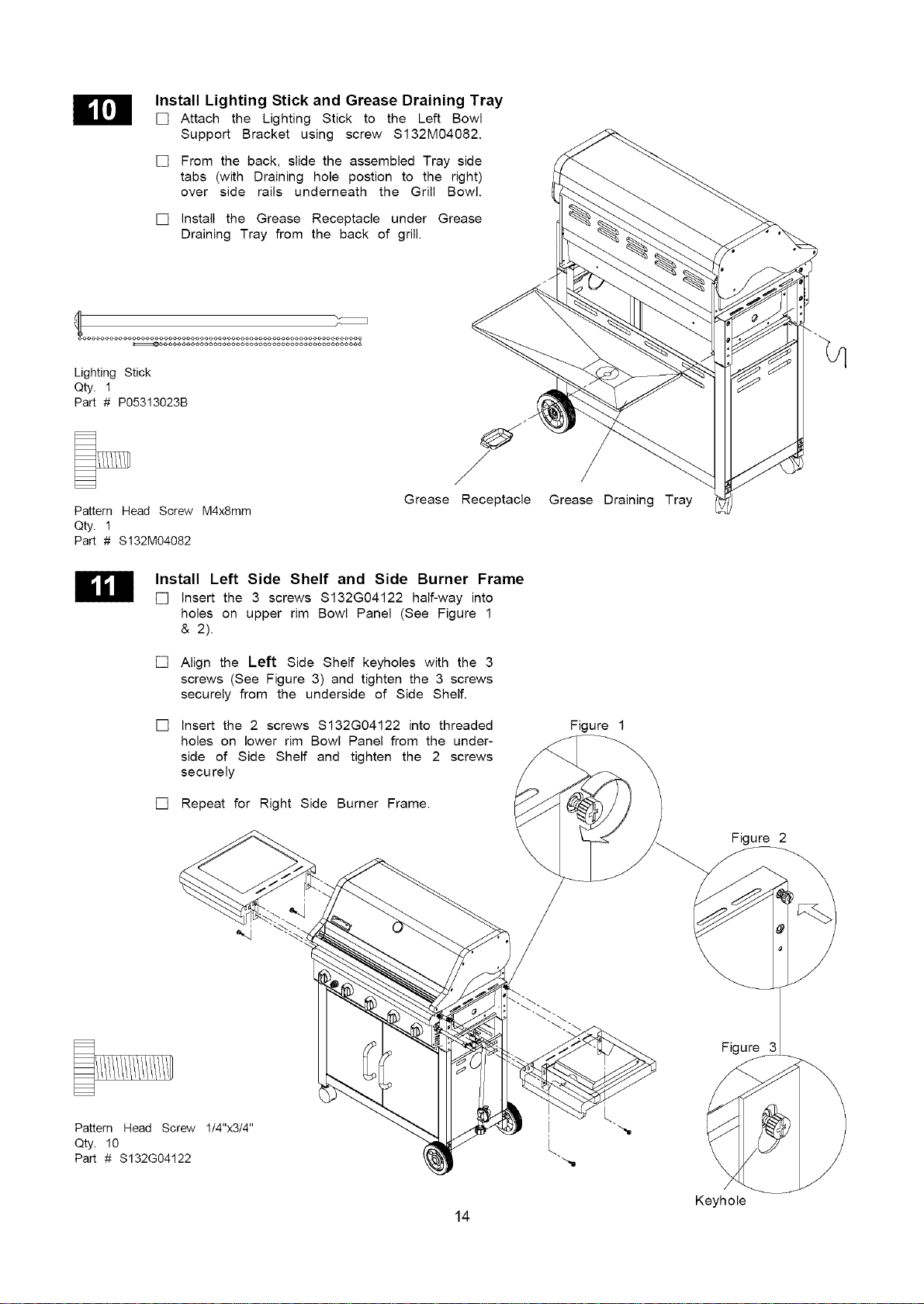
Install Lighting Stick and Grease Draining Tray
[] Attach the Lighting Stick to the Left Bowl
Support Bracket using screw $132M04082.
[] From the back, slide the assembled Tray side
tabs (with Draining hole postion to the right)
over side rails underneath the Grill Bowl.
[] install the Grease Receptacle under Grease
Draining Tray from the back of grill.
Lighting Stick
Qty. 1
Part # P05313023B
Pattern Head Screw M4x8mm
Qty. 1
Part # $132M04082
Grease Receptacle
Install Left Side Shelf and Side Burner Frame
[] Insert the 3 screws S132G04122 half-way into
holes on upper rim Bowl Panel (See Figure 1
& 2).
[] Align the Left Side Shelf keyholes with the 3
screws (See Figure 3) and tighten the 3 screws
securely from the underside of Side Shelf.
[] Insert the 2 screws S132G04122 into threaded
holes on lower rim Bowl Panel from the under-
side of Side Shelf and tighten the 2 screws
securely
[] Repeat for Right Side Burner Frame.
Grease Draining Tray
Figure 1
Figure 2
Figure
Pattern Head Screw 1/4"x3/4"
Qty. 10
Part # S132G04122
Keyhole
14
Install Side Burner Kit
[] Insert the Side burner Gas Valve Assembly into
Side Burner Tube (See Figure 1). Be sure the
orifice is inside the Burner Tube properly (see
warning on Page 3), or lighting the burner may
cause explosion and/or fire.
[]
[]
Insert the Side Burner Gas Valve Assembly
through the Side Burner Gas Valve Hole on the
Side Burner Frame. Align the 2 holes on the
Side Burner Frame with the threaded holes on
the Side Burner Gas Valve Bracket. Then insert
the two (2) screws and washers provided and
tighten securely.
Fasten the Control Knob onto the Side Burner
Gas Valve Stem. Be sure that the OFF position
faces the Burner.
[] Connect the Electric Wire terminal from Side
Burner with the other from Grill Head as shown.
Bind the connected Electric Wire and Side
Burner Connection Tube together using the
supplied Fastening Band.(Note: located in
Operator's Manual plastic bag).
[]
[]
[]
The gap between the Side Burner Electrode Tip
and the Side Burner Port should be
approximately 1/8"~ 3/16". If the gap is wider
than 3/16", use a pair of long nose pliers and
gently bend the Electrode Tip toward the burner.
Cut and remove Fastening Band from Side
Burner and Pot Support before use.
Place the Side Burner Pot Support into the Side
Burner Frame.
[] Place the Side Burner Wind Shield on the Side
Burner Frame.
Side Burner
Pot Support
Pattern Head Screw M4x8mm
Qty. 2
Part # $132M04082
©
Plain Washer M4
Qty. 2
Part # S411M04122
Electrical connection
Figure
Control Knob for Side Burner
Qty. 1
Part # P03426083H
Scale 1:2
Fastening Band
Qty. 1
15
1/8.~3/16. BURNER
PORT
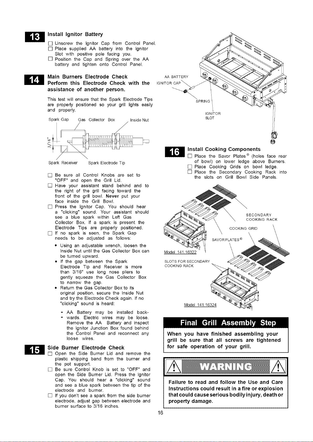
Install Ignitor Battery
[] Unscrew the ignitor Cap from Control Panel.
[] Place supplied AA battery into the Ignitor
Slot with positive pole facing you.
[] Position the Cap and Spring over the AA
battery and tighten onto Control Panel.
Main Burners Electrode Check
Perform this Electrode Check with the
assistance of another person.
This test will ensure that the Spark Electrode Tips
are properly positioned so your grill lights easily
and properly.
Spark Gap Gas Collector Box Inside Nut
AA BATTERY
IGNITOR CAP_ j_
---.<.
SPRING
IGNITOR
SLOT
Spark Receiver Spark Electrode Tip
[] Be sure all Control Knobs are set to
"OFF" and open the Grill Lid.
[] Have your assistant stand behind and to
the right of the grill facing toward the
front of the grill bowl. Never put your
face inside the Grill Bowl.
[] Press the Ignitor Cap. You should hear
a "clicking" sound. Your assistant should
see a blue spark within Left Gas
Collector Box. if a spark is present the
Electrode Tips are properly positioned.
[] if no spark is seen, the Spark Gap
needs to be adjusted as follows:
• Using an adjustable wrench, loosen the
inside Nut until the Gas Collector Box can
be turned upward.
• if the gap between the Spark
Electrode Tip and Receiver is more
than 3/16" use long nose pliers to
gently squeeze the Gas Collector Box
to narrow the gap.
• Return the Gas Collector Box to its
original position, secure the inside Nut
and try the Electrode Check again, if no
"clicking" sound is heard:
- AA Battery may be installed back-
- wards. Electric wires may be loose.
Remove the AA Battery and inspect
the ignitor Junction Box found behind
the Control Panel and reconnect any
loose wires.
Side Burner Electrode Check
[] Open the Side Burner Lid and remove the
plastic shipping band from the burner and
the pot support.
[] Be sure Control Knob is set to "OFF" and
open the Side Burner Lid. Press the Ignitor
Cap. You should hear a "clicking" sound
and see a blue spark between the tip of the
electrode and burner.
[] If you don't see a spark from the side burner
electrode, adjust gap between electrode and
burner surface to 3/16 inches.
Install Cooking Components
[] Place the Savor Plates ® (holes face rear
of bowl) on lower ledge above Burners.
[] Place Cooking Grids on bowl ledge.
[] Place the Secondary Cooking Rack into
the slots on Grill Bowl Side Panels.
SECONDARY
COOKING RACK
Model 141.16322
SLOTS FOR SECONDARY
COOKING RACK
Model 141.16324
When you have finished assembling your
grill be sure that all screws are tightened
for safe operation of your grill.
16
Failure to read and follow the Use and Care
Instructions could result in a fire or explosion
that could cause serious bodilyinjury, death or
property damage.
CORRECT LP GAS TANK USE
[] LP Gas grill models are designed for use with a
standard 20 lb. Liquid Propane Gas (LP Gas) tank,
not included with gdll. Never connect your gas grill to
an LP Gas tank that exceeds this capacity. A tank of
approximately 12 inches in diameter by 18-1/2 inches
high is the maximum size LP Gas tank to use. You
must use an "OPD" gas tank which offers a listed
Overfill Prevention Device. This safety feature
prevents tank from being overfilled which can cause
malfunction of LP Gas tank, regulator and/or gdll.
[] The LP Gas tank must be constructed and marked
in accordance with the Specifications for LP-Gas
Cylinders of the U.S. Department of Transportation
(D.O.T.) or the National Standard of Canada, CAN/
CSA-B339, Cylinders, Spheres and Tubes for
Transportation of Dangerous Goods; and Commis-
sion, as applicable.
[] The LP Gas tank must have a shutoff valve,
terminating in an LP Gas supply tank valve outlet
that is compatible with a Type 1 tank connection
device. The LP Gas tank must also have a safety
relief device that has a direct connection with the
vapor space of the tank.
[] The tank supply system must be arranged for
vapor withdrawal.
[] The LP Gas tank used must have a collar
to protect the tank valve.
[] Never connect an unregulated LP gas tank to your
gas grill. The gas regulator assembly supplied with
your gas grill is adjusted to have an outlet pres-
sure of 11" water column (W.C.) for connection to
an LP gas tank. Only use the regulator and hose
assembly supplied with your gas grill. Replacement
re,qulators and hose assemblies must be those
specified by Sears. See Parts List.
[] Have your LP Gas dealer check the release valve
after every filling to ensure it remains free of defects.
[] Always keep LP Gas tank in upright position.
[] Do not subject the LP Gas tank to excessive heat.
[] Never store an LP Gas tank indoors. If you store
your gas grill in the garage always disconnect the
LP Gas tank first and store it safely outside.
[] LP Gas tanks must be stored outdoors in a well-
ventilated area and out of the reach of children.
[] Disconnected LP Gas tanks must not be stored in
a building, garage or any other enclosed area.
[] The regulator and hose assembly can be seen
after opening the doors (if applicable) and must be
inspected before each use of the grill. If there is
excessive abrasion or wear or if the hose is cut, it
must be replaced prior to using the grill again.
[] Never light your gas grill with the lid closed or
before checking to ensure the burner tubes are fully
seated over the gas valve orifices.
[] Never allow children to operate your grill. Do not
allow children or pets to play near your grill.
[] Use of alcohol or drugs may impair the ability to
assemble and operate the appliance.
[] Keep fire extinguisher readily accessible. In the
event of a oil/grease fire, do not attempt to
extinguish with water. Use type B extinguisher
or smother with dirt, sand or baking soda.
[] In the event of rain, cover the grill and turn off
the burner and gas supply.
[] Use your grill on a level, stable surface in an
area clear of combustible materials.
[] Do not leave grill unattended when in use.
[] Do not move the appliance when in use.
[] Allow the grill to cool before moving or storing.
[] Do not use your grill as a heater.
[] This grill is not intended to be installed in or on
recreational vehicles and/or boats.
A. Do not store a spare LP-Gas tank under or near
this appliance.
B. Never fill the tank beyond 80 percent full; and
C. If the information in "(a)" and "(b)" is not followed
exactly, a fire causing death or serious injury may
occur.
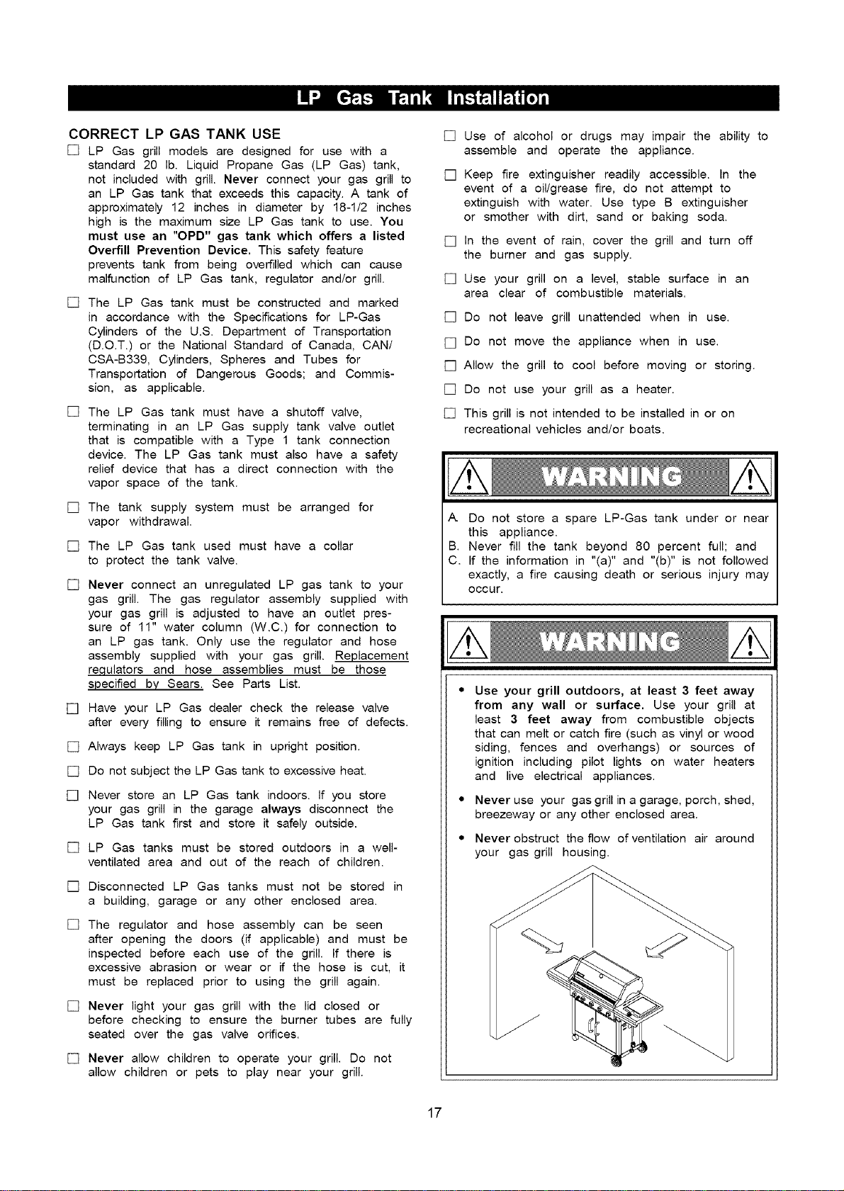
Use your grill outdoors, at least 3 feet away
from any wall or surface. Use your grill at
least 3 feet away from combustible objects
that can melt or catch fire (such as vinyl or wood
siding, fences and overhangs) or sources of
ignition including pilot lights on water heaters
and live electrical appliances.
Never use your gas grill in a garage, porch, shed,
breezeway or any other enclosed area.
Never obstruct the flow of ventilation air around
your gas grill housing.
/
17
NOTE about LP Gas Tank Exchange Programs
• Many retailers that sell grills offer you the option of
replacing your empty LP Gas tank through an ex-
change service. Use only those reputable exchange
companies that inspect, precision fill, test and certify
their tanks. Exchange your tank only for an OPD safety
feature-equipped tank as described in the LP Gas
tank section of this manual.
• Always keep new and exchanged LP Gas tanks in
an upright position during use, transit or storage.
• Leak test new and exchanged LP Gas tanks BE-
FORE
connecting one to your grill.
How to Leak Test your LP Gas Tank
For you r safety:
• All leak tests must be repeated each time your LP
Gas tank is exchanged or refilled.
• When checking for gas leaks do not smoke.
• Do not use an open flame to check for gas leaks.
• Your grill must be leak tested outdoors in a well-
ventilated area, away from ignition sources such
gas fired or electrical appliances. During the leak
keep your grill away from open flames or sparks.
• Do not use household cleaning agents. Damage
gas assembly components can result.
[] Use a clean paintbrush and a 50/50 mild soap
water solution.
[] Brush soapy solution onto LP Gas tank in the
areas indicated by the arrows. See tank diagram.
[] If growing bubbles appear do not use or move the
LP Gas tank. Call an LP Gas Supplier or your Fire
Department.
as
test,
to
and
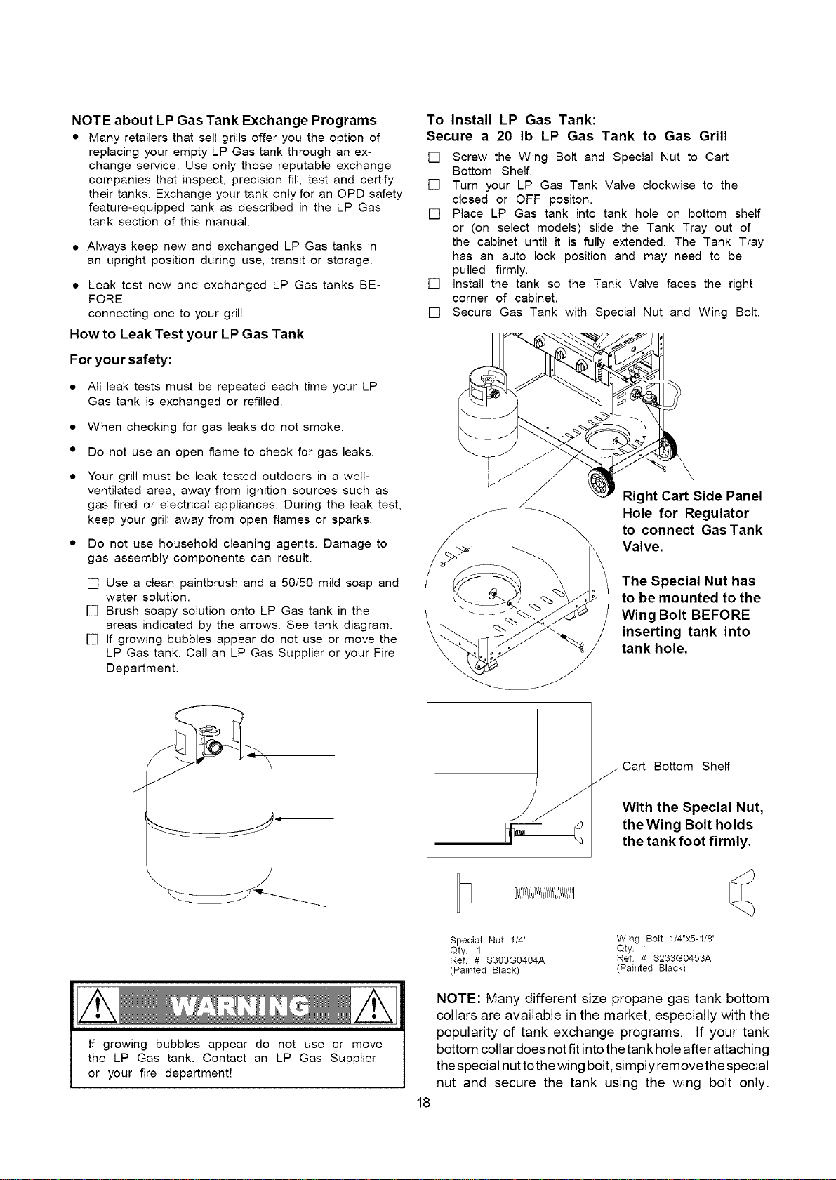
To Install LP Gas Tank:
Secure a 20 Ib LP Gas Tank to Gas Grill
[] Screw the Wing Bolt and Special Nut to Cart
Bottom Shelf.
[] Turn your LP Gas Tank Valve clockwise to the
closed or OFF positon.
[] Place LP Gas tank into tank hole on bottom shelf
or (on select models) slide the Tank Tray out of
the cabinet until it is fully extended. The Tank Tray
has an auto lock position and may need to be
pulled firmly.
[] install the tank so the Tank Valve faces the right
corner of cabinet.
[] Secure Gas Tank with Special Nut and Wing Bolt.
Right Cart Side Panel
Hole for Regulator
to connect Gas Tank
Valve.
The Special Nut has
to be mounted to the
Wing Bolt BEFORE
inserting tank into
tank hole.
J
-41
/
Cart Bottom Shelf
With the Special Nut,
the Wing Bolt holds
the tank foot firmly.
[1111111111%111111111111111111
If growing bubbles appear do not use or move
the LP Gas tank. Contact an LP Gas Supplier
or your fire department!
18
Special Nut 1/4" Wing Bolt 1/4"x5-1/8"
Qty 1 Qty 1
Ref # S303G0404A Ref # S233G0453A
(Painted Black) (Painted Black)
NOTE: Many different size propane gas tank bottom
collars are available in the market, especially with the
popularity of tank exchange programs, tf your tank
bottom collar does not fit into the tank hole after attaching
the special nut tothe wing bolt, simply remove the special
nut and secure the tank using the wing bolt only.
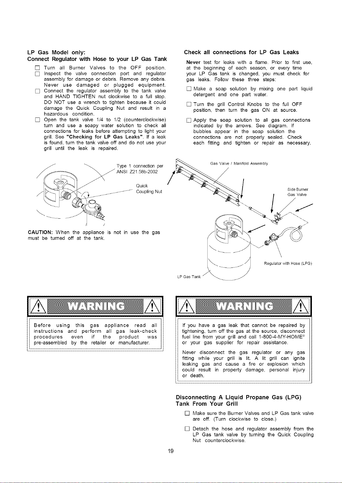
LP Gas Model only:
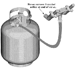
Connect Regulator with Hose to your LP Gas Tank
[] Turn all Burner Valves to the OFF position.
[] Inspect the valve connection port and regulator
assembly for damage or debris. Remove any debris.
Never use damaged or plugged equipment.
[] Connect the regulator assembly to the tank valve
and HAND TIGHTEN nut clockwise to a full stop.
DO NOT use a wrench to tighten because it could
damage the Quick Coupling Nut and result in a
hazardous condition.
[] Open the tank valve 1/4 to 1/2 (counterclockwise)
turn and use a soapy water solution to check all
connections for leaks before attempting to light your
grill. See "Checking for LP Gas Leaks". If a leak
is found, turn the tank valve off and do not use your
grill until the leak is repaired.
TYNPsl121.n5ZbC_t_°002per
Quick
Coupling Nut
CAUTION: When the appliance is not in use the gas
must be turned off at the tank.
Check all connections for LP Gas Leaks
Never test for leaks with a flame. Prior to first use,
at the beginning of each season, or every time
your LP Gas tank is changed, you must check for
gas leaks. Follow these three steps:
[] Make a soap solution by mixing one part liquid
detergent and one part water.
[] Turn the grill Control Knobs to the full OFF
position, then turn the gas ON at source.
[] Apply the soap solution to all gas connections
indicated by the arrows. See diagram. If
bubbles appear in the soap solution the
connections are not properly sealed. Check
each fitting and tighten or repair as necessary.
_ Gas / Manifold Assembly
Vatv_
Regulator with Hose (LPG)
Before using this gas appliance read all
instructions and perform all gas leak-check
procedures even if the product was
pre-assembled by the retailer or manufacturer.
If you have a gas leak that cannot be repaired by
tightening, turn off the gas at the source, disconnect
fuel line from your grill and call 1-8O0-4-MY-HOME e_
or your gas supplier for repair assistance.
Never disconnect the gas regulator or any gas
fitting while your grill is lit. A lit grill can ignite
leaking gas and cause a fire or explosion which
could result in property damage, personal injury
or death.
Disconnecting A Liquid Propane Gas (LPG)
Tank From Your Grill
[] Make sure the Burner Valves and LP Gas tank valve
are off. (Turn clockwise to close.)
[] Detach the hose and regulator assembly from the
LP Gas tank valve by turning the Quick Coupling
Nut counterclockwise.
19
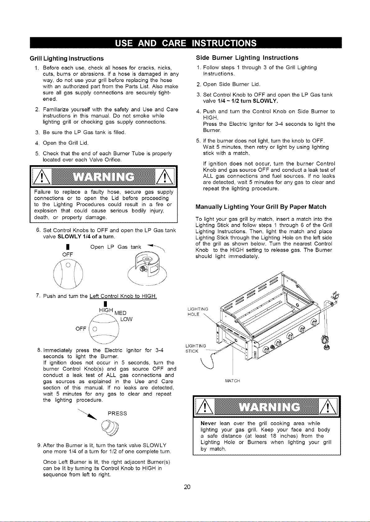
Grill Lighting Instructions
1. Before each use, check all hoses for cracks, nicks,
cuts, burns or abrasions. If a hose is damaged in any
way, do not use your grill before replacing the hose
with an authorized part from the Parts List. Also make
sure all gas supply connections are securely tight-
ened.
2. Familiarize yourself with the safety and Use and Care
instructions in this manual. Do not smoke while
lighting grill or checking gas supply connections.
3. Be sure the LP Gas tank is filled.
4. Open the Grill Lid.
5. Check that the end of each Burner Tube is properly
located over each Valve Orifice.
Failure to replace a faulty hose, secure gas supply
connections or to open the Lid before proceeding
to the Lighting Procedures could result in a fire or
explosion that could cause serious bodily injury,
death, or property damage.
6. Set Control Knobs to OFF and open the LP Gas tank
valve SLOWLY 1/4 of a turn.
I
OFF
Open LP Gas_
_-
7. Push and turn the Left Control Knob to HIGH.
HIGH MED
OFF _ LOW
8. Immediately press the Electric Ignitor for 3-4
seconds to light the Burner.
If ignition does not occur in 5 seconds, turn the
burner Control Knob(s) and gas source OFF and
conduct a leak test of ALL gas connections and
gas sources as explained in the Use and Care
section of this manual. If no leaks are detected,
wait 5 minutes for any gas to clear and repeat
the lighting procedure.
Side Burner Lighting Instructions
1. Follow steps 1 through 3 of the Grill Lighting
Instructions.
2. Open Side Burner Lid.
3. Set Control Knob to OFF and open the LP Gas tank
valve 1/4 ~ 1/2 turn SLOWLY.
Push and turn the Control Knob on Side Burner to
HIGH.
Press the Electric ignitor for 3-4 seconds to light the
Burner.
5. If the burner does not light, turn the knob to OFF.
Wait 5 minutes, then retry or light by using lighting
stick with a match.
If ignition does not occur, turn the burner Control
Knob and gas source OFF and conduct a leak test of
ALL gas connections and fuel sources. If no leaks
are detected, wait 5 minutes for any gas to clear and
repeat the lighting procedure.
Manually Lighting Your Grill By Paper Match
To light your gas grill by match, insert a match into the
Lighting Stick and follow steps 1 through 6 of the Grill
Lighting Instructions. Then, light the match and place
Lighting Stick through the Lighting Hole on the left side
of the grill as shown below. Turn the nearest Control
Knob to the HIGH setting to release gas. The Burner
should light immediately.
LIGHTING I
HOLE
LIGHTING /_
STICK
\
MATCH
PRESS
9. After the Burner is lit, turn the tank valve SLOWLY
one more 1/4 of a turn for 1/2 of one complete turn.
Never lean over the grill cooking area while
lighting your gas grill. Keep your face and body
a safe distance (at least 18 inches) from the
Lighting Hole or Burners when lighting your grill
by match.
Once Left Burner is lit, the right adjacent Burner(s)
can be lit by turning its Control Knob to HIGH in
sequence from left to right.
2O
Troubleshooting
If the grill fails to light :
1. Turn gas off at source and turn Control Knobs to
OFF. Wait at least 5 minutes for gas to clear, then
retry.
2. If your grill still fails to light, check gas supply
and connections.
3. Repeat lighting procedure. If your grill still fails
to operate, turn the gas off at source, turn the
Control Knobs to OFF, then check the following:
[] Misalignment of Burner Tubes over Orifices
Correction: Reposition Burner Tubes over Orifices.
[] Obstruction in gas line
Correction: Remove fuel line from grill. Do not
smoke! Open gas supply for one second to clear
any obstruction from fuel line. Close off gas supply
at source and reconnect fuel line to grill.
[]
[]
Plugged Orifice
Correction: Remove Burners from grill by remov-
ing the screw from the rear of each Burner using a
Phillips Head Screwdriver. Carefully lift each
Burner up and away from gas valve Orifice.
Remove the Orifice from gas valve and gently clear
any obstruction with a fine wire. Then reinstall all
Orifices, Burners and cooking components.
If an obstruction is suspected in Gas Valves or
Manifold, call the Grill Information Center.
[]
[]
Obstruction in Burner Tubes
Correction: Follow the Burner Tube cleaning
procedure on page 23 of this Operator's Manual.
Misalignment of Ignitor on Burner
Correction: Check for proper position of the
Electrode Tip as shown in step 14 page 16. The
gap between the Spark Electrode Tip and Spark
Receiver should be approximately 3/16". Adjust
if necessary. With the gas supply closed and all
Control Knobs set to OFF press the Electric
ignitor cap and check for the presence of a spark
at the Electrode.
[]
[]
Disconnected Electric Wires
Correction: inspect the Electric ignitor (see Parts
List) found behind the Control Panel. Connect loose
Electric wires to Junction Box and try to light the grill.
Weak AA battery
Correction: Unscrew the ignitor Cap and replace
the battery.
[]
If the grill still does not light you may need to
purge air from the gas line or reset the
regulator excess gas flow device. Note: This
procedure should be done every time a new
LP Gas tank is connected to your grill.
To purge air from your gas line and/or reset
the regulator excess gas flow device:
[] Turn Control Knobs to the OFF position.
[] Turn off the gas at the tank valve.
[] Disconnect regulator from LP Gas tank.
[] Let unit stand 5 minutes to allow air to purge
from gas line.
[] Reconnect regulator to the LP Gas tank.
[] Open the Grill Lid.
[] Turn tank valve on SLOWLY 1/4 of a turn.
[] Push and turn the LEFT Control Knob to HIGH.
[] Press Electric Ignitor for 3-4 seconds to light
the burners.
Should a FLASHBACK fire occur in or around
the Burner Tubes, follow the instructions below.
Failure to comply with these instructions could
result in a fire or explosion that could cause
serious bodily injury, death, or property damage.
• Shut off gas supply to the gas grill.
• Turn the Control Knobs to OFF position.
• Open the Grill Lid.
• Put out any flame with a Class B fire
extinguisher.
• Once the grill has cooled down, clean
the Burner Tubes and Burners according
to the cleaning instructions in this
Operator's Manual.
GRILL INFORMATION CENTER
Call 8am to 8pm CST 1-888-317-7642 Monday through Friday
21
Proper care and maintenance will keep your grill in top
operating condition and prolong its life. Follow these
cleaning procedures on a timely basis and your grill will
stay clean and operate with minimum effort.
CAUTION: Be sure your grill is OFF and cool before cleaning.
Cleaning The Cooking Grids
[] Before initial use, and periodically, wash your
Cooking Grids in a mild soap and warm water
solution. You can use a wash cloth or vegetable
brush to clean your Cooking Grids.
Cleaning The Savor Plates ®
[] Periodically you should wash the Savor Plates ®
in a soap and warm water solution. Use a
vegetable brush to remove stubborn burnt-on
cooking residue. Dry the Savor Plates ® thoroughly
before you reinstall them into the cooking bowl.
Cleaning The Grease Tray and Receptacle
[] To reduce the chance of fire, the Grease Draining
Tray and Grease Receptacle (some models)
should be visually inspected before each grill use.
Remove any grease and wash Grease Tray and
Receptacle with a mild soap and warm water
solution.
Cleaning the Inside of the Grill Lid
[] Grease can have a tendency to build up on the
inside of the Grill Lid and could drip onto deck or
patio when the lid is opened. Visually inspect the
inside of the Grill Lid before each grill use. Remove
any grease and wash with a mild soap and warm
water solution.
Annual Cleaning of
[]
1.
2.
3.
4.
5.
6.
7.
8.
g.
The Grill Interior
Burning-off excess food after every cookout will
keep it ready for instant use. However,at least every
3 months you must give the entire grill a thorough
cleaning to minimize your risk of grease fire and
keep the grill in top shape. Follow these steps:
Turn all Burner Valves to the full OFF position.
Turn the LP gas tank valve to the full OFF position.
Disconnect the regulator from the gas tank. inspect
the hose with regulator assembly for cracking, cuts
or any other damage, and replace as neccessary.
Refer to the Parts List in this Operator's Manual.
Remove and clean the Savor Plates _, Cooking
Grids, Cooking Rack and Grill Burners.
Cover each Gas Valve Orifice with aluminum foil.
Brush the inside and bottom of the grill with a fiber
pad or nylon brush and wash with a mild soap and
warm water solution. Rinse thoroughly and let dry.
Remove aluminum foil from Orifices and check
each Orifice for obstruction.
Check each Spark Electrode, adjusting as needed.
The space between the Spark Electrode Tip and
Spark Receiver should be approximately 3/16".
Replace the Burners and adjust the Gas
Collector Box. The edge of the collector box should
be overlapping the Burner Port.
10. Replace Savor Plates ® and Cooking Grids.
11. Reconnect the gas source and observe the
Burner flame for correct operation.
Cleaning Exterior Surfaces:
Before initial use, and periodically thereafter, we
suggest you wash your grill using a mild soap and
warm water solution. You can use a wash cloth or
sponge for this process. Do not use a stiff wire or
brass brush. These will scratch stainless steel and
chip painted surfaces (varies by model) during the
cleaning process.
Cleaning Exterior Stainless Steel Surfaces:
Weathering and extreme heat can cause exterior
stainless steel surfaces to turn tan in color. Machine
oils used in the manufacturing process of stainless
steel can also cause this tanning color. After
removing any protective PVC film from the Grill Lid or
Control Panel use a Stainless Steel Cleaner to polish
the stainless steel surfaces of your grill. Never use
abrasive cleaners or scrubbers because they will
scratch and damage your grill. Follow these steps for
the best results.
1. Turn the LP Gas tank valve (clockwise) to the full
OFF position. Disconnect the regulator and hose
assembly from LP Gas tank. Cover exposed gas
fitting with aluminum foil.
2. Remove dirt or grease using a soft cloth and
polish stainless surfaces. Wipe with a soft cloth.
3. Remove aluminum foil from exposed gas fitting
and allow grill to air dry before attaching the
regulator and hose to your LP Gas tank.
Failure to comply with these instructions may
result in a hazardous situation which, if not
avoided, may result in injury.
Keep grill area clear and free from combustible
materials, gasoline and other flammable vapors
and liquids.
Do not obstruct the flow of air for combustion
and ventilation.
Keep the ventilation openings of the tank enclosure
cabinet free and clear of debris.
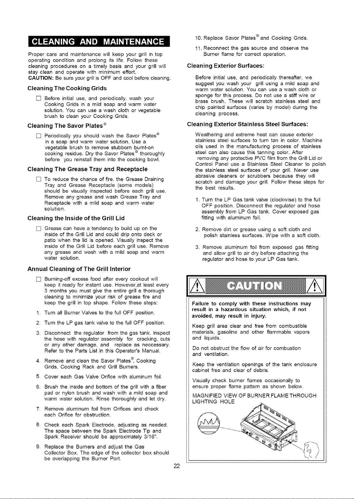
Visually check burner flames occasionally to
ensure proper flame pattern as shown below.
MAGNIFIED VIEW OF BURNER FLAME THROUGH
LIGHTING HOLE
22
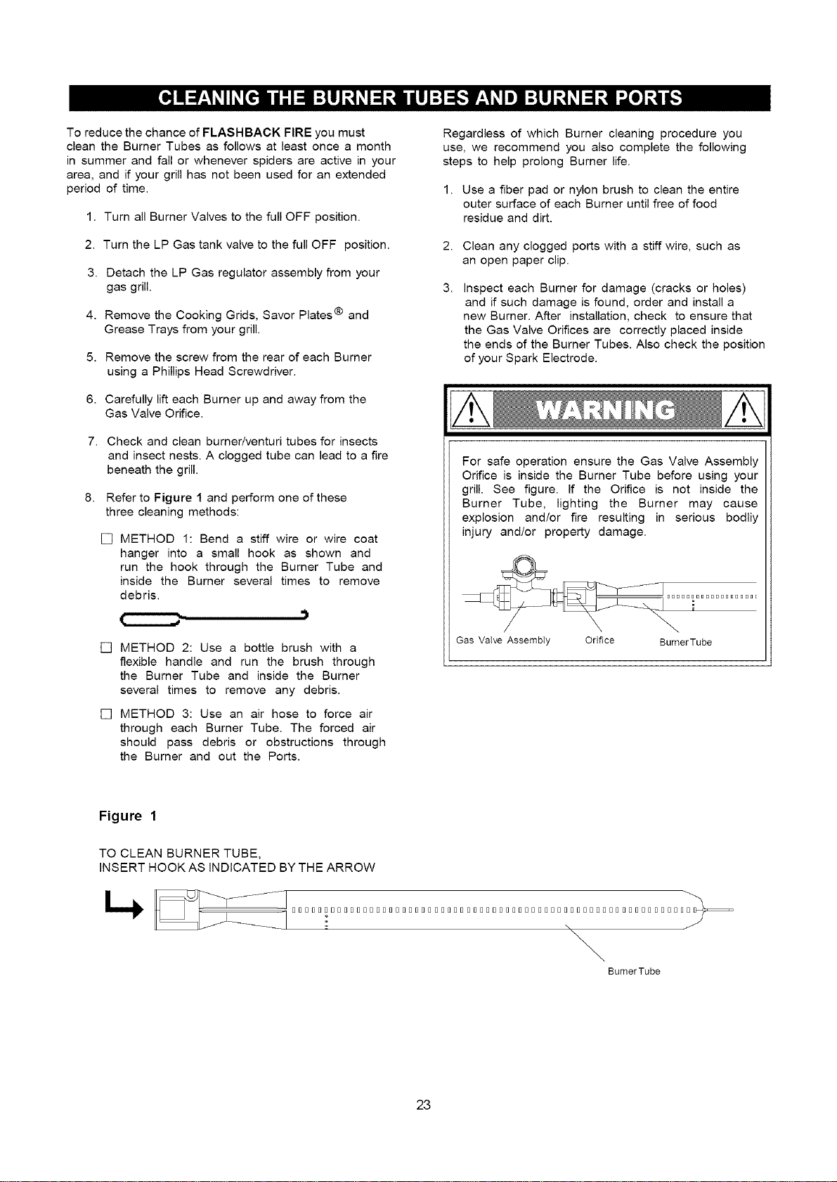
To reduce the chance of FLASHBACK FIRE you must
clean the Burner Tubes as follows at least once a month
in summer and fall or whenever spiders are active in your
area, and if your grill has not been used for an extended
period of time.
1. Turn all Burner Valves to the full OFF position.
2. Turn the LP Gas tank valve to the full OFF position.
3.
4.
Detach the LP Gas regulator assembly from your
gas grill.
Remove the Cooking Grids, Savor Plates ® and
Grease Trays from your grill.
5. Remove the screw from the rear of each Burner
using a Phillips Head Screwdriver.
6. Carefully lift each Burner up and away from the
Gas Valve Orifice.
Check and clean burner/venturi tubes for insects
and insect nests. A clogged tube can lead to a fire
beneath the grill.
Refer to Figure 1 and perform one of these
three cleaning methods:
[] METHOD 1: Bend a stiff wire or wire coat
hanger into a small hook as shown and
run the hook through the Burner Tube and
inside the Burner several times to remove
debris.
.)
[] METHOD 2: Use a bottle brush with a
flexible handle and run the brush through
the Burner Tube and inside the Burner
several times to remove any debris.
[] METHOD 3: Use an air hose to force air
through each Burner Tube. The forced air
should pass debris or obstructions through
the Burner and out the Ports.
Regardless of which Burner cleaning procedure you
use, we recommend you also complete the following
steps to help prolong Burner life.
1. Use a fiber pad or nylon brush to clean the entire
outer surface of each Burner until free of food
residue and dirt.
2. Clean any clogged ports with a stiff wire, such as
an open paper clip.
3.
Inspect each Burner for damage (cracks or holes)
and if such damage is found, order and install a
new Burner. After installation, check to ensure that
the Gas Valve Orifices are correctly placed inside
the ends of the Burner Tubes. Also check the position
of your Spark Electrode.
For safe operation ensure the Gas Valve Assembly
Orifice is inside the Burner Tube before using your
grill. See figure. If the Orifice is not inside the
Burner Tube, lighting the Burner may cause
explosion and/or fire resulting in serious bodily
injury and/or property damage.
Gas Valve AssembIy Orifice BumerTube
Figure 1
TO CLEAN BURNER TUBE,
INSERT HOOK AS INDICATED BY THE ARROW
_ _ SSSDSSSSSDSSSSDDSSSDSDSSDSSDSDSSDDDSSSSDSSSSSSSSSSDSSSSDDSSSD_
\
BurnerTube
23
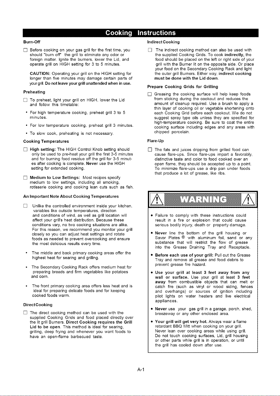
Burn-Off
[] Before cooking on your gas grill for the first time, you
should "burn off" the grill to eliminate any odor or
foreign matter. Ignite the burners, lower the Lid, and
operate grill on HIGH setting for 3 to 5 minutes.
CAUTION: Operating your grill on the HIGH setting for
longer than five minutes may damage certain parts of
your grill. Do not leave your grill unattended when in use.
Preheating
[] To preheat, light your grill on HIGH, lower the Lid
and follow this timetable:
• For high temperature cooking, preheat grill 3 to 5
minutes.
• For low temperature cooking, preheat grill 3 minutes.
• To slow cook, preheating is not necessary.
Cooking Temperatures
[] High setting: The HIGH Control Knob setting should
only be used to pre-heat your grill the first 3-5 minutes
and for burning food residue off the grill for 3-5 minut-
es after cooking is complete. Never use the HIGH
setting for extended cooking.
[] Medium to Low Settings: Most recipes specify
medium to low settings, including all smoking,
rotisserie cooking and cooking lean cuts such as fish.
An Important Note About Cooking Temperatures
[]
Unlike the controlled environment inside your kitchen,
variables like outside temperatures, direction
and conditions of wind, as well as grill location will
affect your grill's heat distribution. Because these
conditions vary, no two cooking situations are alike.
For this reason, we recommend you monitor your grill
closely so you can adjust heat settings and rotate
foods as needed to prevent overcooking and ensure
the most delicious results every time.
• The middle and back primary cooking areas offer the
highest heat for searing and grilling.
• The Secondary Cooking Rack offers medium heat for
preparing breads and firm vegetables like potatoes
and corn.
• The front primary cooking area offers less heat and is
ideal for preparing delicate foods and for keeping
cooked foods warm.
DirectCooking
[] The direct cooking method can be used with the
supplied Cooking Grids and food placed directly over
the lit grill Burners. Direct Cooking requires the Grill
Lid to be open. This method is ideal for searing,
grilling, deep frying and whenever you want foods to
have an open-flame barbecued taste.
Indirect Cooking
[] The indirect cooking method can also be used with
the supplied Cooking Grids. To cook indirectly, the
food should be placed on the left or right side of your
grill with the Burner lit on the opposite side. Or place
your food on the Secondary Cooking Rack and light
the outer grill Burners. Either way, indirect cooking
must be done with the Lid down.
Prepare Cooking Grids for Grilling
[] Greasing the cooking surface will help keep foods
from sticking during the cookout and reduces the
amount of cleanup required. Use a brush to apply a
thin layer of cooking oil or vegetable shortening onto
each Cooking Grid before each cookout. We do not
suggest spray type oils unless they are specified for
high-temperature cooking. Be sure to coat the entire
cooking surface including edges and any areas with
chipped porcelain.
Flare-Up
[] The fats and juices dripping from grilled food can
cause flare-ups. Since flare-ups impart a favorably,
distinctive taste and color to food cooked over an
open flame, they should be accepted up to a point.
To minimize flare-ups use a drip pan under foods
that produce a lot of grease, like ribs.
Failure to comply with these instructions could
result in a fire or explosion that could cause
serious bodily injury, death or property damage.
Never line the bottom of the grill housing or
Savor Plates ® with aluminum foil, sand or any
substance that will restrict the flow of grease
into the Grease Draining Tray and Receptacle.
Before each use of your grill: Pull out the Grease
Tray and remove all grease and food debris to
prevent grease fire hazard.
Use your grill at least 3 feet away from any
wall or surface. Use your grill at least 3 feet
away from combustible objects that can melt or
catch fire (such as vinyl or wood siding, fences
and overhangs) or sources of ignition including
pilot lights on water heaters and live electrical
appliances.
Never use your gas grill in a garage, porch, shed,
breezeway or any other enclosed area.
Your grill will get very hot. Always wear a flame
retardant BBQ Mitt when cooking on your grill.
Never lean over cooking areas while using grill.
Do not touch cooking surfaces, Lid, grill housing
or other parts while grill is in operation, or until
the grill has cooled down after use.
A-1
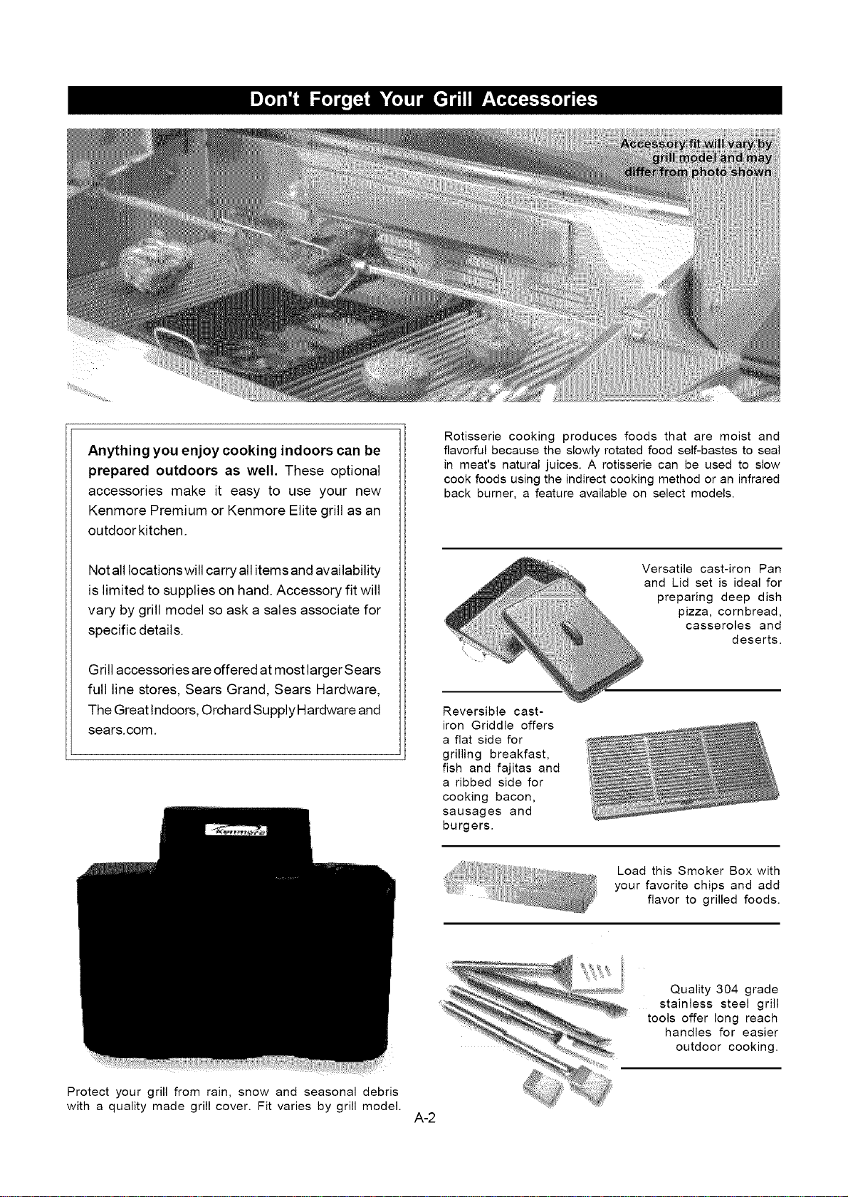
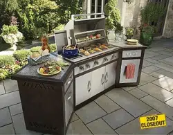
Anything you enjoy cooking indoors can be
prepared outdoors as well. These optional
accessories make it easy to use your new
Kenmore Premium or Kenmore Elite grill as an
outdoor kitchen.
Not all locations will carry all itemsand avai lability
is limited to supplies on hand. Accessory fit will
vary by grill model so ask a sales associate for
specific details.
Grill accessories are offered at most larger Sears
full line stores, Sears Grand, Sears Hardware,
The Great Indoors, Orchard Supply Hardware and
sears.com.
Rotisserie cooking produces foods that are moist and
flavorful because the slowly rotated food self-bastes to seal
in meat's natural juices. A rotisserie can be used to slow
cook foods using the indirect cooking method or an infrared
back burner, a feature available on select models.
Versatile cast-iron Pan
and Lid set is ideal for
preparing deep dish
pizza, cornbread,
casseroles and
deserts.
Reversible cast-
iron Griddle offers
a flat side for
grilling breakfast,
fish and fajitas and
a ribbed side for
cooking bacon,
sausages and
burgers.
Load this Smoker Box with
your favorite chips and add
flavor to grilled foods.
Protect your grill from rain, snow and seasonal debris
with a quality made grill cover. Fit varies by grill model.
A-2
Quality 304 grade
stainless steel grill
tools offer long reach
handles for easier
outdoor cooking.
Question:
Can I convert my grill from one fuel type to another in
other words from LPG to NG or vice versa?
Answer:
No, your gas grill is manufactured to exact specifications
and is certified for LPG (Liquid Propane Gas) or NG
(Natural Gas) use only. For your safety, conversion kits
are not available, nor will we sell or otherwise provide
parts or information to be used to convert your grill. Any
attempt to convert your grill is dangerous and will void
your warranty.
Question:
Are the serial and model numbers of my grill listed
somewhere for reference?
Answer:
The serial and model numbers are listed on a silver
CSA label placed on the grill. Depending on the grill
model, the silver CSA label will be located on the left or
right side bowl panel underneath the side shelf,
underneath the right side of the control panel, outside
left or right of control panel or on the back of the grill
cabinet.
Question:
My grill will not light properly. Why?
Answer:
Try this procedure:
1. Turn gas off at source and turn Control Knobs OFF.
Wait at ]east 5 minutes for gas to clear, then retry.
2. ]f your grill still falls to light, turn the Burner Control
Knob(s) and gas source OFF and conduct a leak test
of ALL gas connections and gas sources as
explained in the Use and Care section of this manual.
3. If no leaks are detected, wait 5 minutes for any gas to
clear and repeat the lighting procedure.
Question:
If my ignitor or battery is not working how can I light
my grill manually? And -Why would I need the silver
lighting stick that hangs from the side of my grill?
Answer:
If your ignition fails to work or your battery needs
replacing, you can light your grill through the Lighting
Hole on the side of the grill bowl using the Manual
Lighting Stick that hangs from the side of your grill. The
Lighting Stick is designed to hold a paper match and
allows you to safely insert a match through the Lighting
Hole without getting close to the Burner. Never remove
the Cooking Grids or Savor Plates ® and attempt to light
the grill from above. To light your gas grill manually,
insert a paper match into the Manual Lighting Stick and
follow steps 1 through 6 of the Basic Lighting
Procedures. Then, light the match and place it through
the Lighting Hole on the left side of the grill (location of
hole varies by grill model). Turn the nearest main
Burner Control Knob to the High setting to release gas.
The Burner should light immediately.
Question:
Sometimes I hear a humming sound coming from my
regulator. What causes this? And- My grill has a low
flame and sometimes will not light. Why?
Answer:
]he humming sound is gas flowing through the
regulator. A low volume of sound is normal and will not
interfere with the operation of your grill. Loud or
excessive regulator humming and/or low flow and
intermittent lighting may be caused by the regulator's
excess gas flow device. Opening the tank valve all the
way or too quickly is what triggers the regulator's
safety device to restrict gas flow, preventing excess
gas flow to your grill. Lighting the main Burner farthest
from the fuel source every time will help eliminate air
pockets in the manifold. Note: This procedure should
be done every time a new LP Gas tank is connected to
your grill.
[] Turn all Control Knobs to the OFF position.
[] Turn off the LP Gas tank at the tank valve.
[] Disconnect regulator from LP Gas tank.
[] Let unit stand for 5 minutes.
[] Reconnect regulator to the LP Gas tank.
[] Open grill Lid (or Side Burner Lid if you are lighting
the Side Burner)
[] Turn the tank valve slowly 1/4of one turn.
[] Light the left main Burner.
[] Turn the tank valve slowly one more _¼of one turn
for ½ of one complete turn.
[] Continue to light Burners moving towards the tank.
[] Do not turn tank valve more than ½ of one turn.
Question:
Where do I use my grill for safer operation and
better performance?
Answer:
[] Strong winds and low temperatures can affect the
heating and performance of your gas grill so
factor in these elements when positioning your
grill outdoors for cooking.
[]
[]
[]
[]
Use your grill at least 3 feet away from any wall or
surface.
Use your grill at least 3 feet away from
combustible objects that can melt or catch fire
(such as vinyl or wood siding, fences and
overhangs) or sources of ignition including pilot
lights on water heaters and live electrical
appliances.
Never use your gas grill in a garage, porch, shed,
breezeway or any other enclosed area.
Never obstruct the flow of ventilation air around
your gas grill housing.
A-3
Question:
The Regulator and Hose supplied with my gas grill
does not fit the older LP Gas tank I've used for
years. Why not?
Answer:
The U.S. Government regulates gas appliances and
LP Gas tanks. When regulations are changed the LP
Gas tank fittings are altered to insure compliance. If
your LP Gas tank does not fit the Regulator and Hose
supplied with your new grill, the tank is outdated and
must be replaced. Note: Effective April 1, 2002 all LP
Gas tanks sold must include an "OPD" Overfill
Prevention Device. The OPD tanks are identified by
their triangular-shaped valve wheel. This internal
device prevents the LP Gas tank from being
overfilled. Tanks without an OPD valve can not be
refilled.
Question:
Is it safe to clean my porcelain coated cooking grids
in the dishwasher?
Answer:
Clean your cooking grids by hand if there are any chips
or cracks in the porcelain finish and dry them thoroughly.
If no chips or cracks are present it should be safe to use
the dishwasher. Remember to dry the cooking grids
thoroughly before placing back onto your grill to
minimize rusting.
Question:
What causes grill parts to rust and what affect does
it have on mygrill?
Answer:
Rusting is a natural oxidation process and may
appear on cast-iron and steel parts. Rust will not
affect the short term performance of your grill.
To slow the rusting process on steel Cooking Grids
(select models) we recommend greasing the
Cooking Grids before and after each cookout. Use a
brush to apply a thin layer of cooking oil or vegetable
shortening onto each Cooking Grid. We do not
suggest spray type oils unless they are specified for
high-temperature cooking. Be sure to coat the entire
cooking surface including edges and any areas with
chipped porcelain.
Question:
Which is a better cooking surface to grill on;
porcelain coated steel / cast-iron cooking grids or
stainless steel grids?
Answer;
They all have their advantages. For traditional grilling
and searing meats, cast-iron or steel grids offer
better heat conductivity. To protect against the natural
rusting process, steel or cast-iron cooking grids offer
a porcelain finish which requires routine
maintenance to keep the grids well seasoned.
Stainless steel is popular with those who prefer less
maintenance.
A new innovative solution is available on select
models called stainless Therma-Core TM. This
Cooking Grid combines a heat conducting steel core
with an easy-to-clean stainless outer shell.
Question:
Some stainless steel grills specify 304 grade
construction while others do not mention a grade at
all? What is the difference?
Answer:
All stainless grades are not created equal. The 304
grade, also called 18-8 stainless steel, is prized for its
excellent resistance to rust and corrosion and good
performance at high temperatures, which makes it ideal
for grill construction.
304 grade stainless steel is by far the most popular
stainless steel and contains 18-20% chromium and
8-10% nickel, making it non-magnetic.
Some stainless steel grills are constructed of Type 430
stainless steel which contains 16-18% chromium but
generally less than 1% nickel. It is magnetic with less
corrosion and rust resistance and designed for limited
temperature use. Beware of stainless steel grills that
offer no claim of grade because what looks shiny on the
sales floor could become a problem on your patio.
How can you tell if a product is made of 304 grade
stainless? Take the simple magnet test. If a magnet
sticks to the stainless steel it is 430 grade. If a magnet
does not stick you can trust its 304 grade quality.
A-4
Your Home
For repair-in your home-of aH majo_ brand appliances,
lawn and garden equipment or heating and c_lmg systems_
no ma/tter who made it, no ma_er who sold it_
Fo_the replacement parts, accessories and
owner's manuals that you; need to do-it-yourself.
For SeaB professional installation d home appliances
and items like garage door openers and water heaters.
t -8004-MY-HOME '_
Ca/anytime_ day or _i_t (U.SA, a:ndCanada)
_w,sears.c_ www.sea[s,_a
Our Home
For repair of carp!-in items _ike vacuurns_ _awn equipment_
and eledronics, call or go onqine for the IIIocationof your nearest
Sears Parts & Repair Center.
Cat_anytim8, day o_night (U.S A. on_y}
www.sears_m
To purchase a protection agreement (U.S.A.)
or maintenance agreement (Canada) on a product serviced by Sears:
1_00-827_655 (us 1-800461-6665 (Cana_a_
Parapedir sewic}o de re#araca6n Au Canada pourse_'_tceen fsn_ais:
a domicHio, y p_ra ordenar p_ezas:
(1-800-533_937)
(1-888-7844427) _7w.sears.ca