Loading ...
Loading ...
Loading ...
40
OPERACIÓN
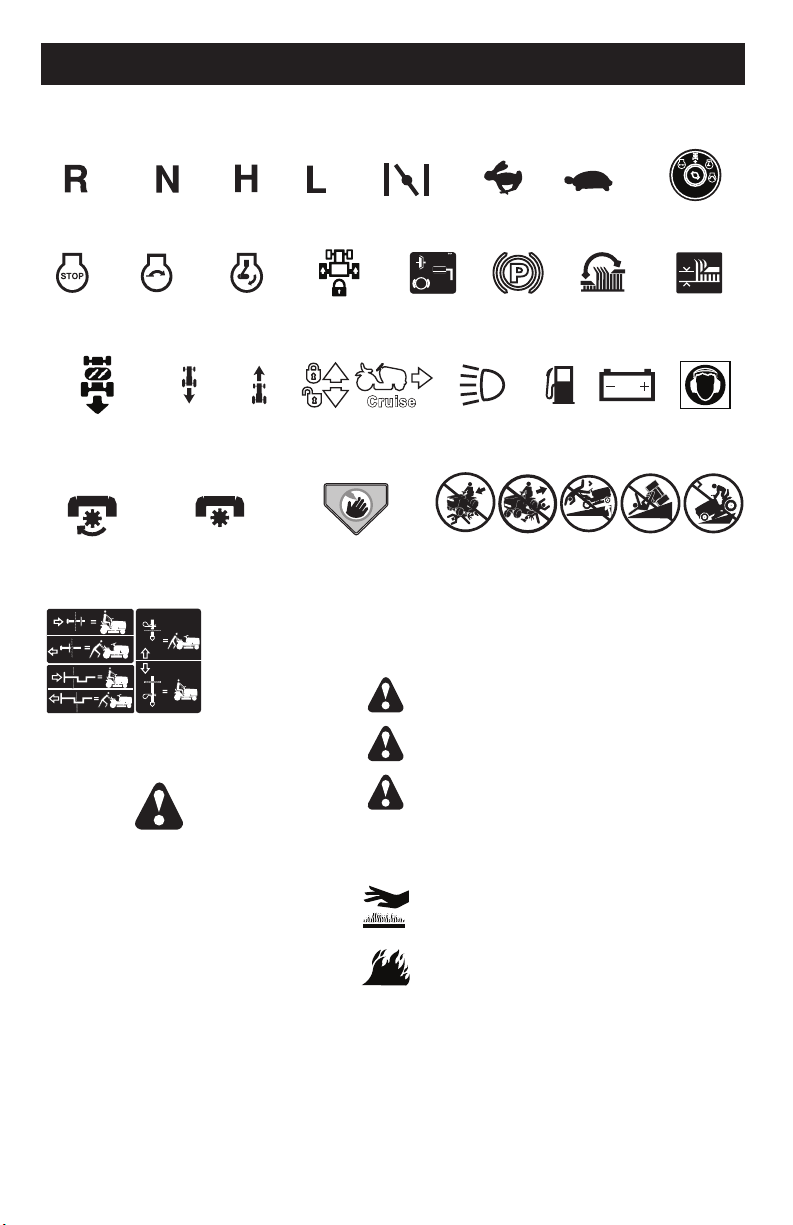
Estos símbolos pueden aparecer sobre su tractor o en la literatura proporcionada con el producto.
Aprenda y comprenda sus significados.
ESTRANGU-
LACIÓN
RÁPIDO LENTOMARCHA
ATRÁS
NEUTRO ALTO BAJO
MARCHA
ATRÁS
MARCHA
HACIA
ADELANTE
COMBUS-
TIBLE
MOTOR
APAGADO
ALTURA
DE LA
SEGADORA
MOTOR
ENCENDIDO
MOTOR
EN MARCHA
BATERÍA
LEVANTA-
MIENTO DE
LA SEGADORA
SISTEMA
FUNCIONAMIENTO
ATRÁS (ROS)
LUCES
ENSENDIDAS
INTERRUPTOR
DE IGNICIÓN
PEDAL DE
FRENO /
EMBRAGUE
PALANCA DE
MANDO CRUCERO
FRENO DE
ESTACION-
AMIENTO
RUEDA LIBRE
(Solamente para los
modelos automatico)
No seguir las siguientes
instrucciones puede provocar
heridas o muerte. Los símbolos
de aviso de seguridadse utilizan
para identificar informaciones de
seguridad relativas a peligros que
pueden provocar la muerte, heridas
graves y/o daños a la máquina.
PELIGRO indica un peligro que, si no se evita,
provoca muerte o lesiones graves.
ADVERTENCIA indica un peligro que, si no se evita,
puede provocar muerte o lesiones graves.
PRECAUCIÓN indica un peligro que, si no se evita,
puede provocar lesiones ligeras o moderadas.
PRECAUCIÓN cuando se utiliza sin el símbolo de
aviso, indica una situación que puede provocar
daños al tractor y/o al motor.
FUEGO indica un peligro que, si no se evita, puede
provocar la muerte, lesiones graves y/o danos
a la máquina.
SUPERFICIES CALIENTES indica un peligro que,
si no se evita, puede provocar la muerte, lesiones
graves y/o danos a la máquina.
EL CIERRE
DIFERENCIAL
PROTECCIÓN
DE OÍDO SE
REQUIERE
PELIGRO, GUARDE
LAS MANOS Y
LOS PIES LEJOS
15
15
MANTENGA EL
AREA DESPEJADA
PELIGROS DE
PENDIENTES
(VEA LA SECCIÓN DE LAS REGLAS DE SEGURIDAD)
ACCESORIO
DEL EMBRAGUE
ENGANCHADO
ACCESORIO
DEL EMBRAGUE
DESENGANCHADO
25
FRONT WHEEL TOE-IN/CAM BER
Your new tractor front wheel toe-in and
camber is set at the factory and is normal.
The front wheel toe-in and camber are not
adjustable. If damage has occurred to
affect the factory set front wheel toe-in or
camber, contact a Sears or other qualified
service center.
TO REMOVE WHEEL FOR REPAIRS
1. Block up axle securely.
2. Remove axle cover, retaining ring and
washers to allow wheel removal (rear
wheels have a square key - Do not lose).
3. Repair tire and reassemble.
NOTE: On rear wheels only: align grooves in
rear wheel hub and axle. Insert square key.
4. Replace washers and snap retaining ring
securely in axle groove.
5. Replace axle cover.
NOTE: To seal tire punctures and pre vent
flat tires due to slow leaks, purchase and
use tire sealant from Sears. Tire sealant also
pre vents tire dry rot and corrosion.
00
66
3
Retaining
Ring
Washers
Square
Key
(Rear Wheel Only)
Axle
Cover
TO START ENGINE WITH WEAK BAT TERY
WARNING: Lead-acid batteries gen er-
ate ex plo sive gases. Keep sparks, flame
and smoking ma te ri als away from bat ter ies.
Always wear eye pro tec tion when around
batteries.
If your battery is too weak to start the engine,
it should be recharged. (See "BATTERY" in
the MAINTENANCE section of this man u al).
If “jumper ca bles” are used for emer gen cy
starting, follow this pro ce dure:
IMPORTANT: Your tractor is equipped with
a 12 volt system. The other vehicle must also
be a 12 volt system. Do not use your tractor
battery to start other vehicles.
TO ATTACH JUMPER CABLES -
1. Connect one end of the RED cable to the
POSITIVE (+) terminal of each battery(A-
B), taking care not to short against tractor
chassis.
2. Connect one end of the BLACK ca ble
to the NEGA TIVE (-) terminal (C) of fully
charged battery.
3. Connect the other end of the BLACK
cable (D) to good chassis ground, away
from fuel tank and bat tery.
TO REMOVE CABLES, REVERSE ORDER -
1. BLACK cable first from chassis and then
from the fully charged battery.
2. RED cable last from both batteries.
Weak or
Dead
Battery
Fully
Charged
Battery
REPLACING BATTERY
WARNING: Do not short bat tery ter mi nals
by al low ing a wrench or any other object to
contact both terminals at the same time.
Before con nect ing battery, remove metal
bracelets, wrist watch bands, rings, etc.
Positive terminal must be connected first to
prevent spark ing from ac ci den tal grounding.
1. Lift seat pan to raised position.
02603
Keps
Nut
Positive
(Red)
Cable
Negative (Black)
Cable
Hex
Bolt
Terminal
Cover
2. Disconnect BLACK battery cable first then
RED battery cable and carefully remove
battery from trac tor.
3. Install new battery with terminals in same
position as old battery.
4. First connect RED battery cable to posi-
tive (+) terminal with hex bolt and keps
nut as shown. Tighten securely. Slide
terminal cover over terminal
5. Connect BLACK grounding cable to
negative (-) ter mi nal with remaining hex
bolt and keps nut. Tighten se cure ly.
Seat pan
Loading ...
Loading ...
Loading ...