Loading ...
Loading ...
Loading ...
12
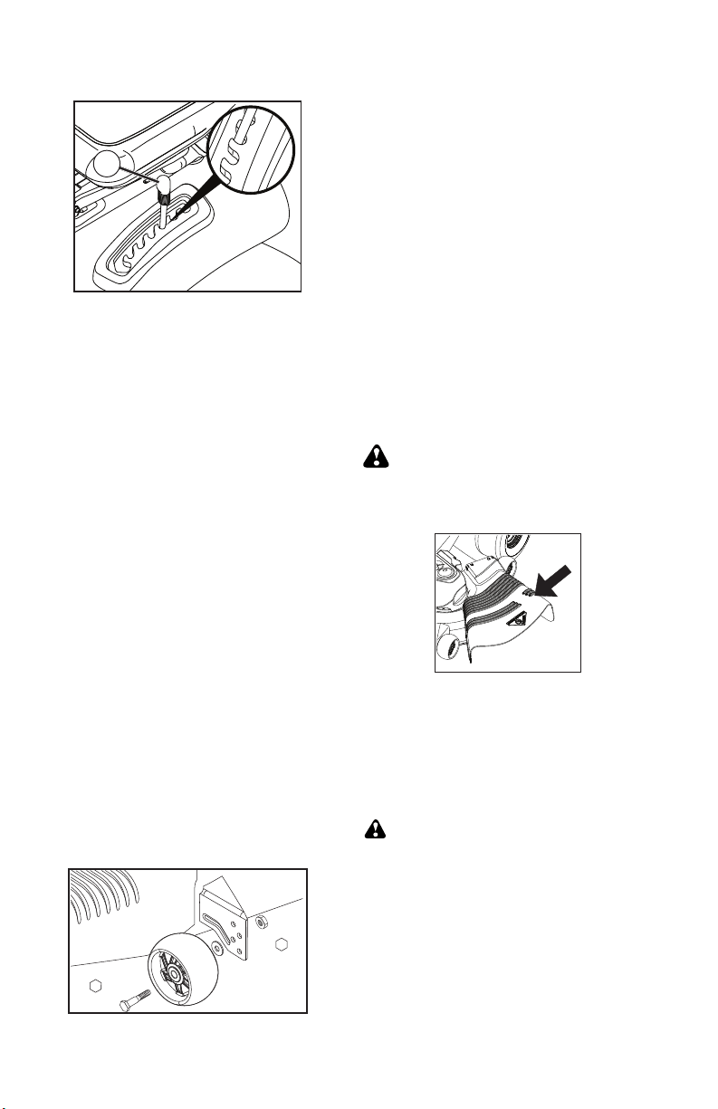
TO ADJUST GAUGE WHEELS
Gauge wheels are prop er ly ad just ed when
they are slight ly off the ground when mower
is at the desired cutting height in operating
position. Gauge wheels then keep the deck
in proper position to help prevent scalping
in most terrain conditions.
NOTE: Adjust gauge wheels with tractor on
a flat level surface.
1. Adjust mower to desired cutting height
(See “TO AD JUST MOWER CUT TING
HEIGHT” in this sec tion of manual).
A
3/4”
9/16”
TO OPERATE MOWER
Your tractor is equipped with an operator
presence sensing switch. Any attempt
by the operator to leave the seat with the
engine running and the attachment clutch
engaged will shut off the engine. You must
remain fully and centrally positioned in the
seat to prevent the engine from hesitating or
cutting off when operating your equipment
on rough, rolling terrain or hills.
1. Select desired height of cut with attach-
ment lift lever.
2. Start mower blades by engaging at tach-
ment clutch control.
TO STOP MOWER BLADES
Disengage at tach ment clutch con trol.
CAUTION: Do not operate the mower
without either the en tire grass catcher, on
mowers so equipped, or the deflector shield
in place.
TO ADJUST MOWER CUT TING HEIGHT
The po si tion of the at tach ment lift le ver (A)
de ter mines the cut ting height.
• Put attachment lift lever in desired cutting
height slot.
The cutting height range is ap prox i mate ly 1
to 4" (25,4 to 101,6 mm). The heights are
measured from the ground to the blade tip
with the engine not running. These heights
are approximate and may vary depending
upon soil conditions, height of grass and
types of grass being mowed.
• The average lawn should be cut to approxi-
mately 2-1/2" (63,5 mm) during the cool
season and to over 3" (76,2 mm) during
hot months. For healthier and better look-
ing lawns, mow often and after moderate
growth.
• For best cutting performance, grass over
6" (152,4 mm) in height should be mowed
twice. Make the first cut relatively high; the
second to de sired height.
2. With mower in desired height of cut po si-
tion, gauge wheels should be assembled
so they are slightly off the ground. In stall
gauge wheel in ap pro pri ate hole. Tighten
se cure ly.
3. Repeat for all, installing gauge wheel in
same adjustment hole.
REVERSE OPERATION SYSTEM (ROS)
Your tractor is equipped with a Reverse
Operation System (ROS). Any attempt by
the operator to travel in the reverse direction
with the attachment clutch engaged will shut
off the engine unless ignition key is placed
in the ROS "ON" position.
WARNING: Backing up with the at-
tachment clutch engaged while mowing is
strongly discouraged. Turning the ROS "ON",
to allow reverse operation with the attach-
ment clutch engaged, should only be done
when the operator decides it is necessary to
reposition the machine with the attachment
engaged. Do not mow in reverse unless
absolutely necessary.
53
E
F
H
J
C
D
M
Q
E
B
D
P
F
L
K
H
A
M
R
D
C
C
A
B
IMPORTANTE: VERIFIQUE QUE LA CORREA
ENCAJE BIEN EN TODAS LAS RANURAS DE
LAS POLEAS DE LA CORTADORA.
12. Suba la palanca elevadora a la posición de
más arriba.
13. Si es necesario, ajuste las rueditas del calibre
antes de poner en funcionamiento la corta-
dora, como se ilustra en el capítulo de Manejo
de este manual.
9. Conecte el fin de la primavera de cable de
embrague (Q) en el orificio de holgazán (R).
10. Retire el resorte de sujeción (K), deslice la
abrazadera (L) hasta quitarla, y saque a pre-
sión la guía de la caja (P) hasta que se salga
del soporte.
11. Instale la correa pasándola por encima de la
polea del motor (M)
7. CONECTE LA CONEXION ANTERIOR (E) -
Trabajo del dejó el lado de tractor. Meta el fin
de la barra de la asamblea de la conexión por
orificio anterior en el tractor suporte anterior
de suspensión (F).
8. Meta el fin de la conexión (E) en el hoyo en
el suporte anterior de orificio y conecte con
arandela e Retén del resorte (J).
5. FIJE LAS PIEZAS DE PROPULSIÓN POS-
TERIORES (C) – Levante la parte posterior
de la cortadora, ubique la ranura de la pieza
de unión (D) por encima de la clavija que hay
en la barra posterior de la cortadora y fíjela
con una arandela y un resorte de contención.
6. Realice el mismo procedimiento en el otro
lado del tractor.
4. Realice el mismo procedimiento en el otro
lado del tractor.
Loading ...
Loading ...
Loading ...