®
MODELNUMBER 917.258553
o Assembly
o Operation
o Customer Responsibilities
Service and Adjustments
o Repair Parts
OWNER'S MANUAL
CAUTION: Read and follow all safety rules and instructions before operating this equipment.
FOR CONSUMER ASSISTANCE HOT LINE, CALL THIS TOLL FREE NUMBER: 1-800-659-5917
_- IIIIIIIII

SAFETY RULES
Safe Operation Practices for Ride-On Mowers
IMPORTANT: THIS CUTT_NG MACHINE IS CAPABLE OF AMPUTATING HANDS AND FEET AND THROWING OBJECTS°
FAILURE TO OBSERVE THE FOLLOWING SAFETY INSTRUCTIONS COULD RESULT IN SERIOUS iNJURY OR DEATH
I*
I
,e
Q
GENERAL OPERATION
Read, understand, and follow all instructions in the manual
and on the machine before starting.
Only allow responsible adults, who are familiar with the
instructions, to operate the machine
Clear the area of objects such as rocks, toys, wire, etc,
which could be picked up and thrown by the blade.
Be surethe area is clear of other people before mowing Stop
machine if anyone enters the area
Never carry passengers.
Do not mow in reverse uniess absolutely necessary Nways
look down and behind before and while backing
Be aware of the mower discharge direction and do not point
it at anyone.. Do not operate the mower without either the
entire grass catcher or the guard in place.
Slow down before turning.
Never leave a running machine unattended Always turn off
blades, set parking brake, stop engine, and remove keys
before dismounting.
Turn off blades when not mowing.
Stop engine before removing grass catcher or unclogging
chute
Mow only in daylight or good artificial light..
Do not operate the machine while under the influence of
alcohol or drugs.
Watch for traffic when operating near or crossing roadways.
Use extra care when loading or unloading the machine into
a trailer or truck.
11. SLOPE OPERATION
Slopes are a major factor related to loss-of-control and
tipover accidents, which can result in severe injury ordeath.,
All slopes require extra caution, tf you cannot back up the
slope or if you feel uneasy on it, do not mow it.
DO:
• Mow up and down slopes, not across
• Remove obstacles such as rocks, tree limbs, etc.
• Watch for holes, ruts, or bumps Uneven terrain could
overturn the machine Taft grass can hide obstacles.
• Use slow speed. Choose a tow gear so that you wil! not have
to stop or shift while on the slope.
• Follow the manufacturer's recommendations for wheel
weights or counterweights to improve stability°
• Use extra care with grass catchers or other attachments
These can change the stability of the machine.
• Keep all movement on the slopes slow and gradual Do not
make sudden changes in speed or direction
° Avoid starting or stopping on a stope, if tires [ose traction,
disengage the biades and proceed slowly straight down the
slope,
DO NOT:
• Donot turn on slopes unless necessary, and then, turn siowly
and gradually downhill, if possible.
• Do not mow near drop-offs, ditches, or embankments. The
mower could suddenly turn over if a wheel is over the edge
of a cliff or ditch, or il an edge caves in.
• Do not mow on wet grass Reduced traction coutd cause
sliding.
• Do not try to stabilize the machine by putting your foot on the
ground
• Do not use grass catcher on steep slopes
tii. CHILDREN
Tragic accidents can occur if the operator is not alert to the
presence of children.. Children are often attracted to the
machine and the mowing activity. Never assume that
children wilt remain where you last saw them.
• Keep children out of the mowing area and under the watchful
care of another responsible adult.
• Be alert an_ tUi'nmachine off if children ent_Ftfle area.
• Before and when backing, look behind and down for small
children
• Never carry children. They may fail off and be seriously
injured or interfere with sale machine operation.
• Never allow children to operate the machine.
• Use extra care when approaching blind corners, shrubs,
trees, or other objects that may obscure vision.
IV. SERVICE
• Use extra care in handling gasoline and other fuels. They are
flammable and vapors are explosive.
Use only an approved container
Never remove gas cap or add fuel with the engine
running Allow engine to cool before refueling.. Do not
smoke.
Never refuel the machine indoors.
Never store the machine or fuel container inside where
there is an open flame, such as a water heater.
• Never run a machine inside a closed area
,, Keep nuts and bolts, especially blade attachment boits, tight
and keep equipment in good condition..
• Never tamper with safety devices. Check their proper
operation regularly.
. Keep machine free of grass, leaves, or other debris build-up.
Clean oif or fuel spillage Aliow machine to cool before
storing
. Stop and inspect the equipment if you strike an object
Repair, if necessary, before restarting
• Never make adjustments or repairs with the engine running.
• Grass catcher components are subject to wear, damage, and
deterioration, which coufd expose moving parts or allow
objects to be thrown. Frequently check components and
replace with manufacturer's recommended parts, when nec_
essary.
• Mower blades are sharp and can cut Wrap the blade(s) or
wear gloves, and use extra caution when servicing them..
• Check brake operation frequently. Adjust and service as
required
Look for this symbol to point out im-
portant safety precautions. It means
CAUTIONt_I BECOMEALERT!!! YOUR
SAFETY IS INVOLVED.
= HHHHH H'=H'H
CAUTION: Always disconnect spark plug
wire and plac e wire where it cannot contact
spark plug in order to prevent accidental
starting when setting up, transporting,
adjusting or making repairs.
" A WARNING A
The engine exhaust from this product con-
tains chemicals known to the State of Califor-
nia to cause cancer, birth defects, or other
reproductive harm.
= H ::::::::::::::::::::::::

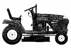
CONGRATULATIONS on your purchase of a Sears
Tractor° It has been designed, engineered and manufac-
tured to give you the best possible dependability and
performance°
Should you experience any problem you cannot easily
remedy, please contact your nearest Sears Authorized
Service CentedDepartmenL We have competent, well-
trained technicians and the proper tools to service or repair
this tractor..
Please read and retain this manual. The instructions will
enable you to assemble and maintain your tractor properly.
Always observe the "SAFETY RULES".
MODEL
NUMBER
SERIAL
NUMBER
9174258553
DATE OF PURCHASE
THEMODELANDSERIALNUMBERSWILLBEFOUND
ON A PLATE UNDER THE SEAT.
YOUSHOULDRECORDBOTHSERIALNUMBERAND
DATE OFPURCHASEAND KEEPtN A SAFE PLACE
FOR FUTURE REFERENCE.
PRODUCT SPECiFICATaONS
HORSEPOWER: 15.0
GASOLINE CAPACITY 125 GALLONS
OIL TYPE (API-SF/SG/SH): SAE 10W30 (above 32°F)
SAE 5W-30 (below 32°F)
elL CAPACITY: W! FlLTER: 4°0 PINTS
W/O FILTER: 35 PINTS
SPARK PLUG: CHAMPION RC12YC
(GAP: °040")
.=
VALVE CLEARANCE:
GROUND SPEED (MPH):
NOT ADJUSTABLE
FORWARD: 0- 5.5
REVERSE: 0-2.4
TIRE PRESSURE: FRONT: 14 PSI
REAR: 10 PSI
C,HARGING SYSTEM: 3 AMPS BATTERY
5 AMPS HEADLIGHTS
BATTERY: AMP/HR: 30
MIN. CCA: 240
CASE SIZE: UIR
BLADE BOLT TORQUE: 30-35 FT. LBS.
AND TYPE: UNLEADED REGULAR
MAINTENANCE AGREEMENT
A Sears Maintenance Agreement is available on this prod-
uct. Contact your nearest Sears store for details.
CUSTOMER RESPONSIBILITIES
• Read and observe the safety rules.
• Follow a regular schedule in maintaining, caring for and
using your tractor°
• Follow the instructions under "Customer Responsibili-
ties" and "Storage" sections of this owner's manual.
WARNING: This tractor is equipped with an internal
combustion engine and should not be used on or near any
unimproved forest-covered, brush-covered or grass-cov-
ered land unless the engine's exhaust system is equipped
with a spark arrester meeting applicable local or state laws
(if any). If a spark arrester is used, it should be maintained
in effective working order by the operator.
In the state of California the above is required by law
(Section 4442 of the California Public Resources Code)°
Other states may have similar laws. Federal laws apply on
federa_ lands. A spark arrester for the muffler is available
through your nearest Sears Authorized Service Center/
Department (See REPAIR PARTS section of this manual).
r."l='l"l'.' i'1' i1,11 ............. = . ..,H.I.,,
LIMITED TWO YEAR WARRANTY ON CRAFTSMAN RIDING EQUIPMENT
For two (2) years from the date of purchase, if this Craftsman Riding Equipment is maintained, lubricated and tuned up according
to the instructions in the owner's manual, Sears will repair or replace, free of charge, any parts found to be defective in material or
workmanship.
This Warranty does not cover:.
• Expendable items which become worn during normal use, such as blades, spark plugs, air cleaners, belts, etc
• Tire replacement or repair caused by punctures from outside objects, such as nails, thorns, stumps, or glass,
• Repairs necessary because of operator abuse, negligence, improper storage or accident or the failure to maintain the
equipment according to the instructions contained in the owner's manual.
• Riding equipment used for commercial or rental purposes.
LIMITED 90 DAY WARRANTY ON BATTERY
For ninety (90) days from _at_6f pi]i-_ha_e_ if any battery inctudeclwith th_s riding eqtJil_rne-nt_p?ovesdeflective in r:nateriai or
workmanship and ou_ testing determines the battery will not hold a charge, Sears will replace the battery at no charge°
IN-HOME WARRANTY SERVICE ON YOUR CRAFTSMAN RIDING EQUIPMENT IS AVAILABLE AT NO-CHARGE FOR 30
DAYS FROM THE DATE OF PURCHASE.. PLEASE CONTACT YOUR NEAREST SERVICE CENTER AFTER 30 DAYS FROM
THE DATE OF PURCHASE, WARRANTY SERVICE IS AVAILABLE BY TAKING YOUR CRAFTSMAN RIDING EQUIPMENT TO
YOUR NEAREST SEARS SERVICE CENTER. (IN-HOME WARRANTY SERVICE WILL STILL BE AVAILABLE AFTER 30 DAYS
FROM THE DATE OF PURCHASE BUT A STANDARD TRiP CHARGE WILL APPLY.) THIS WARRANTY APPLIES ONLY
WHILE THIS PRODUCT IS IN THE UNITED STATES.
This Warranty gives you specific legal rights, and you may also have other rights which may vary from state to state°
SEARS, ROEBUCK AND CO., D/817 WA, HOFFMAN ESTATES, IL 60179
........... i. , ,.....,., ....................
3
TABLE OF CONTENTS
SAFETY RULES ............................................................ 2
PRODUCT SPECIFICATIONS ...................................... 3
CUSTOMER RESPONSIBILITIES ..................... 3, 16-19
WARRANTY .................................................................. 3
TABLE OF CONTENTS ................................................ 4
INDEX .................................. ;......................................... 4
TRACTOR ACCESSORIES .......................................... 5
ASSEMBLY ................................................................ 7-9
OPERATION ........................................................... 10-15
MAINTENANCE SCHEDULE ...................................... 16
SERVICE AND ADJUSTMENTS ............................ 20-25
STORAGE ................................................................... 26
TROUBLESHOOTING ............................................ 27-28
REPAIR PARTS - TRACTOR ................................. 30-47
REPAIR PARTS - ENGINE .................................... 48-53
PARTS ORDERING/SERVICE .................. BACK PAGE
INDEX
A
Accessories ....................................................5
Adjustments:
Brake ......................................................22
Carburetor
............................................
25
Mower:
Front-To-Back ........................... 21
Side-To-Side .................................21
Throttle Control Cable .....................24
Air Filter, Engine ........................................18
Air Screen, Engine .............................. 18
Assembly ................................................ 7-9
B
Battery:
Charging ........................................... 7-8
Cleaning .......................................... 17
Connecting ......................................7-8
Starting with Weak Battery .............23
Storage .................................................26
Terminals ...........................................17
Belts:
Motion Drive
Remova!/Replacement ............ 22
Mower Blade Drive
Removal/Replacement ............ 22
Blade:
Sharpening ..................................... 17
Replacement .........................................17
Brake Adjustment ................................ 22
C
Carburetor Adjustment ...........................25
ContreIs, Tractor ................................ 11
Customer Responsibilities .............. 16.19
Engine:
Air Filter ......................................... 1 8
Air Screen, Engine .................. 19
Battery .......................................... 17
Cooling Fins, Engine ................ 19
Engine Oil ................................. 19
Fuel Filter .................................... 19
Spark Plugs ............................... 19
Tractor:
Blades ..................................... 17
Lubrication Chart ..................... 16
Maintenance Schedule ........... t6
Tire Care ......:...................... 8,17,23
Cutting Height, Mower .............................12
E
Electrical:
Interlocks and Relays ........................24
Schematic ...................................... 29
Wiring Diagram .............................. 30
Engine:
Air Filter ........................................... 18
Air Screen ....................................... 19
Cooling Fins, Engine .................... !9
Oil Change .........................................18
Oil Level ........................................13,18
Oil Type ...............................................18
Preparation .........................................13
Repair Parts ...............................48-53
Starting ........................................... 14
Storage ............................................28
F
Fil{ers:
Air ...................................................... 18
Fuel ...................................................19
Fuel:
Type ...................................................13
Storage .................................................26
Fuse .................................................................24
G
Gauge Wheels ........................................ 8
H
Hood Removal/Installation ................... 24
L
Leveling Mower Deck .............................21
Lubrication Chart .................................... 16
M
Maintenance Schedule ...................... 16
Mower:
Adjustment, Front-to-Back ..............2t
Adjustment, Side-to-Side ...............21
Blade Sharpening ................................ 17
Blade Replacement ............................17
Cutting Height ..................................._,,12
Installation ...........................................20
Operation .... ,.:..;...,.......:,°..::,..oo;:...13
Removal ......................................... 20
Mowing Tips ..............................................15
Muffler .......................................................19
Spark Arrestor .......................... 3,40
Mulcher Plate .......................................... 9
O
Oil:
Cold Weather Conditions ....... 13,18
Engine .......................................................18
Storage ........................................................... 26
Operation ......................................... 1O-t 5
Operating Mower ........................................ 13
Options:
Accessories ............................................5
Spark Arrester ..................................3,40
P
Parking Brake .........................................11-12
Parts Bag .........................................................6
Parts, Replacement/Repair ...............30-47
Product Specifications ............................... 3
R
Repair Parts ................................... 30-47
S
Safety Rules ............................................... 2
Seat ....................................................................... 8
Service and Adjustments ..................20-25
Brake ....................................................22
Carburetor ..........................................25
Fuse .........................................................24
Hood Removal/Installation ..................24
Motion Drive Belt
Removal/Replacement ........... 22
Mower Blade Drive Belt
Removal/Replacement ..............22
Mower Adjustment:
Front-to-Back ..............................21
Side4o*Side .................................21
Mower Installation .................................20
Mower Removal .............................. 20
Tire Care ..................................8,17,23
Slope Guide Sheet ..................................55
Spark Plugs .............................................. 19
Specifications ................................................3
Starting the Engine ........................ 13-14
Steering Wheel ......................................7,23
Stopping the Tractor ................................12
Storage ...........................................................26
T
Throttle Control Cable Adjustment ..... 24
Tires .............................................. 8,17,23
Trouble Shooting Chart ....................27-28
Transaxle Repair Parts .................. 46-47
W
Warranty .......................................................3
Wiring Diagram ............................................30
Wiring Schematic .......................................29
H iii1,1i i ..................... I,,IL,,Ii ........ " ,i i,i
ACCESSORIES AND ATTACHMENTS
iiiii ........................... i, i ,i IINIIH,II ...................................
These accessories and attachments were available through most Sears retail outletsand service centers when the tractorwas purchased,
Most Sears stores can order these items for you when you provide the model number of your tractor.
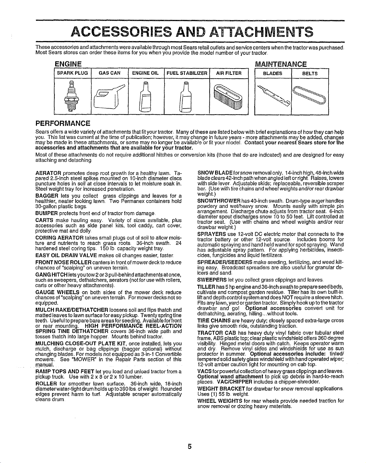
ENGINE MAINTENANCE
SPARK PLUG BLADES BELTSGAS CAN ENGINE OIL FUEL STABILIZER AIR FILTER
%
PERFORMANCE
Sears offers a wide vadety of attachments that fit your tractor_ Many of these are listed below with bdef explanations of how they can help
you. This list was current at the time of publication; however, it may change in future years - more attachments may be added changes
may be made in these attachments, or some may no longer be availab_'e or fit your model. Contact your nearest Sears store for the
accessories and attachments that are available for your tractor.
Most of these attachments do not require additional hitches or conversion kits (those that do are indicated) and are designed for easy
attaching and detaching
AERATOR promotes deep root growth for a healthy lawno Ta-
pered 2.5-inch steel spikes mounted on 10-inch diameter discs
puncture holes in soil at ciose intervals to let moisture soak in.
Steel weight tray for increased penetration.
BAGGER lets you collect grass clippings and leaves for a
healthier, heater looking lawn. Two Permanex containers hold
30-gallon plastic bags
BUMPER protects front end of tractor from damage
CARTS make hauling easy. Variety of sizes available, plus
accessories 'such as side panel kits, tool caddy, cart cover,
protective mat and dolly,
CORING AERATOR takes small plugs out of soit to aitow mois-
ture and nutrients to reach grass roots, 36-inch swath. 24
hardened steel coring tips. 150 Ib capacity weight tray_
EASY OIL DRAIN VALVE makes oil changes easier, faster.
FRONT NOSE ROLLER canters infront of mower deck to reduce
chances of "scalping" on uneven terrain,
GANG HITCH iets you tow 2 or 3 pull-behind attachments at once,
such as sweepers, dethatchers, aerators (not for use with rollers,
carts or other heavy attachments),
GAUGE WHEELS on both sides of the mower deck reduce
chances of "scalping" on uneven terrain_ For mower decks not so
equipped.
MULCH RAKE/DETHATCHER loosens soil and flips thatch and
matted leaves to lawn surface for easy pickup. Twenty spring line
teeth, Useful to prepare bare areas for seeding. Available for front
or rear mounting, HIGH PERFORMANCE REEL-ACTION
SPRING TINE DETHATCHER covers 36-inch wide path and
tosses thatch into large hopper. Mounts behind tractor,
MULCHING CLOSE-OUT PLATE KIT, once installed, lets you
mulch, discharge or bag clippings (bagger optional) without
changing b_ades_For models not equipped as 3-in-1 Convertible
mowers See "MOWER" in the Repair Parts section of this
!_ anua!_
RAMP TOPS AND FEET Iet you load and unload tractor from a
pickup truck° Use with 2 x 8 or2 x 10 lumber.
ROLLER for smoother lawn surface, 36-inch wide, 18-inch
diameterwater-tightdrum holds upto3g01bs, ofweighL Rounded
edges prevent harm to turf. Adjustable scraper automatically
deans drum
SNOW BLADEforsnowremovalonly. 14-inch high,48-inchwide
blade clears 42-inch path when angted left or right. Raises, lowers
with side {ever Adjustable skids; replaceable, reversible scraper
bar. (Use with tire chains and wheet weights and/or rear drawbar
weight.,)
SNOWTHROWER has 40-inch swath. Drum-type auger handles
powdery and wet/heavy snow., Mounts easily with simple pin
arrangement. Discharge chute adjusts from tractor seat° 6_inch
diameter spout discharges snow 10 to 50 feet. Lift controlled at
tractor seat. (Use with chains and wheel weights and/or rear
drawbar weight,)
SPRAYERS use 12-vo_t DC electric motor that connects to the
tractor battery or other 12-volt source Includes booms for
automatic spraying and hand held wand for spot spraying. Wand
has adjustable spray pattern,, For applying herbicides, insecti-
cides, fungicides and liquid fertilizers,
SPREADEPJSEEDERS make seeding, fertilizing, and weed kill-
ing easy. Broadcast spreaders are also useful for granular de-
icers and sand_
SWEEPERS Iet you collect grass clippings and leaves.
TILLER has 5 hp engine and 36-inch swath toprepare seed beds,
cuItivate and compost garden residue. Tiller has its own built-in
liftand depth control system and does NOT require a sleeve hitch.
Fits any lawn, yard or garden tractor, Simply hook up to the tractor
drawbar and go! Optional accessories convert unit for
dethatching, aerating, hilling.. ,without tools.
TIRE CHAINS are heavy duty; closely spaced extra-large cross
links give smooth ride, outstanding traction.
TRACTOR CAB has heavy duty vinyl fabric over tubular steel
frame, ABS plastic top; clear plastic windshield offers 360 degree
visibility, Hinged metal doors with catch. Keeps operator warm
and dry. Remove vinyl sides and windshields for use as sun
protector in summer, Optional accessories include: tinted/
tempered solid safety glass windshield with hand operated wiper;
12-volt amber caution light for mounting on cab top.
VACS for powerfulcollection of heavy grass clippings and leaves.
Optional wand attachment to pick up debris in hard-to-reach
places,, VAC/CHIPPER inctudes a chipper-shredder.
WEIGHT BRACKET for drawbar for snow removal applications,
Uses (1) 55 lb_ weight,,
WHEEL WEIGHTS for rear wheels provide needed traction for
snow removal or dozing heavy materials.
ii = i
CONTENTS OF HA
PACK
lu,
, , iiiiiil,l,l,,u ii i,u,i
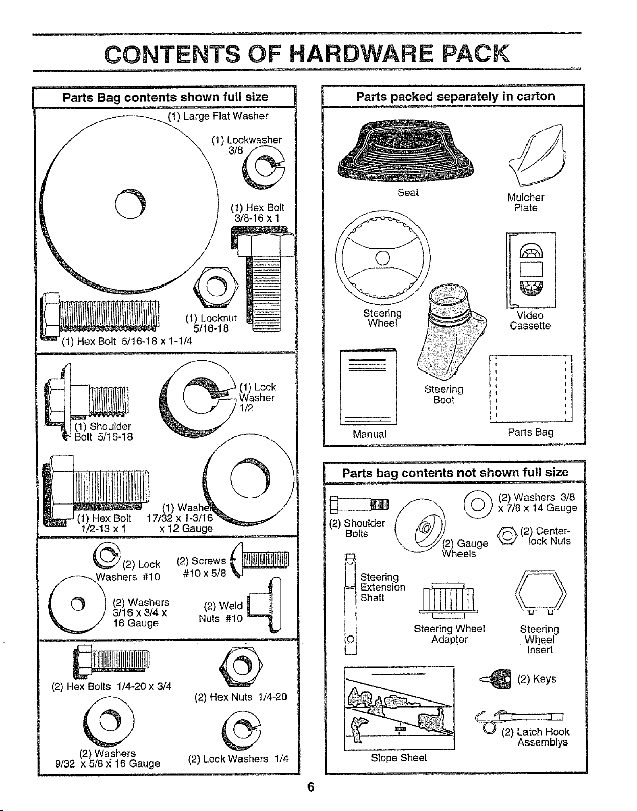
Parts Bag contents shown full size
ii ,,11,111.... i i , i ,, iii
(t) Large Flat Washer
(1) Lockwasher
O (!) Hex Bolt
3/8-16 x 1
Shoulder
5/16-'18
(1) Lock
Washer
1/2
(I)
(I) Hex Bolt 17132 x 1-3116
I12-13x I x 12 Gauge
iii llUl, i i Ul
_ (2) Lock (2) Screws _
Washers #10 #10 x 518
(q
(2) Weld _-_1
(2)
Washers
3/16 x 3/4 x
16 Gauge Nuts #10
-=qj
' iii
(2) Hex Bolts 1/4-20 x 3/4
@
(2) Washers
9132 x 518 x 16 Gauge
(2) Hex Nuts !/4-20
®
{2) kockWashers 1/4
i ii,u,, u ......
i ,u i,,,u,,,,,u
Parts packed separately in carton
Seat
Mulcher
Plate
Steering
Wheel
Manual
Vide_ °
Cassette
Steering I',
Boot
Parts Bag
iii u ii ....
Parts bag contents not shown full size
lu,
@2)h2e _ (2) Washers 3/8
(_ x 7t8 x 14 Gauge
(2) Shoulder
Bolts _ (2) Center-
uge x_ lock Nuts
I Steering _
Extension
Shaft
Steering Wheel Steering
Adapter Wheel
Insert
(2) Keys
Slope Sheet
Assemblys
6
ASSEMBLY
Your new tractor has been assembled at the factory with exception of those parts left unassembled for shipping purposes,
To ensure safe and proper operation of your tractor all parts and hardware you assemble must be tightened securely° Use
the correct tools as necessary to insure proper tightness.
TOOLS REQUIRED FOR ASSEMBLY
A socket wrench set will make assembly easier. Standard
wrench sizes are listed.
(t) 9/t6" wrench Utility knife
(2) 7/16" wrenches Phillips Screwdriver
(2) t/2" wrenches Tire pressure gauge
(1) 3/4" Socket w/drive rachet
When right or left hand is mentioned in this manual, it
means when you are in the operating position (seated
behind the steering wheel)..
TO REMOVE TRACTOR FROM CARTON
UNPACK CARTON
° Remove all accessible loose parts and parts cartons
from carton (See page 6).
, Cut, from top to bottom, along lines on all four corners
of carton, and lay panels flat.
= Check for any additional loose parts or cartons and
remove,
BEFORE ROLLING TRACTOR OFF SKID
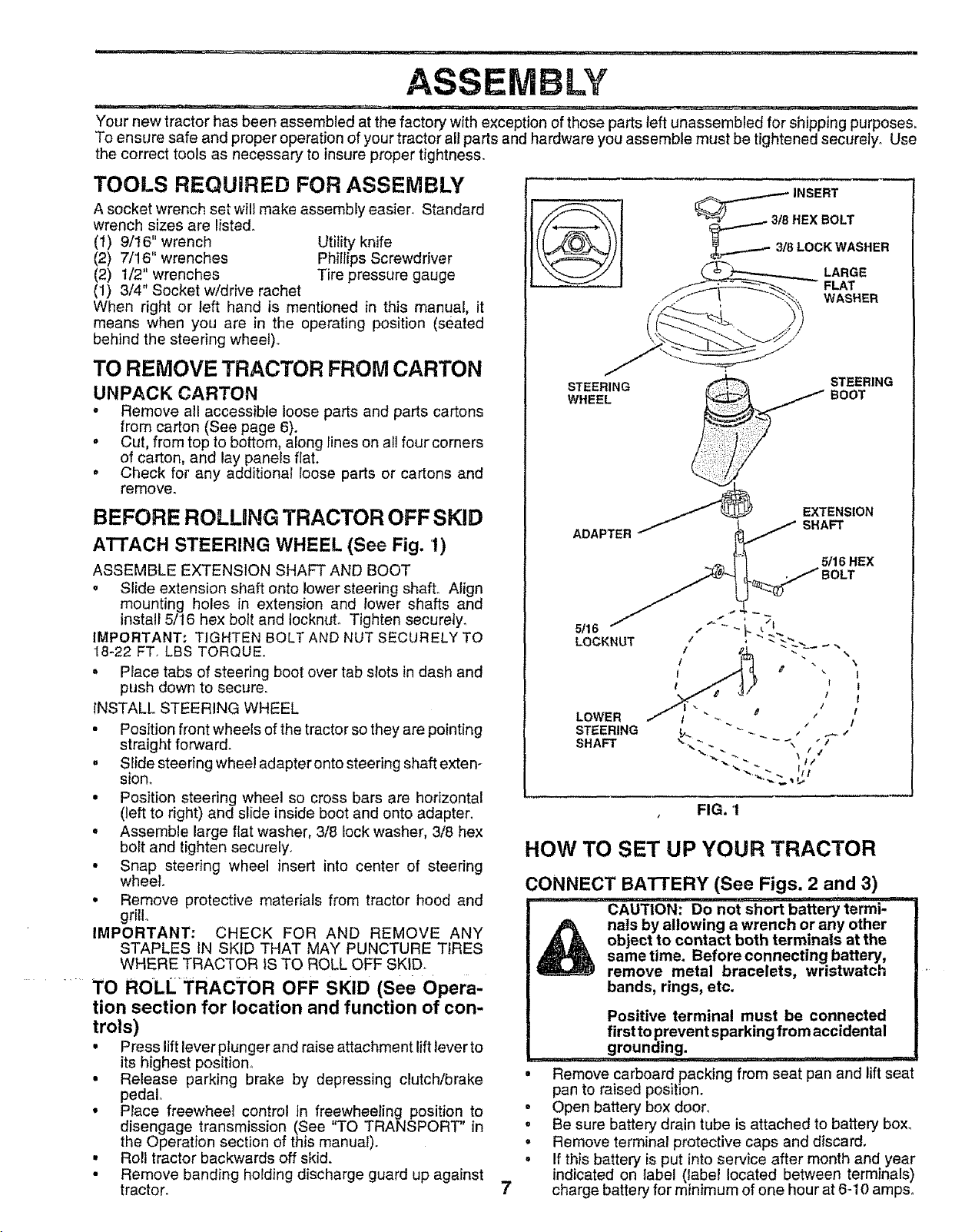
A'I-rACH STEERING WHEEL (See Fig. 1)
ASSEMBLE EXTENSION SHAFT AND BOOT
• Slide extension shaft onto lower steering shaft. Align
mounting holes in extension and lower shafts and
install 5/I6 hex bolt and locknut. Tighten securely.
IMPORTANT: TIGHTEN BOLT AND NUT SECURELY TO
18-22 FT. LBS TORQUE..
= Place tabs of steering boot over tab slots in dash and
push down to secure.
INSTALL STEERING WHEEL
• Position front wheels of the tractor so they are pointing
straight forward_
= Slide steering wheel adapter onto steering shaft exten-
sion.
• Position steering wheel so cross bars are horizontal
(left to right) and slide inside boot and onto adapter,
° Assemble large flat washer, 3/8 lock washer, 3/8 hex
bolt and tighten securely,
• Snap steering wheel insert into center of steering
wheel
• Remove protective materials from tractor hood and
grill,
IMPORTANT: CHECK FOR AND REMOVE ANY
STAPLES IN SKID THAT MAY PUNCTURE TIRES
WHERE TRACTOR IS TO ROLL OFF SKID_
TO ROLL_FRAC_rOR OFF SKID (See Opera-
tion section for location and function of con-
trols)
• Press lift lever plunger and raise attachment liftlover to
its highest position,,
• Release parking brake by depressing clutch/brake
pedal
• Place freewheel control in freewheeling position to
disengage transmission (See "TO TRANSPORT' in
the Operation section of this manua0.
• Roll tractor backwards off skid.
• Remove banding holding discharge guard up against
tractor.
_........ 3/8 REX BOLT
_.......--_ 3/8 LOCK WASHER
LARGE
FLAT
WASHER
STEERING
WHEEL
STEERING
BOOT
ADAPTER
EXTENSION
SHAFT
5116HEX
7
, FIG. I
HOW TO SET UP YOUR TRACTOR
CONNECT BATTERY (See Figs. 2 and 3)
,i, i i,ii1,1,1,1111111 ,1111, .i.1[.i.,i,i1.111,, n
CAUTION: DO not short battery termi-
nals by allowing a wrench or any other
object to contact both terminals at the
same time. Before connecting battery,
remove metal bracelets, wristwatch
bands, rings, etc.
o
0
°
o
Positive terminal must be connected
first to prevent sparking from accidental
grounding. ........
Remove carboard packing from seat pan and lift seat
pan to raised positaono
Open battery box door,
Be sure battery drain tube is attached to battery box.
Remove terminal protective caps and discard,
If this battery is put into service after month and year
indicated on label (label located between terminals)
charge battery for minimum of one hour at 6-10 amp&
LY
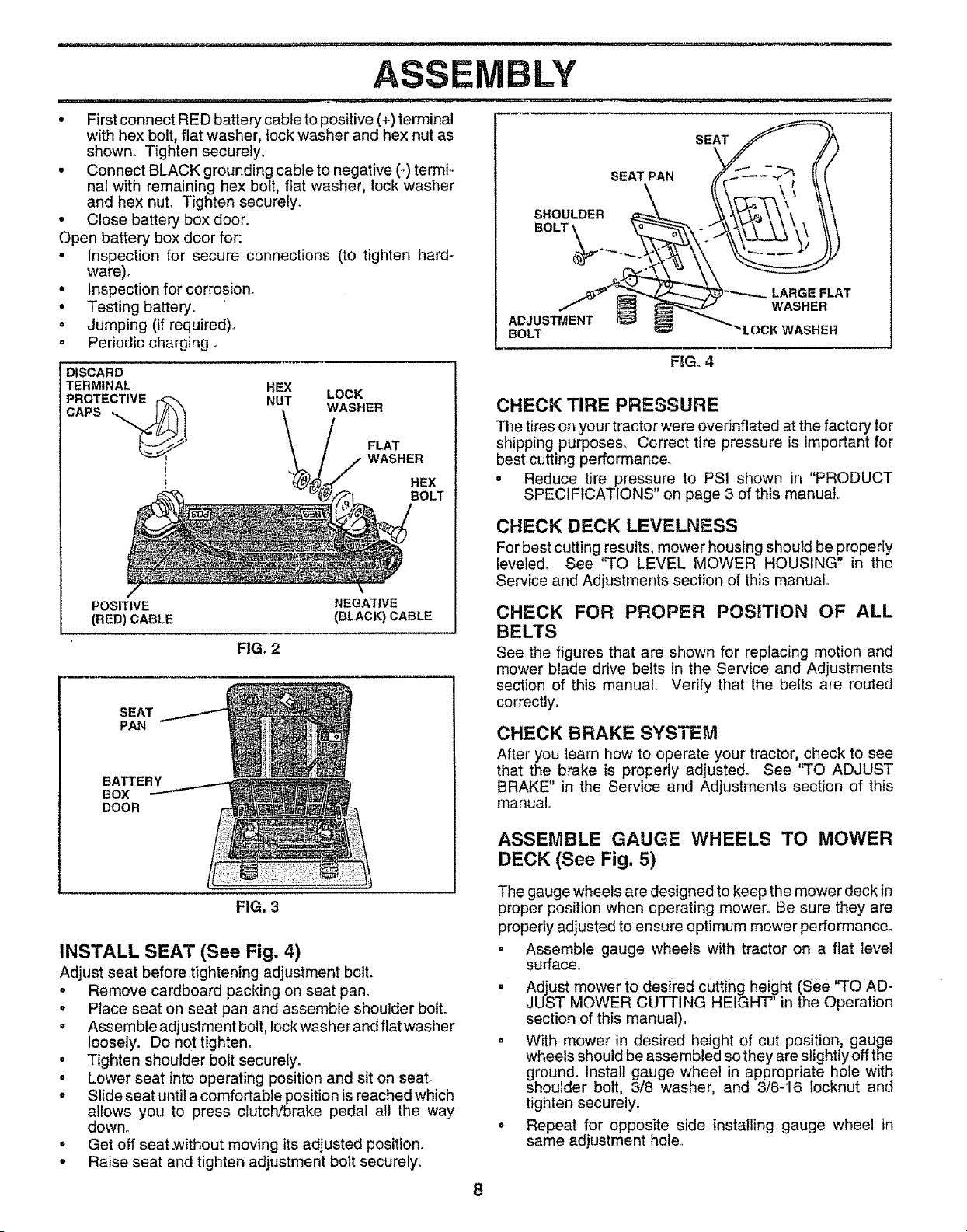
• First connect RED battery cable to positive (+) terminal
with hex bolt, flat washer, lock washer and hex nut as
shown. Tighten securely.
• Connect BLACK grounding cable to negative (-) termi..
nal with remaining hex bolt, flat washer, lock washer
and hex nut. Tighten securely.
• Close battery boxdoor.
Open battery box door for:
• Inspection for secure connections (to tighten hard-
SEAT PAN
SHOULDER
BOLT'
SEAT
ware).
• Inspection for corrosion.
• Testing battery.
• Jumping (if required).,
o Periodic charging o
DISCARD
TERMINAL
PROTECTIVE r_"_
HEX
NUT
LOCK
WASHER
FLAT
WASHER
HEX
BOLT
POSITIVE NEGATIVE
(RED) CABLE (BLACK) CABLE
FIG. 2
SEAT
PAN
BATTERY
BOX
DOOR
LARGE FLAT
WASHER
ADJUSTMENT
BOLT
RGo 4
CHECK TIRE PRESSURE
The tires on your tractor were ovednflated at the factory for
shipping purposes,, Correct tire pressure is important for
best cutting performance_
• Reduce tire pressure to PSI shown in "PRODUCT
SPECIFICATIONS" on page 3 of this manual
CHECK DECK LEVELNESS
For best cutting results, mower housing should be properly
leveled. See 'qO LEVEL MOWER HOUSING" in the
Service and Adjustments section of this manual.
CHECK FOR PROPER POSiTiON OF ALL
BELTS
See the figures that are shown for replacing motion and
mower blade drive belts in the Service and Adjustments
section of this manual. Verify that the belts are routed
correctly.
CHECK BRAKE SYSTEM
After you learn how to operate your tractor, check to see
that the brake is properly adjuste& See 'q'O ADJUST
BRAKE" in the Service and Adjustments section of this
manual,
ASSEMBLE GAUGE WHEELS TO MOWER
DECK (See Fig. 5)
FIG, 3
INSTALL SEAT (See Fig. 4)
Adjust seat before tightening adjustment bolt.
• Remove cardboard packing on seat pan.
, Place seat on seat pan and assemble shoulder bolt.
• Assembleadjustmentbolt, Iockwasherandflatwasher
loosely. Do not tighten.
• Tighten shoulder bolt securely_
o Lower seat into operating position and sit on seat_
• Slide seat until a comfortable position is reached which
allows you to press clutch/brake pedal all the way
down.
• Get off seat.without moving its adjusted position.
- Raise seat and tighten adjustment bolt securely.
The gauge wheels are designed to keep the mower deck in
proper position when operating mower, Be sure they are
properly adjusted to ensure optimum mower performance.
. Assemble gauge wheels with tractor on a flat levei
surface.
• Adjust mower to desi_'ed cutting height (See "TO AD-
JUST MOWER CUTTING HEIGHT" in the Operation
section of this manual).
• With mower in desired height of cut position, gauge
wheels should be assembled so they are slightly off the
ground. Install gauge wheel in appropriate hole with
shoulder bolt, 3/8 washer, and 3/8-16 locknut and
tighten securely.
• Repeat for opposite side installing gauge wheel in
same adjustment hole,
1,1,1,,, ,i,,11 ,= , .................. iii ii ii i .............
ASSEMBLY
TO CONVERT TO BAGGING OR
DISCHARGING
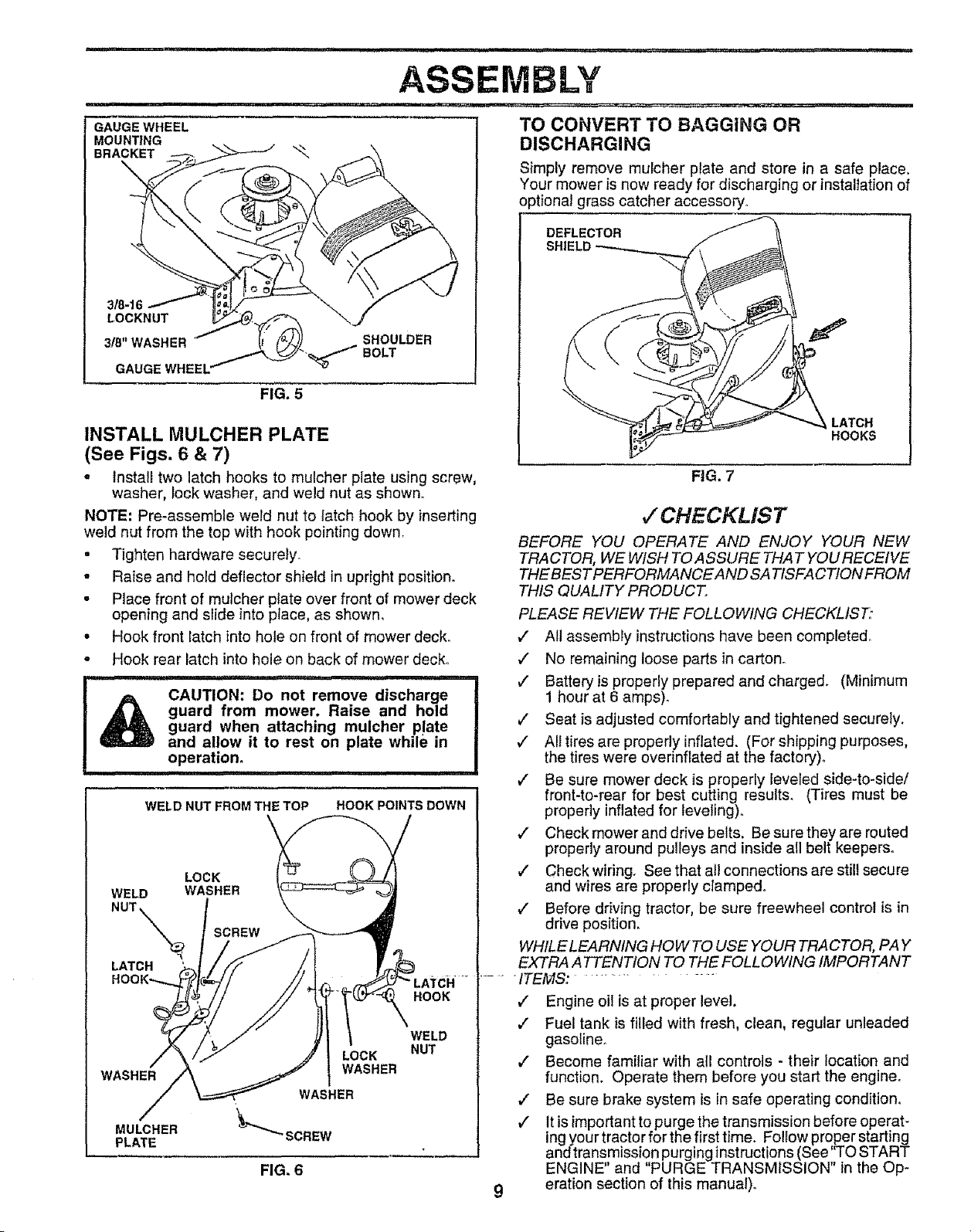
GAUGE WHEEL
MOUNTING
BRACKET
3_-16
LOCKNUT
3!8"WASHER
GAUGE WHEEL
FIG. 5
INSTALL MULCHER PLATE
(See Figs. 6 & 7)
SHOULDER
BOLT
Simply remove mulcher plate and store in a safe place,
Your mower is now ready for discharging or installation of
optional grass catcher accessory.
DEFLECTOR
SHIELD
LATCH
HOOKS
= Install two latch hooks to mulcher plate using screw,
washer, lock washer, and weld nut as shown.
NOTE; Pre-assemble weld nut to latch hook by inserting
weld nut from the top with hook pointing down.
- Tighten hardware securely.
= Raise and hold deflector shield in upright position.
- Place front of mulcher plate over front of mower deck
opening and slide into place, as shown,
• Hook front latch into hole on front of mower deck.
o Hook rear latch into hole on back of mower deck.
CAUTION: Do not remove discharge
guard from mower. Raise and hold
guard when attaching mulcher plate
and allow it to rest on plate while in
operation.
.............. IHI 'lip IpH ,
WELD NUT FROM THE TOP HOOK POINTS DOWN
FIG. 7
,/'CHECKLIST
BEFORE YOU OPERATE AND ENJOY YOUR NEW
TRACTOR, WE WISH TO ASSURE THAT YOU RECEIVE
THEBESTPERFORMANCEAND SA TISFACT!ON FROM
THIS QUALITY PRODUCT.
PLEASE REVIEW THE FOLLOWING CHECKLIST:
J" All assembly instructions have been completedo
,/ No remaining loose parts in carton_
,I Batteryis properly prepared and charged. (Minimum
1 hour at 6 amps)o
v" Seat is adjusted comfortably and tightened securely.
,/ All tires are properly inflated. (For shipping purposes,
the tires were overinfiated at the factory)°
,/ Be sure mower deck is properly leveled side-to-side/
front-to-rear for best cutting results. (Tires must be
properly inflated for leveling)°
v" Check mower and drive belts. Be sure they are routed
properly around pulleys and inside all belt keepers.
LOCK
WELD WASHER
NUT_x_ SCREW
LATCH
WASHER
MULCHER
PLATE
LOCK
WASHER
FIG. 6
HOOK
WELD
NUT
9
,/ Check wiring. See that all connections are still secure
and wires are properly c_ampedo
,/ Before driving tractor, be sure freewheel control is in
drive position_
WHILE LEARNING HOWTO USE YOUR TRACTOR, PAY
EXTRA A TTENTION TO THE FOLLOWING IMPORTANT
ITEMS: ...........
v" Engine oil is at proper level.
,/ Fuel tank is filled with fresh, clean, regular unleaded
gasoline.
,/ Become familiar with all controls - their location and
function. Operate them before you start the engine.
v" Be sure brake system is in safe operating condition.
,/ It is important to purge the transmission before operat-
ing your tractor for the first time. Follow proper starting
and transmission purging instructions (See'q_O START
ENGINE" and "PURGE TRANSMISSION" in the Op-
eration section of this manual).
ml,,
OPERATION
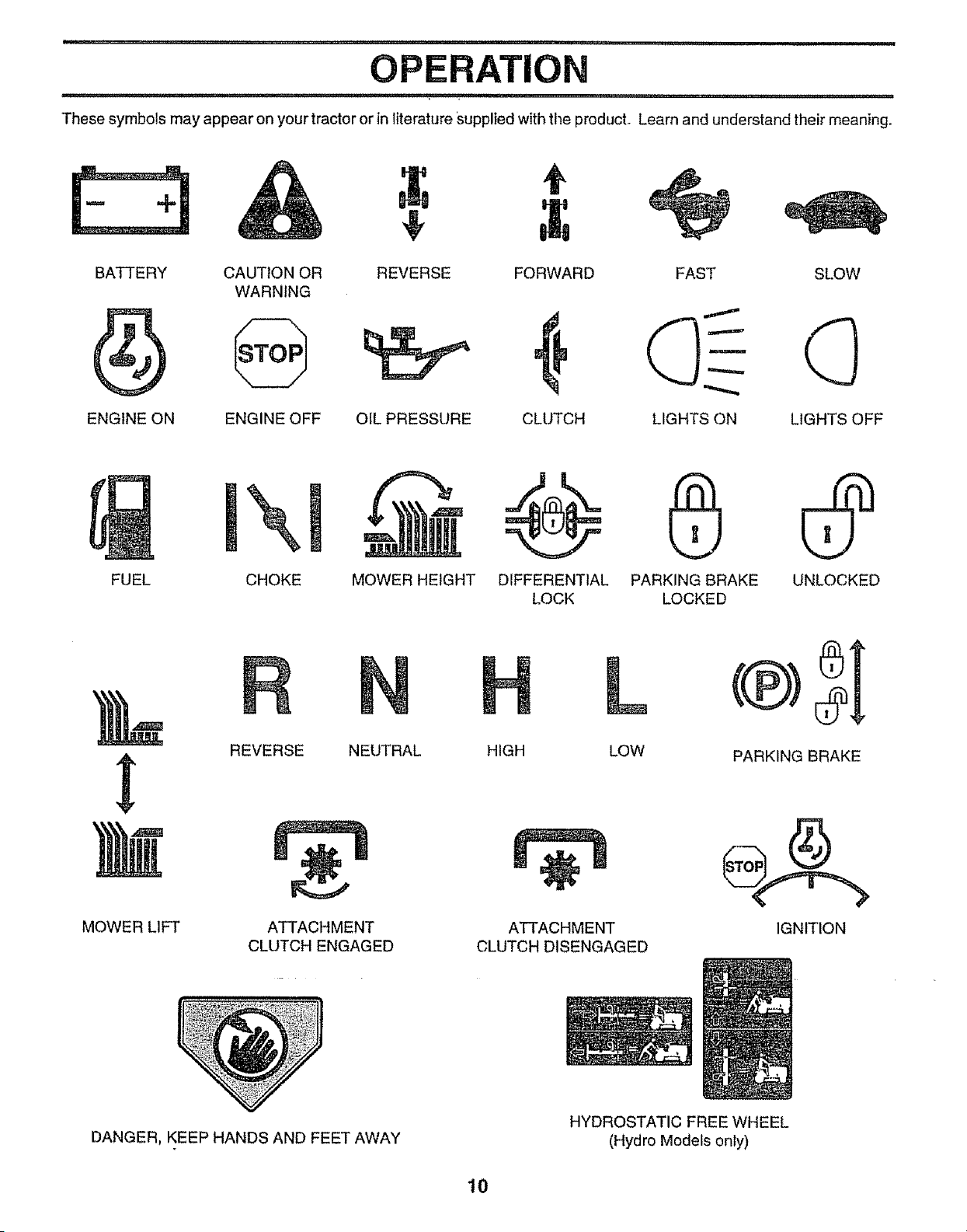
These symbols may appear on your tractor or in literature Supplied with the product. Learn and understand their meaning.
BATTERY CAUTION OR
WARNING
ENGINE ON ENGINE OFF OIL PRESSURE
FORWARD SI.OW
CLUTCH LIGHTS OFF
FAST
LIGHTS ON
FUEL CHOKE MOWER HEIGHT DIFFERENTIAL PARKING BRAKE UNLOCKED
LOCK LOCKED
MOWER LIFT
REVERSE NEUTRAL
ATTACHMENT
CLUTCH ENGAGED
L
HIGH LOW
ATTACHMENT
CLUTCH DISENGAGED
PARKING BRAKE
IGNITION
DANGER, KEEP HANDS AND FEET AWAY
HYDROSTATIC FREE WHEEL
(Hydro Models only)
10
OPERATION
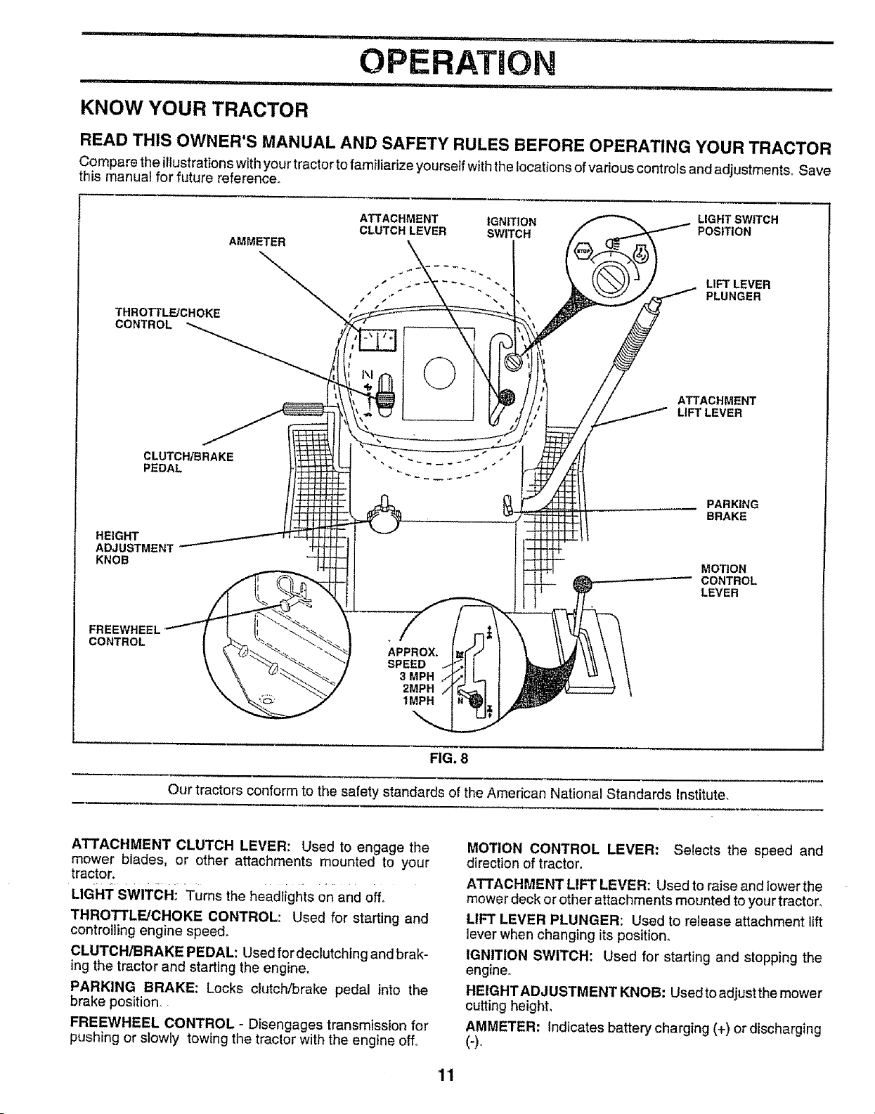
KNOW YOUR TRACTOR
READ THIS OWNER'S MANUAL AND SAFETY RULES BEFORE OPERATING YOUR TRACTOR
Compare iheillustrationswithyour tractor tofamiliadzeyourself withthe locations of various controls and adjustments. Save
this manual for future reference°
THROTTLE/CHOKE
CONTROL
AMMETER
ATTACHMENT IGNITION LIGHT SWITCH
CLUTCH LEVER SWITCH POSITION
. " " 4, LIFT LEVER
., PLUNGER
©
ATTACHMENT
LIFT LEVER
CLUTCH/BRAKE
PEDAL
HEIGHT
ADJUSTMENT
KNOB
PARKING
BRAKE
MOTION
CONTROL
LEVER
FRI
CONTROL
APPROX.
SPEED
3 MPH
2MPH
1MPH
FIG. 8
Our tractors conform to the safety standards of the American National Standards Institute.
ATTACHMENT CLUTCH LEVER: Used to engage the
mower blades, or other attachments mounted to your
tractor.
LIGHT SWITCH: Turns the headlights on and off,
THROTTLE/CHOKE CONTROL: Used for starting and
controlling engine speed,
CLUTCH/BRAKE PEDAL: Used for declutching and brak-
ing the tractor and starting the engine.
PARKING BRAKE: Locks clutch/brake pedal into the
brake position,
FREEWHEEL CONTROL - Disengages transmission for
pushing or slowly towing the tractor with the engine off°
MOTION CONTROL LEVER: Selects the speed and
direction of tractor.
ATTACHMENT LIFT LEVER: Used to raise and tower the
mower deck or other attachments mounted to your tractor,
LIFT LEVER PLUNGER: Used to release attachment lift
lever when changing its position,
IGNITION SWITCH: Used for starting and stopping the
engine.
HEIGHTADJUSTMENT KNOB: Used to adjust the mower
cutting height,
AMMETER: Indicates battery charging (+) or discharging
'1'1
OPERATION
i , i , i , i i1,, ,1 n, ,,,i =1, i iii . _,,_,, .........
The operation of any tractor can result in foreign objects thrown into the eyes, which can
result in severe eye damage. Always wear safety glasses or eye shields while operating your
tractor or performing any adjustments or repairs. We recommend a wide vision safety mask
over the spectacles or standard safety glasses.
,H, L,_±, ,_ I,L.,,,_, L.. ,.i ,,,11, i,,,,,,,11,,,,i,,, ,, i ,M,II, I,, i,
HOW TO USE YOUR TRACTOR
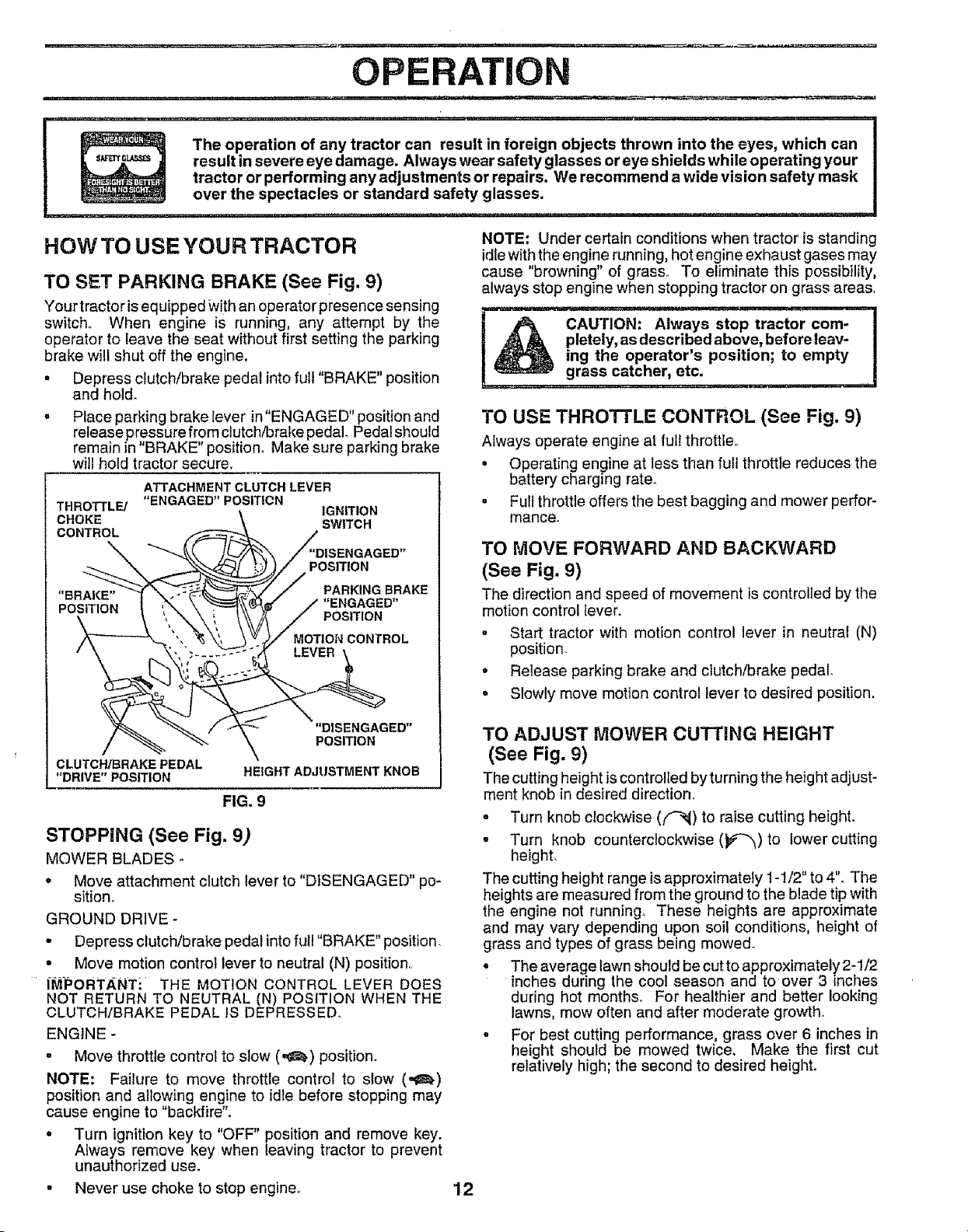
TO SET PARKING BRAKE (See Fig. 9)
Your tractor isequipped With an operator presence sensing
switch,, When engine is running, any attempt by the
operator to leave the seat without first setting the parking
brake will shut off the engine,
. Depress clutch/brake pedal into full "BRAKE" position
and holdo
° Place parking brake lever in"ENGAGED" position and
release pressure from clutch/brake pedal. Pedal should
remain in "BRAKE" position. Make sure parking brake
will hold tractor secure,
ATTACHMENT CLUTCH LEVER
THROTTLE/ "ENGAGED" POSITION IGNITION
CHOKE SWITCH
CONTROL
GED"
POSITION
"BRAKE" PARKING BRAKE
POSITION "ENGAGED"
POSITION
MOTION CONTROL
CLUTCH/BRAKE PEDAL
"DRIVE" POSITION
"DISENGAGED"
POSITION
HEIGHT ADJUSTMENT KNOB
FIG. 9
STOPPING (See Fig. 9)
MOWER BLADES -
,' Move attachment clutch lever to "DISENGAGED" po-
sition.
GROUND DRIVE -
• Depress clutch/brake pedal into full "BRAKE" position.
• Move motion control lever to neutral (N) position,,
IM'PORTANTi ` THE MOTION CONTROL LEVER DOES
NOT RETURN TO NEUTRAL (N) POSITION WHEN THE
CLUTCH/BRAKE PEDAL IS DEPRESSED.
ENGINE -
• Move throttle control to s_ow (,,=_,) position.
NOTE: Failure to move throttle control to slow (,,_.)
position and allowing engine to idle before stopping may
cause engine to "backfire".
. Turn ignition key to "OFF" position and remove key.
Always remove key when leaving tractor to prevent
unauthorized use.
NOTE: Under certain conditions when tractor is standing
idle with the engine running, hot engine exhaust gases may
cause "browning" of grass° To eliminate this possibility,
always stop engine when stopping tractor on grass areas,
--_---CAUTi0N: Always---stop tractor com--------]
Jk pletely, as described above, before leav- I
ing the operator s position; to empty !
grass catcher, etc.
TO USE THROTTLE CONTROL (See Fig. 9)
Always operate engine at full throttle
• Operating engine at less than full throttle reduces the
battery charging rater
• Full throttle offers the best bagging and mower perfor-
mance.
TO MOVE FORWARD AND BACKWARD
(See Fig. 9)
The direction and speed of movement is controlled by the
motion control lever,
o Start tractor with motion control lever in neutral (N)
position.
* Release parking brake and clutch/brake pedal.
o Slowly move motion control lever to desired position.
TO ADJUST MOWER CU'I-riNG HEIGHT
(See Fig. 9)
The cutting height is controlled byturning the height adjust-
ment knob in desired direction,
= Turn knob clockwise (('-_) to raise cutting height.
. Turn knob counterclockwise (_)to lower cutting
heighL
The cutting height range is approximately 1-1/2" to 4"° The
heights are measured from the ground to the blade tip with
the engine not running. These heights are approximate
and may vary depending upon soil conditions, height of
grass and types of grass being mowed.
• The average lawn should be cut to approximately 2-1/2
inches during the cool season and to over 3 inches
during hot months,r For healthier and better looking
lawns, mow often and after moderate growth_
° For best cutting performance, grass over 6 inches in
height should be mowed twice. Make the first cut
relatively high; the second to desired height.
• Never use choke to stop engine.
12
OPERATmON
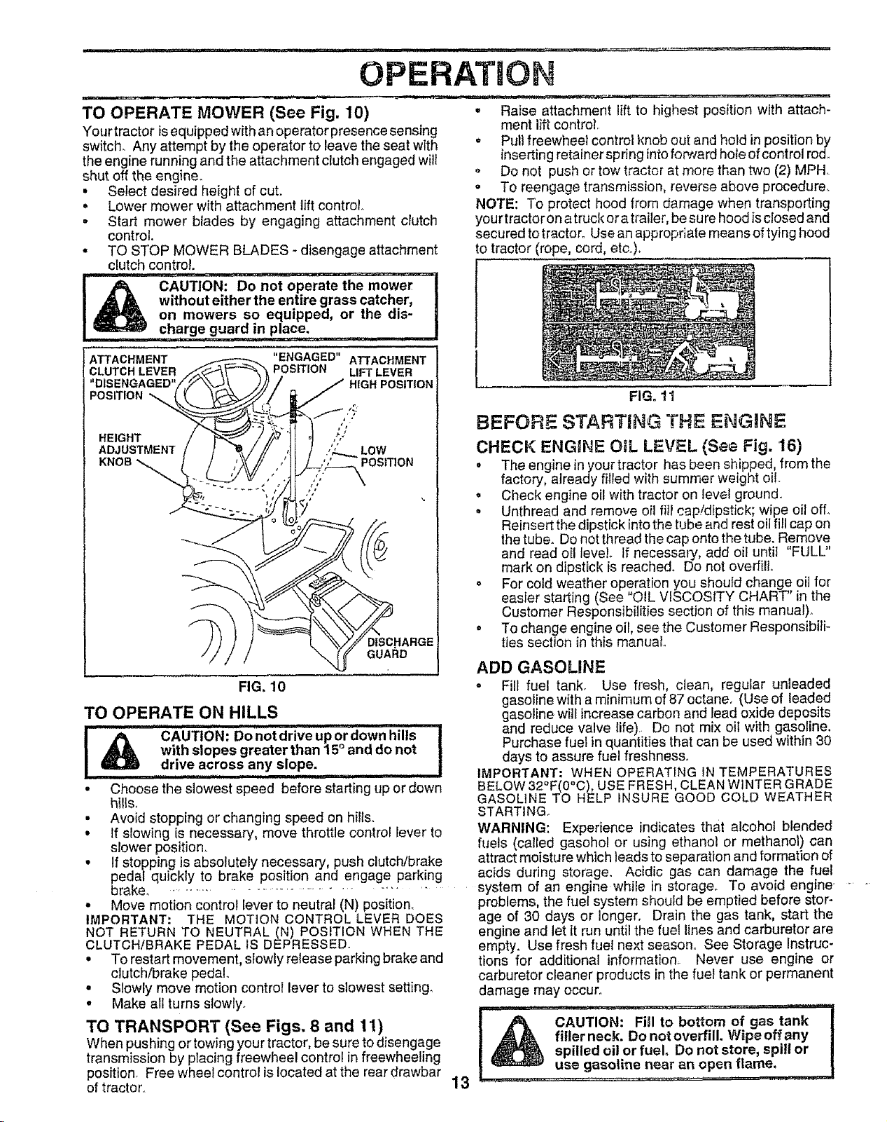
TO OPERATE MOWER (See Fig. 10)
Your tractor isequipped with an operator presence sensing
switch. Any attempt by the operator to leave the seat with
the engine running and the attachment clutch engaged will
shut off the engine.
• Select desired height of cut.
, Lower mower with attachment lift control
• Start mower blades by engaging attachment clutch
control.
• TO STOP MOWER BLADES- disengage attachment
clutch control.
CAUTION: Do not operate the mower
without either the entire grass catcher,
on mowers so equipped, or the dio-
..............charge guard in, place: ..............
" G ED"
i ATTACHMENT _ EN AG ATTACHMENT
=CLUTCH LEVER _.._:_,_-'_ POSITION LIFT LEVER
DISENGAGED"i_7/_Xx_\ ).)) / ./I HIGH POSITION
.E,G.T °1
AO UST ENTt 1 J # ,it / ,'Z.._.LOW
HARGE
GUAI_D
FIG. 10
TO OPERATE ON HILLS
= ran,,=, = I '1
I _ CAUTION: Do notdrive uP ordown hills !
with slopes greater than 15 ° and do not
drive across any slope.
.......... i I I1' I I1'11111111 ii
° Choose the slowest speed before starting up ordown
hills,
• Avoid stopping or changing speed on hills.
° If slowing is necessary, move throttle control lever to
slower position_
° If stopping is absolutely necessary, push clutch/brake
pedal quickly to brake position and engage parking
brake. . ......................................
• Move motion control lever to neutral (N) position.
IMPORTANT: THE MOTION CONTROL LEVER DOES
NOT RETURN TO NEUTRAL (N) POSITION WHEN THE
CLUTCH/BRAKE PEDAL IS DEPRESSED_
° To restart movement, slowly release parking brakeand
clutch/brake pedal..
= Slowly move motion control lever to slowest setting.
• Make all turns slowly.
TO TRANSPORT (See Figs, 8 and 11)
When pushing or towing your tractor, be sure to disengage
transmission by placing freewheel control in freewheeling
position. Free wheel control is located at the rear drawbar
of tractor.
• Raise attachment lift to highest position with attach-
ment lift control.
° Pull freewheel control knob out and hold in position by
inserting retainer spring into forward hole of control rod.
o Do not push or tow tractor at more than two (2) MPHo
o To reengage transmission, reverse above procedure.
NOTE: To protect hood from damage when transporting
yourtractoron a truck ora trailer, be sure hood is closed and
secured to tractor° Use an appropriate means of tying hood
to tractor (rope, cord, etc.),
13
FIG. 11
BEFORE STARTING THE ENGINE
CHECK ENGINE OIL LEVEL (See Fig. 16)
• The engine in your tractor has been shipped, from the
factory, already filled with summer weight oil
, Check engine oil with tractor on level ground.
. Unthread and remove oil fill cap!dipstick; wipe oil off.
Reinsert the dipstick into the tube and rest oil fill cap on
the tube. Do not thread the cap onto the tube. Remove
and read oil level If necessary, add oil until "FULL"
mark on dipstick is reached. Do not overfill.
o For cold weather operation you should change oil for
easier starting (See "OIL VISCOSITY CHART" in the
Customer Responsibilities section of this manual).
• To change engine oil, seethe Customer Responsibili-
ties section in this manual.
ADD GASOLINE
o Fill fuel tank_ Use fresh, clean, regular unleaded
gasoline with a minimum of 87 octane. (Use of leaded
gasoline will increase carbon and lead oxide deposits
and reduce valve life) Do not mix oil with gasoline.
Purchase fuel in quantities that can be used within 30
days to assure fue! freshness.1
IMPORTANT: WHEN OPERATING IN TEMPERATURES
BELOW 32°F(0°C), USE FRESH, CLEAN WINTER GRADE
GASOLINE TO HELP INSURE GOOD COLD WEATHER
STARTING.
WARNING: Experience indicates that alcohol blended
fuels (called gasohol or using ethanol or methanol) can
attract moisture which leads to separation and formation of
acids during storage. Acidic gas can damage the fuel
system of an engine while in storage. To avoid engine
problems, the fuel system should be emptied before stor-
age of 30 days or longer, Drain the gas tank, start the
engine and let it run until the fuel lines and carburetor are
empty. Use fresh fuel next season. See Storage Instruc-
tions for additional information, Never use engine or
carburetor cleaner products in the fuel tank or permanent
damage may occur.
I ,_:: CAUTION: Fi_
_, fitlerneck. Do not overfilL Wipeoffany |
spilled oil or fuel Do not store, spitl or
use gasoline near an open flame.
..... near an open flame. ,,J
OPERATION
TO START ENGINE (See Fig, 9)
When starting the engine for the first time or if the engine
has run out of fuel, it will take extra cranking time to move
fuel from the tank to the engine,
, Be sure freewheel Control is in the transmission en-
gaged position,
° Sit on seat in operating position, depress clutch/brake
pedal and set parking brake.
, Place motion control lever in neutral (N) position.
o Move attachment clutch to "DISENGAGED" position..
= Move throttle control to choke (N) position.
Note: Before starting, read the warm and cold starting
procedures below.
° Insert key into ignition and tum keyclockwise to"START"
position and release key as soon as engine starts. Do
not run starter continuously for more than fifteen sec-
onds per minute. If the engine does not start after
several attempts, move throttle control to fast (,_)
position, wait a few minutes and try again. If enginestilt
does not start, move the throttle control back to the
choke (N) position and retry°
WARM WEATHER STARTING (50 ° F and above)
° When engine starts, move the throttle control to the fast
(,_) position.1
• The attachments and ground drivecan nowbe used. If
the engine does not accept the load, restart the engine
and allow it to warm up for one minute using the choke
as described above°
COLD WEATHER STARTING ( 50 ° F and below)
- When engine starts, allow engine to run with the throttle
control in the choke (N) position until the engine runs
roughly, then move throttle control to fast (,¢_) position.
This may require an engine warm-up period from
several seconds to several minutes, depending on the
temperature.
HYDROSTATIC TRANSMISSION WARM UP
= Before driving the unit in cold weather, the transmis*
sion should be warmed up as follows:
• Be sure the tractor is on level ground.
• Place the motion control lever in neutral
Release the parking brake and let the clutch/brake
slowly return to operating position.
• Allow one minute for transmission to warm up.
This can be done during the engine warm up
period.
= The attachments can also be used during the engine
warm-up period afterthe transmission has been warmed
up ....
NOTE: If at a high altitude (above 3000 feet) or in cold
temperatures (below 32 F) the carburetor fuel mixture may
need to be adjusted for best engine performance. See "TO
ADJUST CARBURETOR" in the Service and Adjustments
section of this manual.
PURGE TRANSMISSION
CAUTION'_"Never engage Or disengag_q
freewheel lever while the engine is run- |
ning. /
To ensure proper operation and performance, it is recom-
mended that the transmission be purged before operating
tractor for the first time° This procedure wil} remove any
trapped air inside the transmission which may have devel-
oped during shipping of your tractor_
IMPORTANT, SHOULD YOUR TRANSMISSION REQUIRE
REMOVAL FOR SERVICE OR REPLACEMENT, iT
SHOULD BE PURGED AFTER REINSTALLAT!ON
BEFORE OPERATING THE TRACTOR°
° Place tractor safely on level surface with engine off and
parking brake seL
• Disengage transmission by placing freewheel control
in freewheeling position (See "TO TRANSPORT" in
this section of manual).
. Sittinginthetractorseat, startengine. Aftertheengine
is running, move throttle control to slow (,_) position°
With motion control lever in neutral (N) position, slowly
disengage clutch/brake pedal.
. Move motion control lever to full forward position and
hold for five (5) seconds. Move lever to full reverse
position and hold for five (5) seconds. Repeat this
procedure three (3) times.
NOTE: During this procedure there will be no movement of
drive wheels. The air is being removed from hydraulic drive
system.
° Move motion control lever to neutral (N) position° Shut-
off engine and setparking brake.
° Engage transmission by placing freewheel control in
driving position (See "TO TRANSPORT" in this section
of manual).
o Sittinginthetractor seat, start engine, Afterthe engine
is running move throttle control to half (1/2) speed°
With motion control lever in neutral (N) posit on, s ow y
disengage clutch/brake pedal.
° Slowly move motion control lever forward, after the
tractor moves approximately five (5) feet, slowly move
motion control lever to reverse position. After the
tractor moves approximately five (5) feet return the
motion control lever to the neutral (N) position. Repeat
this procedure with the motion control lever three (3)
times.
° Your tractor is now purged and now ready for normal
operati6n,
14

CUSTO
BILmES
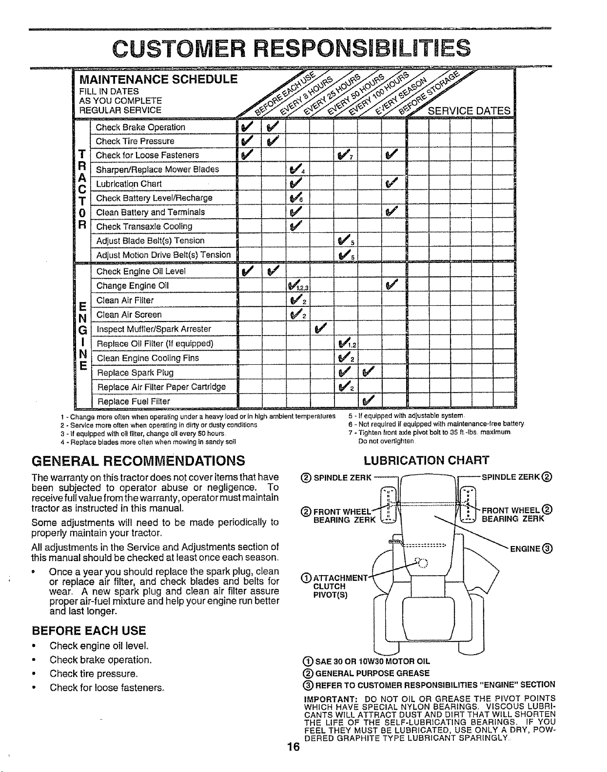
MAINTENANCE SCHEDULE
FILLIN DATES
AS YOU COMPLETE
REGULAR SERVICE SERVICE DATES
CheckBrake Operation _
Check Tire Pressure I_ I_
T CheckforLooseFasteners _ @_'7
R Sharpen/Repiace Mower Blade's.......... _4
A
C EUloricaiionchart .................... t_ _ __
T Chec. k Battery LevettRecharge ..............
0 Clean Battery and Terminals 6/' .......... _" [
a CheckTransaxle Cooling ...............
Adjust Blade Belt(s)Tension _#'s
Adjust Motion Drive Belt(s) Tension
Check Engine Oil Level _
Change EngineOiE .... _2,a ...... _ _ ._
E Clean Air Filter ............. 6/2 , ._
N Clean Air Screen 6_4'2
G Inspect MuffiedSparkArrester , if ..................
I Replace Oil Filter (if equipped) _,2
N Ctean EngineCooling Fins ......... 1_2
Replace Spark Plug ................ 6/ ,,,,_ [ __
ReplaceAir Filter Paper Cartridge 6##2
Replace Fuel Filter I_
1 - Change more o|ten when operating under a heavy load or in high ambient temperatures
2 - Sewice more often when operating in dirty or dusty conditions
3 _ if equipped with oil filter, change oil every 50 hours
4 _ Replace blades mere often when mowing in sandy soil
5 - If equipped with adjustable system,
6 - Not required t! equipped with maintenance4ree battery
7 - Tighten front axle pivot belt to 35 ft *ibs, maximum
Do not overttghten
GENERAL RECOMMENDATIONS
The warranty on this tractor does not cover items that have
been subjected to operator abuse or negligence. To
receive full value from the warranty, operator must maintain
tractor as instructed in this manual.
Some adjustments will need to be made periodically to
properly maintain your tractor.
All adjustments in the Service and Adjustments section of
this manual should be checked at least once each season°
• Once a year you should replace the spark plug, clean
or replace air filter, and check blades and belts for
wear. A new spark plug and clean air filter assure
proper air-fuel mixture and help your engine run better
and last longer.
LUBRICATION CHART
(_ SPINDLE 2
@
BEARING ZERK
O
CLUTCH
PIVOT(S)
®
"FRONT WHEEL®
BEARING ZERK
ENGINE®
BEFORE EACH USE
• Check engine oil level.
• Check brake operation.
• Checktire pressure.
• Check forloose fasteners°
(_ SAE30 OR10W30MOTOROIL
® GENERALPURPOSEGREASE
(_) REFERTO CUSTOMERRESPONSIBILITIES"ENGINE"SECTION
IMPORTANT: DO NOT OIL OR GREASE THE PIVOT POINTS
WHICH HAVESPECIALNYLON BEARINGS. VISCOUS LUBRI-
CANTS WiLLATTRACT DUST AND DIRT THAT WILL SHORTEN
THE LIFE OF THE SELF-LUBRICATING BEARINGS, IF YOU
FEELTHEY MUST BE LUBRICATED,USE ONLY A DRY, POW-
DERED GRAPHITETYPE LUBRICANTSPARINGLY
16
.._ .ITI.I i.ii .................... i ............................. i
CUSTOMER RESPONSiBiLITiES
TRACTOR
Always observe safety rules when performing any mainte-
r_ance°
BRAKE OPERATION
If tractor requires more than six (6) feet stopping distance
at high speed in highest gear, then brake must be adjusted.
(See "TO ADJUST BRAKE" in the Service and Adjust-
ments section of this manual).
TIRES
• Maintain proper air pressure in all tires (See "PROD-
UCT SPECIFICATIONS on page 3 of this manual).
• Keep tires free of gasoline, oil, or insect control chemi-
cals which can harm rubber.
• Avoid stumps, stones, deep ruts, sharp objects and
ether hazards that may cause tire damage°
NOTE; To seal tire punctures and prevent fiat tires due to
siow leaks, tire sealant may be purchased from your local
parts dealero Tire sea_ant also prevents tire dry rot and
corrosion.
BLADE CARE
For best results mower blades must be kept sharp. Re-
place bent or damaged blades..
BLADE REMOVAL (See Fig. 13)
- Raise mower to highest position to allow access to
blades.
. Remove hex bo_t,lockwasher and flat washer securing
blade.
° install new or resharpened blade with trailing edge up
towards deck as shown.
. Reassemble hex bolt, lock washer and flat washer in
exact order as shown.
= Tighten bolt securely (30-35 Ft. Lbs. torque).
IMPORTANT: BLADE BOLT 1SGRADE 8 HEATTREATED.
NOTE: We do not recommend sharpening blade- but if you
do, be sure the b_ade is batanced_
BLADE MANDREL
FIG. 13
iii1..i.,.., i1.111111.111ii
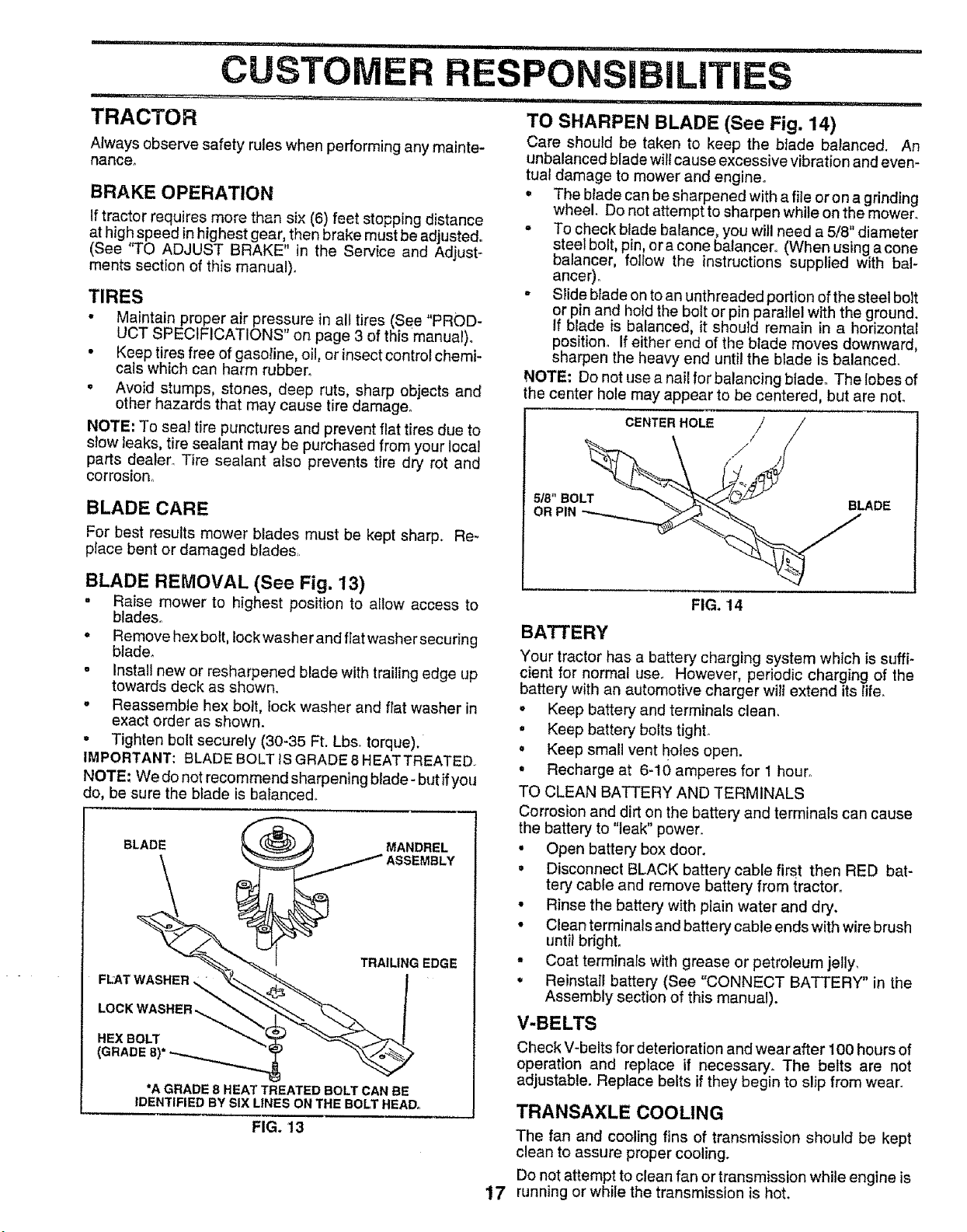
TO SHARPEN BLADE (See Fig. 14)
Care should be taken to keep the blade balanced. An
unbalanced blade will cause excessive vibration and even-
tual damage to mower and engine_
• The blade can be sharpened with a file or on a grinding
wheel. Do not attempt to sharpen while on the mower.
° To check blade balance, you will need a 5/8" diameter
steel bolt, pin, or a cone balancero (When using a cone
balancer, follow the instructions supplied with bal-
ancer) o
- Slide btade on to an unthreaded portion of the steel bolt
or pin and hold the bolt or pin paraIlel with the ground.
if blade is balanced, it shouId remain in a horizontal
position, if either end of the blade moves downward,
sharpen the heavy end until the blade is balanced.
NOTE: Do not use a nail for balancing blade. The lobes of
the center hole may appear to be centered, but are not.
CE. ER.OL / /
FIG. 14
BATTERY
Your tractor has a battery charging system which is suffi-
cient for normal use. However, periodic charging of the
battery with an automotive charger wilt extend its life.
o Keep battery and terminals clean.
. Keep battery bolts tight.
• Keep small vent holes open.
. Recharge at 6-'10 amperes for I hour°
TO CLEAN BATTERY AND TERMINALS
Corrosion and dirt on the battery and terminals can cause
the battery to "leak" power.
• Open battery box door.
° Disconnect BLACK battery cable first then RED bat-
tery cable and remove battery from tractor.
• Rinse the battery with plain water and dry.
• Clean terminals and battery cable ends with wire brush
until bright.
Coat terminals with grease or petroleum jelly.
• Reinstall battery (See "CONNECT BATTERY" in the
Assembly section of this manual).
V-BELTS
Check V-belts for deterioration and wear after 100 hours of
operation and replace if necessary. The belts are not
adjustable. Replace belts if they begin to slip from wear.
17
TRANSAXLE COOLING
The fan and cooling fins of transmission should be kept
clean to assure proper cooling.
Do not attempt to clean fan or transmission while engine is
running or while the transmission is hot.
CUSTOMER
Inspect cooling fan to be sure fan blades are intact and
clean.
Inspect cooling fins for dirt, grass clippings and other
materials. To prevent damage to seals, do not use
compressed air or high pressure sprayer to clean
cooling fins_
TRANSAXLE PUMP FLUID
The transaxle was sealed at the factory and fluid mainte-
nance is not required for the life of the transaxle. Should the
transaxle ever leak or require servicing, cantact your near-
est authorized service center/department.
ENGINE
LUBRICATION
Only use high quality detergent oil rated with API service
classification SF, SG or SH_ Select the oil's SAE viscosity
grade according to your expected operating temperature_
[ SAEV!SCOS!_GRADES
:;.;°:2°..0.o ,;:,0,'0.00 ,0;o.,%:
I TEMPERATURE RANGE ANTICIPATED BEFORE NEXT OiL CHANGE
FIG. 15
NOTE: Although multi-viscosity oils (5W30, 10W30 etc,.)
improve starting in cold weather, these multi-viscosity oils
Will result in increased oil consumption when used above
32°F, Check your engine oil level more frequently to avoid
possible engine damage from running tow on oil.
Change the oil after every 50 hours of operation or at least
once a year if the tractor is not used forS0 hours in one year.
Check the crankcase oil level before starting the engine
and after each eight (8) hours of operation° Tighten oil fill
cap/dipstick securely each time you check the oil level.
TO CHANGE ENGINE OIL (See Fig. 15 and 16)
Determine temperature range expected before oil change.
All oil must meet API service classification SF, SG or SH.
• Be sure tractor is on level surface,
• Oil will drain more freely when warm.
° Catch oil in a suitable container..
• Remove oil fill cap/dipstick. Be careful not to allow dirt
to enter the engine when changing oil.
• Remove drai n piug_
° After oil has drained completeiy_ repiace'oii drain plug
and tighten securely.
• Refill engine with oil through oil fill dipstick tube. Pour
slowly, Do not overfill. For approximate capacity see
"PRODUCT SPECIFICAT!ONS" on page 3 of this
manual.
° Use gauge on oil fill cap/dipstick for checking level
Insert dipstick into the tube and rest the oil fill cap on the
tube. Do not thread the cap onto the tube when taking
reading_ Keep oil at"FULL" line on dipstick. Tighten
cap onto the tube securely when finished.
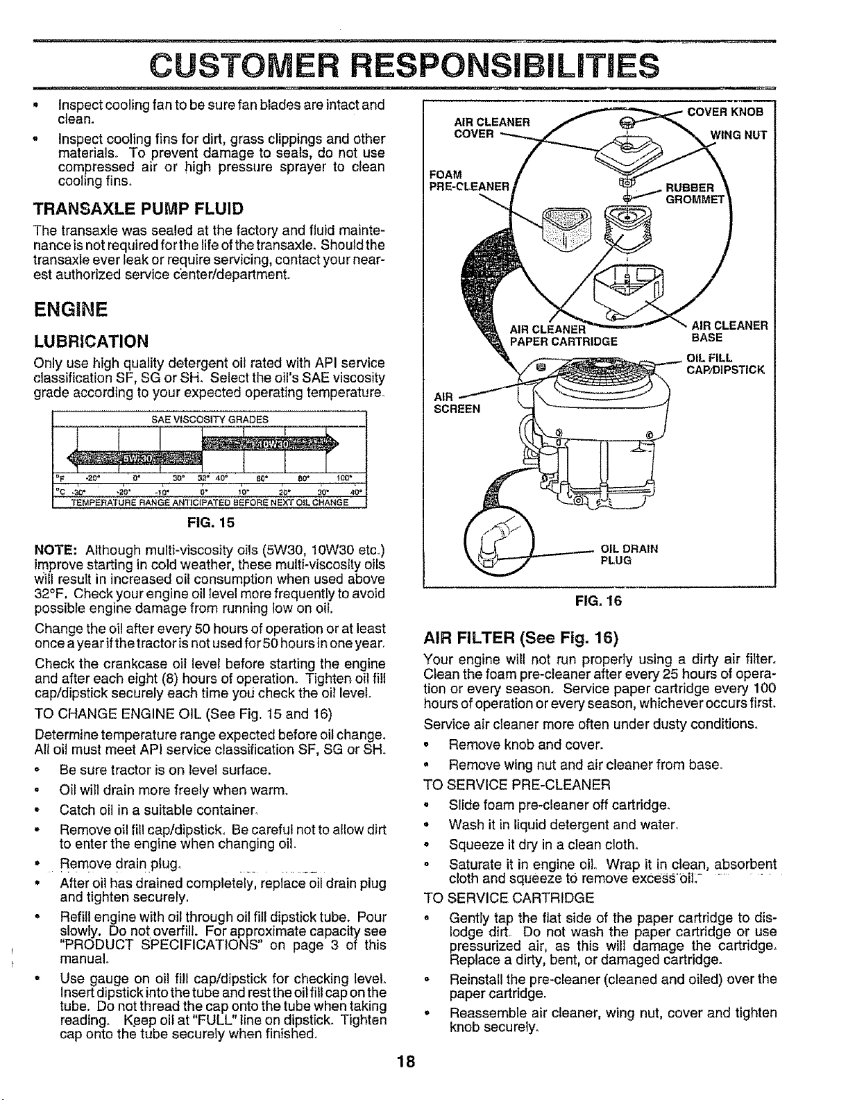
AIR CLEANER
COVER WING NUT
FOAM
PRE-CLEANER
PAPER CARTRIDGE
AIR
SCREEN
OIL DRAIN
PLUG
AIR CLEANER
BASE
OiL FILL
CAP/DIPSTICK
FIG. 16
AIR FILTER (See Fig. 16)
Your engine will not run properly using a dirty air filter.
Ctean the foam pre-cteaner after every 25 hours of opera-
tion or every season. Service paper cartridge every 100
hours of operation or every season, whichever occurs first.
Service air cleaner more often under dusty conditions.
• Remove knob andcover.
• Remove wing nut and air cleaner from base.
TO SERVICE PRE-CLEANER
. Slide foam pre*cleaneroff cartddgeo
• Wash it in liquid detergent and water,
= Squeeze it dry in a clean cloth.
o Saturate it in engine oil Wrap it in clean, absorbent
cloth and squeeze to remove excess'OiL ........
TO SERVICE CARTRIDGE
o Gently tap the flat side of the paper cartridge to dis-
lodge dirt,. Do not wash the paper cartridge or use
pressurized air, as this will damage the cartddgeo
Replace a dirty, bent, or damaged cartridge.
° Reinstall the pre-cleaner (cleaned and oiled) over the
paper cartridge.
• Reassemble air cleaner, wing nut, cover and tighten
knob securely_
18
,,,,,,, _,,,L,,,,,,, .... ................. ................. I i i1=1==111'1, II="I'N'=IN' , ..... i=1
CUSTOMER RESPONSIBILITIES
CLEAN AIR SCREEN (See Fig. 16)
Air screen must be kept free of dirt and chaff to prevent
engine damage from overheating_ Clean with awire brush
or compressed air to remove dirt and stubborn dried gum
fibers.
CLEAN AIR iNTAKE/COOLING AREAS
To insure proper cooling, make sure the grass screen,
cooling fins, and other external surfaces of the engine are
kept clean at all times.
Every 100 hours of operation (more often under extremely
dusty, dirty conditions), remove the blower housing and
other cooling shrouds. Clean the cooling fins and external
surfaces as necessaryr Make sure the cooling shrouds are
reinstalled.
NOTE: Operating the engine with a blocked grass screen,
dirty or plugged cooling fins, and/or coo_ing shrouds re-
moved will cause engine damage due to overheating.
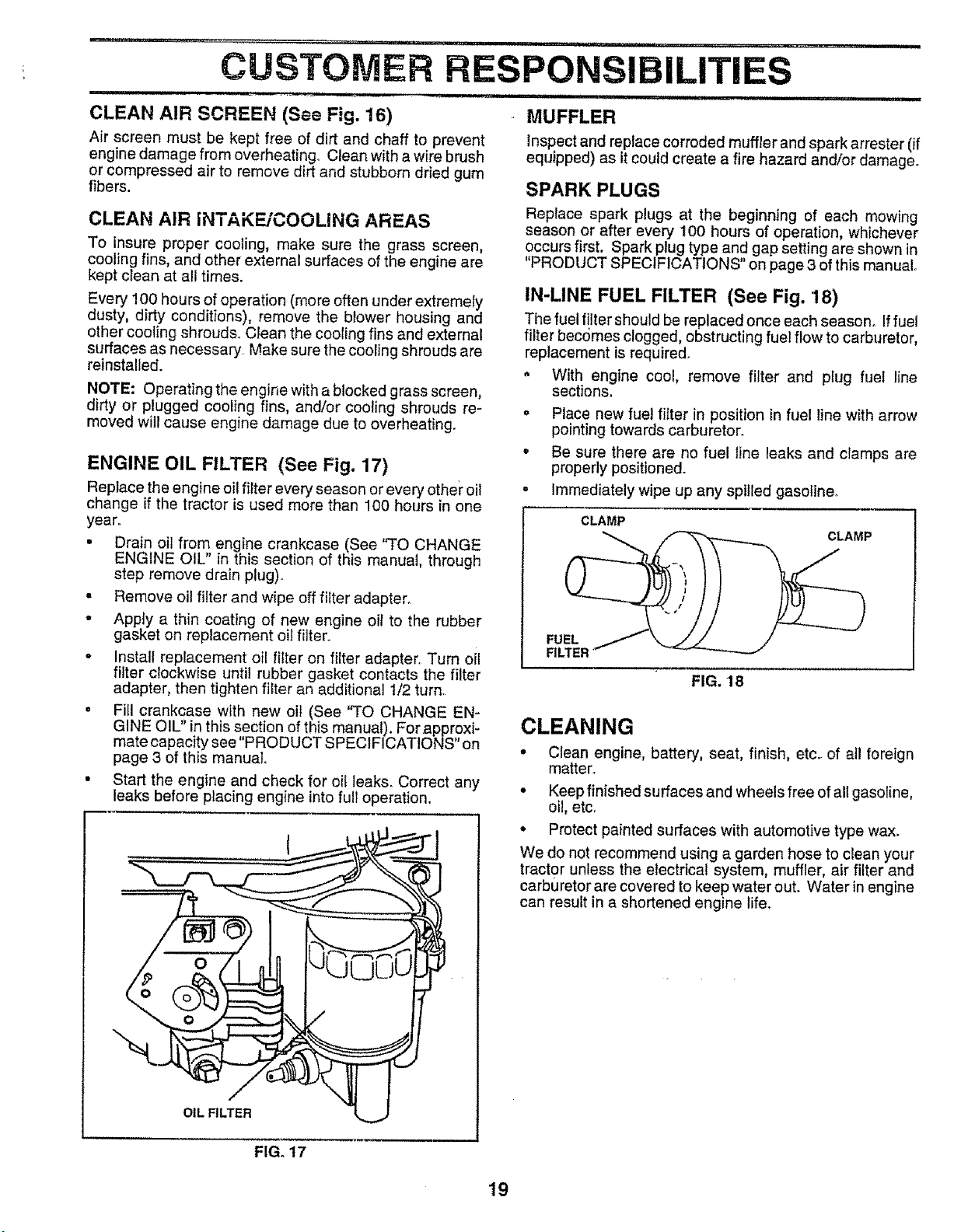
ENGINE OIL FILTER (See Fig. 17)
Replace the engine oil filter every season or every other" oil
change if the tractor is used more than 100 hours in one
year.
• Drain oil from engine crankcase (See "TO CHANGE
ENGINE OIL" in this section of this manual, through
step remove drain plug).
= Remove oil filter and wipe off filter adapter.
• Appfy a thin coating of new engine oil to the rubber
gasket on replacement oil filter.
• Install replacement oil filter on filter adapter. Turn oil
filter clockwise until rubber gasket contacts the filter
adapter, then tighten filter an additional 1/2 turn.
• Fill crankcase with new oil (See "TO CHANGE EN-
GINE OIL" in this section of this manual), Forapproxi-
mate capacity see "PRODUCT SPECIFICATIONS" on
page 3 of this manual.
• Start the engine and check for oil leaks. Correct any
leaks before placing engine into full operation.
OIL FILTER
MUFFLER
Inspect and replace corroded muffler and spark arrester (if
equipped) as it could create a fire hazard and/or damage.
SPARK PLUGS
Replace spark plugs at the beginning of each mowing
season or after every I O0 hours of operation, whichever
occurs first. Spark plug type and gap setting are shown in
"PRODUCT SPECIFICATIONS" on page 3 of this manual°
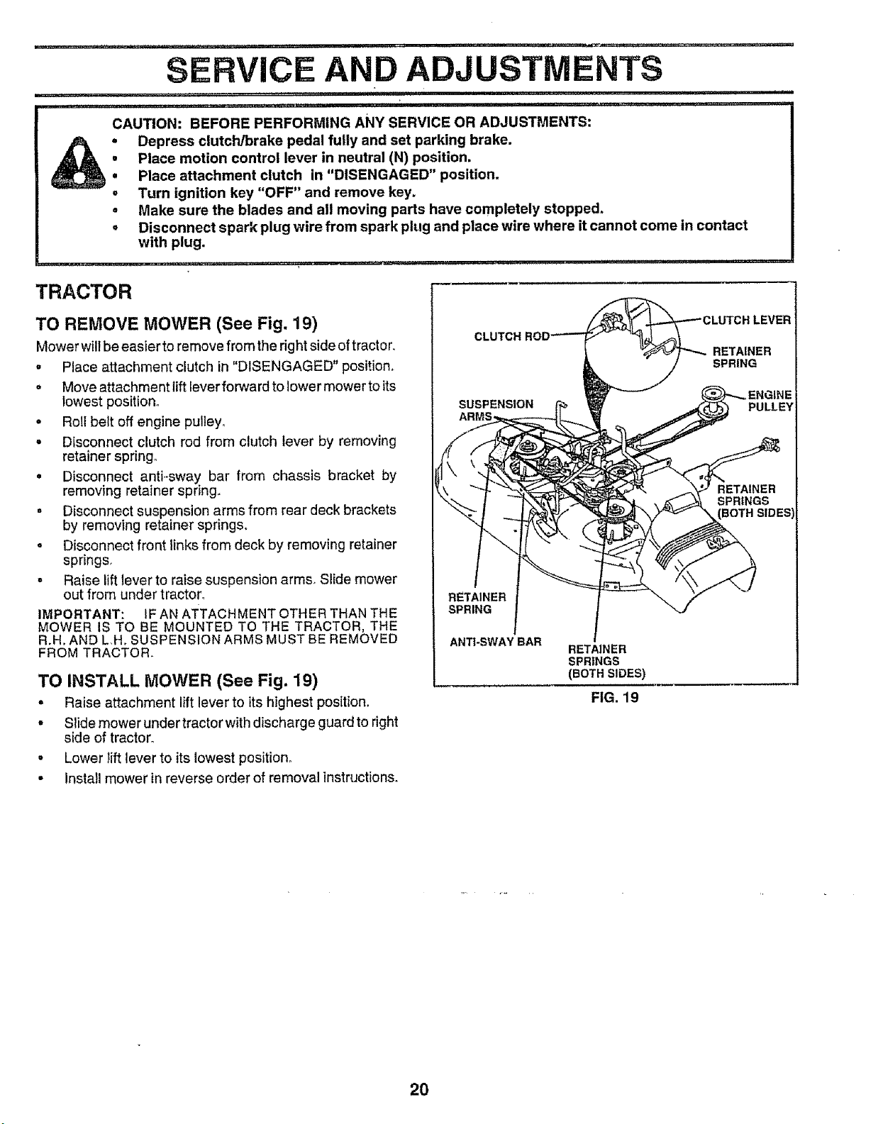
IN-LINE FUEL FILTER (See Fig. '18)
The fuel filter should be replaced once each season. If fuel
filter becomes clogged, obstructing fuel flow to carburetor,
replacement is required.
. With engine cool, remove filter and plug fuel line
sections.
, Place new _uel filter in position in fue_ line with arrow
pointing towards carburetor.
• Be sure there are no fuel line leaks and clamps are
properly positioned.
, Immediately wipe up any spilled gasoline.
CLAMP
CLAMP
FUEL
FILTER
FIG. 18
CLEANING
• Clean engine, battery, seat, finish, etc. of atl foreign
matter_
• Keep finished surfaces and wheels free of all gasoline,
oil, etc.
• Protect painted surfaces with automotive type wax.
We do not recommend using a garden hose to clean your
tractor unless the electrical system, muffler, air filter and
carburetor are covered to keep water out. Water in engine
can result in a shortened engine life.
FIG. 17
19
' i ..... i ii ...................... i1,,,,,,,i.....
SERVICE AND ADJUSTMENTS
L ......... ,,, , , ,., i ii...i,r,,i,rl
...................... i i= i ,IH, ,_,%Yii,i_, i l ill,,
CAUTION: BEFORE PERFORMING ANY SERVICE OR ADJUSTMENTS:
i Depress clutch/brake pedal fully and set parking brake.
O
II
O
Place motion control lever in neutral (N) position.
Place attachment clutch in "DISENGAGED" position.
Turn ignition key "OFF" and remove key.
Make sure the blades and all moving parts have completely stopped.
Disconnect spark plug wire from spark plug and place wire where it cannot come in contact
with plug.
= , , li, ,,i,=,,,,,,,,ill!, i , , ilillllP
....... i i,=, N, ,........
TRACTOR
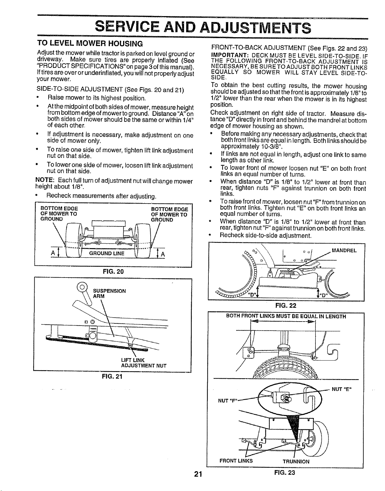
TO REMOVE MOWER (See Fig. 19)
Mower will be easier to remove from the right side of tractor.
• Place attachment clutch in "DISENGAGED" position,
o Move attachment lift lever forward to lower mower to its
lowest position°
. Roll belt off engine pulley°
• Disconnect clutch rod from clutch lever by removing
retainer spring,
• Disconnect anti-sway bar from chassis bracket by
removing retainer spring.,
• Disconnect suspension arms from rear deck brackets
by removing retainer springs.
o Disconnect front links from deck by removing retainer
springs,
• Raise lift lever to raise suspension arms, Slide mower
out from under tractor,
IMPORTANT: IF AN ATTACHMENT OTHER THAN THE
MOWER IS TO BE MOUNTED TO THE TRACTOR, THE
R.H. AND LH, SUSPENSION ARMS MUST BE REMOVED
FROM TRACTOR.
TO INSTALL MOWER (See Fig. 19)
• Raise attachment lift lever to its highest position.
• Slide mower under tractor with discharge guard to right
side of tractor°
• Lower lift lever to its lowest position°
• install mower in reverse order of removal instructions.
RETAINER
SPRING
ANTI-SWAY BAR
RETAINER
SPRINGS
(BOTHSIDES)
FIG. 19
==.==11
20
TO LEVEL MOWER HOUSING
Adjust the mower whlle tractor is parked on level ground or
driveway. Make sure tires are properly inflated (See
"PRODUCT SPECIFICATIONS" on page 3 of this manual).
Iftires are over or underinflated, you wilt not properly adjust
your mower.
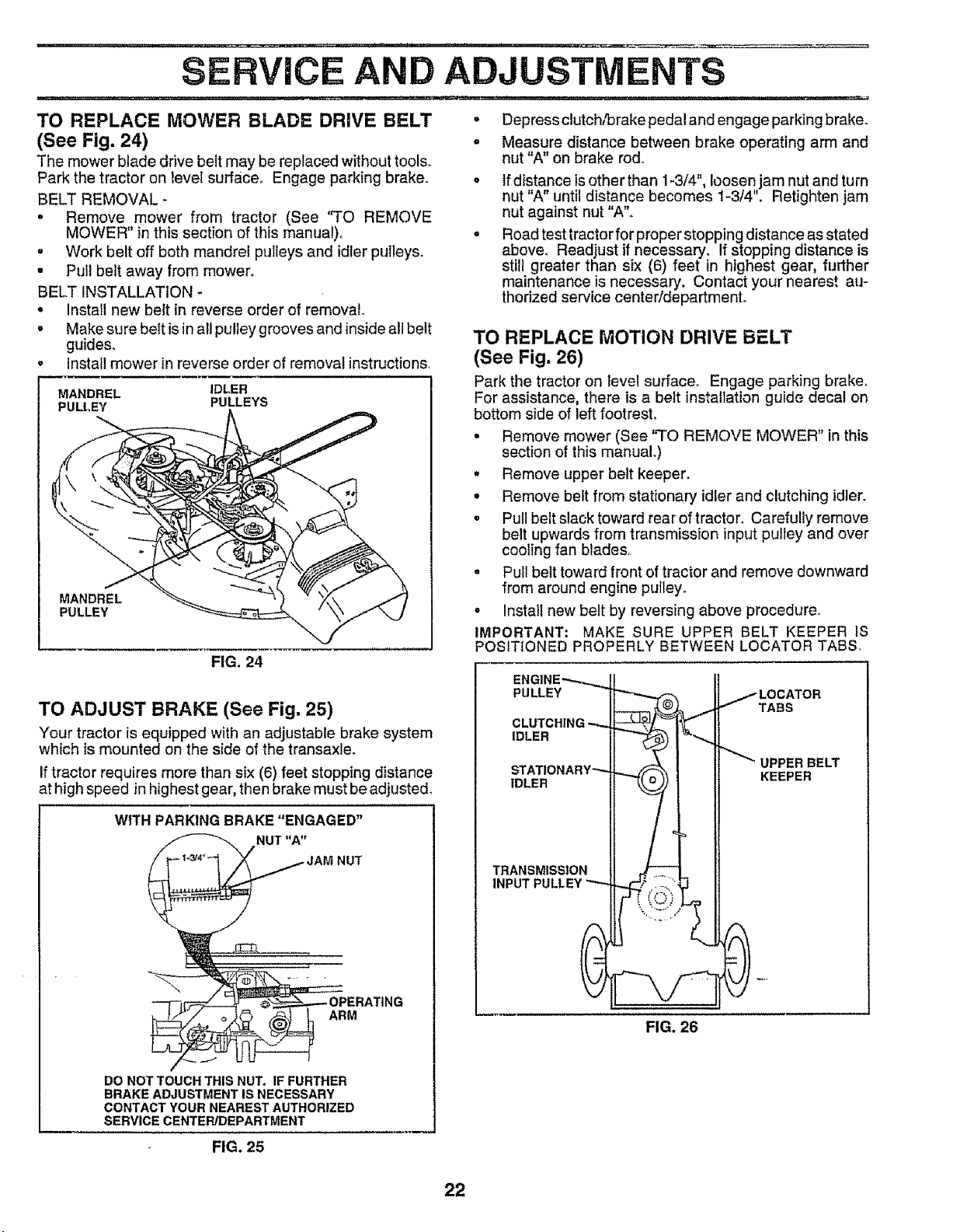
SIDE-TO-SIDE ADJUSTMENT (See Figs° 20 and 21)
- Raise mower to its highest position°
• At the midpoint of both sides of mower, measure height
from bottom edge of mower to ground_ Distance"A" on
both sides of mower should be the same or within 1/4"
of each other.
FRONT-TO-BACK ADJUSTMENT (See Figs. 22 and 23)
IMPORTANT: DECK MUST BE LEVEL SIDE-TO-SIDEo IF
THE FOLLOWING FRONT-TO-BACK ADJUSTMENT IS
NECESSARY, BE SURE TO ADJUST BOTH FRONT LINKS
EQUALLY SO MOWER WILL STAY LEVEL SIDE-TO-
SIDE,
To obtain the best cutting results, the mower housing
should be adjusted so that the front is approximately 1/8" to
1/2" lower than the rear when the mower is in its highest
position.
Check adjustment on right side of tractor° Measure dis-
tance"D" directly infront and behind the mandrel at bottom
edge of mower housing as shown_
• If adjustment is necessary, make adjustment on one
side of mower onlyo
• To raise one side of mower, tighten lift link adjustment
nut on that sider
. To lower one side of mower, loosen lift link adjustment
nut on that side.
NOTE: Each full turn of adjustment nut will change mower
height about 1/8".
. Recheck measurements after adjusting°
BOTTOM EDGE BOTTOM EDGE
OF MOWER TO OF MOWER TO
GROUND GROUND
GROUND LINE
FIG. 20
SUSPENSION
LIFT LINK
ADJUSTMENT NUT
FIG. 21
• Before making any necessary adjustments, checkthat
both front links are equal in length_ Both links should be
approximately 10-3/8".
• If links are not equal in length, adjust one link to same
length as other link,
• To lower front of mower loosen nut "E" on both front
links an equal number of tumso
° When distance "D" is 1/8" to 1/2" Iower at front than
rear, tighten nuts "F" against trunnion on both front
links.
o To raise front of mower, loosen nut"F" from trunnion on
both front links. Tighten nut "E" on both front links an
equal number of turns.
- When distance "D" is 1/8" to 1/2" lower at front than
rear, tighten nut "F" against trunnion on both front links°
• Recheck side-to-side adjustmenL
MANDREL
FIG, 22
BOTH FRONT LINKS MUST BE EQUAL IN LENGTH
NUT "F"
FRONT LINKS TRUNNION
NUT "E"
21 FIG. 23
SERVIC AND ADJUSTMENTS
TO REPLACE MOWER BLADE DRIVE BELT
(See Fig. 24)
The mower blade drive belt may be replaced without tools.
Park the tractor on level surface. Engage parking brake.
BELT REMOVAL -
= Remove mower from tractor (See "TO REMOVE
MOWER" in this section of this manual)°
= Work belt off both mandrel pulleys and idler pulleys.
• Pull belt away from mower.
BELT INSTALLATION -
° Install new belt in reverse order of removal
• Make sure belt is in all pulley grooves and insideall belt
guides.
Install mower in reverse order of removal instructions.
MANDREL IDLER
PULLEY PULLEYS
FIG. 24
MANDREL
PULLEY
TO ADJUST BRAKE (See Fig. 25)
Your tractor is equipped with an adjustable brake system
which is mounted on the side of the transaxle.
If tractor requires more than six (6) feet stopping distance
at high speed in highest gear, then brake must be adjusted,
WITH PARKING BRAKE "ENGAGED"
NUT "A"
NUT
ARM
DO NOTTOUCHTHIS NUT. IF FURTHER
BRAKE ADJUSTMENTIS NECESSARY
CONTACT YOUR NEAREST AUTHORIZED
SERVICE CENTEPJDEPARTMENT
. Depress clutch,_rake pedal and engage parking brake.
° Measure distance between brake operating arm and
nut "A" on brake rod.
° If distance is other than 1-3/4", loosen jam nut and turn
nut "A" until distance becomes 1-3/4". Retighten jam
nut against nut "A".
° Road test tractor for properstopping distance as stated
above. Readjust if necessary. If stopping distance is
still greater than six (6) feet in highest gear, further
maintenance is necessary. Contact your nearest au-
thorized service centeddepartment.
TO REPLACE MOTION DRIVE BELT
(See Fig. 26)
Park the tractor on level surface° Engage parking brake,
For assistance, there is a belt installation guide decal on
bottom side of left footrest,
° Remove mower (See "TO REMOVE MOWER" in this
section of this manual.)
. Remove upper belt keeper.
° Remove belt from stationary idler and clutching idler.
• Pull belt slack toward rear of tractor. Carefully remove
belt upwards from transmission input pulley and over
cooling fan blades
. Pull belt toward front of tractor and remove downward
from around engine pulley.
o Install new belt by reversing above procedure.
IMPORTANT: MAKE SURE UPPER BELT KEEPER IS
POSITIONED PROPERLY BETWEEN LOCATOR TABS.
ENGINE",,.-._._ Il
PULLEY _-_ / LOCATOR
IF-_-=L-_. 1 I TABS
CLUTCHING _L- I_
IDLERII-" 1
! "-_"-_"_ UPPER BELT
STAT1ONARY"'-4t-- _ I
IDLER " l_l KEEPER
TRANSMISSIONtl _.JiTT-_..L
,NPUT
FIG. 26
FIG. 25
22
,,_, , , _ , ,, ,,,,L ....... lU ,,un !, : ....
SERVICE AND ADJUSTMENTS
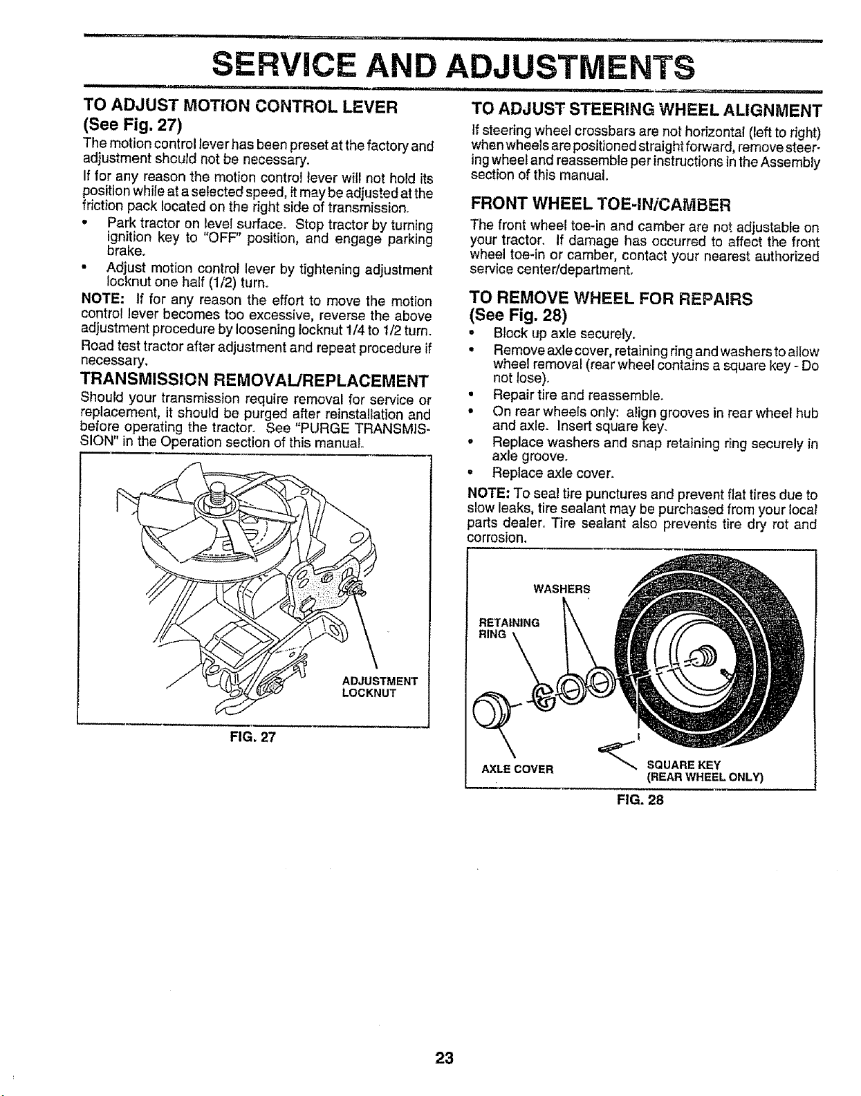
TO ADJUST MOTION CONTROL LEVER
(See Fig. 27)
The motion control lever has been preset at the factory and
adjustment should not be necessary_
If for any reason the motion control lever will not hold its
position while at a selected speed, it may be adjusted at the
friction pack located on the right side of transmission.
• Park tractor on level surface. Stop tractor by turning
ignition key to "OFF" position, and engage parking
brake.
• Adjust motion control lever by tightening adjustment
locknut one half (1/2) turn.,
NOTE: If for any reason the effort to move the motion
control lever becomes too excessive, reverse the above
adjustment procedure by loosening Iocknut 1/4 to 1/2 turn.
Road test tractor after adjustment and repeat procedure if
necessary.
TRANSMISSION REMOVAL/REPLACEMENT
Should your transmission require removal for service or
replacement, it should be purged after reinstallation and
before operating the tractor. See "PURGE TRANSMIS-
SION" in the Operation section of this manual
ADJUSTMENT
LOCKNUT
FIG. 27
TO ADJUST STEERING WHEEL ALIGNMENT
If steering wheel crossbars are not horizontal (left to right)
when wheels are positioned straightforward, remove steer-
ing wheel and reassemble per instructionsin the Assembly
section of this manual,
FRONT WHEEL TOE-IN/CAMBER
The front wheel toe-in and camber are not adjustable on
your tractor. If damage has occurred to affect the front
wheel toe-in or camber, contact your nearest authorized
service center!department.
TO REMOVE WHEEL FOR REPAIRS
(See Fig. 28)
,, Block up axle securely.
• Remove axle cover, retaining ring and washers to allow
wheel removal (rear wheel contains a square key - Do
not lose).
• Repair tire and reassemble°
• On rear wheels only: align grooves in rear wheel hub
and axle. Insert square key-
, Replace washers and snap retaining ring securely in
axle groove.
. Replace axle cover.
NOTE: To seal tire punctures and prevent flat tires due to
slow leaks, tire sealant may be purchased from your local
parts dealer° Tire sealant also prevents tire dry rot and
corrosion.
WASHERS
RETAINING
RING
AXLE COVER
!
SQUARE KEY
(REAR WHEEL ONLY)
FIG. 28
23
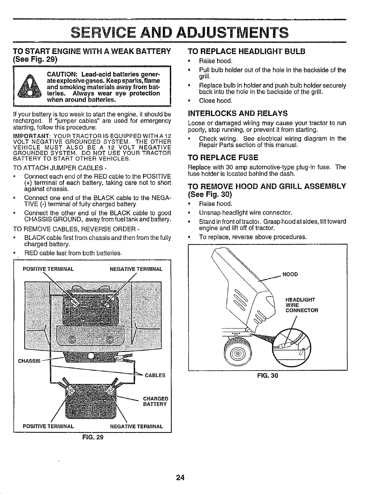
TO START ENGINE WiTH A WEAK BATTERY
(See Fig. 29)
A CAUTION: Lead-acid batteries gener-
Q ,_- _. ateexplosivegases. Keepsparks, flame
._ and smoking materials away from bat*
_ teries. Always wear eye protection
I -" when around batteries.
if your battery is too weak to start the engine, it should be
recharged, if "jumper cables" are used for emergency
starting, follow this procedure:
IMPORTANT: YOUR TRACTOR IS EQUIPPED WITH A 12
VOLT NEGATIVE GROUNDED SYSTEM. THE OTHER
VEHICLE MUST ALSO BE A 12 VOLT NEGATIVE
GROUNDED SYSTEM. DO NOT USE YOUR TRACTOR
BATTERY TO START OTHER VEHICLES.
TO ATTACH JUMPER CABLES -
, Connect each end of the RED cable to the POSITIVE
(+) terminal of each battery, taking care not to short
against chassis°
Connect one end of the BLACK cable to the NEGA-
TIVE (-) terminal of fully charged battery
• Connect the other end o_ the BLACK cable to good
CHASSIS GROUND, away from fuel tank and battery.
TO REMOVE CABLES, REVERSE ORDER -
• BLACK cable first from chassis and then from the fully
charged battery_
• RED cable last from both bakeries.
POSITIVE TERMINAL NEGATIVE TERMINAL
CHARGED
BATTERY
POSITIVE TERMINAL NEGATIVE TERMINAL
TO REPLACE HEADLIGHT BULB
• Raise hood°
= Pull bulb holder out of the hole in the backstde of the
grill
° Replace bulb in holder and push bulb holder securely
back into the hole in the backside of the gritl.
° Close hood.
INTERLOCKS AND RELAYS
Loose or damaged widng may cause your tractor to run
poorly, stop running, or prevent it from starting_
• Check wiring° See electrical wiring diagram in the
Repair Parts section of this manual
TO REPLACE FUSE
Replace with 30 amp automotive-type plug-in fuse. The
fuse holder is located behind the dash°
TO REMOVE HOOD AND GRILL ASSEMBLY
(See Fig. 30)
• Raise hood.
• Unsnap headlight wire connector.
• Stand in front of trsctoL G rasp hood at sides, tilt toward
engine and lift off of tractor.
• To replace, reverse above procedures.
HOOD
HEADLIGHT
WIRE
CONNECTOR
FIG. 30
FIG. 29
24
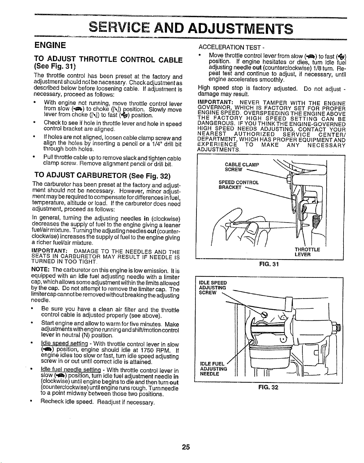
SERVICE AND ADJUSTMENTS
ENGINE ACCELERATION TEST-
TO ADJUST THROTTLE CONTROL CABLE
(See Fig. 31)
The throttle contro_ has been preset at the factory and
adjustment should not be necessary. Checkadjustment as
described below before loosening cables if adjustment is
necessary, proceed as follows:
• With engine not running, move throttle control lever
from slow (,,_) to choke (l\l) position. Slowly move
lever from choke (N) to fast (,_) position.
• Check to see if hole in throttle lever and hoFein speed
control bracket are aligned,
• If holes are not aligned, loosen cable clamp screw and
align the holes by inserting a pencil or a t/4" driil bit
through both holes°
• Pull throttle cable up to remove slack and tighten cable
clamp screw_ Remove alignment pencil or dritl bito
• Move throttle control lever from slow (,I_.) to fast (,,_)
position, If engine hesitates or dies, turn idle fuel
adjusting needle out (counterclockwise) 1/8 turn. Re-
peat test and continue to adjust, if necessary, until
engine accelerates smoothly.
High speed stop is factory adjusted. Do not adjust -
damage may result°
IMPORTANT: NEVER TAMPER W_TH THE ENGINE
GOVERNOR, WHICH iS FACTORY SET FOR PROPER
ENGINE SPEED OVERSPEED1NG THE ENGINE ABOVE
THE FACTORY HiGH SPEED SETTING CAN BE
DANGEROUS° IF YOU THINK THE ENGINE-GOVERNED
HIGH SPEED NEEDS ADJUSTING, CONTACT YOUR
NEAREST AUTHORIZED SERVICE CENTER/
DEPARTMENT, WHICH HAS PROPER EQUIPMENT AND
EXPERIENCE TO MAKE ANY NECESSARY
ADJUSTMENTS.
TO ADJUST CARBURETOR (See Fig. 32)
The carburetor has been preset at the factory and adjust-
ment should not be necessary. However, minor adjust_
ment may be required to compensate for differences in fuel,
temperature, altitude or loado If the carburetor does need
adjustment, proceed as follows:
in general, turning the adjusting needles in (clockwise)
decreases the supply of fuel to the engine giving a leaner
fueVair mixture. Turning the adjusting needles out (counter-
clockwise) increases the supply of fuel to the engine giving
a richer fuel/air mixture.
IMPORTANT: DAMAGE TO THE NEEDLES AND THE
SEATS IN CARBURETOR MAY RESULT IF NEEDLE IS
TURNED IN TOO TIGHT.
NOTE: The carburetor on this engine is low emission° It is
equipped with an idle fuel adjusting needle with a limiter
cap, which allows some adjustment within the limits allowed
by the cap. Do not attempt to remove the limiter cap, The
limiter cap cannot be removed witho utbreaking the adjusting
needle.
• Be sure you have a clean air filter and the throttle
control cable is adjusted properly (see above).
= Start engine and allow to warm for five minutes.. Make
adjustments with engine running and shift/motio ncontrol
lever in neutral (N) position.
• Idle speed setting - With throttle control lever in slow
(,_) position, engine should idle at 1750 RPM. If
engine idles too slow or fast, turn idle speed adjusting
screw in or out until correct idle is attained.
• .Id!_..._ue.Ineedle SettinQ - With throttle control lever in
slow (-ai.) position, turn idle fuel adjustment needle in
(clockwise) until engine begins to die and then turn out
(counterclockwise) until engine runs rough. Turn needle
to a point midway between those two positions.
, Recheck idle speed. Readjust if necessary_
CABLE CLAMP
SCREW
SPEED CONTROL
BRACKET
THROTTLE
LEVER
FIG. 31
IDLE SPEED
ADJUSTING
SCREW
IDLE FUEL / / _ '" -
ADJUSTING I J ]
NEEDLE tl IIr
FIG. 32
25
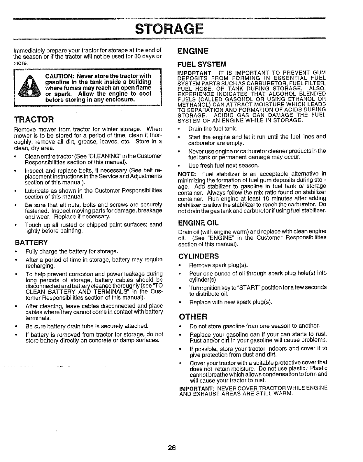
STO
Immediately prepare your tractor for storage at the end of ENGINE
the season or if the tractor will not be used for 30 days or
more°
I_ CAUTION: Never store the tractor with
gasoline in the tank inside a building
where fumes may reach an open flame
or spark. Allow the engine to coot
before storing in any enclosure.
TRACTOR
Remove mower from tractor for winter storage. When
mower is to be stored for a period of time, clean it thor-
oughly, remove all dirt, grease, leaves, etco Store in a
clean, dry area°
• CIeanentiretractor(See"CLEANING"intheCustomer
Responsibilities section of this manual).
o Inspect and replace belts, if necessary (See belt re-
placement instructions in the Service and Adjustments
section of this manual).
° Lubricate as shown in the Customer Responsibilities
section of this manual°
• Be sure that all nuts, bolts and screws are securely
fastened. Inspect moving parts for damage, breakage
and wear° Replace if necessary_
• Touch up all rusted or chipped paint surfaces; sand
lightly before painting.
BATTERY
° Fully charge the battery for storage.
• After a period of time in storage, battery may require
recharging.
, To help prevent corrosion and power leakage during
long periods of storage, battery cables should be
disconnected and battery cleaned thoroughly (see q'O
CLEAN BATTERY AND TERMINALS" in the Cus-
tomer Responsibilities section of this manual),
° After cleaning, leave cables disconnected and place
cables where they cannot come incontact with battery
terminals.
° Be sure battery drain tube is securely attached.
° If battery is removed from tractor for storage, do not
store battery directly on concrete or damp surfaces.
FUEL SYSTEM
IMPORTANT: iT IS IMPORTANT TO PREVENT GUM
DEPOSITS FROM FORMING IN ESSENTIAL FUEL
SYSTEM PARTS SUCH AS CARBURETOR, FUEL FILTER,
FUEL HOSE, OR TANK DURING STORAGE. ALSO,
EXPERIENCE INDICATES THAT ALCOHOL BLENDED
FUELS (CALLED GASOHOL OR USING ETHANOL OR
METHANOL) CAN ATTRACT MOISTURE WHICH LEADS
TO SEPARATION AND FORMATION OF ACIDS DURING
STORAGE. ACIDIC GAS CAN DAMAGE THE FLIEL
SYSTEM OF AN ENGINE WHILE IN STORAGE.
,, Drain the fuel tank.
= Start the engine and let it run until the fuel lines and
carburetor are empty.
, Never useengine orca_buretorcleaner products inthe
fuel tank or permanent damage may occur.
= Use fresh fuel next season.
NOTE: Fuel stabilizer is an acceptable alternative in
minimizing the formation of fuel gum deposits during stor-
age_ Add stabilizer to gasoline in fuet tank or storage
container. Always follow the mix ratio found on stabilizer
container. Run engine at least 10 minutes after adding
stabilizer to allow the stabilizer to reach the carburetor, Do
not d rain the gas tank and carburetor if using fuel stabilizer.
ENGINE OIL
Drain oil (with engine warm) and replace with clean engine
oil (See "ENGINE" in the Customer Responsibilities
section of this manual).
CYLINDERS
- Remove spark plug(s)..
- Pour one ounce of oil through spark plug hole(s) into
cylinder(s).
• Turn ignitionkey to"START" position for a few seconds
to distribute oil.
° Replace with new spark plug(s).
OTHER
• Do not store gasoline from one season to another.
° Replace your gasoline can if your can starts to rust.
Rust and/or dirt in your gasoline will cause problemso
° If possible, store your tractor indoors and cover it to
give protection from dust and dirt.
, Cover your tractor with a suitable protective cover that
does not retain moisture: DO not use plastic. Plastic
cannot breathe which allows condensation to form and
will cause your tractor to rust.
IMPORTANT: NEVER COVER TRACTOR WHILE ENGINE
AND EXHAUST AREAS ARE STILL WARM.
26

TROUBLESHOOTING
POINTS
i.,,' ,i......... ,,,,,, ,,, ,:::
PROBLEM
iiiiiiii , i,
Will not start
Hard to start
iiiiiiii iii
Engine will not turn over
i,,,i,iiii,i ,i,, i
Engine clicks but will not
start
Loss of power
i,iiii i
Excessive vibration
CAUSE
_r ........ IIIr'l"'ll I I'111III
1, Out offuef
2 Engine not "CHOKED" propariy_
3_ Engine flooded,
4. Bad spark plug
5 Dirty air filter.
6, Dirty fuel tilter.
7, Water in fuel
8, Loose or damaged wir}ng
9, Carburetor out of adjustment
10, Engine valves out of adjustment,
,,11,,
1. Dirt3, air fiffer.
2_ Bad spark plug.
3- Weak or dead battery.
4 Dirty fuel tilter,
5 Stale or dirty fuel,
6, Loose or damaged wiring
7 Carburetor out of adjustmenL
8. Engine valves out of adjustment.
_L'llllll.... I1''111 '111II "M '1
1 C{utch/brake pedal not depressed.
2 Attachment clutch is engaged
3, Weak or dead battery,
4. Blown fuse,
5 Corroded battery terminals
6, Loose or damaged wiring
7 Faulty ignition switch.
8, Faulty solenoid or starter.
9. Faulty operator presence switch(es)_
1 Weak or dead battery.
2. Corroded battery terminals,
3 Loose or damaged wiring.
4 Faulty solenoid or starter.
1, Cutting too much grass/too fast°
2. Throttle in "CHOKE" position.
3 Build-up of grass, leaves and trash under mower.
4 Dirty air filter,
5. Low otl level/dirty oil
6, Fault,,, spark plug
7, Dirty fuel filter
8. Stale or dirty fuel,,
9 Water in fuel_
10. Spark plug wire loose
11. Dirty engine air screen/fins .....
12 Dirty/clogged muffler,
13 Loose or damaged wiring
14_ Carburetor out of adiustment
t5, Engine valves out of adjustment,
ii , ii ,11111i i
1,, Worn, bent or loose blade
2, Bent blade mandrel
3. Loose/damaged part(s),
CORRECTION
1, Fill fuel tank
2. See "TO START ENGINE" in Operation section,
3, Wait severer minutes before attempting to start
4 Replace spark plug
5. Clean/replace air filter.
6. Replace fueF fitter,
7 Drain fuel tank and carburetor, refill tank w_th fresh
gasoline and replace fuel fitter
8, Check eli wiring.
9, See "To Adjust Carburetor" in Service Adjustments
section
10. Contact an authorized service center/departmento
i1,,,i,1,1,,11,,, ,........
I Clean/replace air filter.
2, Replace spark plug.,
3, Recharge or replace battery
4. Replace fuel tilter,
5. Drain fuel tank and reffif wilh fresh gasoline,
6. Check a{l wiring.
7, See "To Adjust Carburetor" In Service Adjustments
section,
8. Contact an authorized service center/departmenL
t4 Depress clutch/brake pedal,
2. Disengage attachment clutch
3 Recharge or replace battery,
4 Replace fuse
5_ Clean battery terminals,
6. Check all widngo
7. Checldreptace ignition switch.
8. Check]replace solenoid or starter.
9, Contactan authorized service centerldepartment.
1. Recharge or replace battery.
2 Clean battery terminals
3. Check all wiring
4 Check/repiace sorenoid or starter.
1, Set in "Higher Cut" position!reduce speed
2 Adjust throttle control
3 Clean underside of mower housing.
4, Clean/reptace air filter.,
5. Check oil level/change oil,
6_ Clean and regap or change spark ptug.
7. Replace fuel filter.
8. Drain fuel tank and refi{I with fresh gasoline,
9. Drain fuel tank and carburetor, retili tank with fresh
gasoline and replace fuet filter,
10 Connect and tighten spark plug wire.
11_ Clean engine air screen/fins
12, Clean!replace muffler,,
13, Check all wiring,
14, See "To Adjust Carburetor" in Service Adjustments
section.
15, Contact an authorized service centerldapartment,
t, Replace blade Tighten blade bolt
2_ Replace blade mandrel.
3 Tighten loose part(s) Replace damaged parts.
27

TROUBLESHOOTING POINTS
PROBLEM
Engine continues to run
when operator leaves seat
with attachment clutch
engaged
Poorcut-uneven
Mower blades wili not
rotate
Poor grass discharge
Headlight(s) not working
(if so equipped)
Battery will not charge
Loss of drive
CAUSE CORRECTION
1. FauIty operator-safety presence control system
Engine "backfires"
when turning engine
"OFF" .....
1- Worn, bent or loose blade,
2. Mower deck not level
3. Buildup of grass, leaves, and trash under mower
4 Bent blade mandrel.
5 Clogged mower deck vent holes from buildup of
grass, leaves, and trash around mandrels,
2
3
4
5,
6
7.
8,,
9.
10,
11,
1 Check wiring, switches and connections. If not
corrected, contact an authorized service center/
department
1, Replace blade Tighten blade bolt,
2. Level mower deck,
3 Clean underside of mower housing
4, Replace blade mandrel,
5, Clean around mandrels to open vent holes,
1, Obstruction in clutch mechanism
2. Worn/damaged mower drive belt
3 Frozen idler pulley
4 Frozen blade msndre!,
Engine speed too slow,
Travel speed too fast
Wet grass,
Mower deck not leve!,,
Low/uneven tire air pressure.
Worn, bent or loose blade.
1, Remove obstruction.
2. Replace mower drive belt
3 Replace Idler pulley
4, Replace blade mandrel.
1 Piece throttle control in "FAST" position
2 Shift to slower speed.
3 Allow grass to dry before mowing.
4, Level mowerdeck
5. Check tires for proper air pressure,
6. Replacetsharpen blade,, Tighten blade bolt.
Buildup of grass, leaves and trash under mower,
Mower drive belt worn,
Blades improperly installed,
Improper blades used.
Clogged mower deck vent holes from buildup of
grass, leaves, and trash around mandrels
l r switch iS "OFF'r
2' Bulb(s) burned out.
3 Faulty light switch.
4. Loose or damaged wiring.
5, Blown fuse,,
1 Bad battery cell(s),
2 Poor cable connections.
3 Faulty regulator (if so equipped)
4. Faulty alternator
1, Freewheel control in "disengaged" position
2 Motion drive belt worn, damaged, or broken,
3, Air trapped in transmission during shipment
or servicing,
1. Engine throttle control net set at =SLOW"
position for 30 seconds before stopping engine
7 Clean underside of mower housing
8. Replace mower drive belt,
9, Reinstall blades sharp edge down.
10, Replace with blades listed in this manual,,
11, Clean around mandrels to open vent holes
1 Turn switcli "ON"
2. Replace bulb(s),
3 ChecWrepiace light switch
4, Check widng and connections,
5, Replace fuse
1. Replace battery,
2, Check/clean all connections
3, Replace regulator
4 Reptace alternator
1. Place freewheel cent[el in "engaged" positiOnr
2 Replace motion drive belt
3, Purge transmission
I Move thro_e control to "SLOW" position and altow
to Idle for 30 seconds before stopping engine.
28
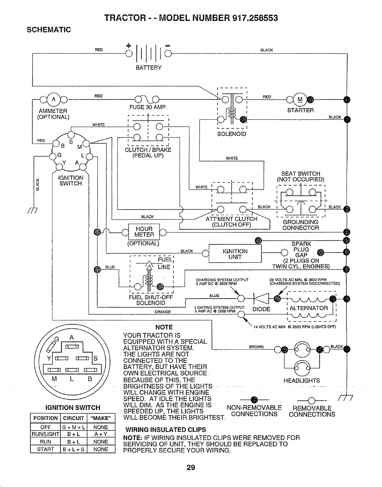
SCHEMATIC
TRACTOR - - MODEL NUMBER 917.258553
RED
0111o
BATTERY
SLACK
__ RED
AMMETER
(OPTIONAL)
WHITE
/__ SWITCH
IGNITION SWITCH
POSITION CIRCUIT "MAKE"
OFF G + M + L NONE
RUN/LIGHT B + L A + Y
RUN B+ L NONE
START IB+L+S NONE
FUSE 30 AMP.
t I
I-(3 0
L ....... J
CLUTCH / BRAKE
(PEDAL UP)
BLACK
___ HOURMETER
(OPTIONAL)
BLACK
r ........ t
J ___/k_FUEL_
1 'Z_" LINE'
1 I
I I
FUELSHUT-OFF.
_______ SOLENOID1
ORANGE
, RED D
iiL_ STARTER sLAcK
..... J
l WHITE
o ooo0P, O
WHITE I _ I l I
I 7 I--
I _ I
___.__ (_ , BLACK _ I _LACK
(CLUTCH OFF) ! GROUNDING
CONNECTOR
)
(_ IGNITION _ PLUG
UNIT I _ GAP _' _ )
J (2 PLUGS ON
TWIN CYL. ENGINES) _
NOTE
YOUR TRACTOR IS
EQUIPPED WITH A SPECIAL
ALTERNATOR SYSTEM.
THE LIGHTS ARE NOT
CONNECTED TO THE
BATTERY, BUT HAVE THEIR
OWN ELECTRICAL SOURCE.
BECAUSE OF THIS, THE
BRIGHTNESS OF THELIGHTS
WILL CHANGE WITH ENGINE
SPEED, AT IDLE THE LIGHTS
WILL DIM. AS THE ENGINE IS
SPEEDED UP, THE LIGHTS
WILL BECOME THEIR BRIGHTEST.
CHARGING SYSTEM OUTPUT 28 VOLTS AC MIN, @ 3600 RPM
3 AMP DO @ 31800 RFM (CHARGING SYSTEM D_SCONNECTED}
BLUE _iI_ - _
BROWN
HEADLIGHTS
A
w
NON-REMOVABLE
CONNECTIONS
©
REMOVABLE
CONNECTIONS
WIRING INSULATED CLIPS
NOTE: IF WIRING INSULATED CLIPS WERE REMOVED FOR
SERVICING OF UNIT, THEY SHOULD BE REPLACED TO
PROPERLY SECURE YOUR WIRING.
/_7
29
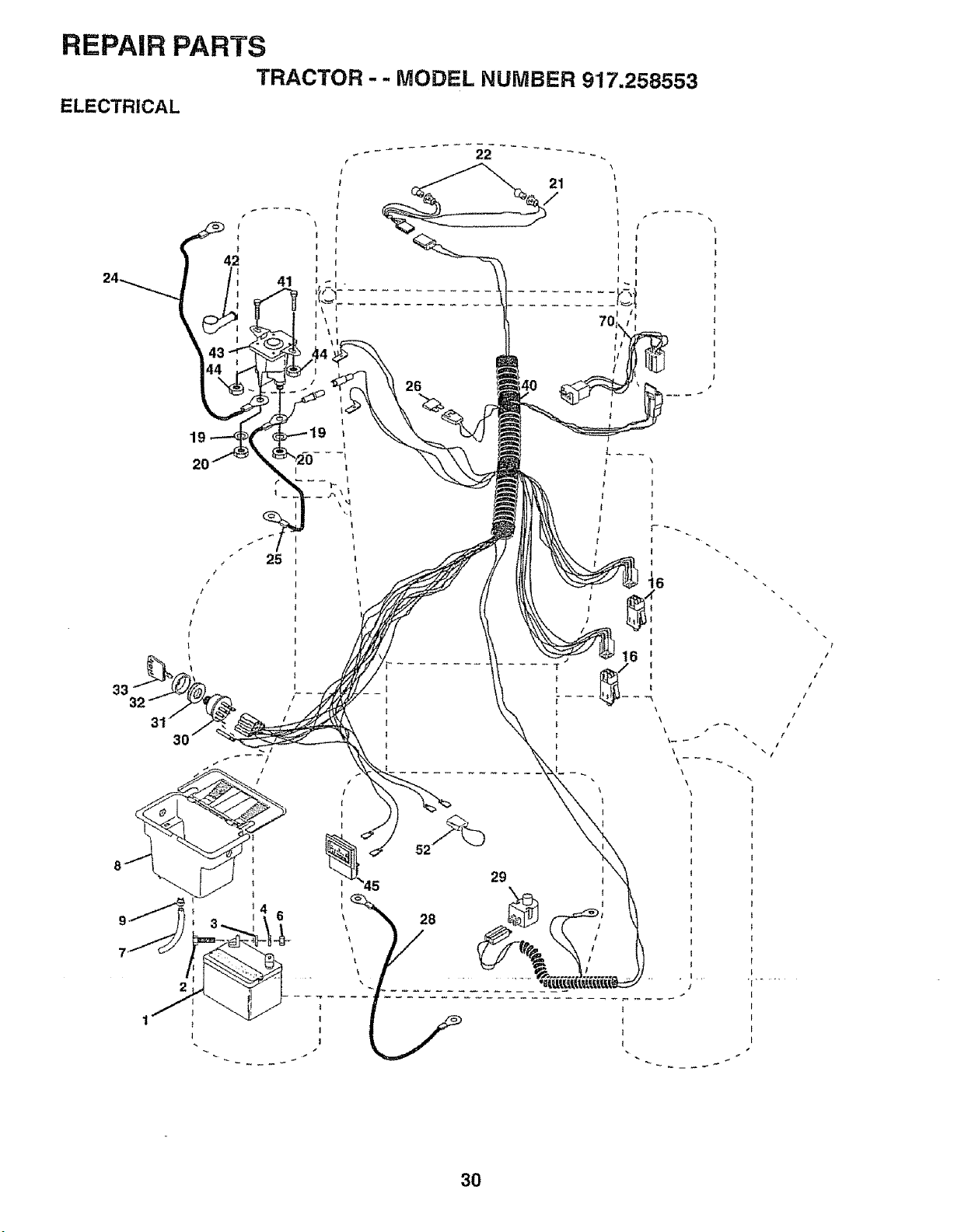
REPAIR PARTS
TRACTOR -- MODEL NUMBER 917.258553
ELECTRICAL
-- .... 22 --- -.
21
26
33
2O
30
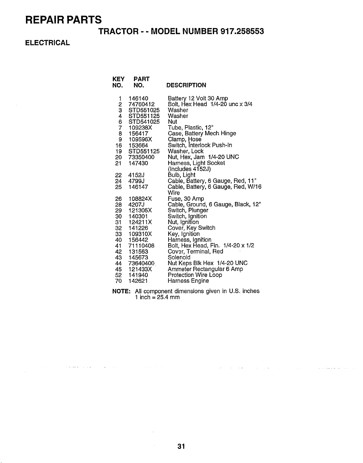
REPAIR PARTS
TRACTOR - - MODEL NUMBER 917.258553
ELECTRICAL
KEY PART
NO. NO. DESCRIPTION
1 146140
2 74760412
3 STD551025
4 STD551125
6 STD541025
7 109238X
8 156417
9 't09596X
16 153664
19 STD551125
20 73350400
21 147430
22 4152J
24 4799J
25 146147
26 108824X
28 4207J
29 121305X
30 140301
31 124211X
32 141226
33 109310X
40 156442
41 71110408
42 131563
43 145673
44 736404O0
45 121433X
52 141940
70 142621
Battery 12 Volt 30 Amp
Bolt, Hex Head 1/4-20 unc x 3/4
Washer
Washer
Nut
Tube, Plastic, 12"
Case, Battery Mech Hinge
Clamp, Hose
Switch, Tnterlock Push-In
Washer, Lock
Nut, Hex, Jam 1/4-20 UNC
Harness, Light Socket
(Includes 4152J)
Bulb, Light
Cable, Battery, 6 Gauge, Red, 11"
Cable, Battery, 6 Gauge, Red, W/16
Wire
Fuse, 30 Amp
Cable, Ground, 6 Gauge, Black, 12"
Switch, Plunger
Switch, Ignition
Nut, Ignition
Cover, Key Switch
Key, Ignition
Harness, Ignition
Bolt, Hex Head, Fin° 1/4-20 x 1/2
Cowr, Terminal, Red
Solenoid
Nut Keps Blk Hex 114_20 UNC
Ammeter Rectangular 6 Amp
Protection Wire Loop
Harness Engine
NOTE: All component dimensions given in U.S. inches
1 inch = 25_4 mm
31
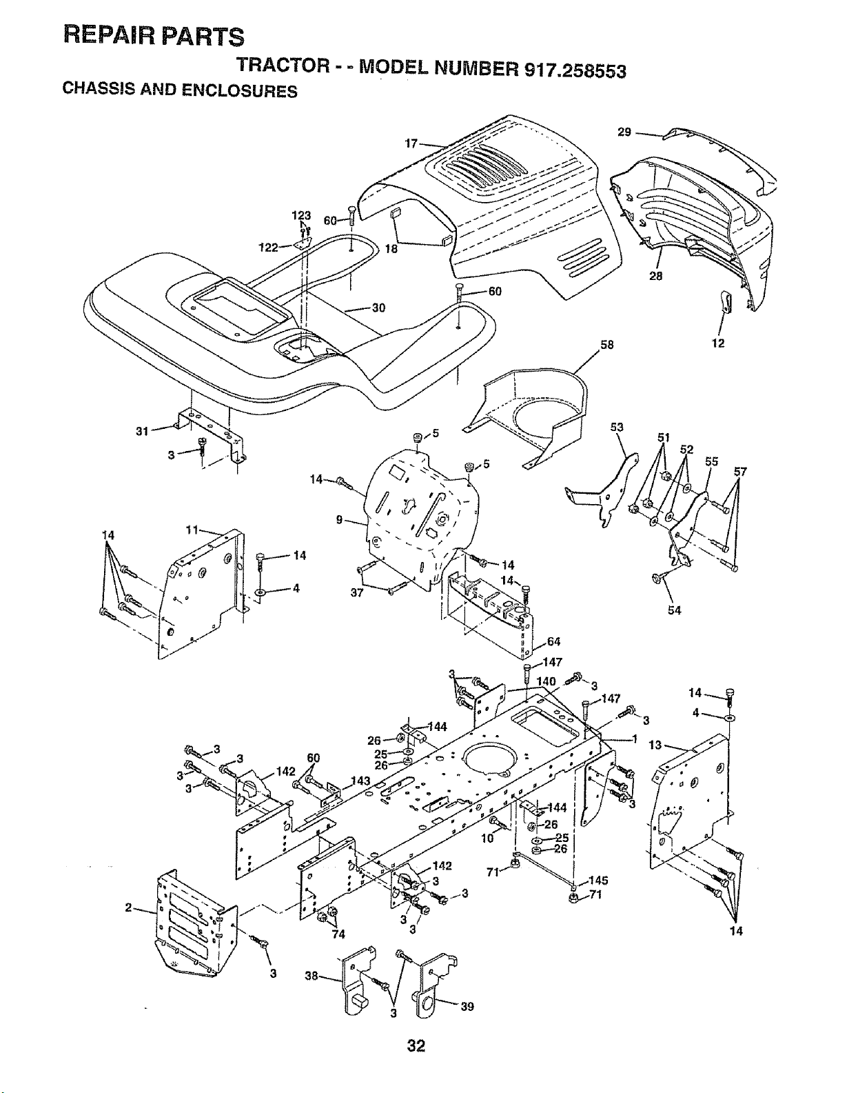
REPAIR PARTS
TRACTOR - - MODEL NUMBER 917.258553
CHASS!S AND ENCLOSURES
29
28
58 12
14
31
37
14
53
2 55 7
54
6O
3
10
71
14
32
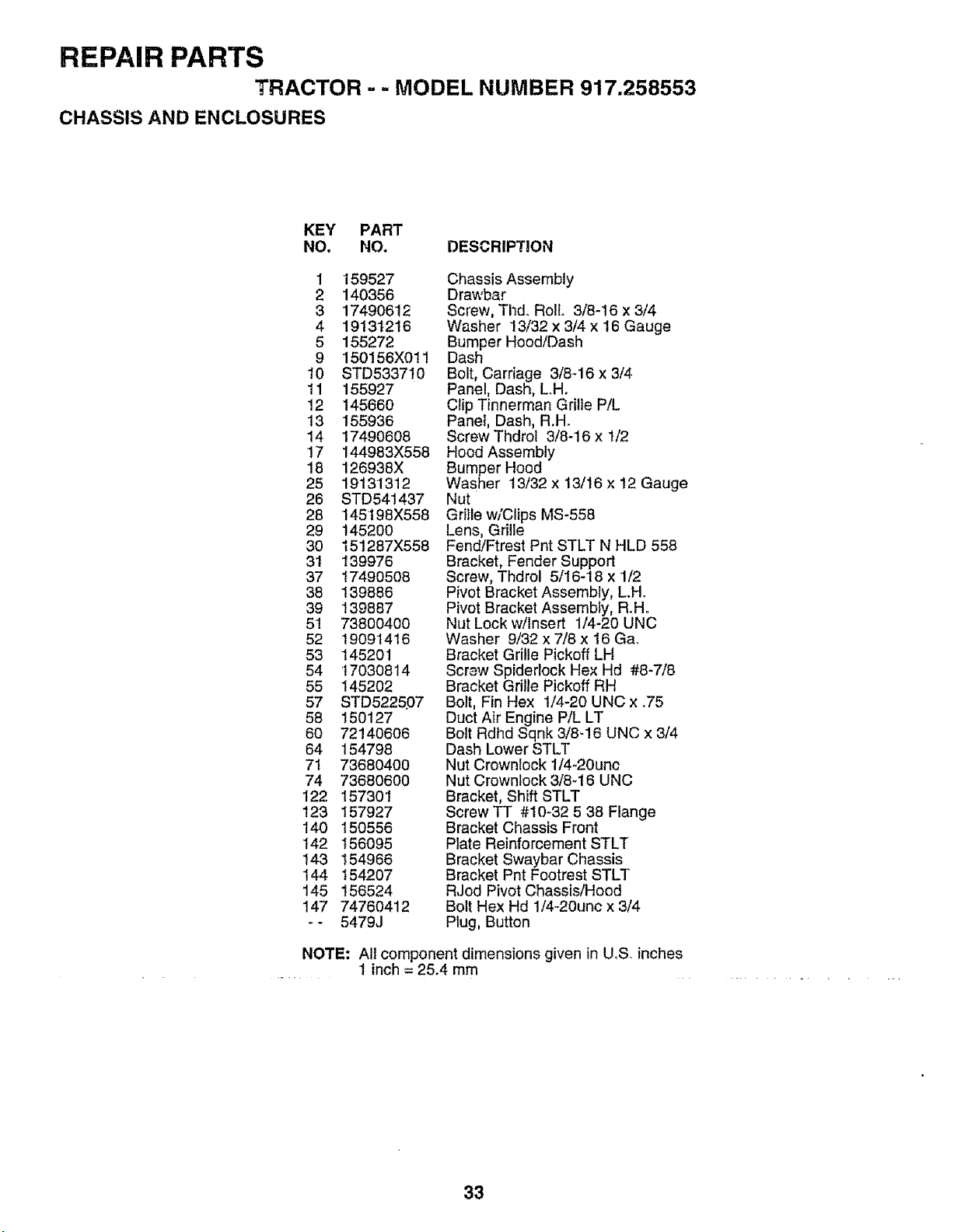
REPAIR PARTS
TRACTOR -- MODEL NUMBER 917.258553
CHASSIS AND ENCLOSURES
KEY PART
NO. NO. DESCRIPTION
1 159527
2 140356
3 17490612
4 19131216
5 155272
9 150156X011
10 STD533710
11 155927
12 145660
13 155936
14 '17490608
17 144983X558
18 126938X
25 19131312
26 STD541437
28 145t98X558
29 145200
30 t51287X558
31 139976
37 17490508
38 139886
39 139887
51 73800400
52 19091416
53 145201
54 '17030814
55 145202
57 STD5225P7
58 150127
60 72140606
64 154798
71 73680400
74 73680600
122 157301
123 157927
140 150556
142 156095
143 154966
144 154207
145 156524
147 74760412
_- 5479J
Chassis Assembly
Drawbar
Screw, Thd° Roll. 3/8-16 x 3/4
Washer 13/32 x 3/4 x 16 Gauge
Bumper Hood/Dash
Dash
Bolt, Carriage 3/8-16 x 3/4.
Panel, Dash, L.H.
Clip Tinnerman Grille P/L
Panel, Dash, R.H.
ScrewThdrot 3/8-16 x 1/2
Hood Assembly
Bumper Hood
Washer t 3/32 x 13/! 6 x 12 Gauge
Nut
Grille w/Clips MS-558
Lens, Grille
Fend/Ftrest Pnt STLT N HLD 558
Bracket, Fender Support
Screw, Thdrol 5/16-18 x 1/2
Pivot Bracket Assembly, L.H.
Pivot Bracket Assembly, R°H°
Nut Lock w/Insert 1/4-20 UNC
Washer 9/32 x 7/8 x 16 Ga_
Bracket Grille Pickoff LH
Screw Spiderleck Hex Hd #8-7/8
Bracket Grille Pickoff RH
Bolt, Fin Hex 1/4-20 UNC x .75
Duct Air Engine P/L LT
Bolt Rdhd Sqnk 3/8-!6 UNC x 3/4
Dash Lower STLT
Nut Crownlock 1/4-20unc
Nut Crownlock 3/8d 6 UNC
Bracket, Shift STLT
Screw TT #10-32 5 38 Flange
Bracket Chassis Front
Plate Reinforcement STLT
Bracket Swaybar Chassis
Bracket Pnt Footrest STLT
RJod Pivot Chassis/Hood
Bolt Hex Hd 1/4-20unc x 3/4
Plug, Button
NOTE: All component dimensions given in U,S,. inches
1 inch = 25.4 mm
33
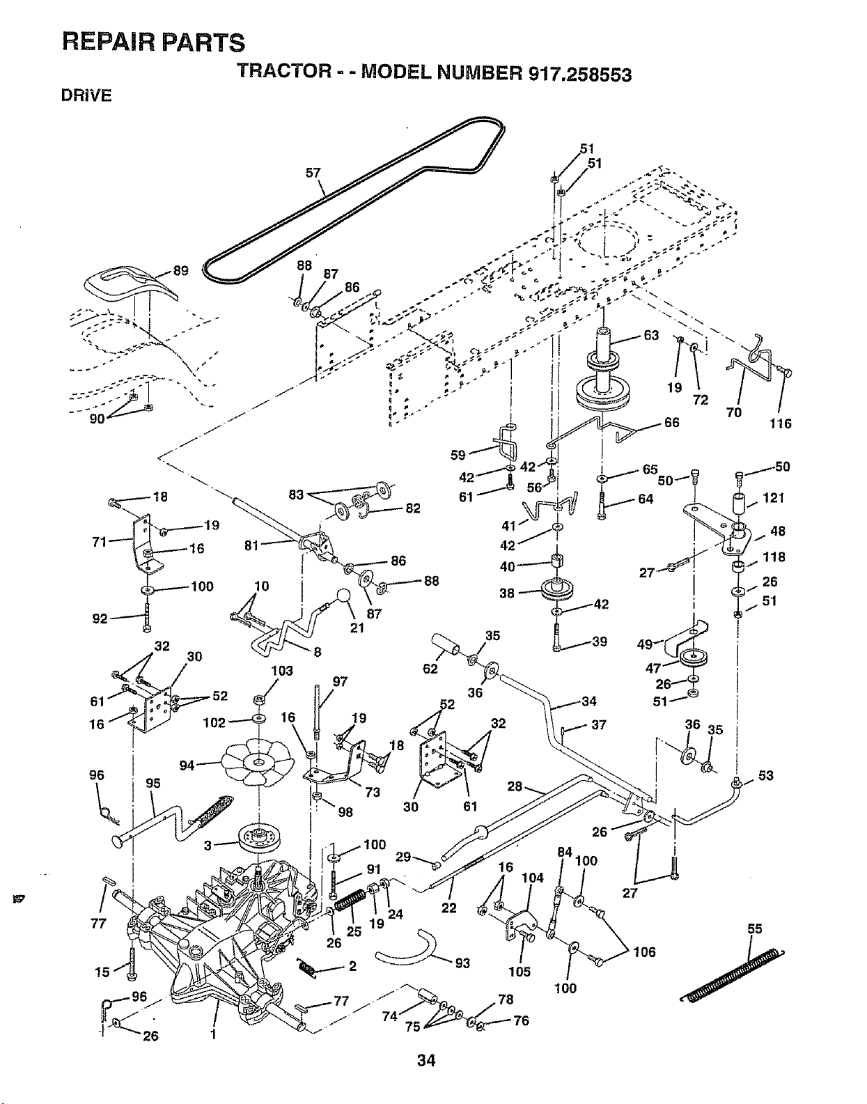
REPAIR PARTS
TRACTOR - - MODEL NUMBER 917.258553
DRIVE
34
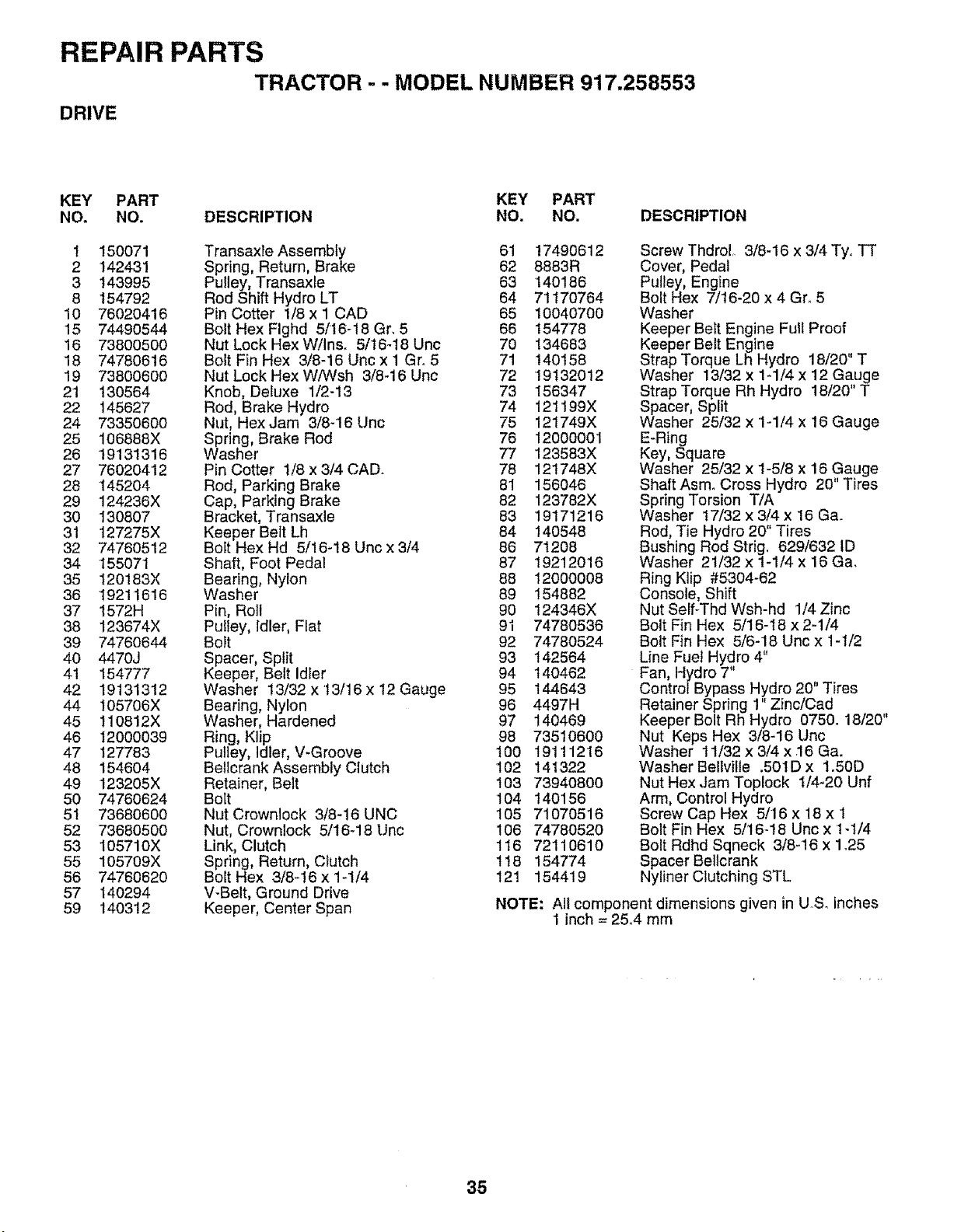
REPAIR PARTS
TRACTOR - - MODEL NUMBER 917.258553
DRIVE
KEY PART KEY PART
NO. NO. DESCRIPTION NO. NO. DESCRIPTION
1 150071 Transaxie Assembly 61 17490612
2 142431 Spring, Return, Brake 62 8883R
3 143995 Pulley, Transaxle 63 140186
8 154792 Rod Shift Hydro LT 64 71t70764
10 76020416 Pin Cotter 1/8 x 1 CAD 65 10040700
15 74490544 Bolt Hex Flghd 5/'16-18 Gr, 5 66 154778
16 73800500 Nut Lock HexW!Ins. 5/16-18 Unc 70 134683
18 74780616 Bolt Fin Hex 3/8-16 Uric x 1 Gr_ 5 71 140158
19 73800600 Nut Lock Hex W/Wsh 3/8-16 Unc 72 19132012
21 130564 Knob, Deluxe 1/2-13 73 156347
22 145627 Rod, Brake Hydro 74 121199X
24 73350600 Nut, Hex Jam 3/8-16 Unc 75 121749X
25 106888X Spring, Brake Rod 76 12000001
26 t9131316 Washer 77 123583X
27 76020412 Pin Cotter 1/8 x 3/4 CAD_ 78 121748X
28 145204 Rod, Parking Brake 81 156046
29 124236X Cap, Parking Brake 82 123782X
30 130807 Bracket, Transaxle 83 19171216
31 127275X Keeper Belt Lh 84 140548
32 74760512 Bolt HexHd 5/16-18 Unc x3/4 86 71208
34 155071 Shaft, Foot Pedal 87 19212016
35 t20183X Bearing, Nylon 88 12000008
36 t9211616 Washer 89 154882
37 1572H Pin, Roll 90 124346X
38 123674X Pulley, Idler, Flat 91 74780536
39 74760644 Bolt 92 74780524
40 4470J Spacer, Split 93 142564
41 154777 Keeper, Belt Idler 94 140462
42 19131312 Washer 13/32 x13/16 x 12 Gauge 95 144643
44 105706X Bearing, Nylon 96 4497H
45 110812X Washer, Hardened 97 140469
46 12000039 Ring, Klip 98 735t0600
47 127783 Pulley, Idler, V-Groove 100 19111216
48 154604 BetlcrankAssembly Clutch 102 141322
49 123205X Retainer, Belt 103 73940800
50 74760624 Bolt 104 140156
5t 73680600 Nut Crownlock 3/8-16 UNC 105 71070516
52 73680500 Nut, Crownlock 5/16-18 Unc 106 74780520
53 105710X Link, Clutch 116 72110610
55 105709X Spring, Return, Clutch 118 154774
56 74760620 Bolt Hex 3/8-16 x 1-1/4 121 154419
57 140294 V-Belt, Ground Drive
59 140312 Keeper, Center Span
Screw Thdrol. 3/8-16 x 3/4 Tyo TT
Cover, Pedal
Pulley, Engine
Bolt Hex 7/t6-20 x 4 Gr. 5
Washer
Keeper Belt Engine Full Proof
Keeper Belt Engine
Strap Torque Lh Hydro 18/20" T
Washer 13/32 x 1-1/4 x 12 Gauge
Strap Torque Rh Hydro 18/20" T
Spacer, Split
Washer 25/32 x '1-1/4 x 16 Gauge
E-Ring
Key, Square
Washer 25/32 x 1-5/8 x 16 Gauge
Shaft Asmo Cross Hydro 20" Tires
Spring Torsion T/A
Washer t7/32 x 3/4 x 16 Ga.
Rod, Tie Hydro 20" Tires
Bushing Rod Strig, 629/632 ID
Washer 21/32 x 1-1/4 x 16 Ga.
Ring Klip #5304-62
Console, Shift
Nut Self-Thd Wsh-hd 1/4 Zinc
Bolt Fin Hex 5/16-18 x 2-1/4
Bolt Fin Hex 5/6-18 Unc x 1 -t/2
Line Fuel Hydro 4"
Fan, Hydro 7"
Control Bypass Hydro 20" Tires
., -7_ /Cad
Retainer Spring J ...'nc
Keeper Bolt Rh Hydro 0750.18/20"
Nut Keps Hex 3/8-16 Uric
Washer 11/32 x 3/4 x _16Ga.
Washer Beltville .501D x 1.50D
Nut Hex Jam Toplock 1/4-20 Unf
Arm, Control Hydro
Screw Cap Hex 5/16 x 18 x I
Bolt Fin Hex 5/16-18 Unc x 1-1/4
Bolt Rdhd Sqneck 3/8-!6 x 1_25
Spacer Belicrank
Nyliner Clutching STL
NOTE: All component dimensions given in U.So inches
1 inch = 25,.4 mm
35
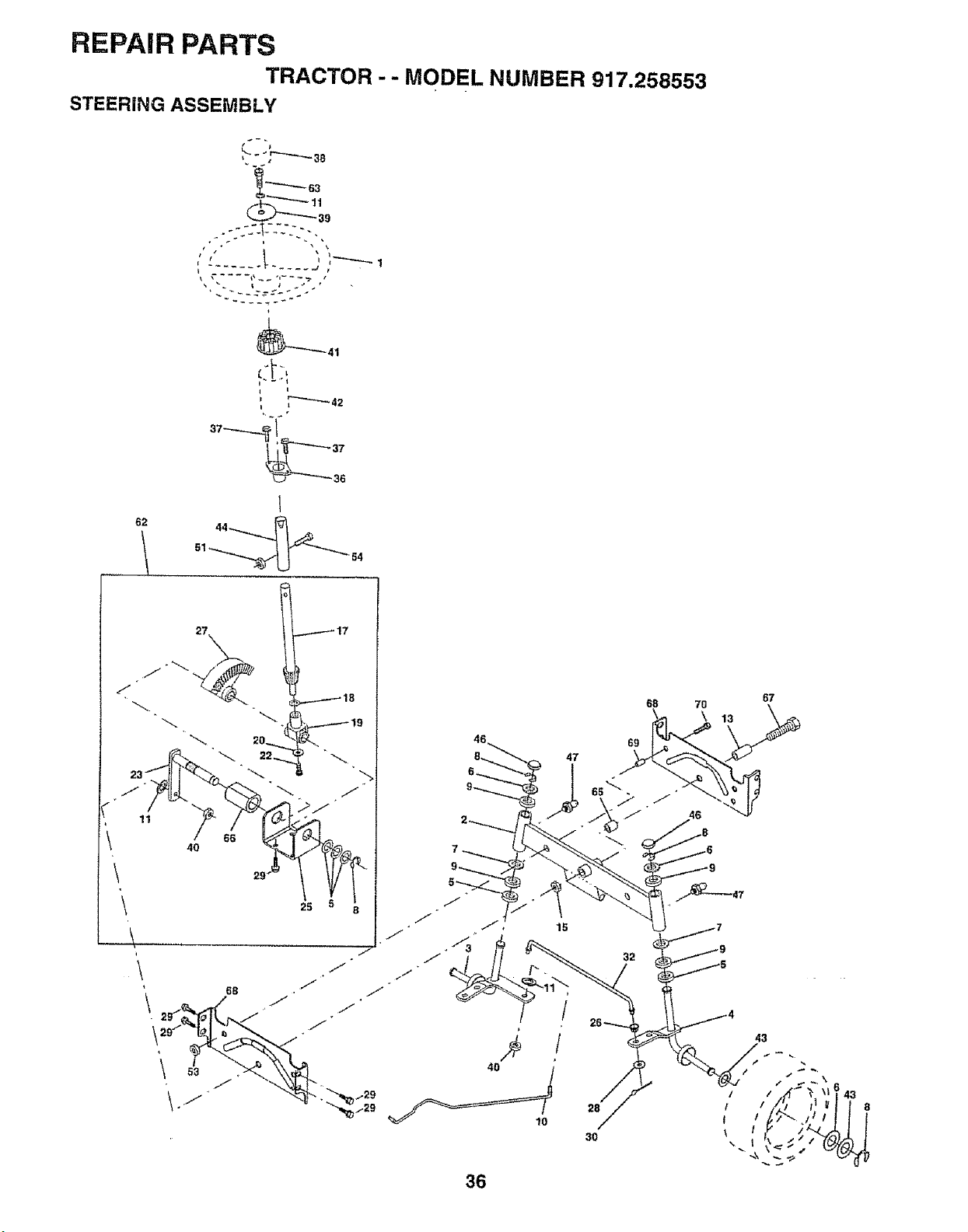
REPAIR PARTS
TRACTOR - - MODEL NUMBER 917.258553
STEERING ASSEMBLY
62
, 11
\
\
\
\
t _- -j
"_63
I t
_ 66
40
\
67
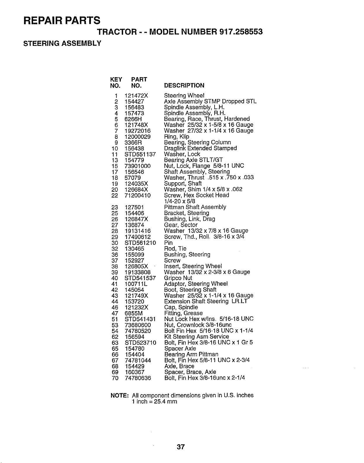
REPAIR PARTS
TRACTOR - - MODEL NUMBER 917.258553
STEERING ASSEMBLY
KEY PART
NO. NO. DESCRIPTION
I 121472X
2 154427
3 156483
4 157473
5 6266H
6 121748X
7 19272016
8 12000029
9 3366R
10 156438
11 STD551137
13 154779
15 73901000
17 156546
18 57079
19 124035X
20 126684X
22 71200410
23 127501
25 154406
26 126847X
27 136874
28 19131416
29 17490612
3O STD561210
32 130465
36 155099
37 152927
38 126805X
39 19133808
40 STD541537
41 100711L
42 145054
43 12!749X
44 153720
46 121232X
47 6855M
51 STD541431
53 73680600
54 74780520
62 156594
63 STD523710
65 154780
66 1544O4
67 74781O44
68 154429
69 160367
70 74780636
Steering Wheel
Axle Assembly STMP Dropped STL
Spindle Assembly, L.H.
Spindle Assembly, R_H.
Bearing, Race, Thrust, Hardened
Washer 25/32 x 1-5/8 x 16 Gauge
Washer 27/32 x 1-1/4 x 16 Gauge
Ring, Klip
Bearing, Steering Column
Draglink Extended Stamped
Washer, Lock
Bearing Axle STLT/GT
Nut, Lock, Flange 5/8-1t UNC
Shaft Assembly, Steering
Washer, Thrust .515 x .750 x .033
Support, Shaft
Washer, Shim 1/4 x 5/8 x .062
Screw, Hex Socket Head
1/4-20 x 5/8
Pittman Shaft Assembly
Bracket, Steering
Bushing, Link, Drag
Gear, Sector
Washer 13/32 x 7/8 x 16 Gauge
Screw, Thd., Rollo 3/8-16 x 3/4
Pin
Rod, Tie
Bushing, Steering
Screw
Insert, Steering Wheel
Washer 13/32 x 2-3/8 x 8 Gauge
Gripco Nut
Adaptor, Steering Wheel
Boot, Steering Shaft
Washer 25/32 x 1-1/4 x 16 Gauge
Extension Shaft Steering LRoLT
Cap, Spindle
Fitting, Grease
Nut Lock Hex w/Ins. 5/16-18 UNC
Nut, Crownlock 3/8-16unc
Bolt Fin Hex 5/16-18 UNC x 1-1/4
Kit Steering Asm Service
Bolt, Fin Hex 3/8-16 UNC x 1 Gr 5
Spacer Axle
Bearing Arm Pittman
Bolt, Fin Hex 5/8-11 UNC x 2-3/4
Axle, Brace
Spacer, Brace, Axle
Bolt, Fin Hex 3/8-16unc x 2-1/4
NOTE: All component dimensions given in U.S. inches
1 inch = 25°4 mm
37
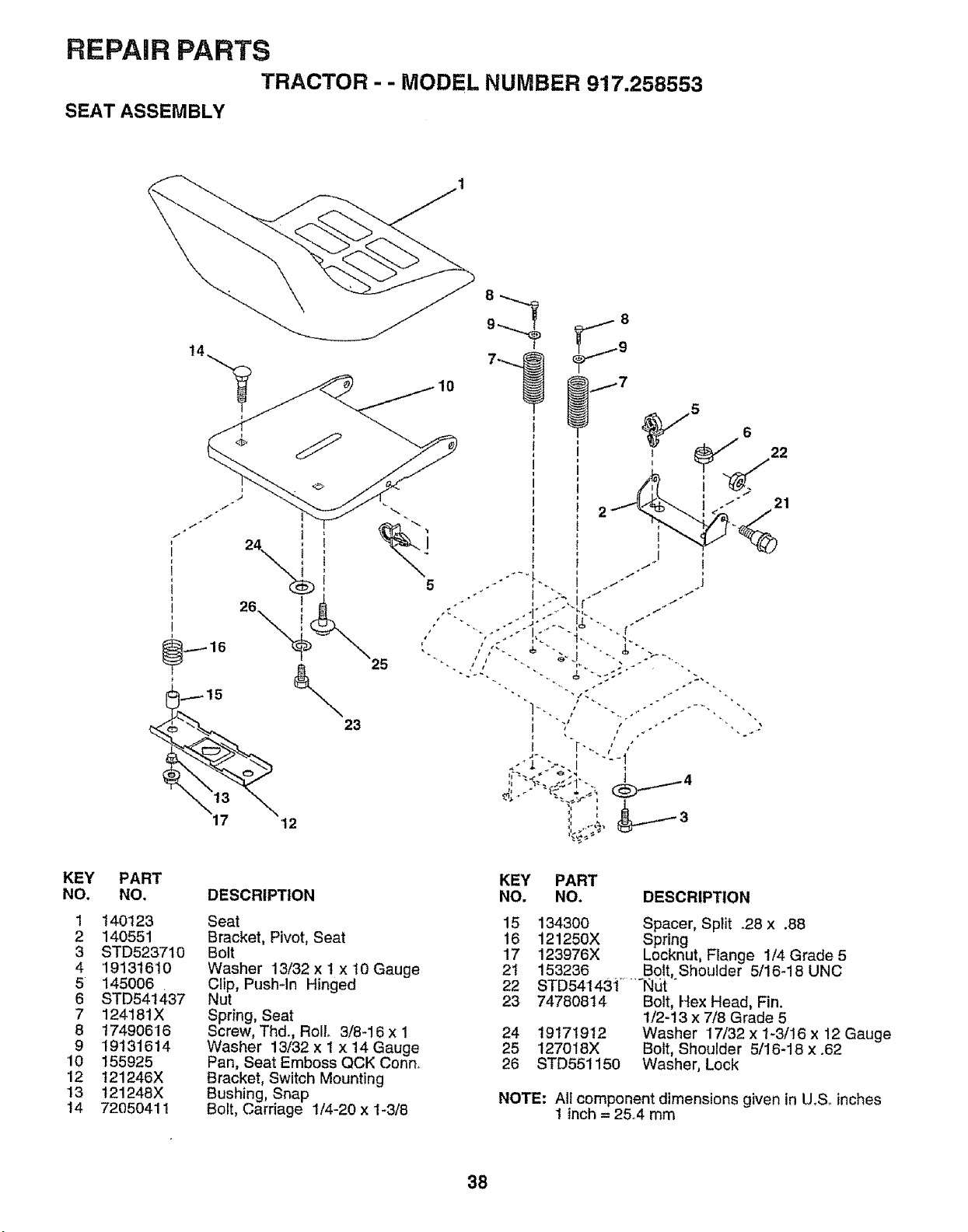
REPAIR PARTS
TRACTOR - - MODEL NUMBER 917.258553
SEAT ASSEMBLY
KEY
NO.
1
2
3
4
5
6
7
8
9
10
12
13
14
23
5
PART
NO.
140123
140551
STD523710
'1913t6'10
145006
STD541437
124181X
17490616
19131614
155925
t21246X
t21248X
72O50411
DESCRIPTION
Seat
Bracket, Pivot, Seat
Bolt
Washer 13/32 x ! x 10 Gauge
Clip, Pushqn Hinged
Nut
Spring, Seat
Screw, Thd., Roll 3/8-16 x 1
Washer 13/32 x 1 x 14 Gauge
Pan, Seat Emboss QCK Conn_
Bracket, Switch Mounting
Bushing, Snap
Bolt, Carriage 1/4-20 x 1-3/8
KEY PART
NO. NO. DESCRIPTION
15 134300 Spacer, Split _28 x .88
16 121250X Spring
17 123976X Lecknut, Flange 1/4 Grade 5
21 153236 Bolt, Shoulder 5/16-18 UNC
22 STD541431 ..... Nut "
23 74780814 Bolt, Hex Head, Fin.
1/2-13 x 7/8 Grade 5
24 19171912 Washer 17/32 x 1-3/16 x 12 Gauge
25 127018X Bolt, Shoulder 5/16-18 x.62
26 STD551150 Washer, Lock
NOTE: All component dimensions given in U.S. inches
1 inch = 25°4 mm
38
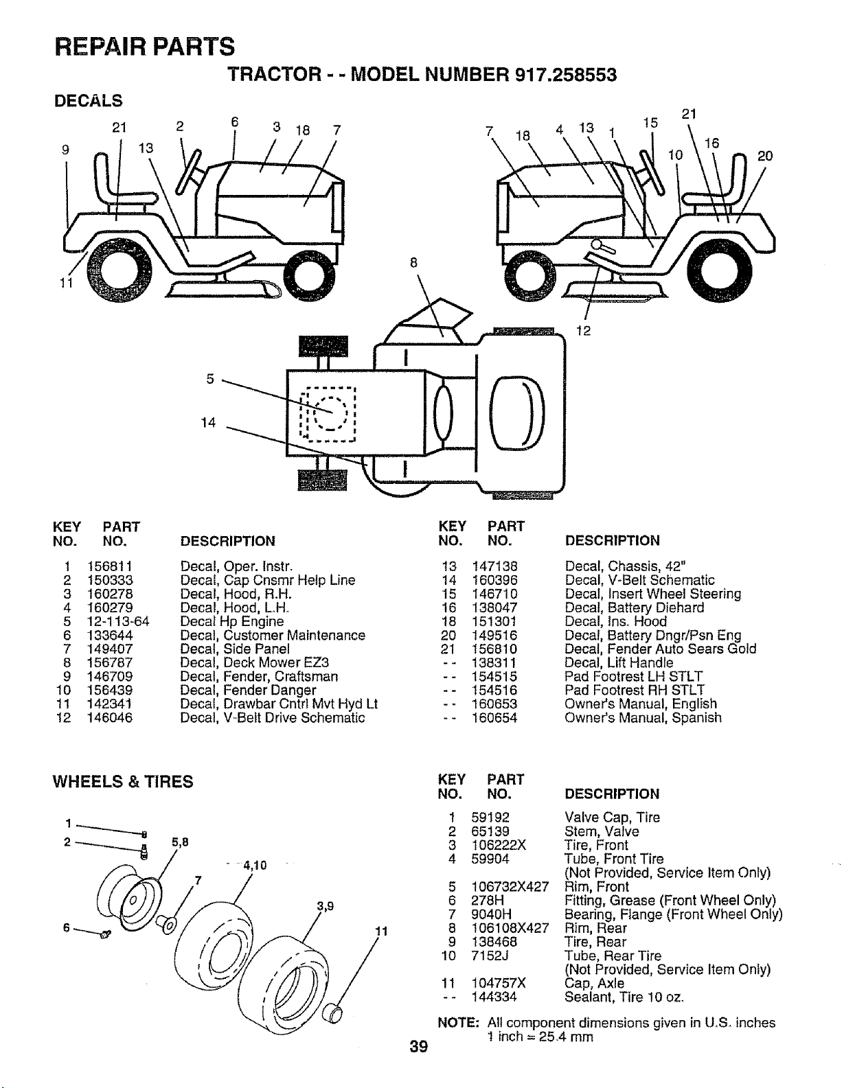
REPAIR PARTS
TRACTOR - - MODEL NUMBER 917.258553
DECALS
21 2 6 3 18 7 7 18 4 13 1
9 13
21
15
16
2O
11
8
\
5 0
_mlwlm!
÷=_, I
t t
I I
14 _ ',
12
KEY PART
NO. NO.
1 156811
2 15O333
3 160278
4 160279
5 12-113-64
6 133644
7 149407
8 156787
9 146709
10 156439
11 142341
12 146046
KEY PART
DESCRIPTION NO. NO.
Decal, Oper. Instr.
Decal, Cap Cnsmr Help Line
Decal, Hood, R.H.
Decal, Hood, LHo
Decal Hp Engine
Decal, Customer Maintenance
Decal, Side Panel
Decal, Deck Mower EZ3
Decal, Fender, Craftsman
Decal, Fender Danger
Decal, Drawbar Cntrl Mvt Hyd Lt
Decal, V_Belt Drive Schematic
13
t4
15
16
18
2O
21
=.
147138
160396
146710
138047
151301
149516
156810
138311
154515
154516
160653
160654
DESCRIPTION
Decal, Chassis, 42"
Decal, V-Belt Schematic
Decal, Insert Wheel Steering
Decal, Battery Diehard
Decal, ins° Hood
Decal, Battery Dngr/Psn Eng
Decal, Fender Auto Sears Gold
Decal, Lift Handle
Pad Footrest LH STLT
Pad Footrest RH STLT
Owner's Manual, English
Owner's Manual, Spanish
WHEELS & TIRES
2 _ 5,8
.... 4,10
7
11
KEY PART
NO. NO. DESCRIPTION
1 59192 Valve Cap, Tire
2 65139 Stem, Valve
3 106222X Tire, Front
4 59904 Tube, Front Tire
(Not Provided, Service Item Only)
5 106732X427 Rim, Front
6 278H Fitting, Grease (Front Wheel Only)
7 9040H Bearing, FIange (Front Wheel Only)
8 106108X427 Rim, Rear
9 138468 Tire, Rear
10 7152J Tube, Rear Tire
(Not Provided, Service Item Only)
11 104757X Cap, Axle
- - t44334 Sealant, Tire 10 oz.
NOTE: All component dimensions given in U,So inches
1 inch = 25.4 mm
39
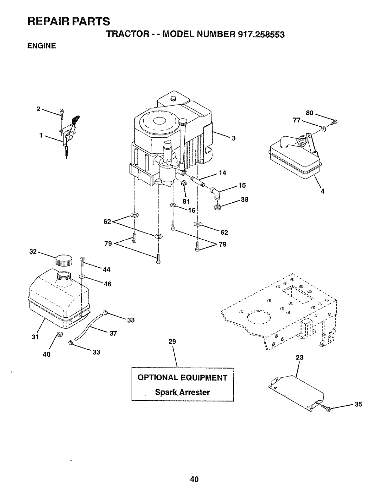
REPAIR PARTS
TRACTOR - - MODEL NUMBER 917.258553
ENGINE
!4
(
29
OPTIONAL EQUIPMENT
Spark Arrester
15
8O
4
23
35
4O
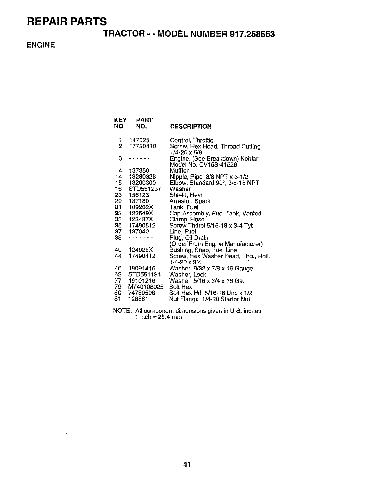
REPAIR PARTS
TRACTOR -- MODEL NUMBER 917.258553
ENGINE
KEY PART
NO. NO. DESCRIPTION
1
2
147025
17720410
4 137350
14 13280328
15 13200300
16 STD551237
23 156123
29 137180
31 109202X
32 123549X
33 123487X
35 17490512
37 137O4O
38 .......
40 124028X
44 17490412
46 19091416
62 STD551131
77 19101216
79 M740108025
80 74760508
81 128861
Control, Throttle
Screw, Hex Head, Thread Cutting
1/4-20 x 5/8
Engine, (See Breakdown) Kohler
Model Noo CV15S-41526
Muffler
Nipple, Pipe 3/8 NPT x 3-1/2
Elbow, Standard 90°, 3/8-18 NPT
Washer
Shield, Heat
Arrestor, Spark
Tank, Fuel
Cap Assembly, Fuel Tank, Vented
Clamp, Hose
Screw Thdrol 5/16-18 x 3-4 Tyt
Line, Fuel
Plug, Oil Drain
(Order From Engine Manufacturer)
Bushing, Snap, Fuel Line
Screw, Hex Washer Head, Thd.., Roll..
1/4-20 x 3/4
Washer 9/32 x 7/8 x 16 Gauge
Washer, Lock
Washer 5/16 x 3/4 x 16 Ga.
Bolt Hex
Bolt Hex Hd 5/16-'18 Unc x 1/2
Nut Flange 1/4-20 Starter Nut
NOTE: All component dimensions given in UoS. inches
1 inch = 25.4 mm
41
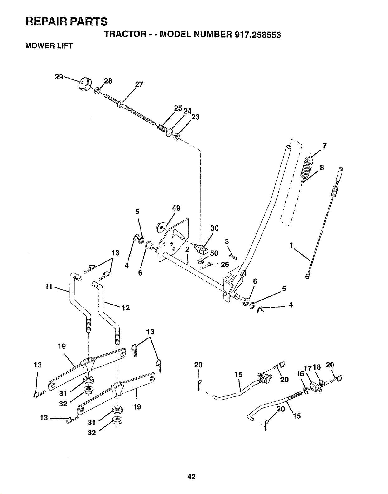
REPAIR PARTS
TRACTOR - - MODEL NUMBER 917.258553
MOWER LIFT
7
11
13
4
49
30
3
\
26
8
l I
I i
! I
! /
5
19
13
32
I
32
13
19
20
15
2O
15
42
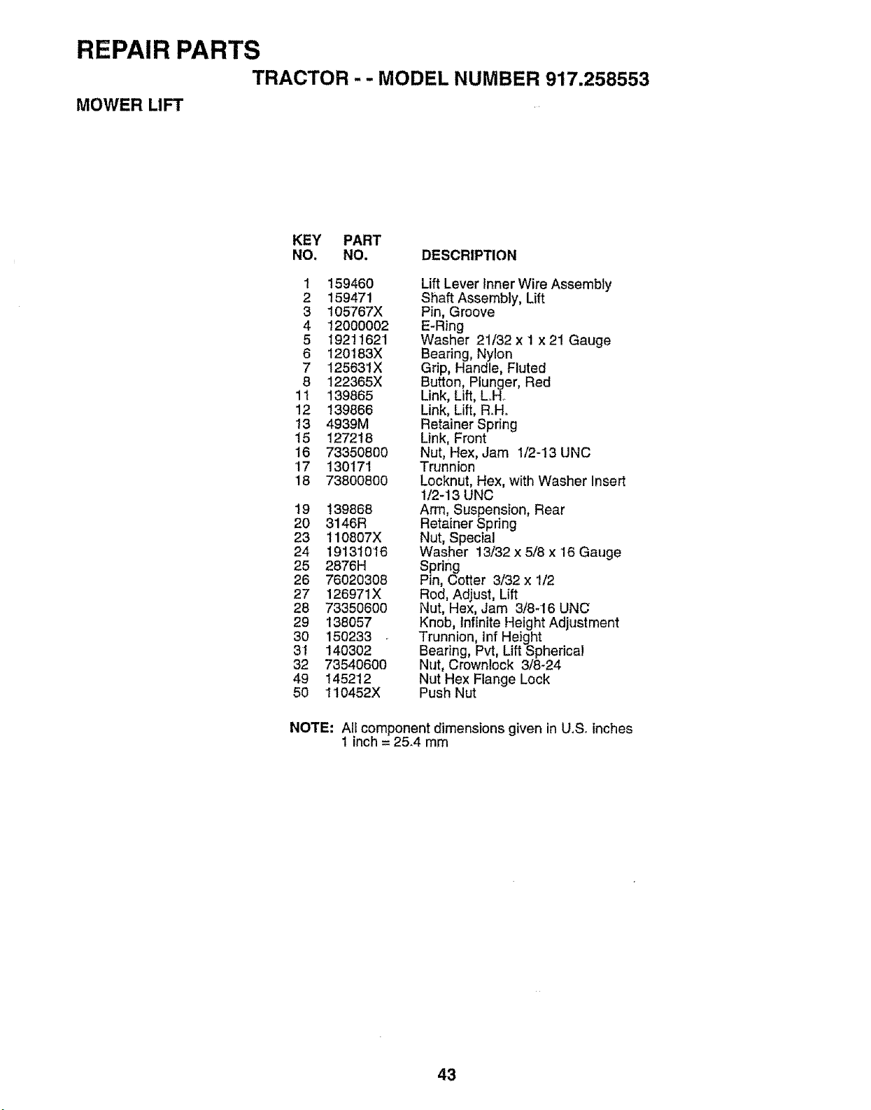
REPAIR PARTS
TRACTOR - - MODEL NUMBER 917.258553
MOWER LIFT
KEY PART
NO. NO, DESCRIPTION
1 159460
2 159471
3 105767X
4 12000002
5 19211621
6 120t83X
7 125631X
8 122365X
1t '139865
12 139866
13 4939M
15 127218
16 73350800
17 130171
18 73800800
19 139868
20 3146R
23 110807X
24 19131016
25 2876H
26 76020308
27 126971X
28 73350600
29 138057
30 150233
31 140302
32 73540600
49 145212
50 110452X
Lift Lever inner Wire Assembly
Shaft Assembly, Lift
Pin, Groove
E-Ring
Washer 21/32 x I x 21 Gauge
Bearing, Nylon
Grip, Handle, Fluted
Button, Plunger, Red
Link, Lift, Loll.
Link, Lift, R.H.
Retainer Spring
Link, Front
Nut, Hex, Jam 1/2-13 UNC
Trunnion
Locknut, Hex, with Washer Insert
1/2-13 UNC
Arm, Suspension, Rear
Retainer Spring
Nut, Special
Washer 13/32 x 5/8 x '16 Gauge
Spring
Pin, Cotter 3/32 x 1/2
Red, Adjust, Lift
Nut, Hex, Jam 3/8-16 UNC
Knob, infinite Height Adjustment
Trunnion, Inf Height
Bearing, Pvt, Lift Spherical
Nut, Crownlock 3/8_24
Nut Hex Flange Lock
Push Nut
NOTE" All component dimensions given in U,So inches
1 inch = 25.4 mm
43
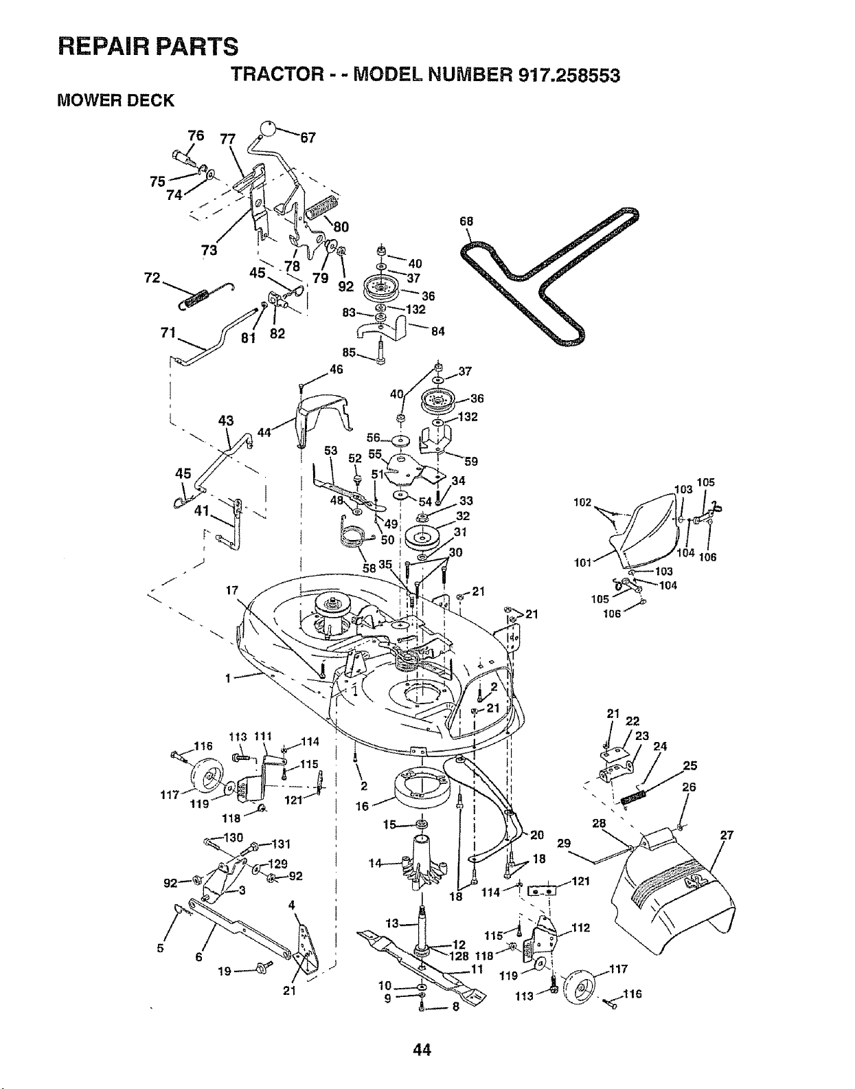
REPAIR PARTS
TRACTOR -- MODEL NUMBER 917o258553
MOWER DECK
76 77
113 111 114
1t6 -- _ i
11 i
118 _
1
6
21
22
24
\ 25
2 : 26
16
15.-_ 28 "
29
18
27
44
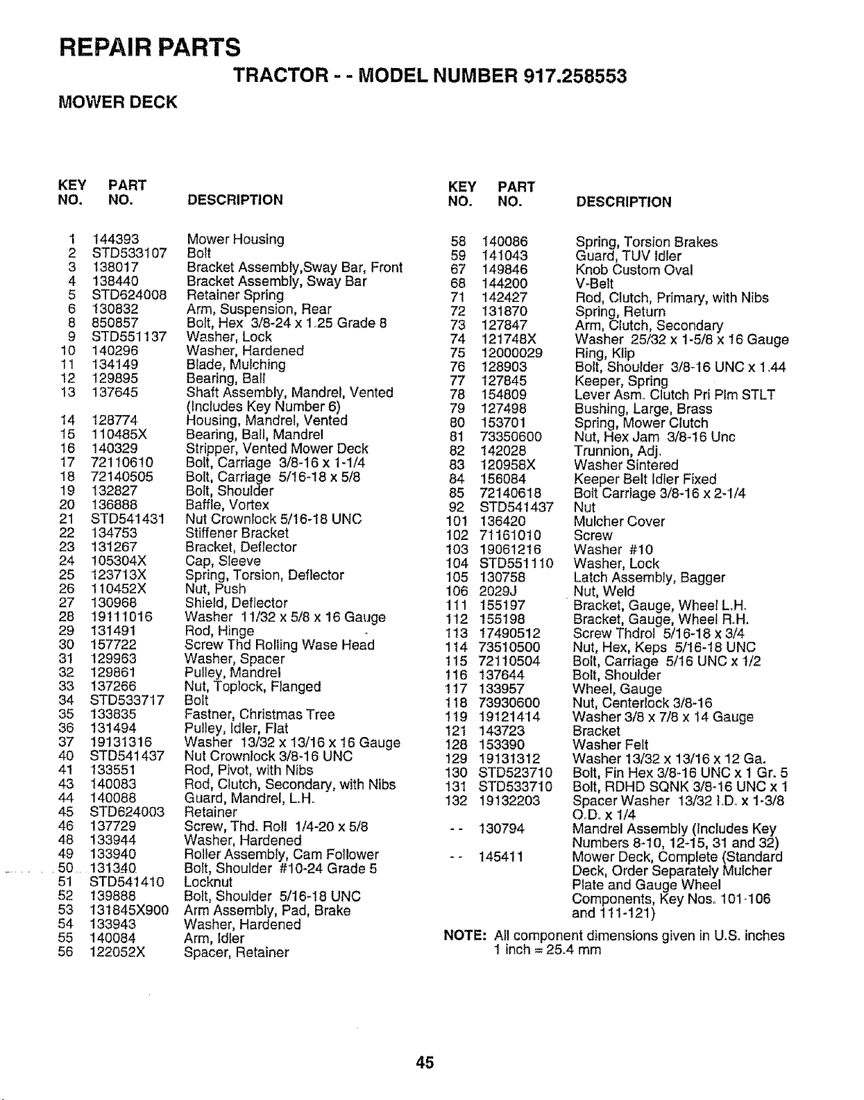
REPAIR PARTS
TRACTOR - - MODEL NUMBER 917.258553
MOWER DECK
KEY PART KEY PART
NO. NO. DESCRIPTION NO. NO. DESCRIPTION
1 144393 Mower Housing 58 140086
2 STD533107 Bolt 59 141043
3 138017 Bracket Assembly,Sway Bar, Front 67 149846
4 138440 Bracket Assembly, Sway Bar 68 144200
5 STD624008 Retainer Spring 7'1 142427
6 130832 Arm, Suspension, Rear 72 131870
8 850857 Bolt, Hex 3/8-24 x 125 Grade 8 73 127847
9 STD551137 Washer, Lock 74 121748X
10 140296 Washer, Hardened 75 !2000029
11 134149 Blade, Mulching 76 128903
12 129895 Bearing, Ball 77 127845
13 137645 Shaft Assembly, Mandrel, Vented 78 154809
(Includes Key Number 6) 79 127498
14 128774 Housing, Mandrel, Vented 80 153701
15 1'10485X Bearing, Ball, Mandrel 81 73350600
15 140329 Stripper, Vented Mower Deck 82 142028
17 72110610 Bolt, Carriage 3/8-16 x 1-1/4 83 120958X
18 72140505 Bolt, Carriage 5/16-18 x5/8 84 156084
19 132827 Bolt, Shoulder 85 72140618
20 136888 Baffle, Vortex 92 STD541437
21 STD541431 Nut Crownlock 5/t6-t8 UNC 101 136420
22 134753 Stiffener Bracket 102 7116't010
23 131267 Bracket, Deflector 103 19061216
24 105304X Cap, Sleeve 104 STD551110
25 123713X Spring, Torsion, Deflector 105 130758
26 110452X Nut, Push 106 2029J
27 130968 Shieid, Deflector 111 155197
28 19111016 Washer 11/32x5/Bx16Gauge 112 155198
29 131491 Rod, Hinge 113 17490512
30 157722 Screw Thd Rolling Wase Head 1t4 73510500
31 129953 Washer, Spacer t15 72110504
32 129861 Pulley, Mandre! 116 137644
33 137266 Nut, Toplock, FIanged 117 t33957
34 STD533717 Bolt 118 73930600
35 133835 Fastner, Christmas Tree 119 19121414
36 131494 Pulley, Idler, Flat 12t 143723
37 19131316 Washer 13/32 x 13/16 x 16 Gauge 128 153390
40 STD541437 Nut Crownlock3/8-16 UNC 129 19131312
41 133551 Rod, Pivot, with Nibs 130 STD523710
43 140083 Rod, Clutch, Secondary, with Nibs 131 STD533710
44 140088 Guard, Mandrel, L.H. 132 19132203
45 STD624003 Retainer
46 137729 Screw, Thd. Roll 1/4-20 x 5/8 - - 130794
48 133944 Washer, Hardened
49 133940 Roller Assembly, Cam Follower - - t454t 1
•50.. 1313_40. Bolt, Shoulder #10-24 Grade 5
51 STD541410 Locknut
52 139888 Bolt, Shoulder 5/16-18 UNC
53 131845X900 Arm Assembly, Pad, Brake
54 133943 Washer, Hardened
55 140084 Arm, Idler
56 122052X Spacer, Retainer
Spring, Torsion Brakes
Guard, TUV Idler
Knob Custom Oval
V-Belt
Rod, Clutch, Primary, with Nibs
Spring, Return
Arm, Clutch, Secondary
Washer 25/32 x 1-5/8 x 16 Gauge
Ring, Ktip
Bolt, Shoulder 3/8-16 UNC x 1.44
Keeper, Spring
Lever Asmo Clutch Pri Plm STLT
Bushing, Large, Brass
Spring, Mower Clutch
Nut, Hex Jam 3/8-16 Unc
Trunnion, Adj.
Washer Sintered
Keeper Belt Idler Fixed
Bolt Carriage 3/8-16 x 2-1/4
Nut
Mulcher Cover
Screw
Washer #10
Washer, Lock
Latch Assembly, Bagger
Nut, Weld
Bracket, Gauge, Wheel L.H.
Bracket, Gauge, Wheel Roll.
Screw Thdrol 5/16-18 x 3/4
Nut, Hex, Keps 5/16-18 UNC
Bolt, Carriage 5/16 UNC x 1/2
Bolt, Shoulder
Wheel, Gauge
Nut, Centerlock 3/8-16
Washer 3/8 x 7/8 x 14 Gauge
Bracket
Washer Felt
Washer 13/32 x 13/16 x 12 Ga.
Bolt, Fin Hex 3/8-16 UNC x 1 Gr. 5
Bolt, RDHD SQNK 3/8-16 UNC x 1
Spacer Washer 13/32 1.D_x 1-3/8
OoDox 1/4
Mandrel Assembly (Includes Key
Numbers 8-10, 12-15, 31 and 32)
Mower Deck, Complete (Standard
Deck, Order Separately Mulcher
Plate and Gauge Wheel
Components, Key Nos. 101-106
and 111-121)
NOTE: All component dimensions given in U.S. inches
1 inch = 25.4 mm
45
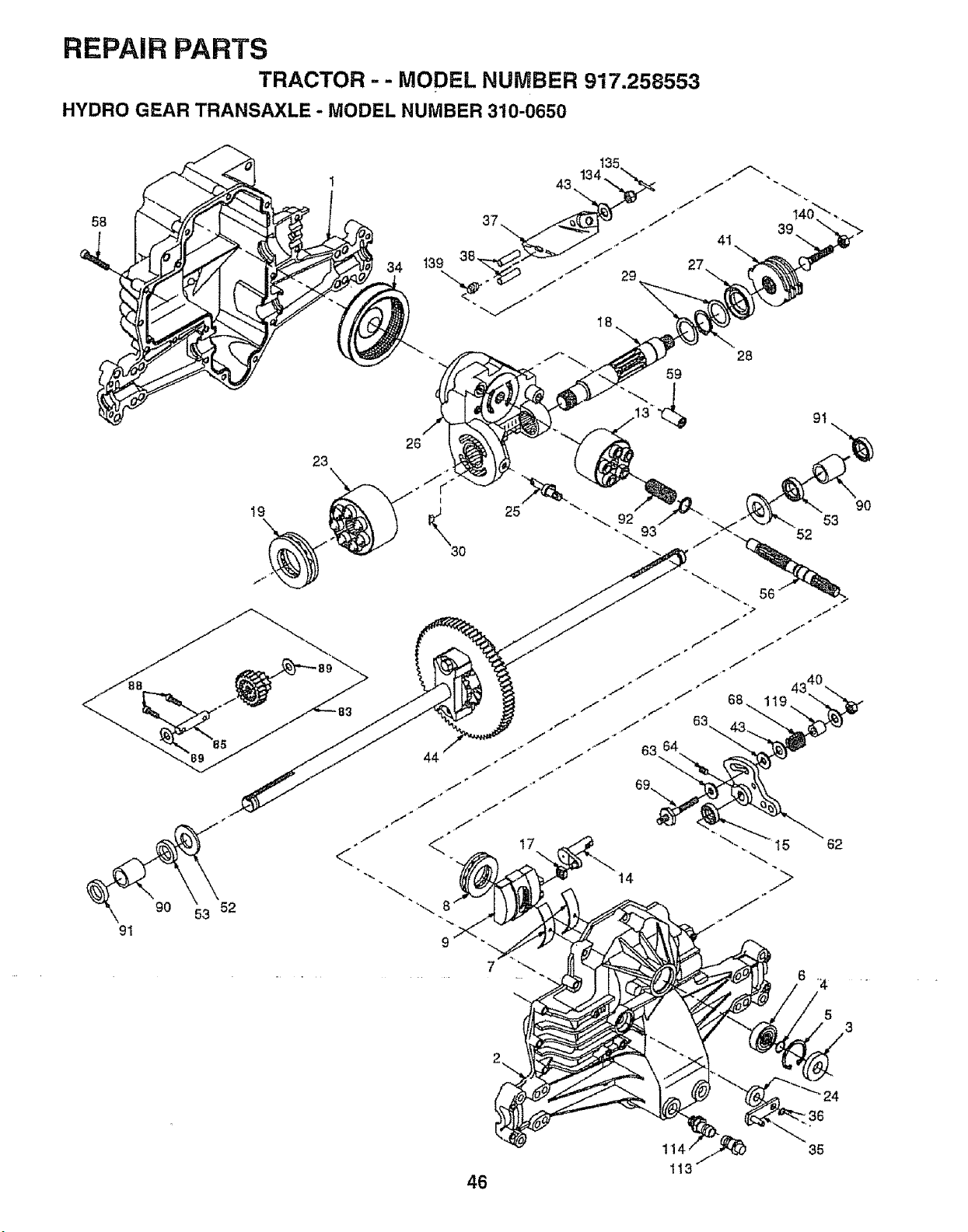
REPAIR PARTS
TRACTOR -- MODEL NUMBER 917.258553
HYDRO GEAR TRANSAXLE - MODEL NUMBER 310-0650
58
23
t9
9O 52
91
34
59
26
44
28
17
14
7
5
3
24
"36
35
1
113
46
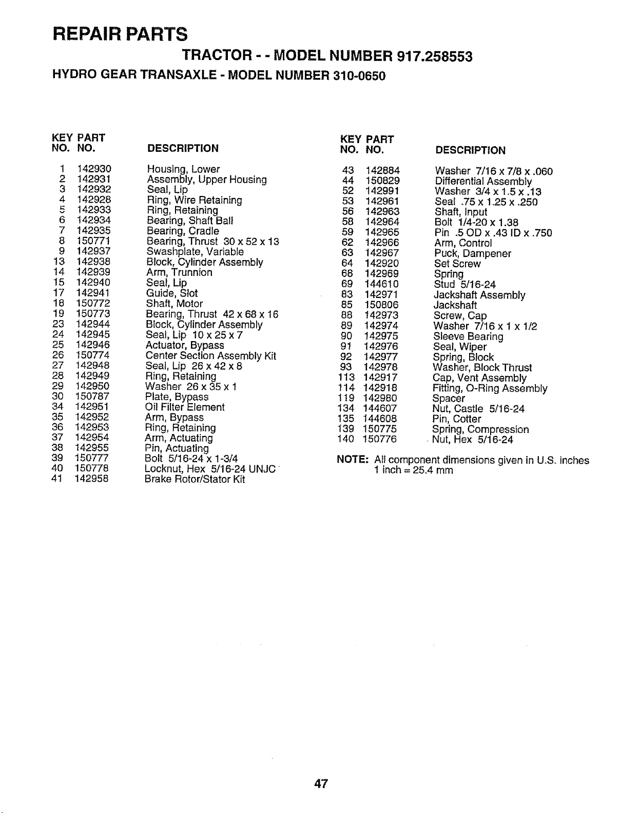
REPAIR PARTS
TRACTOR - - MODEL NUMBER 917.258553
HYDRO GEAR TRANSAXLE - MODEL NUMBER 310-0650
KEY PART KEY PART
NO. NO. DESCRIPTION NO. NO. DESCRIPTION
1 142930 Housing, Lower 43 142884
2 142931 Assembly, Upper Housing 44 150829
3 '142932 Seal, Lip 52 142991
4 !42928 Ring, Wire Retaining 53 142961
5 142933 Ring, Retaining 56 142963
6 142934 Bearing, Shaft Ball 58 142964
7 142935 Bearing, Cradle 59 142965
8 150771 Bearing, Thrust 30 x 52 x 13 62 142966
9 142937 Swashplate, Variable 63 142967
t3 142938 Block, Cylinder Assembly 64 142920
14 142939 Arm, Trunnion 68 142969
15 142940 Seal, Lip 69 144610
17 142941 Guide, Slot 83 142971
18 150772 Shaft, Motor 85 150806
19 150773 Bearing, Thrust 42 x68x 16 88 142973
23 142944 Block, Cylinder Assembly 89 142974
24 142945 Seal, Lip 10x25x7 90 142975
25 142946 Actuator, Bypass 91 142976
26 150774 Center Section Assembly Kit 92 142977
27 142948 Seal, Lip 26 x 42 x 8 93 142978
28 142949 Ring, Retaining 113 142917
29 142950 Washer 26x35x1 114 142918
30 150787 Plate, Bypass 1t9 142980
34 142951 Oil Filter Element 134 144607
35 142952 Arm, Bypass 135 144608
36 142953 Ring, Retaining 139 150775
37 142954 Arm, Actuating 140 150776
38 142955 Pin, Actuating
39 150777 Bolt 5/16-24 x 1-3/4
40 150778 Locknut, Hex 5/16-24 UNJC
41 142958 Brake Rotor/Stator Kit
Washer 7/16 x 7/8 x .060
Differential Assembly
Washer 3/4 x 1_5 x .t3
Seal .75 x 1.25 x .250
Shaft, Input
Bolt 1/4-20 x 1.38
Pin o50D x .43 ID x .750
Arm, Control
Puck, Dampener
Set Screw
Spring
Stud 5/16-24
Jackshaft Assembly
Jackshaft
Screw, Cap
Washer 7/16 x 1 x 1/2
Sleeve Bearing
Seal, Wiper
Spring, Block
Washer, Block Thrust
Cap, Vent Assembly
Fitting, O-Ring Assembly
Spacer
Nut, Castle 5/16-24
Pin, Cotter
Spring, Compression
Nut, Hex 5/16_24
NOTE: All component dimensions given in U.S. inches
1 inch = 25°4 mm
47
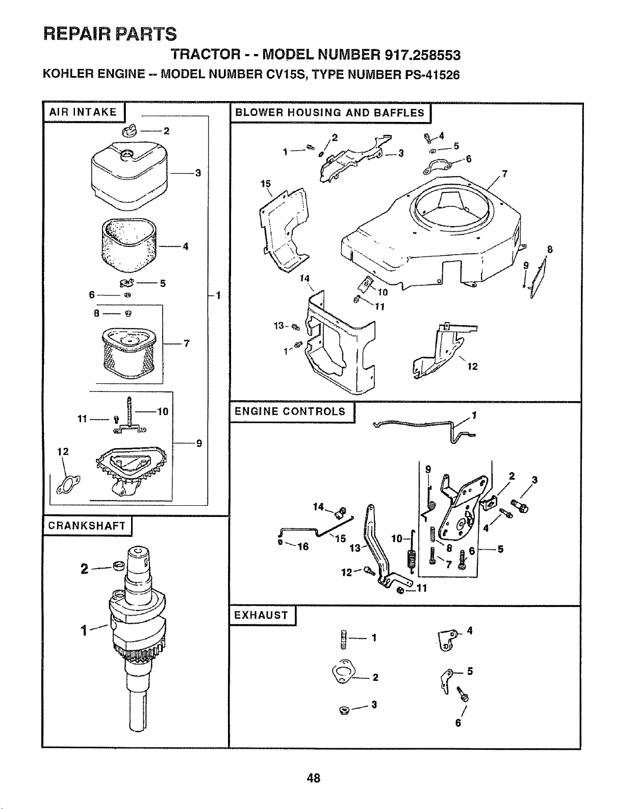
REPAIR PARTS
TRACTOR-- MODEL NUMBER 917.258553
KOHLER ENGINE -- MODEL NUMBER CV15S, TYPE NUMBER PS-41526
--3
6_
12
19
CRANKSHAFT I
H,IH,I I
-1
BLOWER HOUSING AND BAFFLES !
t5
\
14
13-% __
ENGINE CONTROLS I
........................................H HI
e_16
EXHAUST I
/
6
8
48
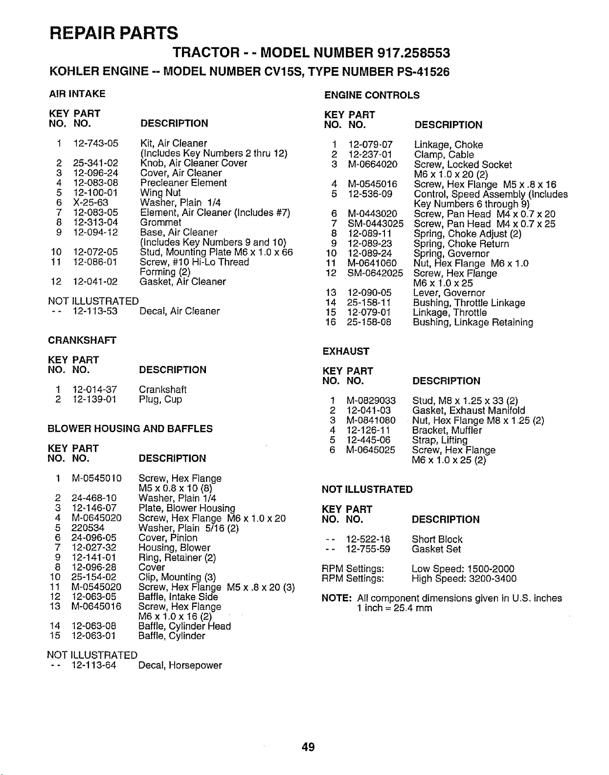
REPAIR PARTS
TRACTOR - - MODEL NUMBER 917.258553
KOHLER ENGINE -- MODEL NUMBER CV15S, TYPE NUMBER PS-41526
AIR INTAKE
ENGINE CONTROLS
KEY PART KEY PART
NO, NO. DESCRIPTION NO. NO. DESCRIPTION
2
3
4
5
6
7
8
9
12-743-05
25-341-02
12-096-24
12-083-08
12-100-01
X-25-63
12-083-05
12-313-04
12o094-t2
I0 12-072-05
11 12-086-01
12 12-041-02
Kit, Air Cleaner 1
(Includes Key Numbers 2 thru 12) 2
Knob, Air Cleaner Cover 3
Cover, Air Cleaner
Precleaner Element 4
Wing Nut 5
Washer, Plain 1/4
Element, Air Cleaner (Includes #7) 6
Grommet 7
Base, Air Cleaner 8
(Includes Key Numbers 9 and 10) 9
Stud, Mounting Plate M6 x 1.0 x 66 10
Screw, #10 Hi-Lo Thread 1t
Forming (2) 12
Gasket, Air Cleaner
NOT iLLUSTRATED
-- 12-113-53 Decal, Air Cleaner
CRANKSHAFT
KEY PART
NO. NO. DESCRIPTION
1 12_014-37 Crankshaft
2 t2-t39-01 Plug, Cup
BLOWER HOUSING AND BAFFLES
KEY PART
NO. NO. DESCRIPTION
M-0545010
2 24-468-10
3 12-t46_07
4 M-0645020
5 220534
6 24-096-05
7 12_027-32
9 12-141-01
8 12-096-28
10 25-154-02
11 M-0545020
12 12-063-05
13 M-0645016
14 12-063-08
15 12o063-01
Screw, Hex Flange
M5 x 0.8 x 10 (8)
Washer, Plain 1/4
Plate, Blower Housing
Screw, Hex Flange M6 x 1o0 x 20
Washer, Plain 5/!6 (2)
Cover, Pinion
Housing, Blower
Ring, Retainer (2)
Cover
Clip, Mounting (3)
Screw, Hex Flange M5 x .8 x 20 (3)
Baffle, Intake Side
Screw, Hex Flange
M6 x 1.0 x 16 (2)
Baffle, Cylinder Head
Baffle, Cylinder
12-079-07
12-237-01
M-0664020
M-0545016
12-536-09
M-0443020
SM-0443025
12-089-11
12-089-23
12-089-24
M-0641060
SM-0642025
13 12-090-05
14 25458-11
15 12_079-01
16 25-t58-08
Linkage, Choke
Clamp, Cable
Screw, Locked Socket
M6 x 1..0x 20 (2)
Screw, Hex Flange M5 x .8 x 16
Control, Speed Assembly (Includes
Key Numbers 6 through 9)
Screw, Pan Head M4 x 0°7 x 20
Screw, Pan Head M4 x &7 x 25
Spring, Choke Adjust (2)
Spring, Choke Return
Spring, Governor
Nut, Hex Flange M6 x 1.0
Screw, Hex Flange
M6 x 'I.0 x 25
Lever, Governor
Bushing, Throttle Linkage
Linkage, Throttle
Bushing, Linkage Retaining
EXHAUST
KEY PART
NO. NO.
1 M-0829033
2 12-041-03
3 M-0841080
4 12-126-11
5 12-445-06
6 M-0645025
DESCRIPTION
Stud, M8 x t.25 x 33 (2)
Gasket, Exhaust Manifold
Nut, Hex Flange M8 x 1.25 (2)
Bracket, Muffler
Strap, Lifting
Screw, Hex Flange
M6 x 1.0 x 25 (2)
NOT ILLUSTRATED
KEY PART
NO. NO, DESCRIPTION
- - 12-522-!8 Short Block
-- 12-755-59 Gasket Set
RPM Settings: Low Speed: 1500-2000
RPM Settings: High Speed: 3200-3400
NOTE: All component dimensions given in U,S, inches
1 inch = 25,4 mm
NOT ILLUSTRATED
-- 12-113-64 Decal, Horsepower
49
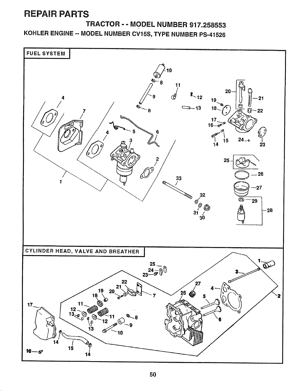
REPAIR PARTS
TRACTOR - - MODEL NUMBER 917.258553
KOHLER ENGINE -- MODEL NUMBER CV15S, TYPE NUMBER PS-41526
FUEL SYSTEM
llllllllllNl!lii i i
4
/
7
/
i,iiii ii i,ii, i i1,111
CYLINDER HEAD, VALVE AND BREATHER i
ii
19
18
22
21
20
25
14
/
15
13
14
12
tO
27
5
\
50
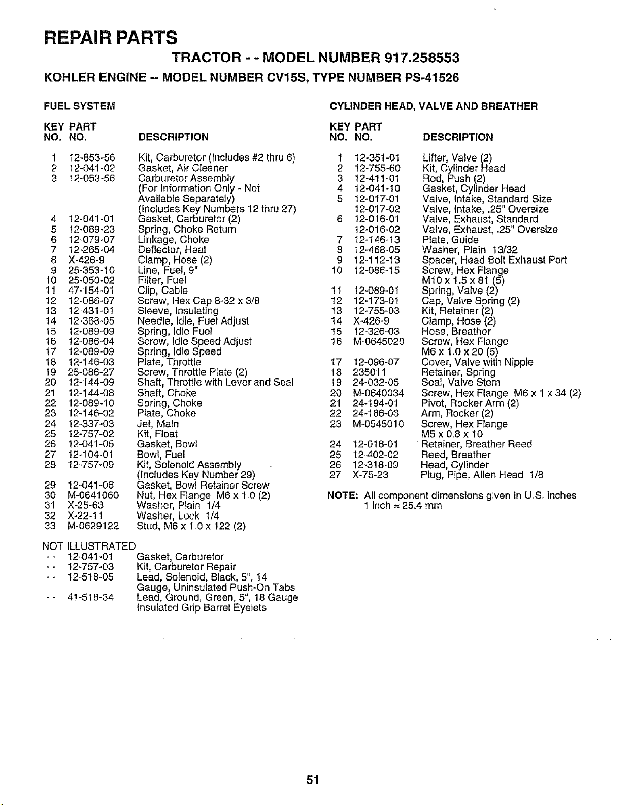
REPAIR PARTS
TRACTOR - - MODEL NUMBER 917.258553
KOHLER ENGINE -- MODEL NUMBER CV15S, TYPE NUMBER PS-41526
FUEL SYSTEM
CYLINDER HEAD, VALVE AND BREATHER
KEY PART KEY PART
NO. NO. DESCRIPTION NO. NO. DESCRIPTION
1 12-853-56
2 12-041-02
3 12-053-56
4 12-041-0!
5 12_089-23
6 t2_079-07
7 !2-265-04
8 X-426_9
9 25-353-10
t0 25-050-02
11 47-154-01
12 12-086-07
13 12_431-01
14 12-368-05
15 12-089-09
16 12-086-04
17 12-089-09
18 12-146-03
19 25-086-27
20 12-144-09
21 12-144-08
22 12-089_10
23 12-146-02
24 12-337_03
25 12_757-02
26 12-041-05
27 t2_104-01
28 12-757-09
Kit, Carburetor (Includes #2 thru 6)
Gasket, Air Cleaner
Carburetor Assembly
(For Information Only - Not
Available Separately)
(Includes Key Numbers 12 thru 27)
Gasket, Carburetor (2)
Spring, Choke Return
Linkage, Choke
Deflector, Heat
Clamp, Hose (2)
Line, Fuel, 9"
Filter, Fuel
Clip, Cable 11
Screw, Hex Cap 8-32 x 3/8 12
Sleeve, Insulating 13
Needle, Idle, Fuel Adjust 14
Spring, Idle Fuel 15
Screw, Idle Speed Adjust 16
Spring, Idle Speed
Plate, Throttle 17
Screw, Throttle Plate (2) 18
Shaft, Throttle with Lever and Seal 19
Shaft, Choke 20
Spring, Choke 21
Plate, Choke 22
Jet, Main 23
Kit, Float
Gasket, Bowl 24
Bowl, Fuel 25
Kit, Solenoid Assembly 26
(Includes Key Number 29) 27
Gasket, Bowl Retainer Screw
Nut, Hex Flange M6 x lrO (2)
Washer, Plain 1/4
Washer, Lock 1/4
Stud, M6 x 1o0x 122 (2)
29 12-041-06
30 M-0641060
31 X-25-63
32 X-22-11
33 M-0629122
NOT ILLUSTRATED
-- 12-041-01 Gasket, Carburetor
-- 12-757-03 Kit, Carburetor Repair
- - 12-518-05 Lead, Solenoid, Black, 5", 14
Gauge, Uninsulated Push-On Tabs
- - 41-518-34 Lead, Ground, Green, 5", 18 Gauge
Insulated Grip Barrel Eyelets
1 12-351-01
2 12-755-60
3 12_411-01
4 12-041-t0
5 t2-017-01
12-017-02
6 12-016-0!
12-0'16-02
7 12-146-13
8 12-468-05
9 12-112-13
10 12-086-15
12-089-01
12-173-01
12-755-03
X-426-9
12-326-03
M-0645020
12-096-07
235011
24-032-05
M-0640034
24-194-01
24_186_03
M-0545010
12-0tB-01
12-402-02
12_318-09
X-75_23
Lifter, Valve (2)
Kit, Cylinder Head
Rod, Push (2)
Gasket, Cylinder Head
Valve, Intake, Standard Size
Valve, Intake, .25" Oversize
Valve, Exhaust, Standard
Valve, Exhaust, .25" Oversize
Plate, Guide
Washer, Plain 13/32
Spacer, Head Bolt Exhaust Port
Screw, Hex Flange
M10 x 1o5 x 81 (5)
Spring, Valve (2)
Cap, Valve Spring (2)
Kit, Retainer (2)
Clamp, Hose (2)
Hose, Breather
Screw, Hex Flange
M6 x 1_0x 20 (5)
Cover, Valve with Nipple
Retainer, Spring
Seal, Valve Stem
Screw, Hex Flange M6 x 1 x 34 (2)
Pivot, Rocker Arm (2)
Arm, Rocker (2)
Screw, Hex Flange
M5x0o8x t0
Retainer, Breather Reed
Reed, Breather
Head, Cylinder
Plug, Pipe, Allen Head 1/8
NOTE: All component dimensions given in UoS_inches
1 inch = 25.4 mm
51
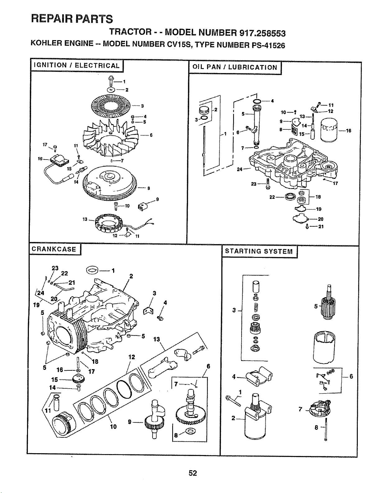
REPAIR PARTS
TRACTOR - - MODEL NUMBER 917,258553
KOHLER ENGINE -- MODEL NUMBER CV15S, TYPE NUMBER PS-41526
, i, i i,ii ,i ....
mN,TtON,'ELECTRICALl
13 __
CRANKCASE I
3
13
17
10
oi,_PAN.'I;uB_iCATIONI ....
J
J
r
0--4 _r_ 11
6.++.i_ 8--_ 15+ --16
24 +
C_--20
_--21
STARTING SYSTEM I
€:=
@
o
Q
1
_
52
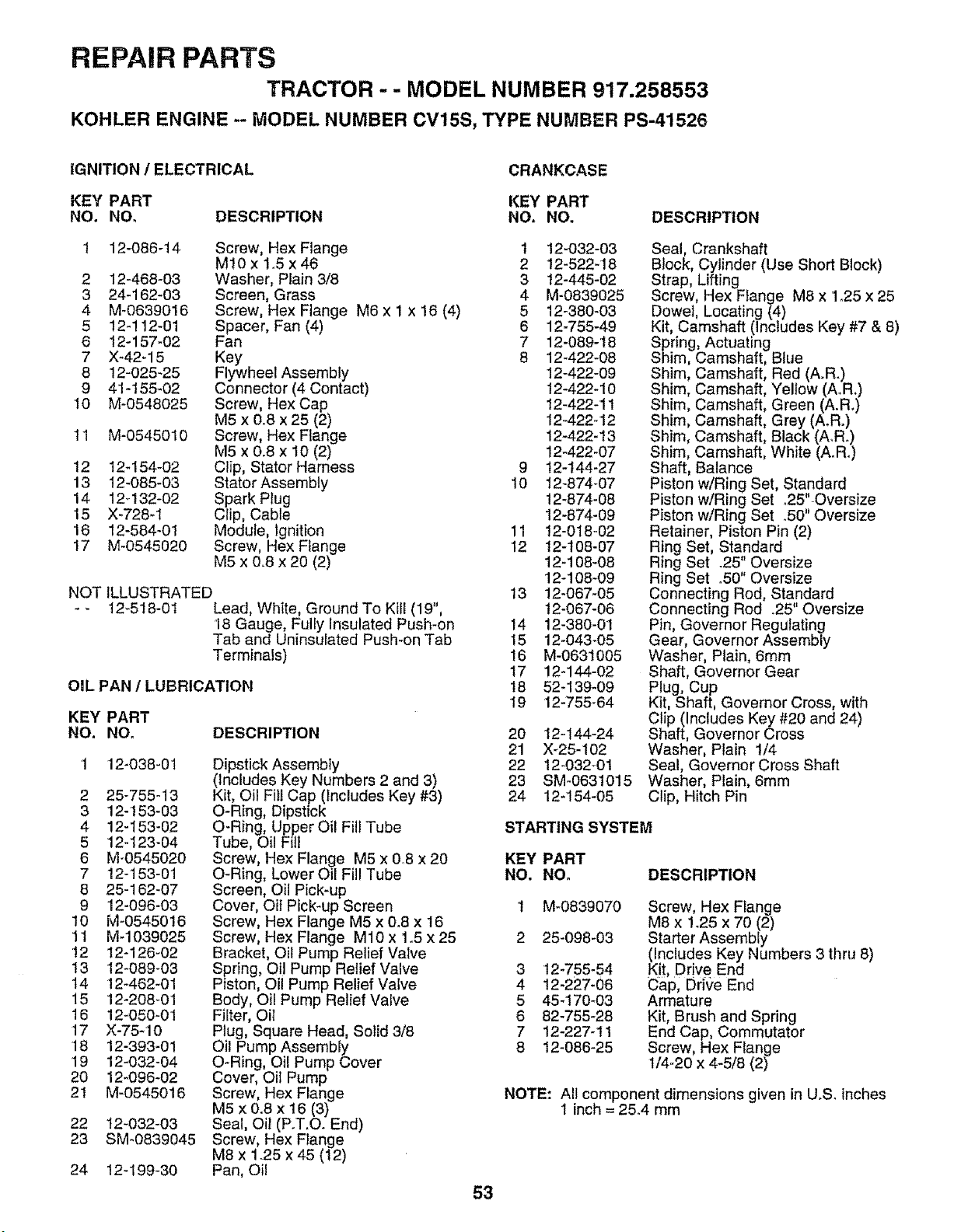
REPAIR PARTS
TRACTOR -- MODEL NUMBER 917.258553
KOHLER ENGINE -- MODEL NUMBER CV15S, TYPE NUMBER PS-41526
iGNITION / ELECTRICAL
CRANKCASE
KEY PART KEY PART
NO. NO. DESCRIPTION NO. NO. DESCRIPTION
1 12-086-14 Screw, Hex Flange t 12-032-03
MI0 x 1.5 x46 2 12-522-18
2 12-468-03 Washer, Plain 3/8 3 !2-445-02
3 24-162-03 Screen, Grass 4 M-0839025
4 M-0639016 Screw, Hex Flange M6 x 1 x !6 (4) 5 12-380-03
5 12-!12-01 Spacer, Fan (4) 6 12-755-49
6 12-157-02 Fan 7 12-089-18
7 X-42-15 Key 8 12-422-08
8 12-025-25 Flywheel Assembly 12-422-09
9 41-155_02 Connector (4 Contact) !2-422-10
10 M-0548025 Screw, Hex Cap 12-422-11
M5 x 0°8 x 25 (2) 12-422-12
11 M-0545010 Screw, Hex Flange 12-422-13
M5 x 0.8 x 10 (2) 12-422-07
12 t2-154-02 Clip, Stator Harness 9 t2-t44-27
13 12-085-03 Stator Assembly 10 12-874-07
14 12q32-02 Spark PIug 12-874-08
15 X-728-1 Clip, Cable 12-874-09
16 12-584-01 Module, Ignition 11 12-018-02
17 M-0545020 Screw, Hex Flange 12 12-108-07
M5 x 0.8 x 20 (2) 12-108-08
12-108-09
NOT ILLUSTRATED '13 12-067-05
-. 12_518-01 Lead, White, Ground To Kill (19", t2-067-06
18 Gauge, Fully Insulated Push-on 14 12-380-01
Tab and Uninsulated Push-on Tab 15 12-043-05
Terminals) 16 M-0631005
17 12-144-02
OIL PAN / LUBRICATION I8 52-139-09
19 12-755-64
KEY PART
NO. NO. DESCRIPTION
12-038-0t
2 25-755-13
3 12-153-03
4 12-153-02
5 12-123-04
6 Mo0545020
7 12-153-01
8 25-162-07
9 12-096-03
10 M-0545016
11 M-1039025
!2 12-126-02
13 12-069-03
t4 12-462-01
15 12-208-01
16 12-050-01
17 X-75-10
18 12-393-01
19 12-032-04
20 12-096-02
21 M-0545016
22 12-032-03
23 SM-0839045
Dipstick Assembly
(Includes Key Numbers 2 and 3)
Kit, Oil Fill Cap (includes Key #3)
O-Ring, Dipstick
O-Ring, Upper Oil Fill Tube
Tube, Oil Fill
Screw, Hex Flange M5 x 0,8 x 20
O-Ring, Lower Oil Fill Tube
Screen, Oil Pick-up
Cover, Oil Pick-up Screen
Screw, Hex Flange M5 x 0.8 x 16
Screw, Hex Flange M10 x 1°5 x 25
Bracket, Oil Pump Relief Valve
Spring, Oil Pump Relief Valve
Piston, Oil Pump Relief Valve
Body, Oil Pump Relief Valve
Filter, Oil
Plug, Square Head, Solid 3/8
Oil Pump Assembly
O-Ring, Oil Pump Cover
Cover, Oil Pump
Screw, Hex Flange
M5 x 0.8 x 16 (3)
Seal, Oil (P.T.O. End)
Screw, Hex Flange
M8 x 1.25 x 45 (!2)
Pan, Oil
53
24 12-199-30
20 12-144-24
21 X_25-102
22 12-032_01
23 SM-0631015
24 12-154-05
Seal, Crankshaft
Block, Cylinder (Use Short Block)
Strap, Lifting
Screw, Hex Flange M8 x 1,25 x 25
Dowel, Locating (4)
Kit, Camshaft (Includes Key #7 & 8)
Spring, Actuating
Shim Camshaft, Blue
Shim Camshaft, Red (A.R.)
Shim Camshaft, Yellow (A.R.)
Shim Camshaft, Green (A.R.)
Shim Camshaft, Grey (A.R.)
Shim Camshaft, Black (A.R.)
Shim Camshaft, White (A.Ro)
Shaft. Balance
Piston w/Ring Set, Standard
Piston wiRing Set 25".Oversize
Piston w/Ring Set °50" Oversize
Retainer, Piston Pin (2)
Ring Set, Standard
Ring Set 25" Oversize
Ring Set .50" Oversize
Connecting Rod, Standard
Connecting Rod .25' Oversize
Pin, Governor Regulating
Gear, Governor Assembly
Washer, Plain, 6ram
Shaft, Governor Gear
Plug, Cup
Kit, Shaft, Governor Cross, with
Clip (Includes Key #20 and 24)
Shaft, Governor Cross
Washer, Plain 1/4
Seal, Governor Cross Shaft
Washer, Plain, 6mm
Clip, Hitch Pin
STARTING SYSTEM
KEY PART
NO. NO. DESCRIPTION
M-0839070
25-098-03
3 t2-755-54
4 12-227-06
5 45-170-03
6 82-755-28
7 12-227-11
8 12-086-25
Screw, Hex Flange
M8 x 125 x 70 (2)
Starter Assembly
(includes Key Numbers 3 thru 8)
Kit, Dr!ve End
Cap, Drive End
Armature
Kit, Brush and Spring
End Cap, Commutator
Screw, Hex Flange
1/4-20 x 4-5/8 (2)
NOTE: All component dimensions given in U.S. inches
1 inch = 25.4 mm

,i,,,,11i,,,,,11,,,11,,i ,
RVICE
i1,_1111,1iiii i'1, i
54

SUGGESTED GUIDE FOR SaGHTtNG SLOPES FOR SAFE OPERATION
,-,,..,
SIGHTING
GUIDE
ONLY RIDE UP AND DOWN HILL,
NOT ACROSS HILL
SIGHT AND HOLD THIS LEVEL WITH
SKY LINE OR TREE.
15 ° MAX.

OWNER'S
MANUAL
MODEL NO.
917.258553
IF YOU NEED
REPAIR SERVICE
OR PARTS:
FOR REPAIR SERVICE, CALL
THIS TOLL FREE NUMBER:
1-800-4-REPAIR
(1-800-473-7247)
FOR REPLACEMENT PARTS
INFORMATION AND
ORDERING, CALL THIS
TOLL FREE NUMBER:
1-800-FON-PART
(1-800-366-7278)
=OR CONSUMER ASSISTANCE
HOT LINE, CALL THiS
TOLL FREE NUMBER:
1-800-659-5917
®
15.0 HP
ELECTRIC START
42" MOWER
AUTOMATIC (HYDROSTATIC)
LAWN TRACTOR
Each tractor has its own model number. Each engine has
its own model number.
The model number for your tractor well be found on the
model plate located under the seat.
The model number for your engine will be found on the
blower housing of the engine.
All parts listed herein may be ordered from any Sears,
Roebuck and Co. Service Center/Department and most Re-
tail Stores_
WHEN ORDERING REPAIR PARTS, ALWAYS GIVE THE
FOLLOWING INFORMATION:
= PRODUCT _TRACTOR
° MODEL NUMBER - 917.258553
', ENGINE MODEL NO.- 0V15, TYPE NO. PS-41526
= PART NUMBER
o PART DESCRIPTION
Your Sears merchandise has added value when you
consider Sears has service units nationwide staffed with
Sears trained technicians°_ professional technicians
specifically trained to insure that we meet our pledge to
you, we service what we see
" 160653 04o1597 KFSW
I'1''''_lI'1
IIIIIlllllllll IIIIIIIIIIIIIII
Printed in U:S,Ao


