User Manual
DIR-842V2
AC1200 Wi-Fi Gigabit Router
September 2020

DIR-842V2 AC1200 Wi-Fi Gigabit Router
User Manual
Page 2 of 200
Contents
Chapter 1. Introduction .................................................................................................... 5
Contents and Audience ..................................................................................................................................... 5
Conventions ............................................................................................................................................................ 5
Document Structure ............................................................................................................................................ 5
Chapter 2. Overview .............................................................................................................. 6
General Information ......................................................................................................................................... 6
Specifications ..................................................................................................................................................... 8
Product Appearance ..........................................................................................................................................13
Front Panel .....................................................................................................................................................13
Back Panel .......................................................................................................................................................15
Delivery Package...............................................................................................................................................17
Chapter 3. Installation and Connection .............................................................. 18
Before You Begin...............................................................................................................................................18
Connecting to PC...............................................................................................................................................19
PC with Ethernet Adapter ......................................................................................................................19
Obtaining IP Address Automatically (OS Windows 7) ...........................................................20
Obtaining IP Address Automatically (OS Windows 10) .........................................................25
PC with Wi-Fi Adapter .............................................................................................................................29
Obtaining IP Address Automatically
and Connecting to
Wireless Network (OS Windows 7) .....................................................................................................30
Obtaining IP Address Automatically and Connecting to
Wireless Network (OS Windows 10) ...................................................................................................33
Connecting to Web-based Interface ......................................................................................................36
Web-based Interface Structure ................................................................................................................38
Home Page .........................................................................................................................................................38
Internet Section .................................................................................................................................. 39
DIR-842V2 Section ................................................................................................................................ 40
Wi-Fi Clients Section ...................................................................................................................... 41
Menu Sections ................................................................................................................................................42
Notifications ................................................................................................................................................43
Chapter 4. Configuring via Web-based Interface .......................................... 44
Setup Wizard ........................................................................................................................................................44
Selecting Operation Mode ......................................................................................................................46
Router .......................................................................................................................................................... 46
Access Point or Repeater ............................................................................................................... 47
Changing LAN IPv4 Address ....................................................................................................................49
Wi-Fi Client ..................................................................................................................................................50
Configuring WAN Connection .................................................................................................................52
Static IPv4 Connection .................................................................................................................... 53
Static IPv6 Connection .................................................................................................................... 54
PPPoE, IPv6 PPPoE, PPPoE Dual Stack,
PPPoE + Dynamic IP (PPPoE Dual Access) Connections .................................................. 55
PPPoE + Static IP (PPPoE Dual Access) Connection ....................................................... 56

DIR-842V2 AC1200 Wi-Fi Gigabit Router
User Manual
Page 3 of 200
PPTP + Dynamic IP or L2TP + Dynamic IP Connection .................................................... 57
PPTP + Static IP or L2TP + Static IP Connection ......................................................... 58
Configuring Wireless Network .............................................................................................................59
Configuring LAN Ports for IPTV/VoIP ............................................................................................61
Changing Web-based Interface Password .......................................................................................63
Settings / Internet .......................................................................................................................................65
WAN ........................................................................................................................................................................65
Creating Dynamic IPv4 or Static IPv4 WAN Connection ............................................... 67
Creating Dynamic IPv6 or Static IPv6 WAN Connection ............................................... 70
Creating PPPoE WAN Connection ................................................................................................... 73
Creating PPTP, L2TP, or L2TP over IPsec WAN Connection ........................................ 78
Creating PPPoE IPv6 or PPPoE Dual Stack WAN Connection ........................................ 83
VLAN .....................................................................................................................................................................89
DNS ........................................................................................................................................................................92
Settings / WAN Failover ..............................................................................................................................94
Settings / Wireless network ....................................................................................................................96
Settings / Network....................................................................................................................................... 104
IPv4 ............................................................................................................................................................. 104
IPv6 ............................................................................................................................................................. 110
Functions / Firewall .................................................................................................................................. 114
IP Filter ...................................................................................................................................................... 114
DMZ ..................................................................................................................................................................... 118
MAC Filter .................................................................................................................................................... 119
AdBlock ........................................................................................................................................................... 121
Functions / Wi-Fi ......................................................................................................................................... 122
Client Management ................................................................................................................................... 122
WPS ..................................................................................................................................................................... 123
Using WPS Function via Web-based Interface .................................................................. 125
Using WPS Function without Web-based Interface ......................................................... 125
WMM ..................................................................................................................................................................... 126
Client ............................................................................................................................................................. 128
Client Shaping .......................................................................................................................................... 130
Additional .................................................................................................................................................... 132
MAC Filter .................................................................................................................................................... 136
Roaming ........................................................................................................................................................... 138
Functions / Advanced ................................................................................................................................
.. 140
UPnP IGD ......................................................................................................................................................... 140
Remote Access ............................................................................................................................................. 141
Virtual Servers ........................................................................................................................................ 143
TR-069 Client ............................................................................................................................................. 146
Static Route ............................................................................................................................................... 148
Dynamic DNS .................................................................................................................................................. 150
IPsec ................................................................................................................................................................ 152
Ports Settings .......................................................................................................................................... 159
Redirect ......................................................................................................................................................... 162
IGMP/MLD ......................................................................................................................................................... 163

DIR-842V2 AC1200 Wi-Fi Gigabit Router
User Manual
Page 4 of 200
ALG/Passthrough ........................................................................................................................................ 164
Management.......................................................................................................................................................... 166
System Time .................................................................................................................................................. 166
System Log .................................................................................................................................................... 168
Administration .......................................................................................................................................... 171
Telnet/SSH .................................................................................................................................................... 173
Yandex.DNS .................................................................................................................................................... 174
Settings ................................................................................................................................................... 174
Devices and Rules .............................................................................................................................. 176
Firmware Update ........................................................................................................................................ 178
Local Update .......................................................................................................................................... 179
Remote Update ....................................................................................................................................... 180
Schedule ......................................................................................................................................................... 181
Statistics .................................................................................................................................................... 185
Network Statistics ........................................................................................................................... 185
Port Statistics .................................................................................................................................. 186
Routing ..................................................................................................................................................... 187
DHCP ............................................................................................................................................................. 189
Multicast Groups ................................................................................................................................ 190
Diagnostics .................................................................................................................................................. 191
Ping ............................................................................................................................................................. 191
Traceroute .............................................................................................................................................. 193
Chapter 5. Operation Guidelines ............................................................................ 195
Safety Rules and Conditions ................................................................................................................. 195
Wireless Installation Considerations ............................................................................................ 196
Chapter 6. Abbreviations and Acronyms.............................................................. 197
DIR-842V2 AC1200 Wi-Fi Gigabit Router
Page 5 of 200
User Manual
Introduction
CHAPTER 1. INTRODUCTION
Contents and Audience
This manual describes the router DIR-842V2 and explains how to configure and operate it.
Conventions
Example Description
text The body text of the manual.
Before You Begin A reference to a chapter or section of this manual.
“Quick Installation
Guide”
A reference to a document.
Change
A name of a menu, menu item, control (field, checkbox, drop-down
list, button, etc.).
192.168.0.1
Data that you should enter in the specified field.
!
Information
An important note.
Document Structure
Chapter 1 describes the purpose and structure of the document.
Chapter 2 gives an overview of the router's hardware and software features, describes its
appearance and the package contents.
Chapter 3 explains how to install the router DIR-842V2 and configure a PC in order to access its
web- based interface.
Chapter 4 describes all pages of the web-based interface in detail.
Chapter 5 includes safety instructions and tips for networking.
Chapter 6 introduces abbreviations and acronyms most commonly used in User Manuals for D-
Link customer premises equipment.

DIR-842V2 AC1200 Wi-Fi Gigabit Router
User Manual
Overview
Page 6 of 200
CHAPTER 2. OVERVIEW
General Information
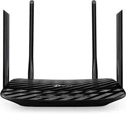
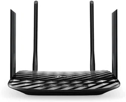
The DIR-842V2 device is a wireless dual band gigabit router with a built-in 4-port switch. It provides
a fast and simple way to create a wireless and wired network at home or in an office..
Also you are able to connect the wireless router DIR-842V2 to a cable or DSL modem or to a private
Ethernet line and use a high-speed Internet connection to successfully fulfill a wide range of
professional tasks. The built-in 4-port switch enables you to connect Ethernet-enabled computers,
game consoles, and other devices to your network.
Using the DIR-842V2 device, you are able to quickly create a high-speed wireless network at home
or in your office, which lets computers and mobile devices access the Internet virtually anywhere
(within the operational range of your wireless network). Simultaneous activity of 2.4GHz band and
5GHz band allows performing a wide range of tasks. The router can operate as a base station for
connecting wireless devices of the standards 802.11a, 802.11b, 802.11g, 802.11n, and 802.11ac (at
the wireless connection rate up to 1166Mbps1).
The router supports multiple functions for the wireless interface: several security standards (WEP,
WPA/WPA2/WPA3), MAC address filtering, WPS, WMM.
In addition, the device is equipped with a button for switching the Wi-Fi network off/on. If needed,
for example, when you leave home, you can easily switch the router’s WLAN by pressing the button,
and devices connected to the LAN ports of the router will stay online.
Multi-user MIMO technology allows to distribute the router's resources to let multiple wireless clients
use the Wi-Fi network efficiently, keeping high rates for HD media streaming, lag-free gaming, and
fast transfer of large files.
Transmit Beamforming technology allows to flexibly change the antennas' radiation pattern and to
redistribute the signal directly to wireless devices connected to the router.
Smart adjustment of Wi-Fi clients is useful for networks based on several D-Link access points or
routers – when the smart adjustment function is configured on each of them, a client always connects
to the access point (router) with the highest signal level.
Support of guest Wi-Fi network allows you to create a separate wireless network with individual
security settings and maximum rate limitation. Devices connected to the guest network will be able
to access the Internet, but will be isolated from the devices and resources of the router's LAN.
The wireless router DIR-842V2 includes a built-in firewall. The advanced security functions
minimize threats of hacker attacks, and prevent unwanted intrusions to your network.
The SSH protocol support provides more secure remote configuration and management of the
router due to encryption of all transmitted traffic, including passwords.
In addition, the router supports IPsec and allows to create secure VPN tunnels. Support of the IKEv2
protocol allows to provide simplified message exchange and use asymmetric authentication engine

DIR-842V2 AC1200 Wi-Fi Gigabit Router
User Manual
Overview
Page 7 of 200
upon configuration of an IPsec tunnel.
Built-in Yandex.DNS service protects against malicious and fraudulent web sites and helps to block
access to adult content on children's devices.
1 Up to 300Mbps for 2.4GHz and up to 866Mbps for 5GHz.

DIR-842V2 AC1200 Wi-Fi Gigabit Router
User Manual
Overview
Page 8 of 200
Now the schedules are also implemented; they can be applied to the rules of various filters and used
to reboot the router at the specified time or every specified time period and to enable/disable the
wireless network.
You can configure the settings of the wireless router DIR-842V2 via the user-friendly web-based
interface (the interface is available in several languages).
The Setup Wizard allows you to quickly switch DIR-842V2 to one of the following modes: router
(for connection to a wired or wireless ISP), access point, repeater, or client, and then configure all
needed setting for operation in the selected mode in several simple steps.
Also DIR-842V2 supports configuration and management via mobile application for Android and
iPhone smartphones.
You can simply update the firmware: the router itself finds approved firmware on D-Link update
server and notifies when ready to install it.

DIR-842V2 AC1200 Wi-Fi Gigabit Router
User Manual
Overview
Page 9 of 200
Specifications*
Hardware
Processor
· RTL8197FH-VG (1GHz)
RAM
· 128MB, DDR2, built in processor
Flash
· 128MB, SPI NAND
Interfaces
·
10/100/1000BASE-T WAN port
·
4 10/100/1000BASE-T LAN ports
LEDs
·
Power
·
Internet
·
WLAN 2.4G
·
WLAN 5G
Buttons
·
ON/OFF button to power on/power off
·
RESET button to restore factory default settings
·
WPS button to set up wireless connection and enable/disable wireless network
Antenna
· Four external non-detachable antennas (5dBi gain)
MIMO
· 2 x 2, MU-MIMO
Power connector
· Power input connector (DC)
Software
WAN connection types
·
PPPoE
·
IPv6 PPPoE
·
PPPoE Dual Stack
·
Static IPv4 / Dynamic IPv4
·
Static IPv6 / Dynamic IPv6
·
PPPoE + Static IP (PPPoE Dual Access)
·
PPPoE + Dynamic IP (PPPoE Dual Access)
·
PPTP/L2TP + Static IP
·
PPTP/L2TP + Dynamic IP
Network functions
·
DHCP server/relay
·
Advanced configuration of built-in DHCP server
·
Stateful/Stateless mode for IPv6 address assignment, IPv6 prefix delegation
·
Automatic obtainment of LAN IP address (for access point/repeater/client
modes)
·
DNS relay
·
Dynamic DNS
·
Static IPv4/IPv6 routing
·
IGMP/MLD Proxy
·
RIP
·
Support of UPnP IGD
·
Support of VLAN
·
WAN ping respond
·
Support of SIP ALG
·
Support of RTSP
·
WAN failover
·
Autonegotiation of speed, duplex mode, and flow control / Manual speed and
duplex mode setup for each Ethernet port


DIR-842V2 AC1200 Wi-Fi Gigabit Router
User Manual
Overview
Page 11 of
Software
Firewall functions
·
Network Address Translation (NAT)
·
Stateful Packet Inspection (SPI)
·
IPv4/IPv6 filter
·
MAC filter
·
Ad blocking function2
·
DMZ
·
Virtual servers
·
Built-in Yandex.DNS web content filtering service
VPN
·
IPsec/PPTP/L2TP/PPPoE pass-through
·
PPTP/L2TP tunnels
·
L2TP over IPsec
·
IPsec tunnels
Transport/Tunnel mode
IKEv1/IKEv2 support
DES encryption
NAT Traversal
Support of DPD (Keep-alive for VPN tunnels)
Management and monitoring
·
Local and remote access to settings through SSH/TELNET/WEB
(HTTP/HTTPS)
·
Multilingual web-based interface for configuration and management
·
Support of D-Link Assistant application for Android and iPhone smartphones
·
Notification on connection problems and auto redirect to settings
·
Firmware update via web-based interface
·
Automatic notification on new firmware version
·
Saving/restoring configuration to/from file
·
Support of logging to remote host
·
Automatic synchronization of system time with NTP server and manual
time/date setup
·
Ping utility
·
Traceroute utility
·
TR-069 client
·
Schedules for filters rules, automatic reboot, and enabling/disabling wireless
network
Wireless Module Parameters
Standards
· IEEE 802.11a/n/ac
· IEEE 802.11b/g/n
·
IEEE 802.11k
Frequency range
The frequency range depends upon the
radio frequency regulations applied in your
country
· 2400 ~ 2483.5MHz
· 5150 ~ 5350MHz
· 5650 ~ 5850MHz
Wireless connection security
·
WEP
·
WPA/WPA2 (Personal/Enterprise)
·
WPA3 (Personal)
·
МАС filter
·
WPS (PBC)
Advanced functions
·
Support of client mode
·
WMM (Wi-Fi QoS)
·
Information on connected Wi-Fi clients
·
Advanced settings

DIR-842V2 AC1200 Wi-Fi Gigabit Router
User Manual
Overview
Page 12 of
2 Will be available in future software versions.

DIR-842V2 AC1200 Wi-Fi Gigabit Router
User Manual
Overview
Page 13 of 200
Wireless Module Parameters
·
Smart adjustment of Wi-Fi clients
·
Guest Wi-Fi / support of MBSSID
·
Rate limitation for wireless network/separate MAC addresses
·
Periodic scan of channels, automatic switch to least loaded channel
·
Support of 802.11ac (5GHz) and 802.11n (2.4GHz) TX Beamforming
·
Autonegotiation of channel bandwidth in accordance with environment
conditions (20/40 Coexistence)
·
Support of STBC
Wireless connection rate
· IEEE 802.11a: 6, 9, 12, 18, 24, 36, 48, and 54Mbps
· IEEE 802.11b: 1, 2, 5.5, and 11Mbps
· IEEE 802.11g: 6, 9, 12, 18, 24, 36, 48, and 54Mbps
·
IEEE 802.11n (2.4GHz): from 6.5 to 300Mbps (MCS0–MCS15)
·
IEEE 802.11n (5GHz): from 6.5 to 300Mbps (from MCS0 to MCS15)
·
IEEE 802.11ac (5GHz): from 6.5 to 866Mbps
Transmitter output power
The maximum value of the transmitter
output power depends upon the radio
frequency regulations applied in your
country
·
802.11a (typical at room temperature 25 °C)
15dBm at 6, 54Mbps
·
802.11g (typical at room temperature 25 °C)
15dBm at 6, 54Mbps
·
802.11n (typical at room temperature 25 °C)
2.4GHz
15dBm at MCS0, 7
5GHz
15dBm at MCS0, 7
·
802.11ac (typical at room temperature 25 °C)
15dBm at MCS0, 9
Receiver sensitivity
·
802.11a (typical at PER < 10% (1000-byte PDUs) at room temperature 25 °C)
-95dBm at 6Mbps
-93dBm at 9Mbps
-92dBm at 12Mbps
-90dBm at 18Mbps
-87dBm at 24Mbps
-84dBm at 36Mbps
-80dBm at 48Mbps
-78dBm at 54Mbps
·
802.11b (typical at PER = 8% (1000-byte PDUs) at room temperature 25 °C)
-90dBm at 1Mbps
-92dBm at 2Mbps
-93dBm at 5.5Mbps
-96dBm at 11Mbps
·
802.11g (typical at PER < 10% (1000-byte PDUs) at room temperature 25 °C)
-94dBm at 6Mbps
-92dBm at 9Mbps
-90dBm at 12Mbps
-89dBm at 18Mbps
-87dBm at 24Mbps
-84dBm at 36Mbps
-80dBm at 48Mbps
-77dBm at 54Mbps

DIR-842V2 AC1200 Wi-Fi Gigabit Router
User Manual
Overview
Page 14 of 200
Wireless Module Parameters
·
802.11n (typical at PER = 10% (1000-byte PDUs) at room temperature 25 °C)
2.4GHz, HT20
-95dBm at MCS0
-91dBm at MCS1
-88dBm at MCS2
-86dBm at MCS3
-82dBm at MCS4
-79dBm at MCS5
-77dBm at MCS6
-75dBm at MCS7
2.4GHz, HT40
-92dBm at MCS0
-89dBm at MCS1
-86dBm at MCS2
-83dBm at MCS3
-80dBm at MCS4
-77dBm at MCS5
-74dBm at MCS6
-72dBm at MCS7
5GHz, HT20
-95dBm at MCS0
-93dBm at MCS1
-90dBm at MCS2
-87dBm at MCS3
-83dBm at MCS4
-79dBm at MCS5
-77dBm at MCS6
-75dBm at MCS7
5GHz, HT40
-92dBm at MCS0
-89dBm at MCS1
-86dBm at MCS2
-83dBm at MCS3
-80dBm at MCS4
-76dBm at MCS5
-74dBm at MCS6
-72dBm at MCS7
·
802.11ac (typical at PER = 10% (1000-byte PDUs) at room temperature 25 °C)
VHT20
-95dBm at MCS0
-92dBm at MCS1
-90dBm at MCS2
-86dBm at MCS3
-83dBm at MCS4
-79dBm at MCS5
-77dBm at MCS6
-75dBm at MCS7
-71dBm at MCS8
VHT40
-92dBm at MCS0
-89dBm at MCS1
-87dBm at MCS2
-84dBm at MCS3
-80dBm at MCS4
-76dBm at MCS5
-74dBm at MCS6
-72dBm at MCS7
-68dBm at MCS8
-66dBm at MCS9
DIR-842V2 AC1200 Wi-Fi Gigabit Router
User Manual
Overview
Page 15 of 200
Wireless Module Parameters
VHT80
-89dBm at MCS0
-86dBm at MCS1
-83dBm at MCS2
-80dBm at MCS3
-77dBm at MCS4
-73dBm at MCS5
-71dBm at MCS6
-69dBm at MCS7
-66dBm at MCS8
-64dBm at MCS9
Modulation schemes
·
802.11a: BPSK, QPSK, 16QAM, 64QAM with OFDM
·
802.11b: DQPSK, DBPSK, DSSS, CCK
·
802.11g: BPSK, QPSK, 16QAM, 64QAM with OFDM
·
802.11n: BPSK, QPSK, 16QAM, 64QAM with OFDM
·
802.11ac: BPSK, QPSK, 16QAM, 64QAM, up to 256QAM with OFDM
Physical Parameters
Dimensions (L x W x H)
· 181 x 132.5 x 47.71 mm (7.13 x 5.22 x 1.88 in)
Weight
· 304.8 g (0.67 lb)
Operating Environment
Power
· Output: 12V DC, 1A
Temperature
·
Operating: from 0 to 40 °C
·
Storage: from -20 to 65 °C
Humidity
·
Operating: from 10% to 90% (non-condensing)
·
Storage: from 5% to 95% (non-condensing)
DIR-842V2 AC1200 Wi-Fi Gigabit Router
User Manual
Overview
Page 16 of 200
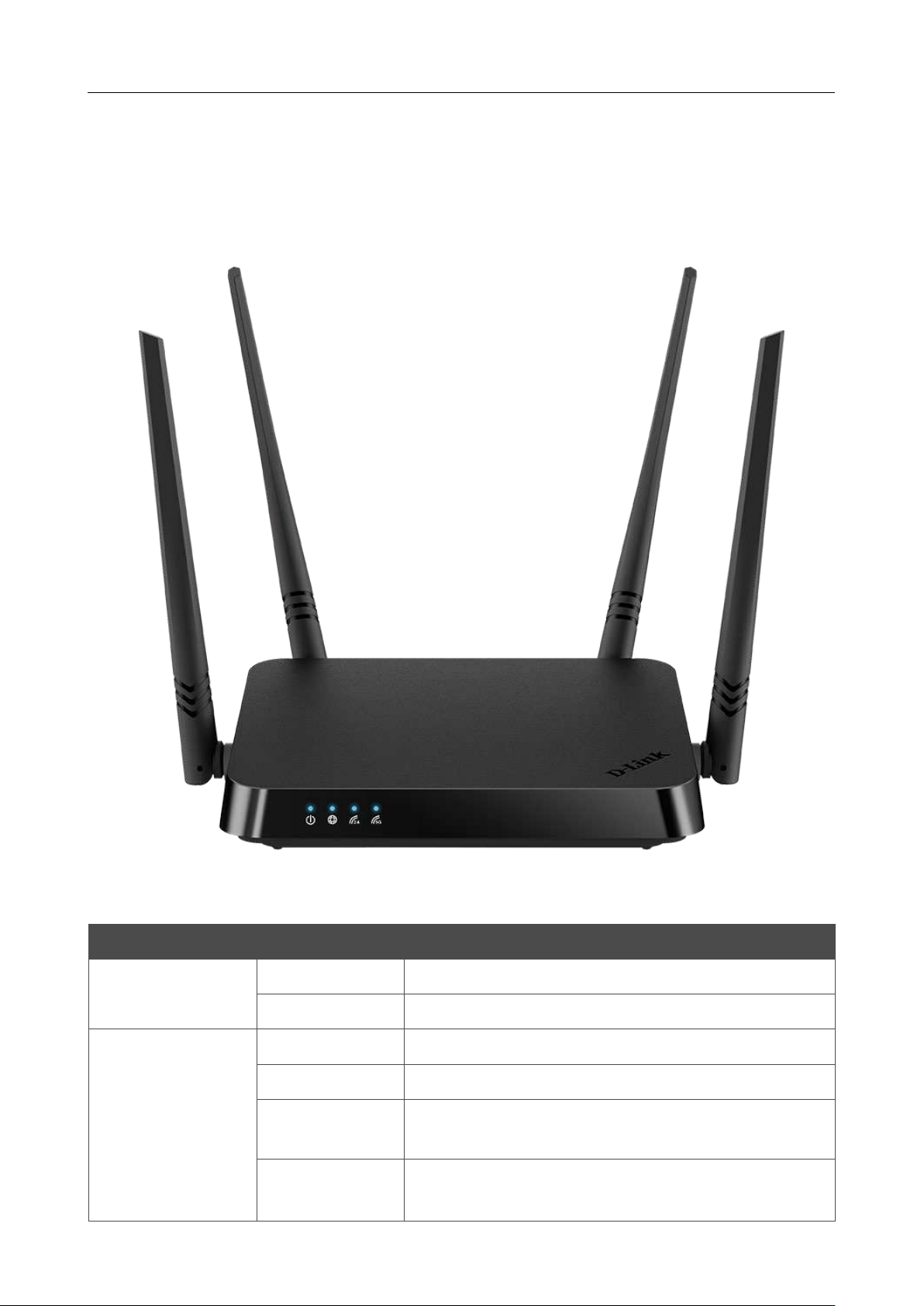
Product Appearance
Front Panel
Figure 1. Front panel view.
LED Mode Description
Power
Solid blue
The router is powered on.
No light
The router is powered off.
Internet
Solid blue
The default WAN connection is on.
Slow blinking blue
The firmware is being updated.
Fast blinking blue
The device is in the emergency mode. Restore the
factory default settings via the hardware RESET button.
No light
No WAN connection created or the default WAN
connection is off.

DIR-842V2 AC1200 Wi-Fi Gigabit Router
User Manual
Overview
Page 17 of 200
LED Mode Description
WLAN 2.4G
WLAN 5G
Solid blue
The router's WLAN of the relevant band is on.
Blinking blue
Data transfer through the Wi-Fi network of the relevant
band.
No light
The router's WLAN of the relevant band is off.
DIR-842V2 AC1200 Wi-Fi Gigabit Router
User Manual
Overview
Page 18 of 200
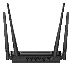
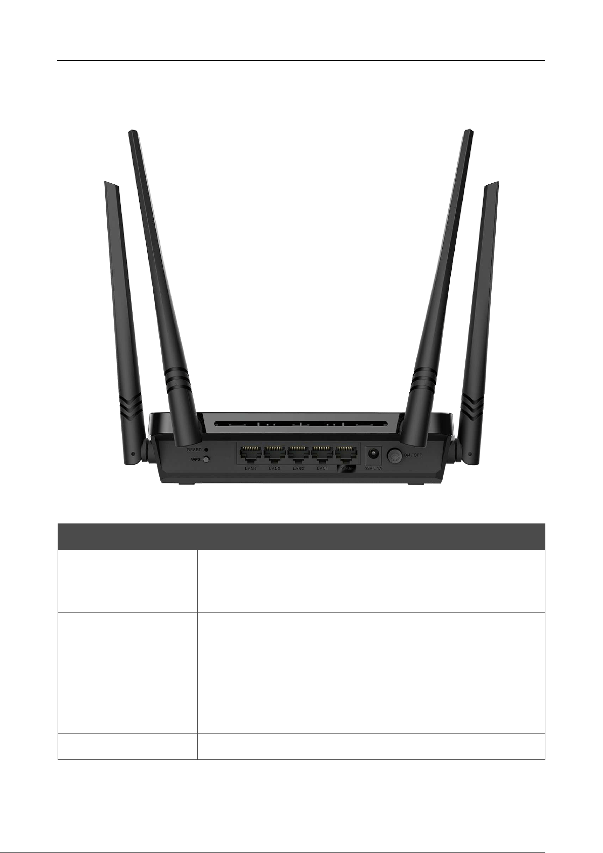
Back Panel
Figure 2. Back panel view.
Name Description
RESET
A button to restore the factory defaults.
To restore the factory defaults, push the button (with the device turned
on), hold it for 10 seconds, and then release the button.
WPS
A button to set up wireless connection (the WPS function).
To use the WPS function: with the device turned on, push the button,
hold it for 2 seconds, and release.
To disable the router's wireless network: with the device turned on,
push the button, hold it for 10 seconds, and release. The WLAN 2.4G
and WLAN 5G LEDs should turn off.
LAN 1-4
4 Ethernet ports to connect computers or network devices.

DIR-842V2 AC1200 Wi-Fi Gigabit Router
User Manual
Overview
Page 19 of 200
Name Description
WAN
A port to connect
to a cable or DSL modem or to a private Ethernet
line
(it is recommended to use the cable included in the delivery package).
12V=1A
Power connector.
ON/OFF
A button to turn the router on/off.
The device is also equipped with four external non-detachable Wi-Fi antennas.

DIR-842V2 AC1200 Wi-Fi Gigabit Router
User Manual
Overview
Page 20 of 200
Delivery Package
The following should be included:
• Router DIR-842V2
• Power adapter DC 12V/A
• Ethernet cable
• “Quick Installation Guide” (brochure).
The “User Manual” and “Quick Installation Guide” documents are available on D-Link website
(see
www.dlink.ru).
!
Using a power supply with a different voltage rating than the one included will cause
damage and void the warranty for this product.

DIR-842V2 AC1200 Wi-Fi Gigabit Router
User Manual
Installation and Connection
Page 21 of 200
CHAPTER 3. INSTALLATION AND CONNECTION
Before You Begin
Please, read this manual prior to installing the device. Make sure that you have all the necessary
information and equipment.
Computer or Mobile Device
Configuration of the wireless dual band gigabit router with a built-in 4-port switch
DIR-842V2
(hereinafter referred to as “the router”) is performed via the built-in web-based interface. The web-
based interface is available from any operating system that supports a web browser.
Also you can use D-Link Assistant application for Android or iPhone mobile devices (smartphones
or tablets).
PC Web Browser
The following PC web browsers are recommended:
• Apple Safari 8 and later
• Google Chrome 48 and later
• Microsoft Internet Explorer 10 and later
• Microsoft Edge 20.10240 and later
• Mozilla Firefox 44 and later
• Opera 35 and later.
For successful operation, JavaScript should be enabled on the web browser. Make sure that JavaScript
has not been disabled by other software (such as virus protection or web user security packages)
running on your computer.
Wired or Wireless NIC (Ethernet or Wi-Fi Adapter)
Any computer that uses the router should be equipped with an Ethernet or Wi-Fi adapter (NIC). If
your computer is not equipped with such a device, install an Ethernet or Wi-Fi adapter prior to using
the router.
Wireless Connection
Wireless workstations from your network should be equipped with a wireless 802.11a, b, g, n, or ac
NIC (Wi-Fi adapter). In addition, you should specify the values of SSID, channel number and security
settings defined in the web-based interface of the router for all these wireless workstations.

DIR-842V2 AC1200 Wi-Fi Gigabit Router
User Manual
Installation and Connection
Page 22 of 200
Connecting to PC
PC with Ethernet Adapter
1. Connect an Ethernet cable between any of LAN ports located on the back panel of the router
and the Ethernet port of your PC.
2. Connect the power cord to the power connector port on the back panel of the router, then
plug the power adapter into an electrical outlet or power strip.
3. Turn on the router by pressing the ON/OFF button on its back panel.
Then make sure that your PC is configured to obtain an IP address automatically (as DHCP client).
DIR-842V2 AC1200 Wi-Fi Gigabit Router
User Manual
Installation and Connection
Page 23 of 200
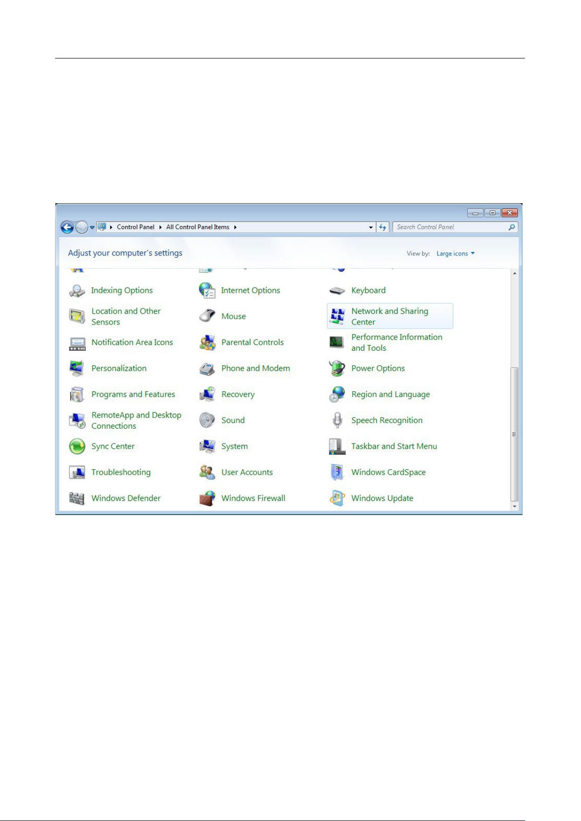
Obtaining IP Address Automatically (OS Windows 7)
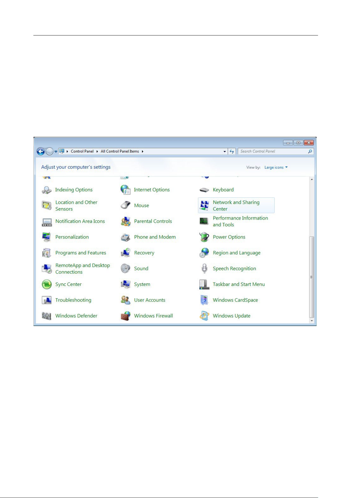
1. Click the Start button and proceed to the Control Panel window.
2. Select the Network and Sharing Center section. (If the Control Panel has the category
view (the Category value is selected from the View by drop-down list in the top right corner
of the window), choose the View network status and tasks line under the Network and
Internet section.)
Figure 3. The Control Panel window.
DIR-842V2 AC1200 Wi-Fi Gigabit Router
User Manual
Installation and Connection
Page 24 of 200
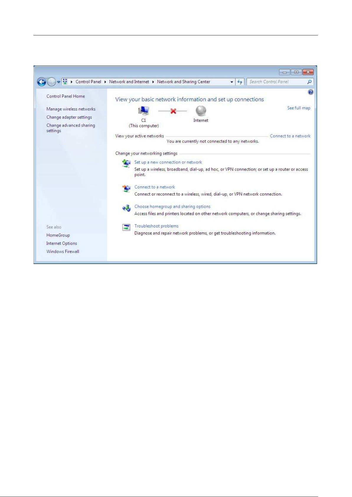
3. In the menu located on the left part of the window, select the Change adapter settings
line.
Figure 4. The Network and Sharing Center window.
DIR-842V2 AC1200 Wi-Fi Gigabit Router
User Manual
Installation and Connection
Page 25 of 200
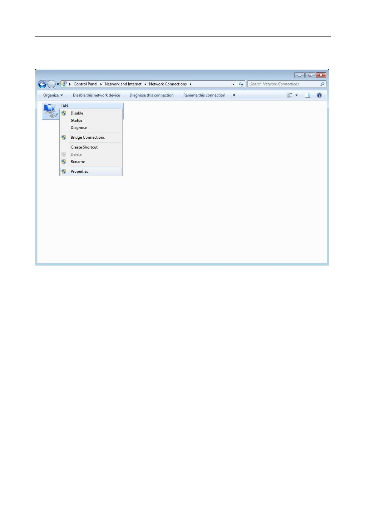
4. In the opened window, right-click the relevant Local Area Connection icon and select
the Properties line in the menu displayed.
Figure 5. The Network Connections window.
DIR-842V2 AC1200 Wi-Fi Gigabit Router
User Manual
Installation and Connection
Page 26 of 200
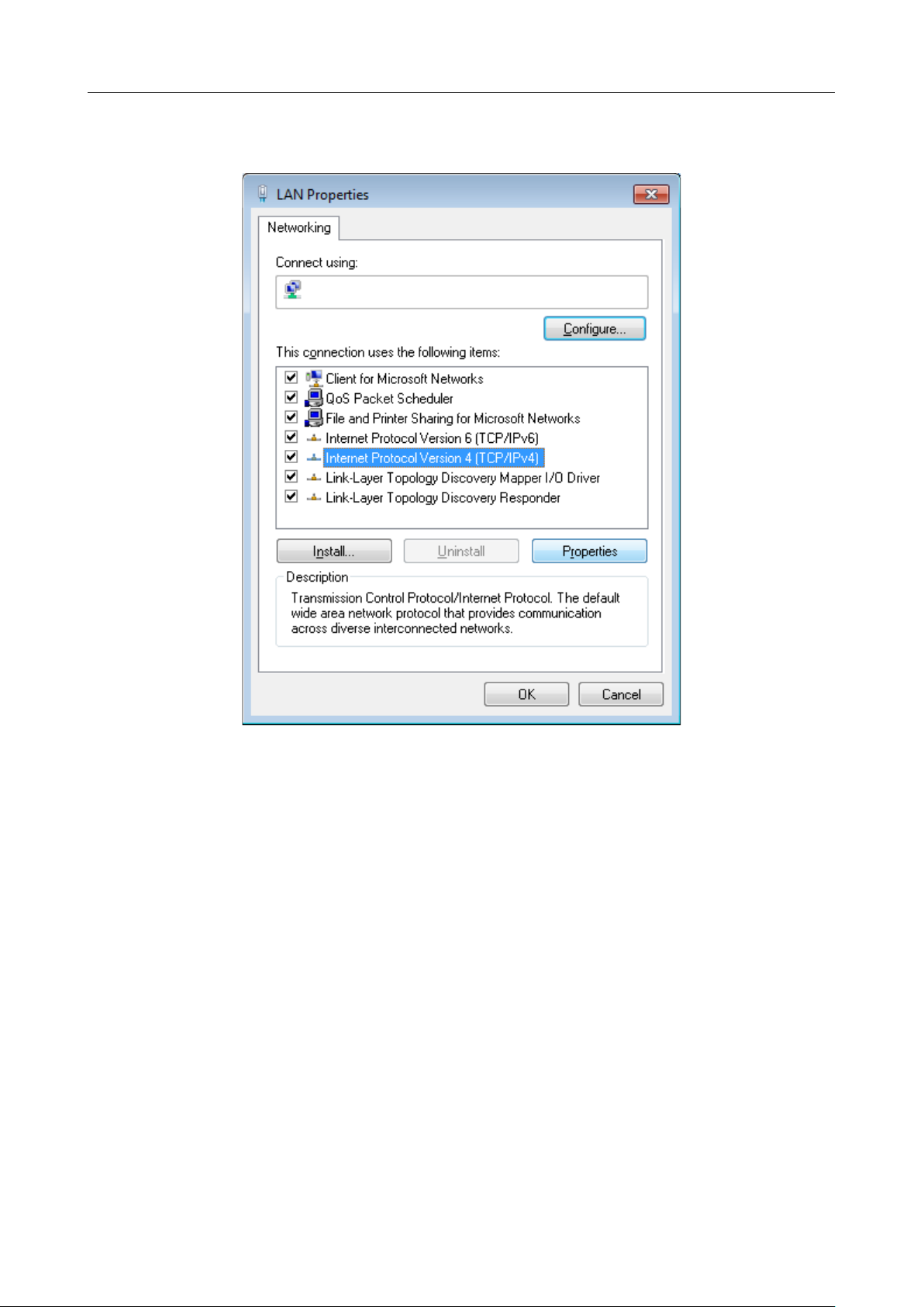
5. In the Local Area Connection Properties window, on the Networking tab, select the
Internet Protocol Version 4 (TCP/IPv4) line. Click the Properties button.
Figure 6. The Local Area Connection Properties window.
DIR-842V2 AC1200 Wi-Fi Gigabit Router
User Manual
Installation and Connection
Page 27 of 200
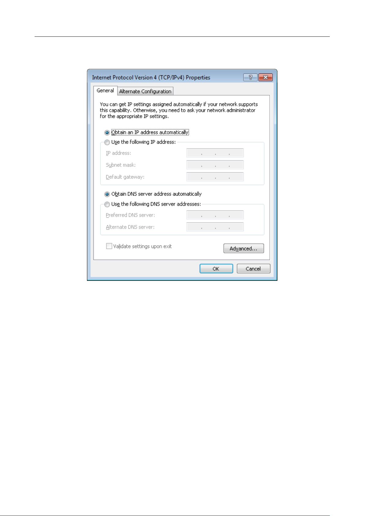
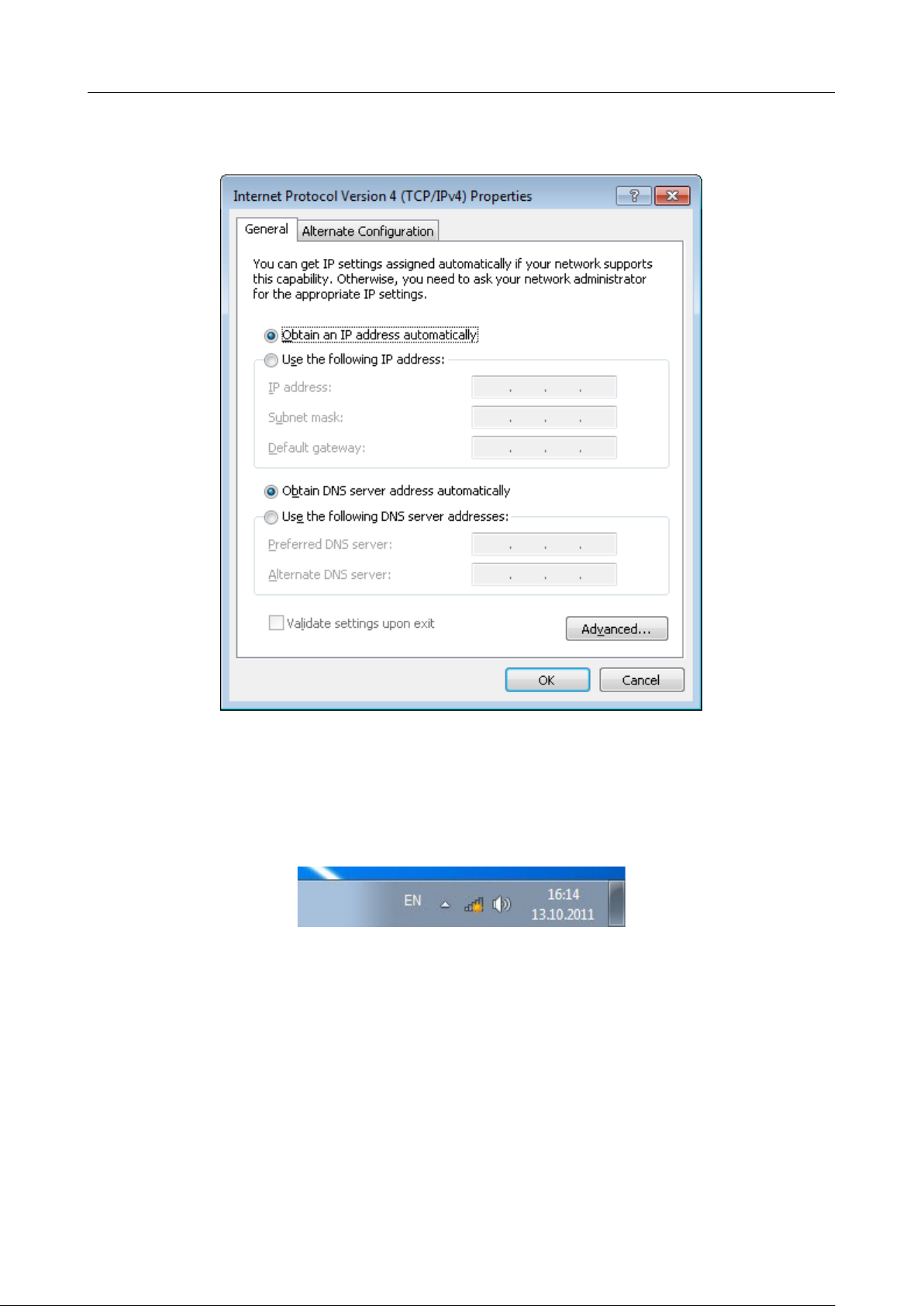
6. Make sure that the Obtain an IP address automatically and Obtain DNS server
address automatically choices of the radio buttons are selected. Click the OK button.
Figure 7. The Internet Protocol Version 4 (TCP/IPv4) Properties window.
7. Click the OK button in the connection properties window.
DIR-842V2 AC1200 Wi-Fi Gigabit Router
User Manual
Installation and Connection
Page 28 of 200
Obtaining IP Address Automatically (OS Windows 10)
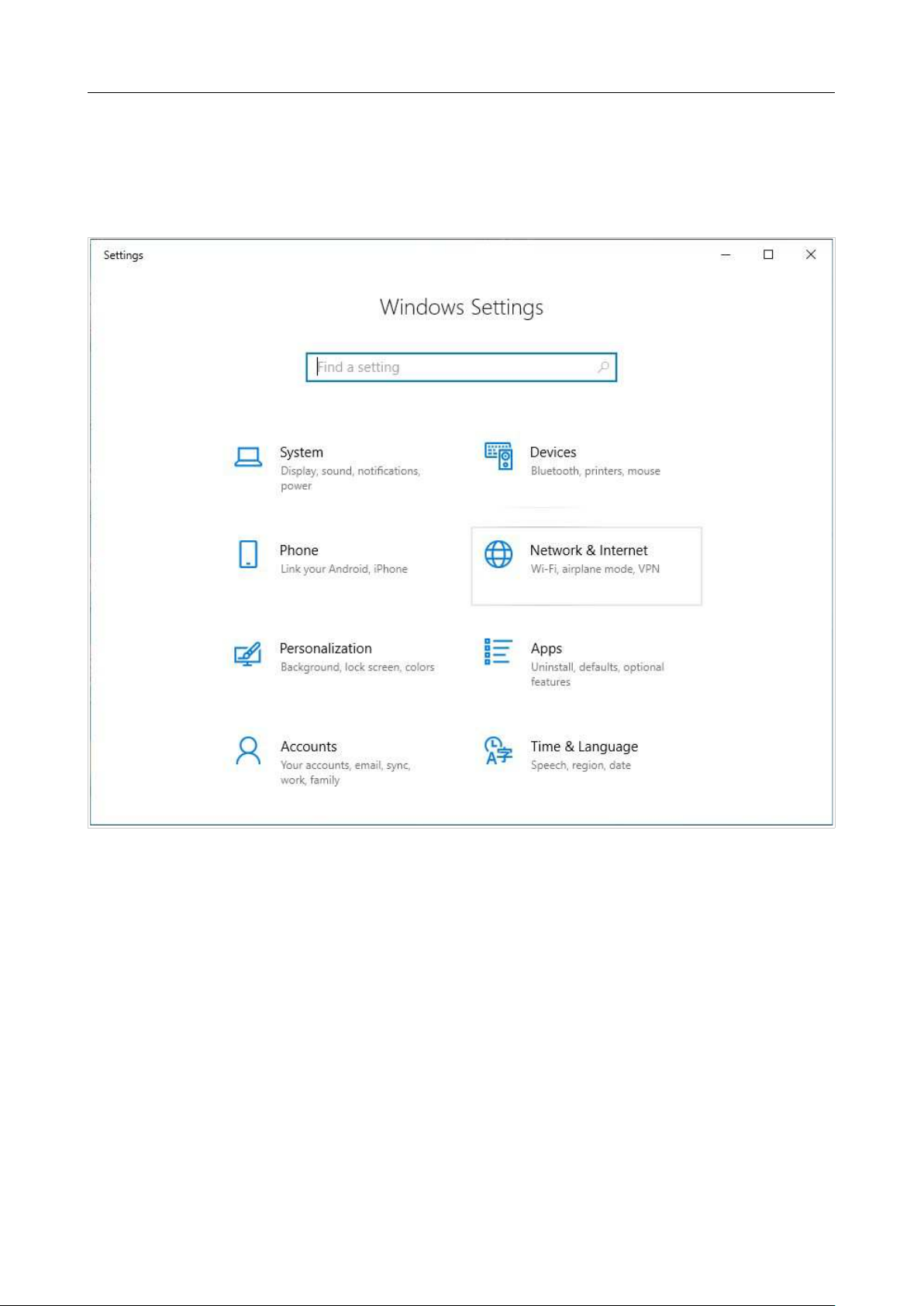
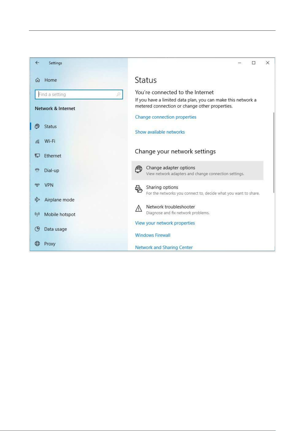
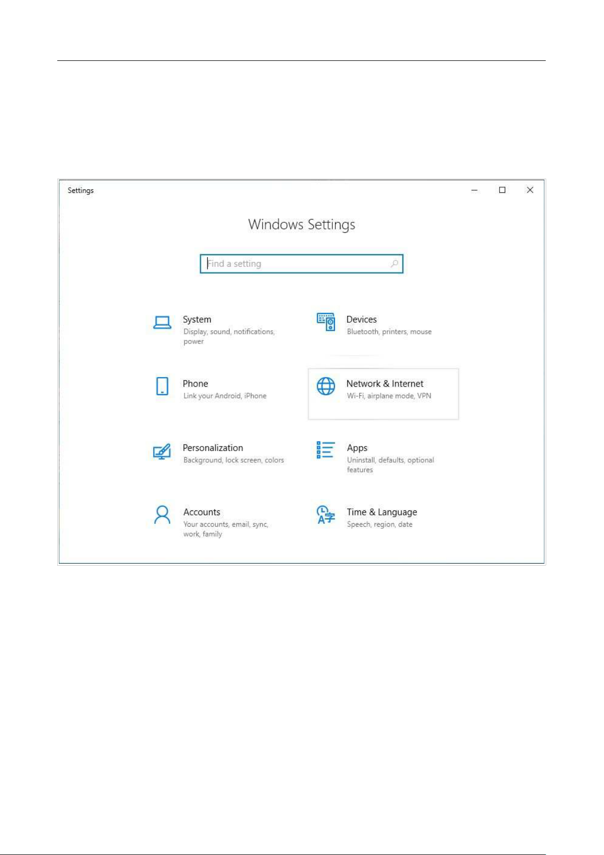
1. Click the Start button and proceed to the Settings window.
2. Select the Network & Internet section.
Figure 8. The Windows Settings window.
DIR-842V2 AC1200 Wi-Fi Gigabit Router
User Manual
Installation and Connection
Page 29 of 200
3. In the Change your network settings section, select the Change adapter options
line.
Figure 9. The Network & Internet window.
DIR-842V2 AC1200 Wi-Fi Gigabit Router
User Manual
Installation and Connection
Page 30 of 200
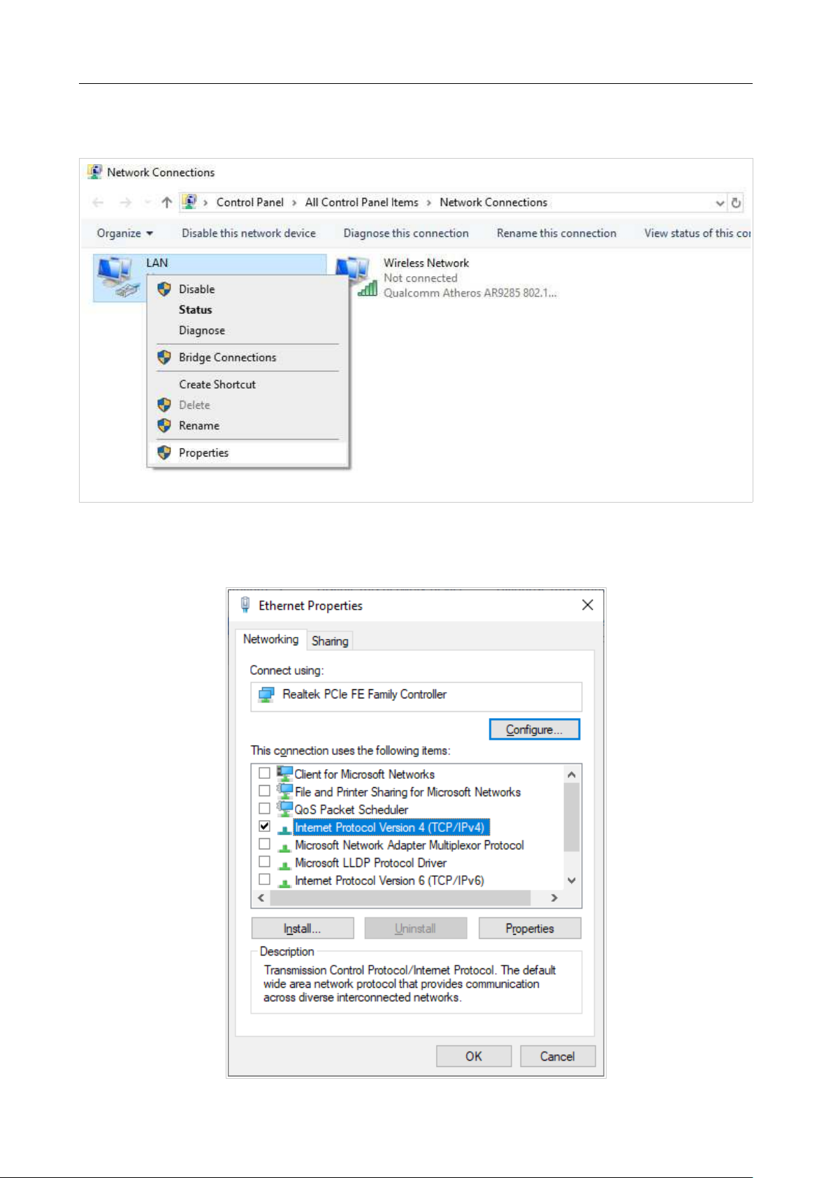
4. In the opened window, right-click the relevant Local Area Connection icon and select
the Properties line in the menu displayed.
Figure 10. The Network Connections window.
5. In the Local Area Connection Properties window, on the Networking tab, select the
Internet Protocol Version 4 (TCP/IPv4) line. Click the Properties button.
Figure 11. The local area connection properties window.
DIR-842V2 AC1200 Wi-Fi Gigabit Router
User Manual
Installation and Connection
Page 31 of 200
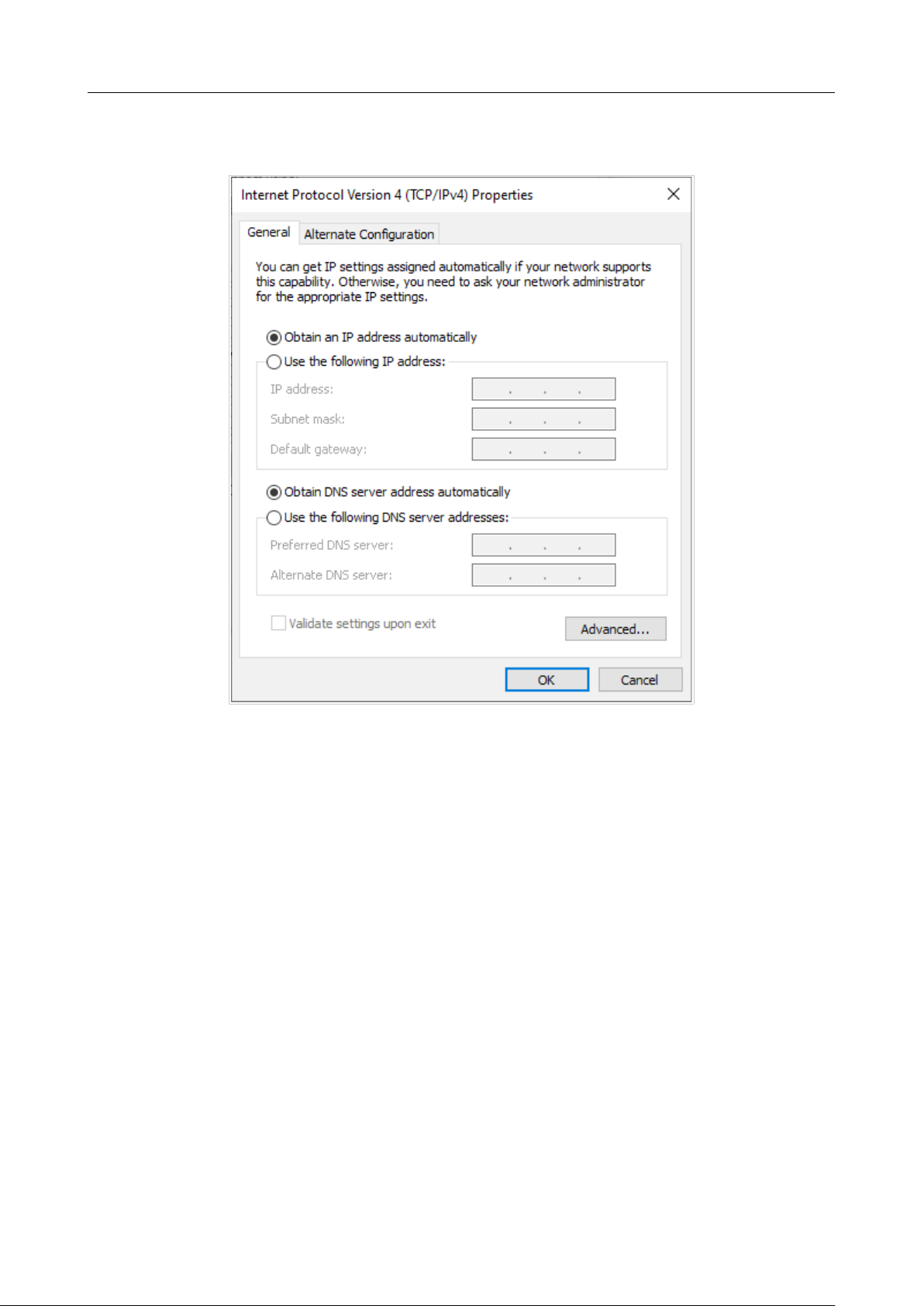
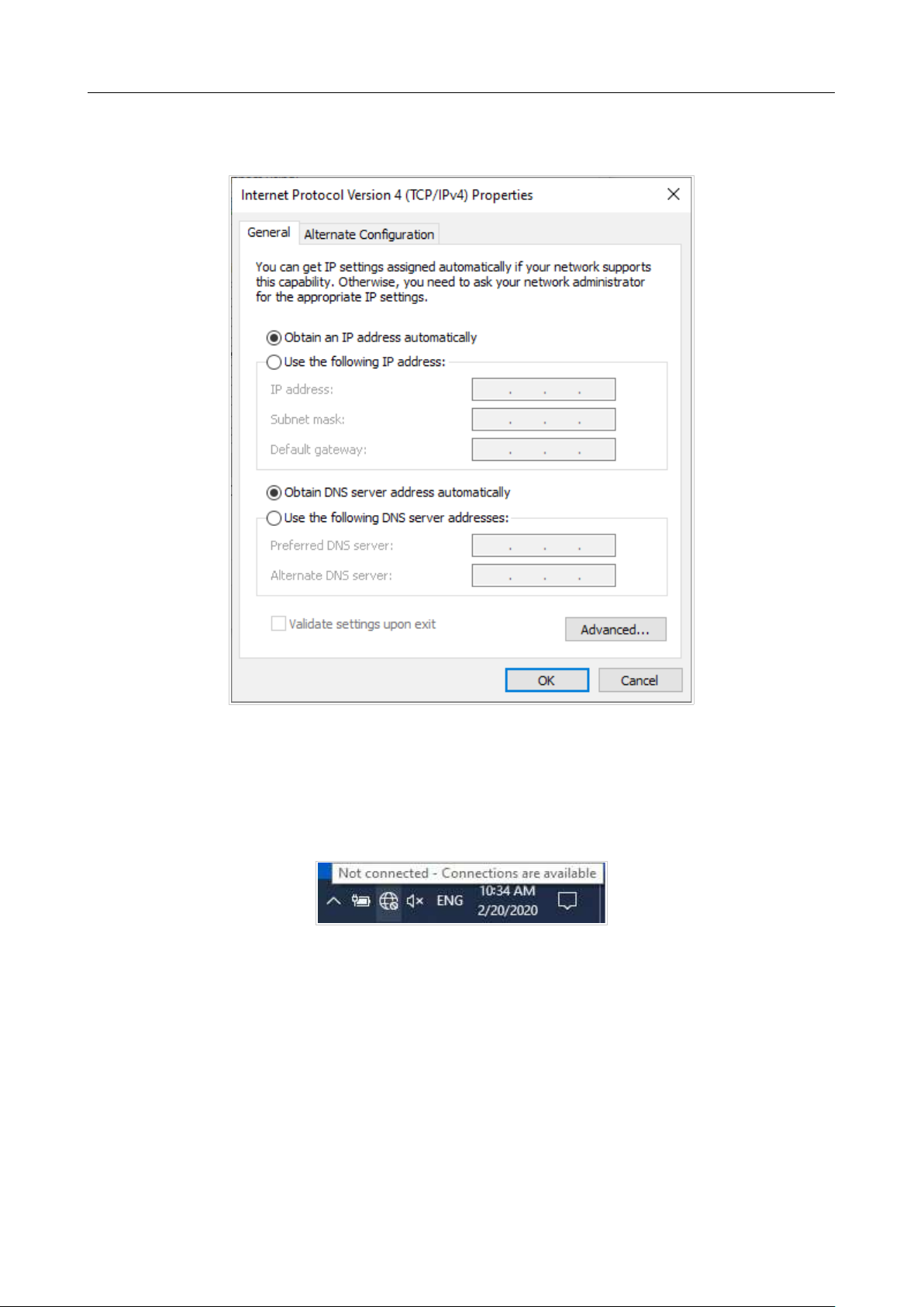
6. Make sure that the Obtain an IP address automatically and Obtain DNS server
address automatically choices of the radio buttons are selected. Click the OK button.
Figure 12. The Internet Protocol Version 4 (TCP/IPv4) Properties window.
7. Click the Close button in the connection properties window.

DIR-842V2 AC1200 Wi-Fi Gigabit Router
User Manual
Installation and Connection
Page 32 of 200
PC with Wi-Fi Adapter
1. Connect the power cord to the power connector port on the back panel of the router, then plug
the power adapter into an electrical outlet or power strip.
2. Turn on the router by pressing the ON/OFF button on its back panel.
3. Make sure that your Wi-Fi adapter is on. As a rule, modern notebooks with built-in wireless
NICs are equipped with a button or switch that turns on/off the wireless adapter (refer to your
PC documents). If your PC is equipped with a pluggable wireless NIC, install the software
provided with your Wi-Fi adapter.
Then make sure that your Wi-Fi adapter is configured to obtain an IP address automatically (as DHCP
client).
DIR-842V2 AC1200 Wi-Fi Gigabit Router
User Manual
Installation and Connection
Page 33 of 200
Obtaining IP Address Automatically
and Connecting to Wireless
Network (OS Windows 7)
1. Click the Start button and proceed to the Control Panel window.
2. Select the Network and Sharing Center section. (If the Control Panel has the category
view (the Category value is selected from the View by drop-down list in the top right corner
of the window), choose the View network status and tasks line under the Network and
Internet section.)
Figure 13. The Control Panel window.
3. In the menu located on the left part of the window, select the Change adapter settings
line.
4. In the opened window, right-click the relevant Wireless Network Connection icon. Make
sure that your Wi-Fi adapter is on, then select the Properties line in the menu displayed.
5. In the Wireless Network Connection Properties window, on the Networking tab,
select the Internet Protocol Version 4 (TCP/IPv4) line. Click the Properties button.
DIR-842V2 AC1200 Wi-Fi Gigabit Router
User Manual
Installation and Connection
Page 34 of 200
6. Make sure that the Obtain an IP address automatically and Obtain DNS server
address automatically choices of the radio buttons are selected. Click the OK button.
Figure 14. The Internet Protocol Version 4 (TCP/IPv4) Properties window.
7. Click the OK button in the connection properties window.
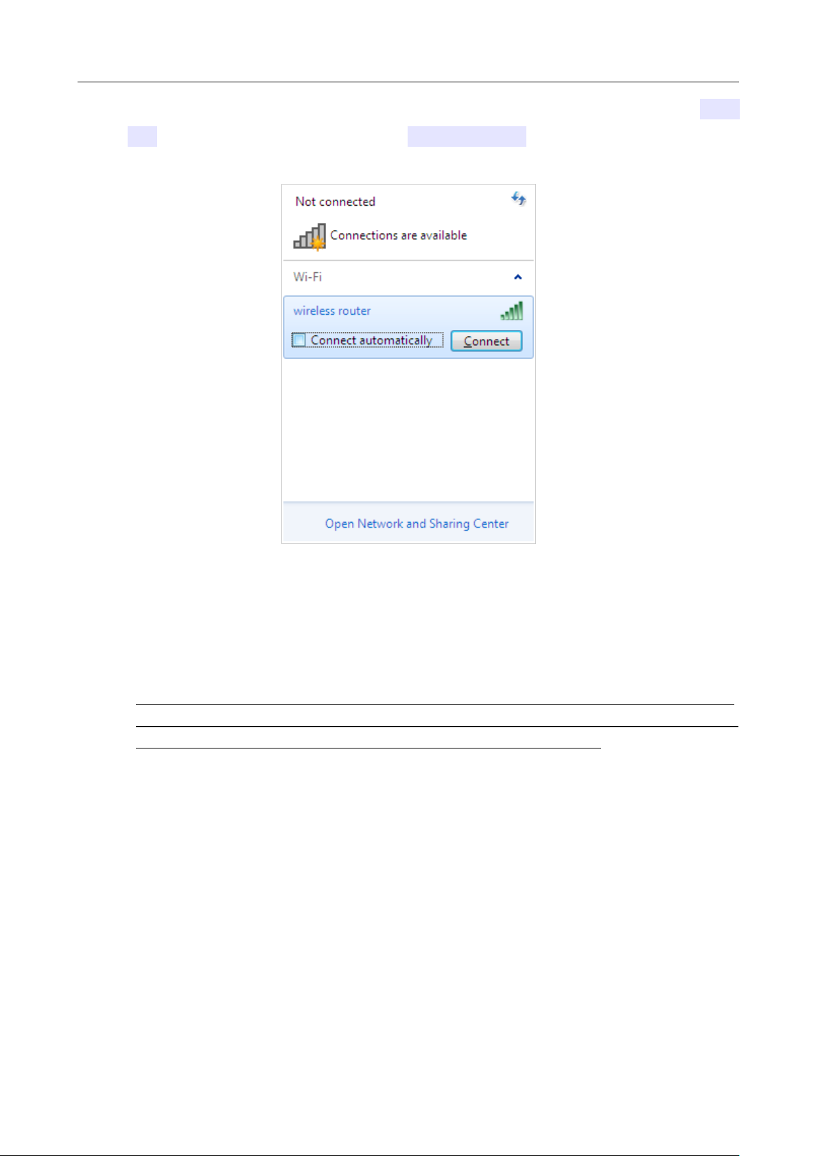
8. To open the list of available wireless networks, select the icon of the wireless network
connection and click the Connect To button or left-click the network icon in the notification
area located on the right side of the taskbar.
Figure 15. The notification area of the taskbar.
DIR-842V2 AC1200 Wi-Fi Gigabit Router
User Manual
Installation and Connection
Page 35 of 200
9. In the opened Wireless Network Connection window, select the wireless network DIR-
842 (for operating in the 2.4GHz band) or DIR-842V2-5G (for operating in the 5GHz band)
and click the Connect button.
Figure 16. The list of available networks.
10. In the opened window, enter the network key (see WPS PIN on the barcode label on the
bottom panel of the device) in the Security key field and click the OK button.
11. Wait for about 20-30 seconds. After the connection is established, the network icon will be
displayed as the signal level scale.
!
If you perform initial configuration of the router via Wi-Fi connection, note that
immediately after changing the wireless default settings of the router you will need to
reconfigure the wireless connection using the newly specified settings.
DIR-842V2 AC1200 Wi-Fi Gigabit Router
User Manual
Installation and Connection
Page 36 of 200
Obtaining IP Address Automatically
and Connecting to Wireless
Network (OS Windows 10)
1. Click the Start button and proceed to the Settings window.
2. Select the Network & Internet section.
Figure 17. The Windows Settings window.
3. In the Change your network settings section, select the Change adapter options
line.
4. In the opened window, right-click the relevant Wireless Network Connection icon. Make
sure that your Wi-Fi adapter is on, then select the Properties line in the menu displayed.
5. In the Wireless Network Connection Properties window, on the Networking tab,
select the Internet Protocol Version 4 (TCP/IPv4) line. Click the Properties button.
DIR-842V2 AC1200 Wi-Fi Gigabit Router
User Manual
Installation and Connection
Page 37 of 200
6. Make sure that the Obtain an IP address automatically and Obtain DNS server
address automatically choices of the radio buttons are selected. Click the OK button.
Figure 18. The Internet Protocol Version 4 (TCP/IPv4) Properties window.
7. Click the Close button in the connection properties window.
8. To open the list of available wireless networks, select the icon of the wireless network
connection and click the Connect To button or left-click the network icon in the notification
area located on the right side of the taskbar.
Figure 19. The notification area of the taskbar.
DIR-842V2 AC1200 Wi-Fi Gigabit Router
User Manual
Installation and Connection
Page 38 of 200
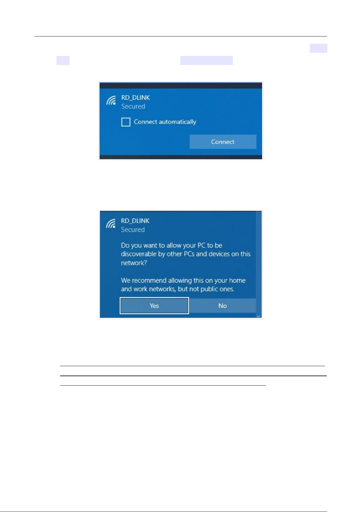
9. In the opened Wireless Network Connection window, select the wireless network DIR-
842 (for operating in the 2.4GHz band) or DIR-842V2-5G (for operating in the 5GHz band)
and click the Connect button.
Figure 20. The list of available networks.
10. In the opened window, enter the network key (see WPS PIN on the barcode label on the
bottom panel of the device) in the Security key field and click the Next button.
11. Allow or forbid your PC to be discoverable by other devices on this network (Yes / No).
Figure 21. PC discovery settings.
12. Wait for about 20-30 seconds. After the connection is established, the network icon will be
displayed as a dot with curved lines indicating the signal level.
!
If you perform initial configuration of the router via Wi-Fi connection, note that
immediately after changing the wireless default settings of the router you will need to
reconfigure the wireless connection using the newly specified settings.
DIR-842V2 AC1200 Wi-Fi Gigabit Router
User Manual
Installation and Connection
Page 39 of 200
Connecting to Web-based Interface
When you have configured your computer, you can access the web-based interface and configure
needed parameters (create a WAN connection, change the parameters of the wireless network, specify
the settings of the firewall, etc.).
!
For security reasons, DIR-842V2 with default settings cannot connect to the Internet. To
get
started, please set your own password used to access the web-based interface and, if
needed, configure other settings recommended by your ISP.
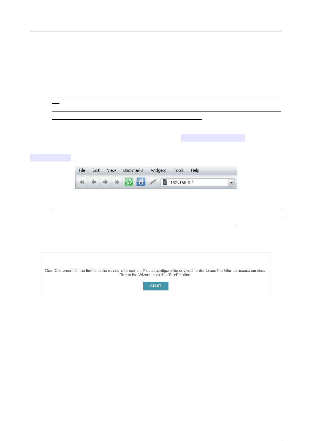
Start a web browser (see the Before You Begin section, page 18). In the address bar of the web
browser, enter the domain name of the router (by default, dlinkrouter.local) with a dot at
the end and press the Enter key. Also you can enter the IP address of the device (by default,
192.168.0.1).
Figure 22. Connecting to the web-based interface of the DIR-842V2 device.
!
If the error “The page cannot be displayed” (or “Unable to display the page”/“Could not
connect to remote server”) occurs upon connecting to the web-based interface of the router,
make sure that you have properly connected the router to your computer.
If the device has not been configured previously or the default settings have been restored, after access
to the web-based interface the Setup Wizard opens (see the Setup Wizard section, page 44).
Figure 23. The page for running the Setup Wizard.
DIR-842V2 AC1200 Wi-Fi Gigabit Router
User Manual
Installation and Connection
Page 40 of 200
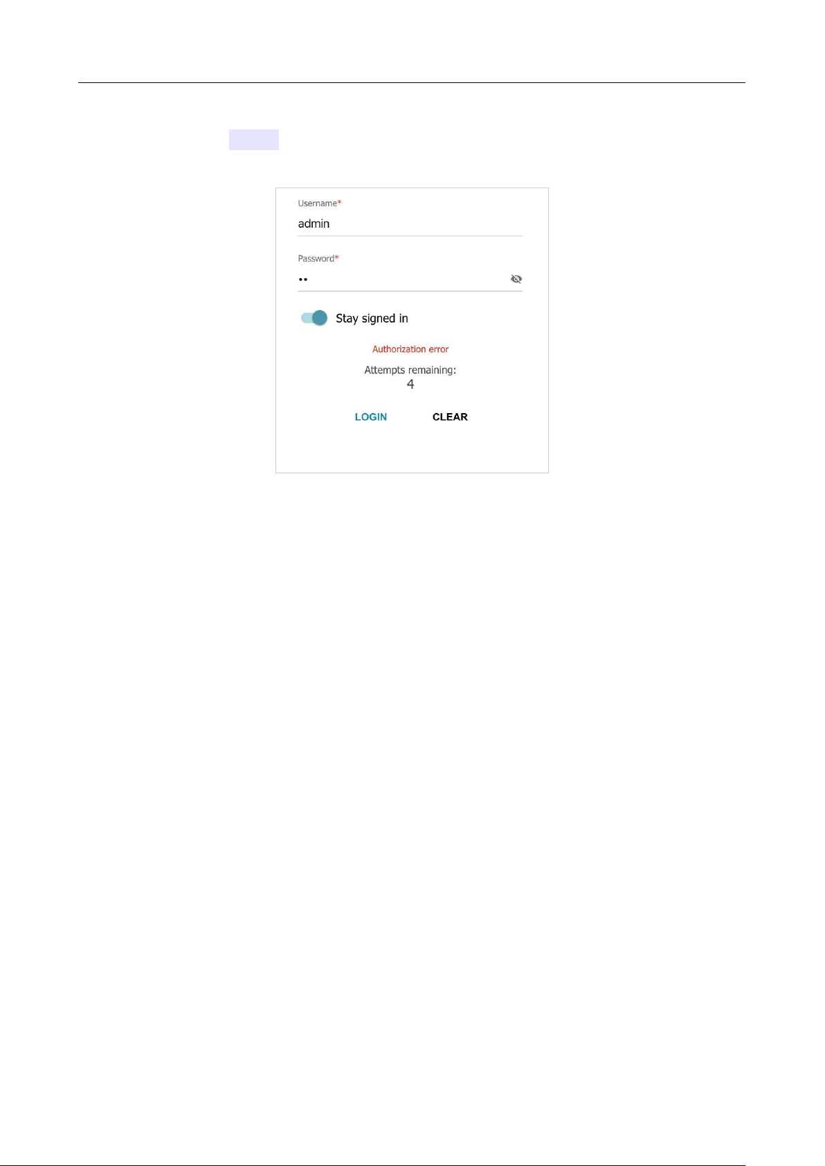
If you configured the device previously, after access to the web-based interface the login page opens.
Enter the username (admin) in the Username field and the password you specified in the
Password field, then click the LOGIN button.
Figure 24. The login page.
In order not to log out, move the Stay signed in switch to the right. After closing the web browser
or rebooting the device, you need to enter the username and the password again.
If you enter a wrong password several times, the web-based interface will be blocked for a while.
Please wait for one minute and reenter the password you specified.
DIR-842V2 AC1200 Wi-Fi Gigabit Router
User Manual
Installation and Connection
Page 41 of 200
Web-based Interface Structure
Home Page
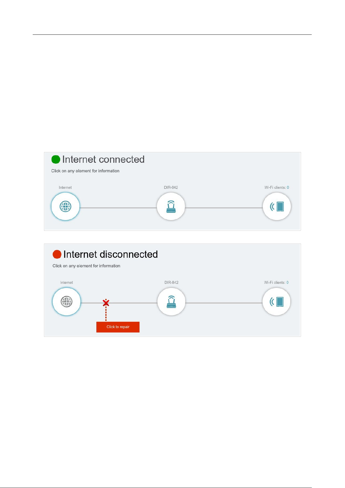
The Home page displays the current status of the router in the form of an interactive diagram. You
can click each icon to display information about each part of the network at the bottom of the screen.
The menu bar at the top of the page will allow you to quickly navigate to other pages.
The page displays whether or not the router is currently connected to the Internet. If it is disconnected,
click the sign Click to repair to go to the Settings / Internet / WAN page (for the description of
the page, see the WAN section, page 65).
Figure 25. The Home page. The device is connected to the Internet.
Figure 26. The Home page. The device is not connected to the Internet.
DIR-842V2 AC1200 Wi-Fi Gigabit Router
User Manual
Installation and Connection
Page 42 of 200
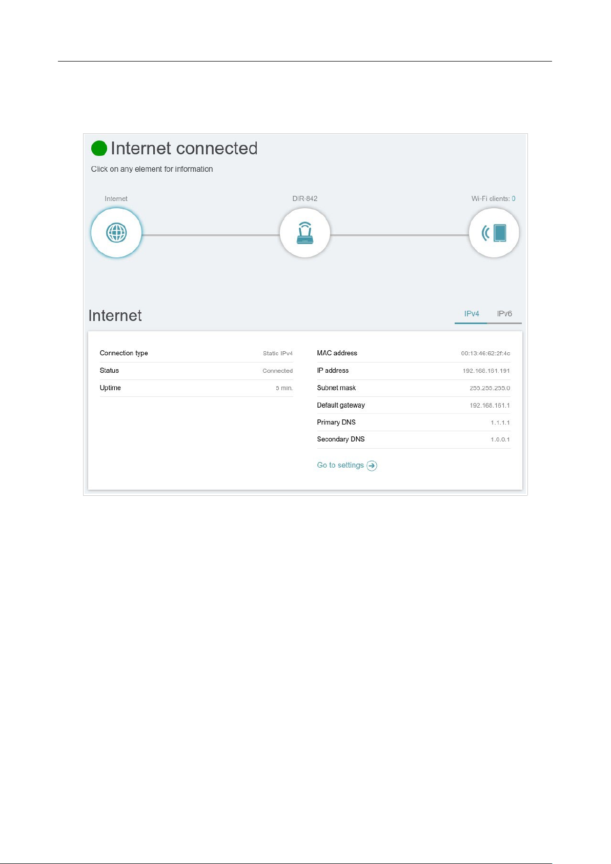
Internet Section
Click the Internet icon to view more details about your Internet connection.
Figure 27. The Home page. The Internet section.
Click IPv4 or IPv6 to display details of the IPv4 connection and IPv6 connection respectively.
To reconfigure the Internet settings, click Go to setting. Upon that the Settings / Internet /
WAN page opens (for the description of the page, see the WAN section, page 65).
DIR-842V2 AC1200 Wi-Fi Gigabit Router
User Manual
Installation and Connection
Page 43 of 200
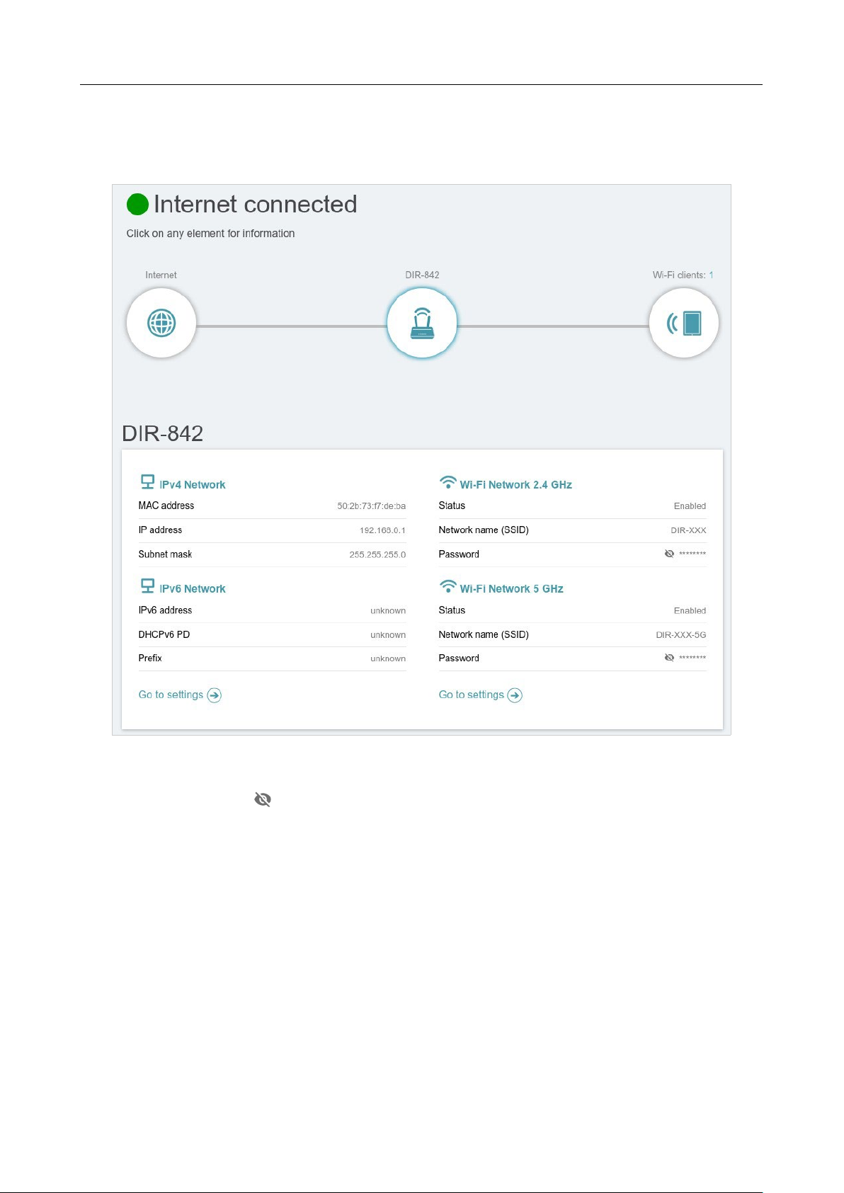
DIR-842V2 Section
Click the DIR-842V2 icon to view details about the router and its wireless settings.
Figure 28. The Home page. The DIR-842V2 section.
Here you can see the router’s current Wi-Fi network name in the 2.4GHz and 5GHz bands, the
password (click Show ( ) to display it), as well as the router's MAC address, IPv4 address, and
IPv6 address.
To reconfigure the network settings, either click Go to settings on the lower left, or click Settings
(at the top of the page) and then Network on the menu that appears (for the description of the page,
see the Settings / Network section, page 104).
To reconfigure the wireless settings, either click Go to settings on the lower right, or click
Settings (at the top of the page) and then Wireless Network on the menu that appears (for the
description of the page, see the Settings / Wireless network section, page 96).
DIR-842V2 AC1200 Wi-Fi Gigabit Router
User Manual
Installation and Connection
Page 44 of 200
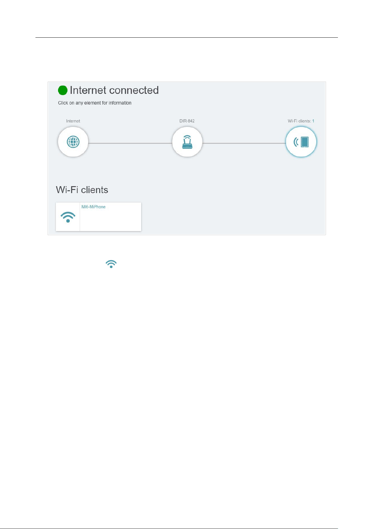
Wi-Fi Clients Section
Click the Wi-Fi clients icon to view details about wireless clients connected to the router.
Figure 29. The Home page. The Connected clients section.
Here you can see all wireless clients currently connected to the router. Such devices are marked by
the Connected icon ( ).

DIR-842V2 AC1200 Wi-Fi Gigabit Router
User Manual
Installation and Connection
Page 45 of 200
Menu Sections
To configure the router use the menu bar in the top part of the page.
The Settings section provides you with the most essential settings.
On the Setup Wizard page you can run the Setup Wizard. The Wizard allows you to configure the
router for operation in the needed mode and specify all parameters necessary for getting started (for
the description of the Wizard, see the Setup Wizard section, page 44).
On the Internet / WAN page you can create a connection to the Internet or reconfigure existing
connections (for the description of the page, see the WAN section, page 65).
On the WAN Failover page you can enable and configure the WAN backup function (for the
description of the page, see the Settings / WAN Failover section, page 94).
On the Wireless network page you can configure the basic and additional wireless networks (for
the description of the page, see the Settings / Wireless network section, page 96).
On the Network page you can configure basic parameters of the LAN interface of the router (for the
description of the page, see the Settings / Network section, page 104).
The pages of the Functions / Firewall subsection are designed for configuring the firewall of the
router (for the description of the pages, see the Functions / Firewall section, page 114).
The pages of the Functions / Wi-Fi subsection are designed for specifying all other settings of the
router's wireless network (for the description of the pages, see the Functions / Wi-Fi section, page
122).
The pages of the Functions / Advanced subsection are designed for configuring additional
parameters of the router (for the description of the pages, see the Functions / Advanced section, page
140).
The pages of the Management section provide functions for managing the internal system of the
router (for the description of the pages, see the Management section, page 166). And the pages of the
Management / Statistics subsection display data on the current state of the router (for the
description of the pages, see the Statistics section, page 185). Also the pages of the Management /
Yandex.DNS subsection are designed for configuring the Yandex.DNS web content filtering service
(for the description of the pages, see the Yandex.DNS section, page 174).

DIR-842V2 AC1200 Wi-Fi Gigabit Router
User Manual
Installation and Connection
Page 46 of 200
Notifications
The router's web-based interface displays notifications in the top right part of the page.
Figure 30. The web-based interface notifications.
Click the icon displaying the number of notifications to view the complete list and click the relevant
button.
DIR-842V2 AC1200 Wi-Fi Gigabit Router
User Manual
Configuring via Web-based Interface
Page 47 of 200
CHAPTER 4. CONFIGURING VIA WEB-BASED
INTERFACE
Setup Wizard
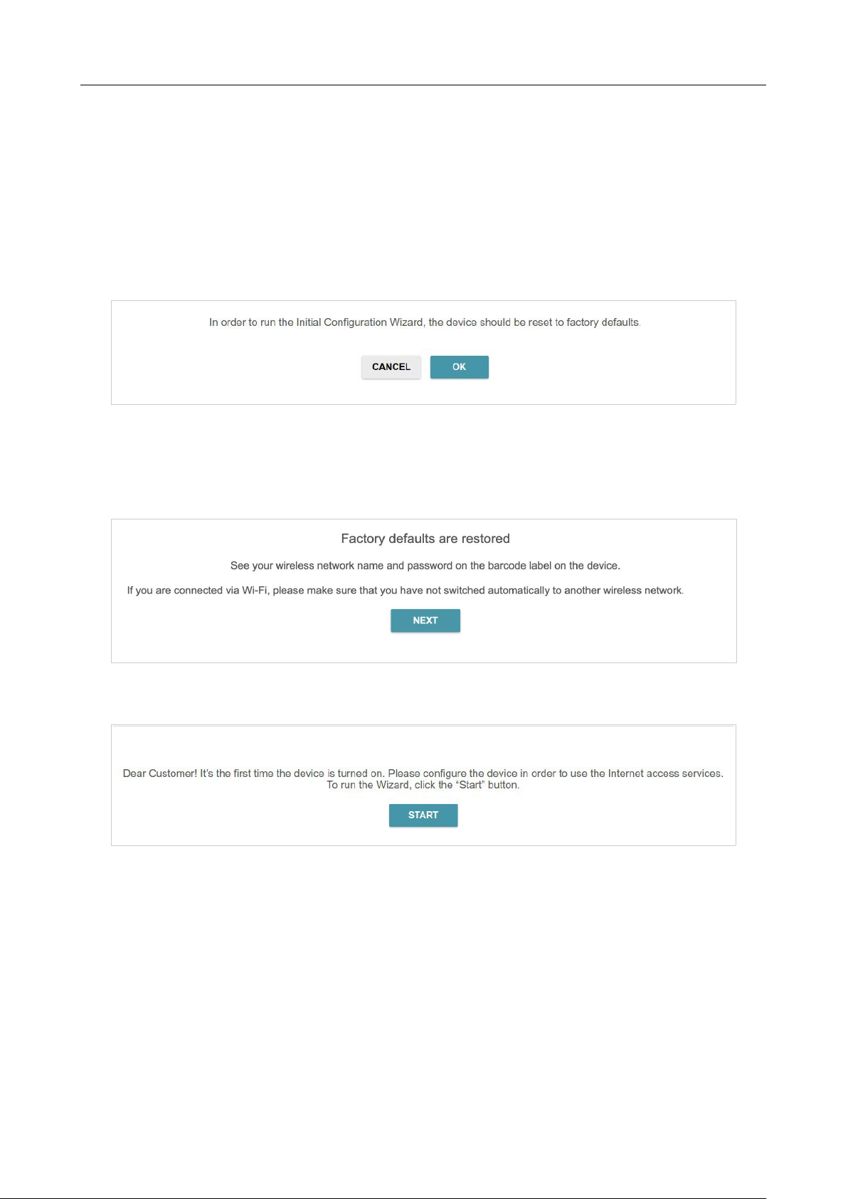
To start the Setup Wizard, go to the Settings / Setup Wizard section. On the opened page, click
the OK button and wait until the factory default settings are restored.
Figure 31. Restoring the default settings in the Wizard.
If you perform initial configuration of the router via Wi-Fi connection, please make sure that you
are connected to the wireless network of DIR-842V2 (see the WLAN name (SSID) on the barcode
label on the bottom panel of the device) and click the NEXT button.
Figure 32. Checking connection to the wireless network.
Click the START button.
Figure 33. Starting the Wizard.
DIR-842V2 AC1200 Wi-Fi Gigabit Router
User Manual
Configuring via Web-based Interface
Page 48 of 200
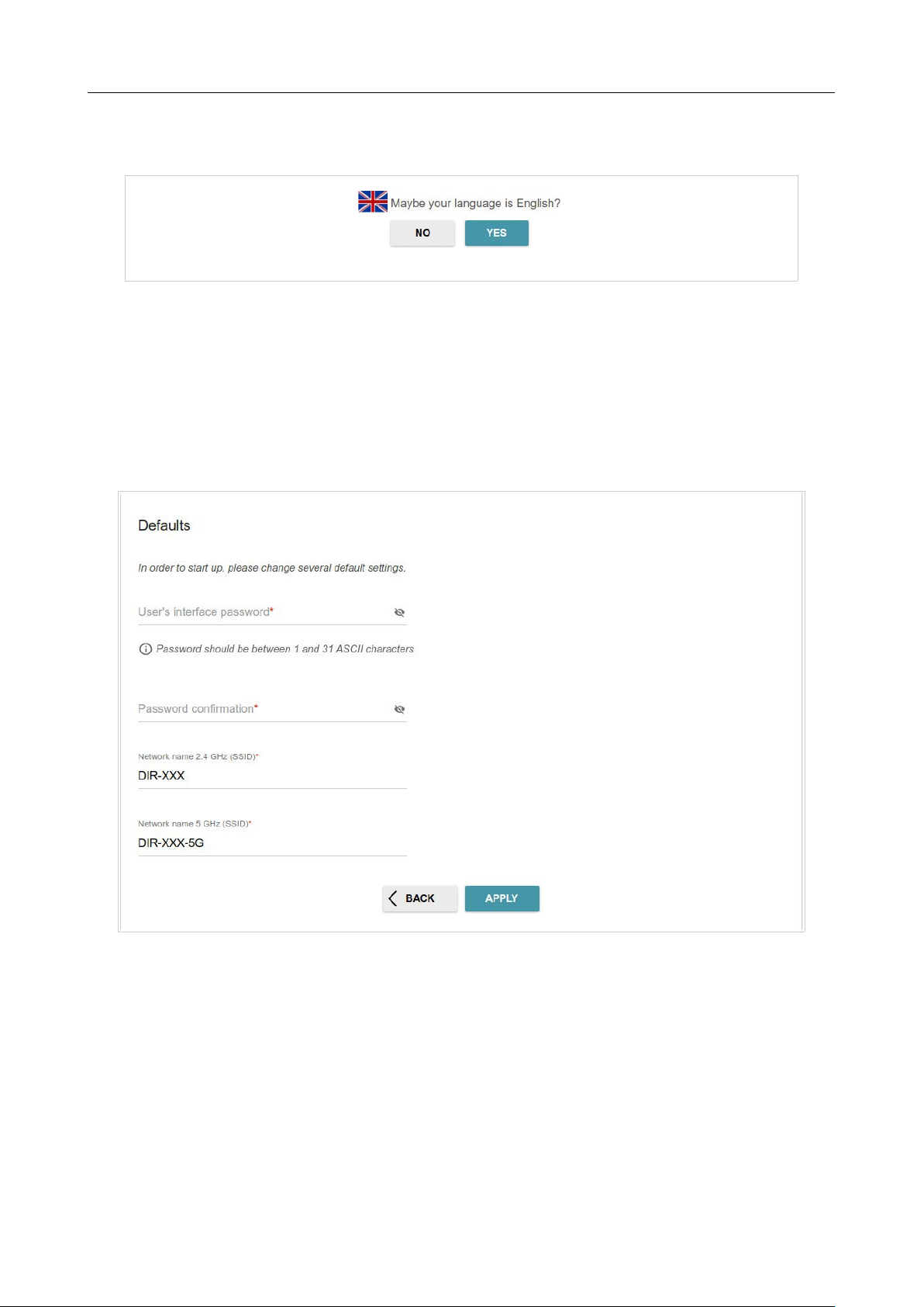
On the opened page, click YES in order to leave the current language of the web-based interface or
click NO to select another language.
Figure 34. Selecting a language.
You can finish the Wizard earlier and go to the menu of the web-based interface. To do this, click the
ADVANCED SETTINGS button. On the opened page, change the default settings: specify the
administrator password in the User’s interface password and Password confirmation fields
and the name of the wireless network in the 2.4GHz and 5GHz bands in the Network name 2.4
GHz (SSID) and Network name 5 GHz (SSID) fields correspondingly. Then click the APPLY
button.
Figure 35. Changing the default settings.
To continue the configuration of the router via the Wizard, click the CONTINUE button.
DIR-842V2 AC1200 Wi-Fi Gigabit Router
User Manual
Configuring via Web-based Interface
Page 49 of 200
Selecting Operation Mode
Select the needed operation mode and click the NEXT button.
Router
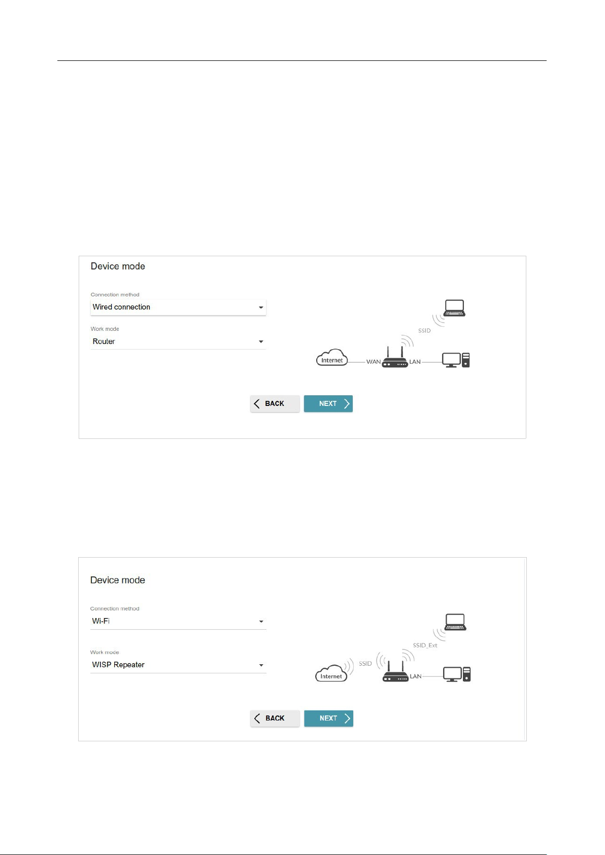
In order to connect your device to a wired ISP, on the Device mode page, from the Connection
method list, select the Wired connection value. Then from the Work mode list select the
Router value. In this mode you can configure a WAN connection, set your own settings for the
wireless network in the 2.4GHz and 5GHz bands, configure LAN ports to connect an STB or VoIP
phone, and set your own password for access to the web-based interface of the device.
Figure 36. Selecting an operation mode. The Router mode.
In order to connect your device to a wireless ISP (WISP), on the Device mode page, from the
Connection method list, select the Wi-Fi value. Then from the Work mode list select the WISP
Repeater value. In this mode you can connect your device to another access point, configure a WAN
connection, set your own settings for the wireless network in the 2.4GHz and 5GHz bands, and set
your own password for access to the web-based interface of the device.
Figure 37. Selecting an operation mode. The WISP Repeater mode.
DIR-842V2 AC1200 Wi-Fi Gigabit Router
User Manual
Configuring via Web-based Interface
Page 50 of 200
Access Point or Repeater
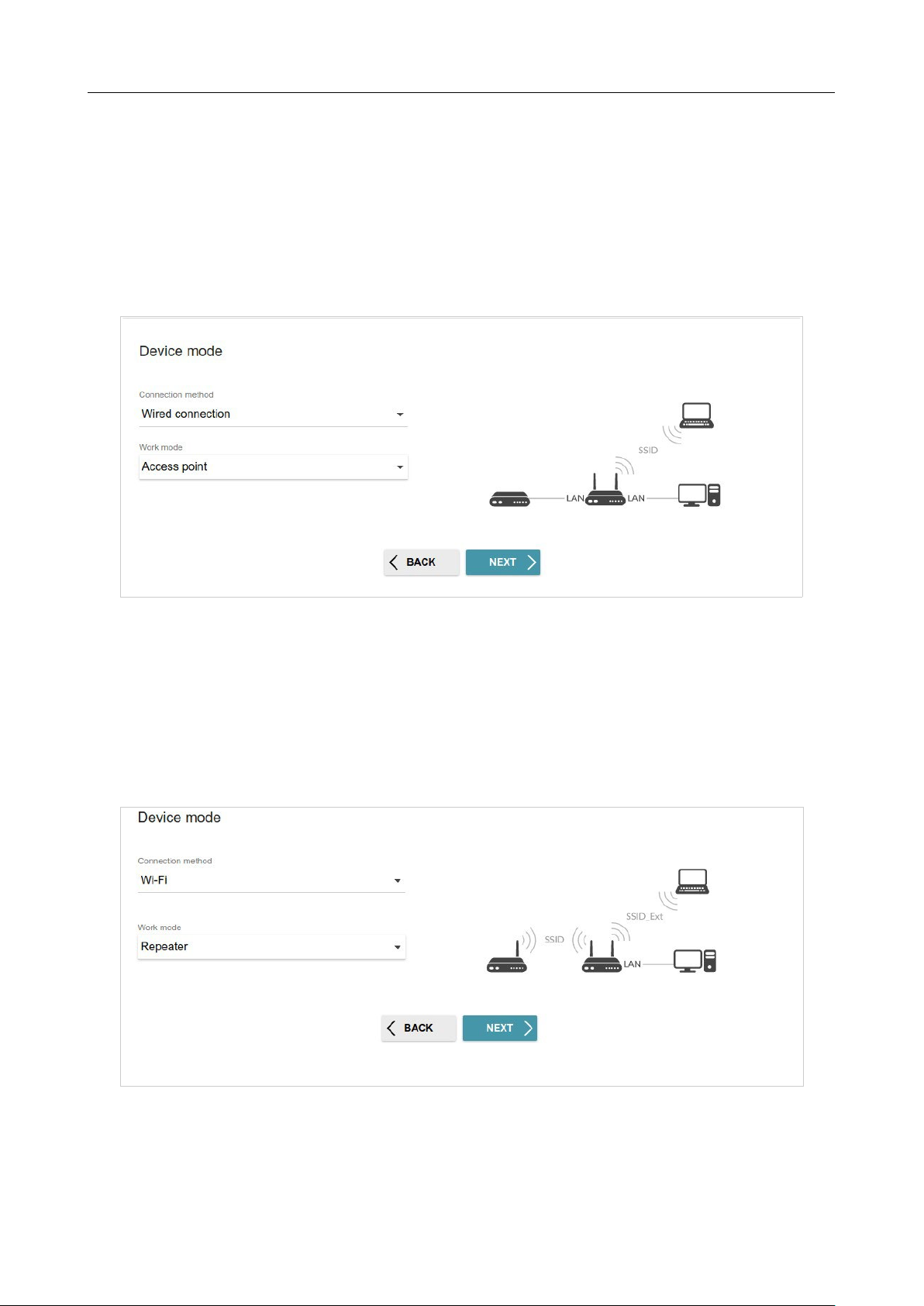
In order to connect your device to a wired router for adding a wireless network to the existing local
network, on the Device mode page, from the Connection method list, select the Wired
connection value. Then from the Work mode list select the Access point value. In this mode
you can change the LAN IP address, set your own settings for the wireless network in the 2.4GHz
and 5GHz bands and set your own password for access to the web-based interface of the device.
Figure 38. Selecting an operation mode. The Access point mode.
In order to connect your device to a wireless router for extending the range of the existing wireless
network, on the Device mode page, from the Connection method list, select the Wi-Fi value.
Then from the Work mode list select the Repeater value. In this mode you can change the LAN
IP address, connect your device to another access point, set your own settings for the wireless network
in the 2.4GHz and 5GHz bands, and set your own password for access to the web-based interface of
the device.
Figure 39. Selecting an operation mode. The Repeater mode.
DIR-842V2 AC1200 Wi-Fi Gigabit Router
User Manual
Configuring via Web-based Interface
Page 51 of 200
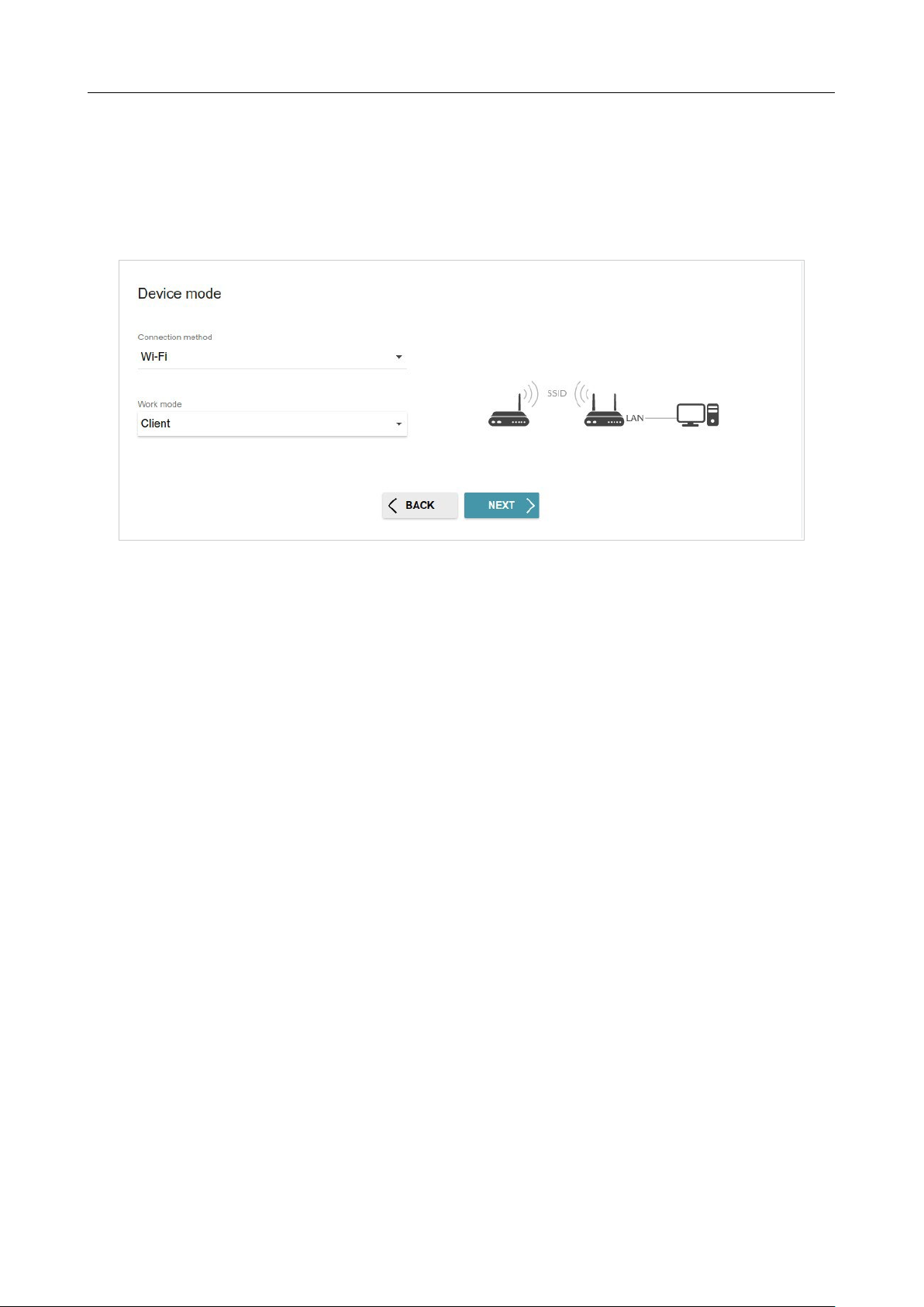
In order to let wired PCs connected to your device access the network of a wireless router, on the
Device mode page, from the Connection method list, select the Wi-Fi value. Then from the
Work mode list select the Client value. In this mode you can change the LAN IP address, connect
your device to another access point and set your own password for access to the web-based interface
of the device.
Figure 40. Selecting an operation mode. The Client mode.
When the operation mode is selected, click the NEXT button.
DIR-842V2 AC1200 Wi-Fi Gigabit Router
User Manual
Configuring via Web-based Interface
Page 52 of 200
Changing LAN IPv4 Address
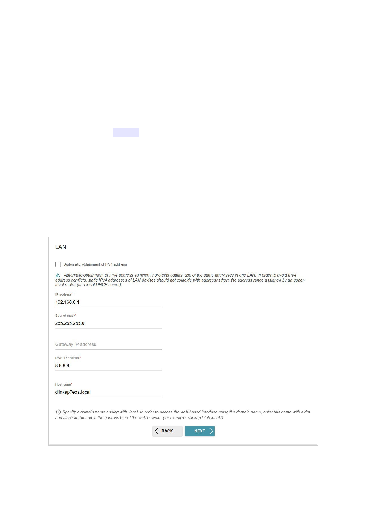
This configuration step is available for the Access point, Repeater, and Client modes.
1. Select the Automatic obtainment of IPv4 address to let DIR-842V2 automatically
obtain the LAN IPv4 address.
2. In the Hostname field, you should specify a domain name of the router using which you can
access the web-based interface after finishing the Wizard. Enter a new domain name of the
router ending with .local or leave the value suggested by the router.
In order to access the web-based interface using the domain name, in the address bar of the
web browser, enter the name of the router with a dot at the end.
If you want to manually assign the LAN IPv4 address for DIR-842V2, do not select the Automatic
obtainment of IPv4 address checkbox and fill in the IP address, Subnet mask, DNS IP
address, Hostname fields and, if needed, the Gateway IP address field. Make sure that the
assigned address does not coincide with the LAN IPv4 address of the router to which your device
connects.
Figure 41. The page for
changing the LAN IPv4 address.
3. Click the NEXT button to continue or click the BACK button to return to the previous page.
!
DIR-842V2 AC1200 Wi-Fi Gigabit Router
User Manual
Configuring via Web-based Interface
Page 53 of 200
Wi-Fi Client
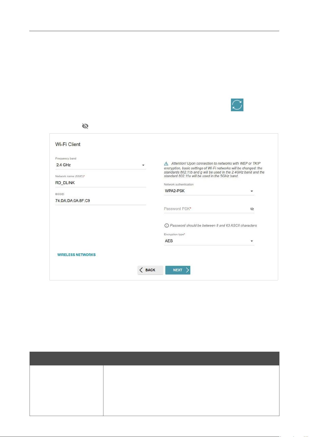
This configuration step is available for the WISP Repeater, Repeater, and Client modes.
1. On the Wi-Fi Сlient page, click the WIRELESS NETWORKS button and select the
network to which you want to connect in the opened window. When you select a network, the
Network name (SSID) and BSSID fields are filled in automatically.
If you cannot find the needed network in the list, click the UPDATE LIST icon ( ).
2. If a password is needed to connect to the selected network, fill in the relevant field. Click the
Show icon ( ) to display the entered password.
Figure 42. The page for configuring the Wi-Fi client.
If you connect to a hidden network, select the band where the hidden network operates from the
Frequency band list and enter the network name in the Network name (SSID) field. Then select
a needed value from the Network authentication list and then, if needed, enter the password in
the relevant field.
When the Open or WEP authentication type is selected, the following settings are displayed on the
page:
Parameter Description
Enable encryption WEP
For Open authentication type only.
The checkbox activating WEP encryption. When the checkbox is
selected, the Default key ID drop-down list, the
Encryption key
WEP as HEX checkbox, and four Encryption key fields
are
displayed on the page.

DIR-842V2 AC1200 Wi-Fi Gigabit Router
User Manual
Configuring via Web-based Interface
Page 54 of 200
Parameter Description
Default key ID
The number of the key (from first to fourth) which will be used for
WEP encryption.
Encryption key WEP as
HEX
Select the checkbox to set a hexadecimal number as a key for
encryption.
Encryption key
(1-4)
Keys for WEP encryption. The router uses the key selected from the
Default key ID drop-down list. It is required to specify all the fields.
Click the Show icon ( ) to display the entered key.
When the WPA-PSK, WPA2-PSK, WPA-PSK/WPA2-PSK mixed, WPA3-SAE, or WPA2-
PSK/WPA3-SAE mixed authentication type is selected, the following fields are displayed:
Parameter Description
Password PSK
A password for WPA encryption. Click the Show icon ( ) to
display the entered password.
Encryption type An encryption method: TKIP, AES, or TKIP+AES.
3. Click the NEXT button to continue or click the BACK button to return to the previous page.

DIR-842V2 AC1200 Wi-Fi Gigabit Router
User Manual
Configuring via Web-based Interface
Page 55 of 200
Configuring WAN Connection
This configuration step is available for the Router and WISP Repeater modes.
You should configure your WAN connection in accordance with data provided by your
Internet service provider (ISP). Make sure that you have obtained all necessary information
prior to configuring your connection. Otherwise contact your ISP.
1. On the Internet connection type page, click the SCAN button (available only for the
Router mode) to automatically specify the connection type used by your ISP or manually
select the needed value from the Connection type list.
2. Specify the settings necessary for the connection of the selected type.
3.
If your ISP uses MAC address binding, select the Clone MAC address of your device
checkbox.
4.
If the Internet access is provided via a VLAN channel, select the Use VLAN checkbox and
fill in the VLAN ID field.
5.
Click the NEXT button to continue or click the BACK button to return to the previous page.
!
DIR-842V2 AC1200 Wi-Fi Gigabit Router
User Manual
Configuring via Web-based Interface
Page 56 of 200
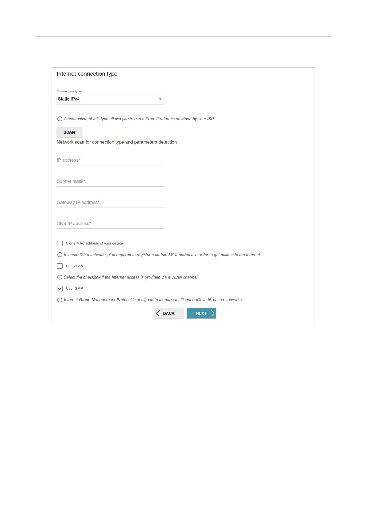
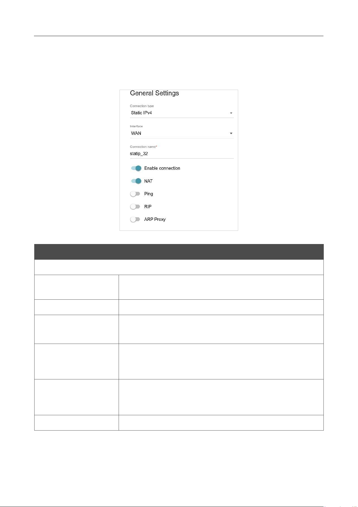
Static IPv4 Connection
Figure 43. The page for configuring Static IPv4 WAN connection.
Fill in the following fields: IP address, Subnet mask, Gateway IP address, and DNS IP
address.
DIR-842V2 AC1200 Wi-Fi Gigabit Router
User Manual
Configuring via Web-based Interface
Page 57 of 200
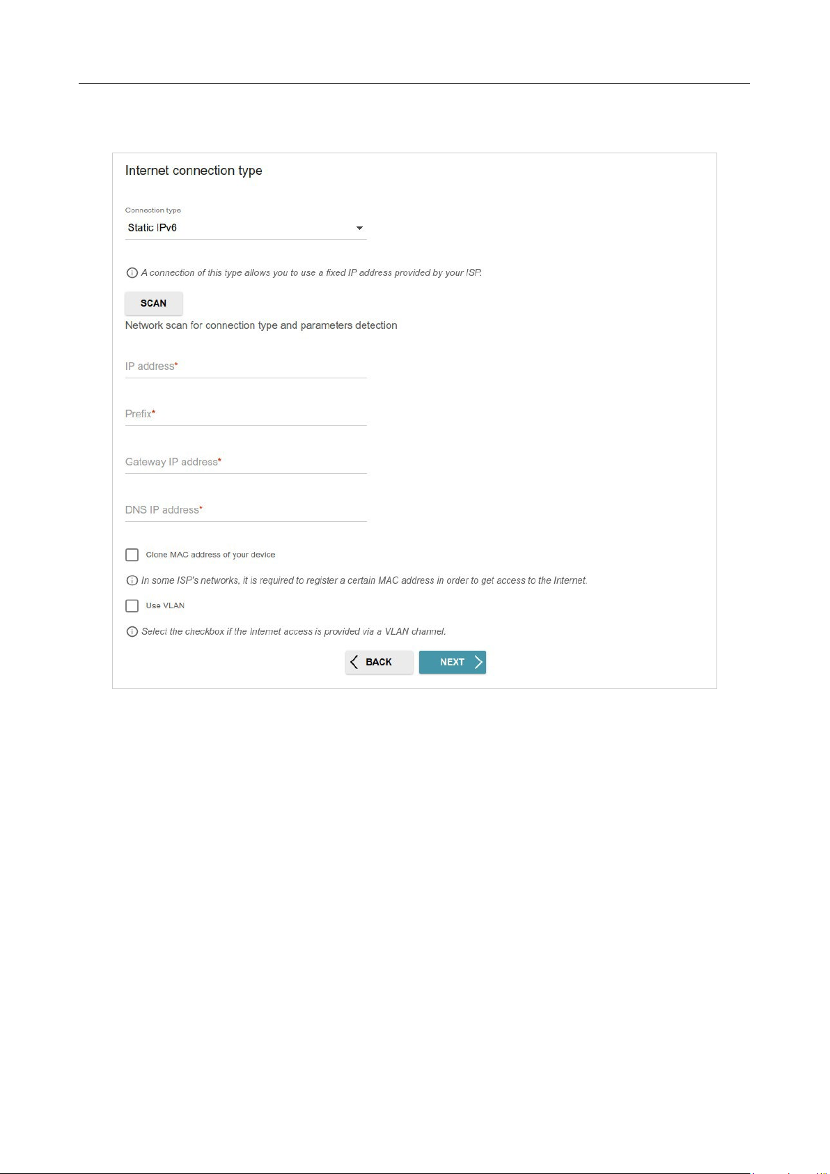
Static IPv6 Connection
Figure 44. The page for configuring Static IPv6 WAN connection.
Fill in the following fields: IP address, Prefix, Gateway IP address, and DNS IP address.
DIR-842V2 AC1200 Wi-Fi Gigabit Router
User Manual
Configuring via Web-based Interface
Page 58 of 200
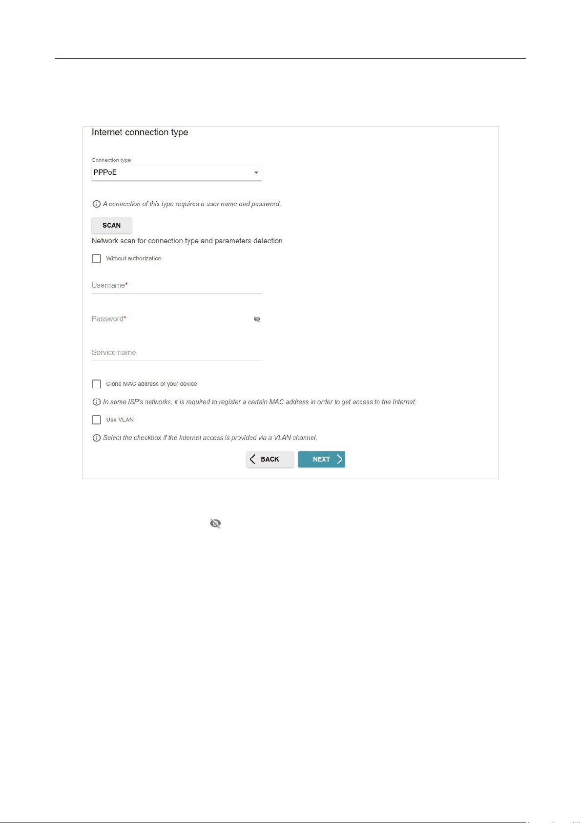
PPPoE, IPv6 PPPoE, PPPoE Dual Stack, PPPoE + Dynamic IP (PPPoE Dual
Access)
Connections
Figure 45. The page for configuring PPPoE WAN connection.
In the Username field enter the login and in the Password field enter the password provided
by
your ISP. Click the Show icon ( ) to display the entered password. If authorization is not required,
select the Without authorization checkbox.
DIR-842V2 AC1200 Wi-Fi Gigabit Router
User Manual
Configuring via Web-based Interface
Page 59 of 200
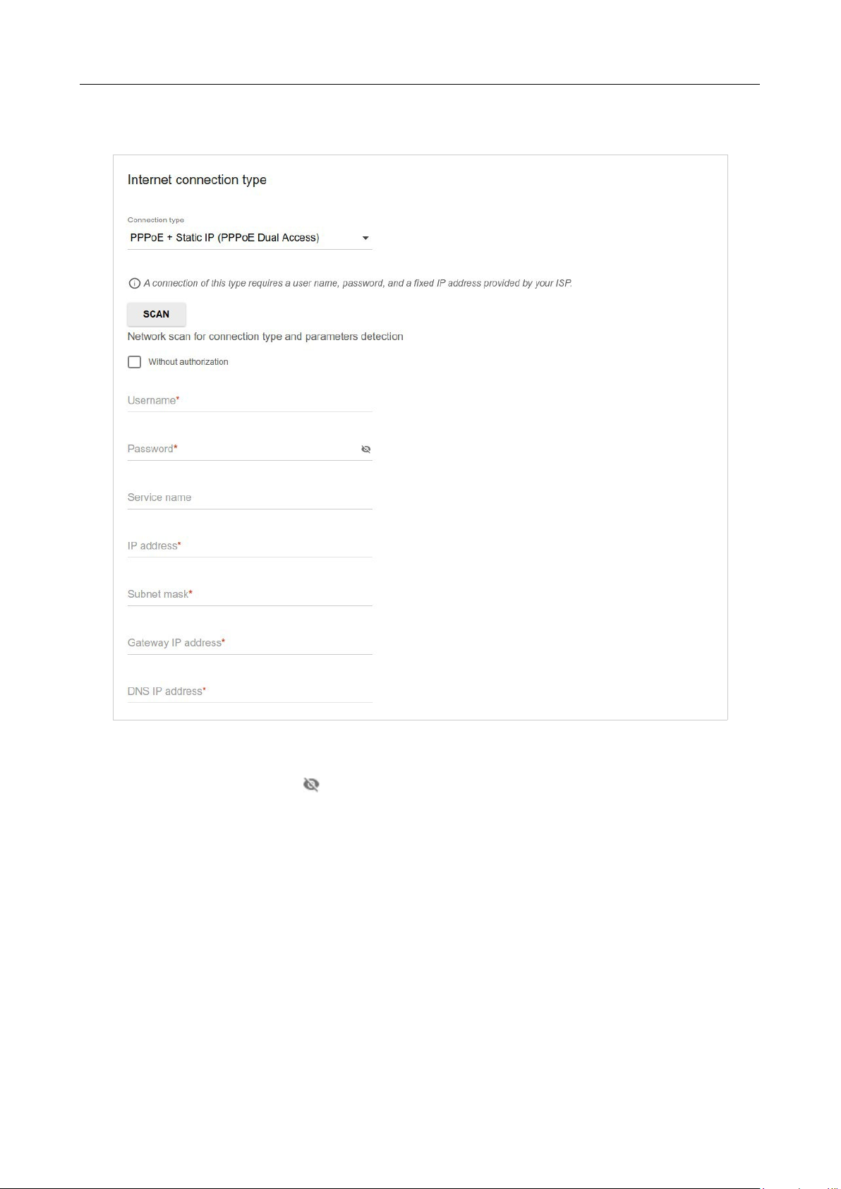
PPPoE + Static IP (PPPoE Dual Access) Connection
Figure 46. The page for configuring PPPoE + Static IP (PPPoE Dual Access) WAN connection.
In the Username field enter the login and in the Password field enter the password provided
by
your ISP. Click the Show icon ( ) to display the entered password. If authorization is not required,
select the Without authorization checkbox.
Also fill in the following fields: IP address, Subnet mask, Gateway IP address, and DNS IP
address.
DIR-842V2 AC1200 Wi-Fi Gigabit Router
User Manual
Configuring via Web-based Interface
Page 60 of 200
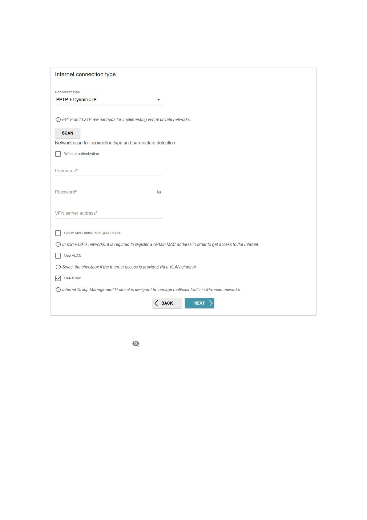
PPTP + Dynamic IP or L2TP + Dynamic IP Connection
Figure 47. The page for configuring PPTP + Dynamic IP WAN connection.
In the Username field enter the login and in the Password field enter the password provided by
your ISP. Click the Show icon ( ) to display the entered password. If authorization is not required,
select the Without authorization checkbox.
In the VPN server address field, enter the IP or URL address of the PPTP or L2TP authentication
server.
DIR-842V2 AC1200 Wi-Fi Gigabit Router
User Manual
Configuring via Web-based Interface
Page 61 of 200
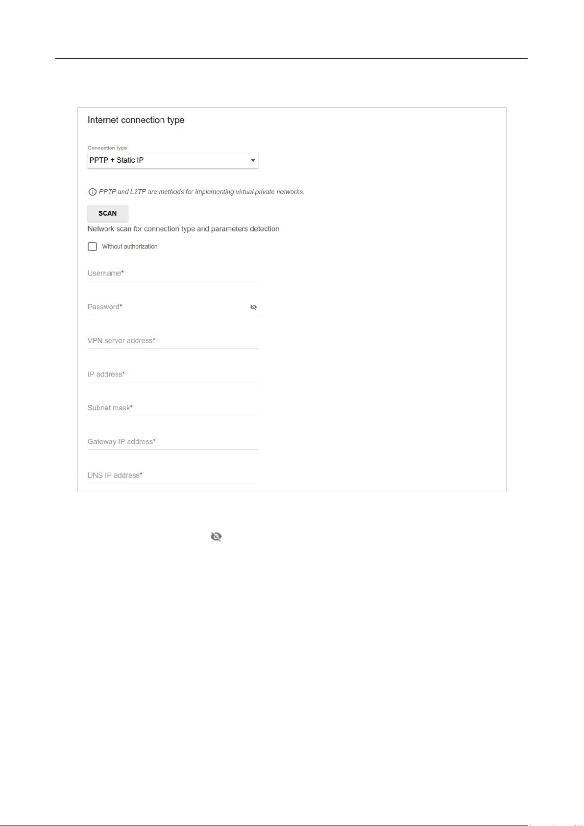
PPTP + Static IP or L2TP + Static IP Connection
Figure 48. The page for configuring PPTP + Static IP WAN connection.
In the Username field enter the login and in the Password field enter the password provided by
your ISP. Click the Show icon ( ) to display the entered password. If authorization is not required,
select the Without authorization checkbox.
In the VPN server address field, enter the IP or URL address of the PPTP or L2TP authentication
server.
Also fill in the following fields: IP address, Subnet mask, Gateway IP address, and DNS IP
address.
DIR-842V2 AC1200 Wi-Fi Gigabit Router
User Manual
Configuring via Web-based Interface
Page 62 of 200
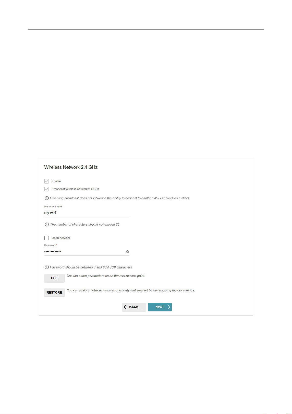
Configuring Wireless Network
This configuration step is available for the Router, Access point, WISP Repeater, and
Repeater modes.
1. On the Wireless Network 2.4 GHz page, in the Network name field, specify your own
name for the wireless network in the 2.4GHz band or leave the value suggested by the router.
2. In the Password field, specify your own password for access to the wireless network or
leave the value suggested by the router (WPS PIN of the device, see the barcode label).
3. If the router is used as a Wi-Fi client, you can specify the same parameters of the wireless
network as specified for the network to which you are connecting. To do this, click the USE
button (available for the WISP Repeater and Repeater modes only).
4. You can restore the parameters of the wireless network specified before resetting to factory
defaults. To do this, click the RESTORE button.
Figure 49. The page for configuring the wireless network.
DIR-842V2 AC1200 Wi-Fi Gigabit Router
User Manual
Configuring via Web-based Interface
Page 63 of 200
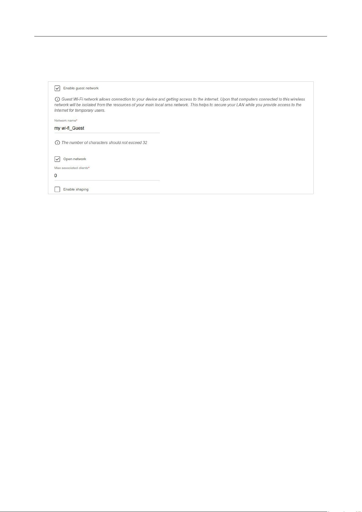
5. If you want to create an additional wireless network isolated from your LAN in the 2.4GHz
band, select the Enable guest network checkbox (available for the Router and WISP
Repeater modes only).
Figure 50. The page for configuring the wireless network.
6. In the Network name field, specify your own name for the guest wireless network or leave
the value suggested by the router.
7. If you want to create a password for access to the guest wireless network, deselect the Open
network checkbox and fill in the Password field.
8. If you want to limit the bandwidth of the guest wireless network, select the Enable
shaping checkbox and fill in the Shaping field.
9. Click the NEXT button to continue or click the BACK button to specify other settings.
10. On the Wireless Network 5 GHz page, specify needed settings for the wireless network
in the 5GHz band and click the NEXT button.
DIR-842V2 AC1200 Wi-Fi Gigabit Router
User Manual
Configuring via Web-based Interface
Page 64 of 200
C
o
n
f
i
gu
r
i
n
g
LA
N
Po
r
t
s
f
o
r
I
P
TV
/
Vo
I
P
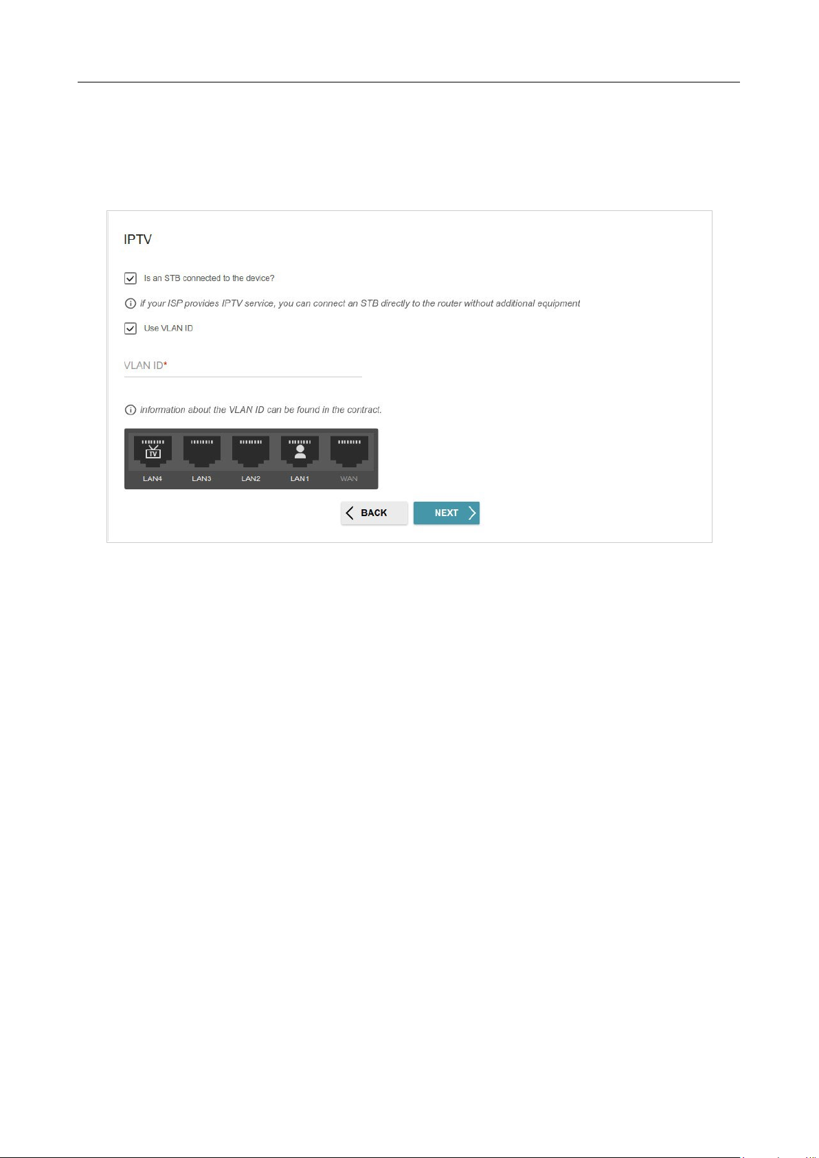
This configuration step is available for the Router mode.
1.
On the IPTV page, select the Is an STB connected to the device checkbox.
Figure 51. The page for selecting a LAN port to connect an IPTV set-top box.
2.
Select a free LAN port for connecting your set-top box.
3.
If the IPTV service is provided via a VLAN channel, select the Use VLAN ID checkbox
and fill in the VLAN ID field.
4.
Click the NEXT button to continue or click the BACK button to specify other settings.
DIR-842V2 AC1200 Wi-Fi Gigabit Router
User Manual
Configuring via Web-based Interface
Page 65 of 200
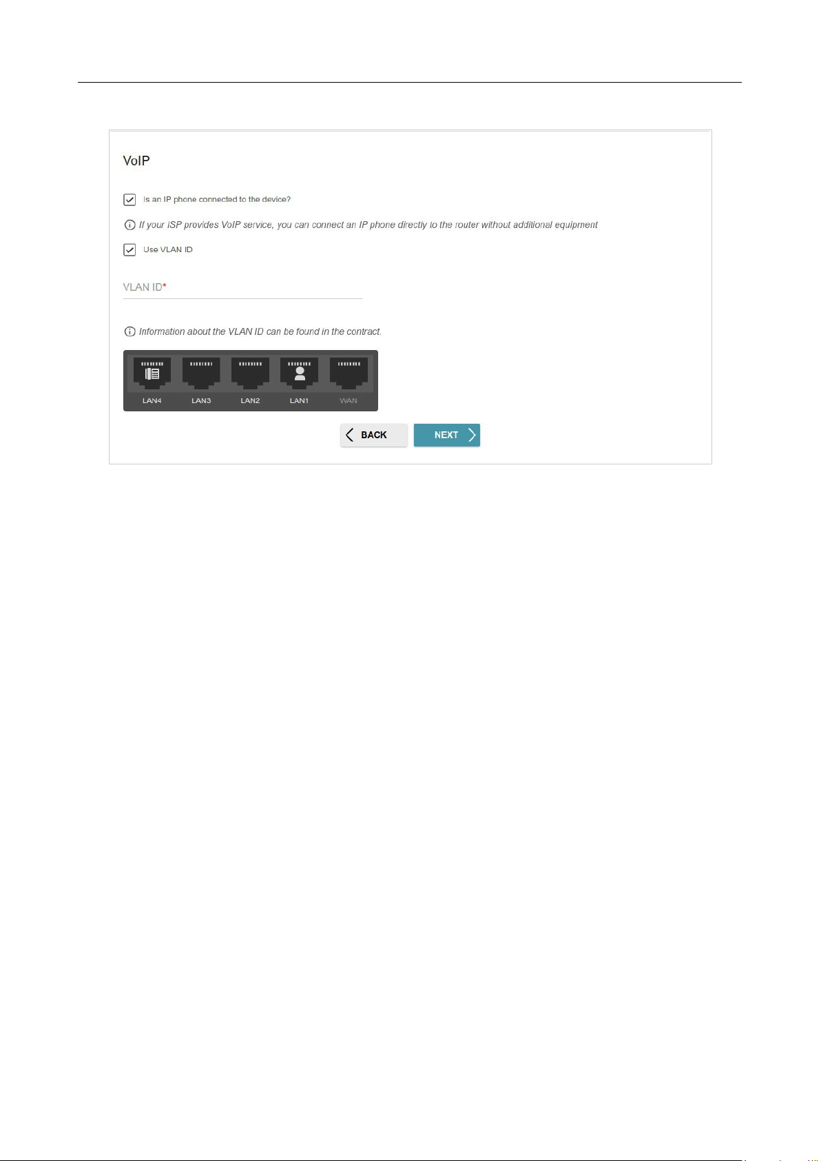
5. On the VoIP page, select the Is an IP phone connected to the device checkbox.
Figure 52. The page for selecting a LAN port to connect an VoIP phone.
6.
Select a free LAN port for connecting your IP phone.
7.
If the VoIP service is provided via a VLAN channel, select the Use VLAN ID checkbox and
fill in the VLAN ID field.
8.
Click the NEXT button to continue or click the BACK button to specify other settings.
DIR-842V2 AC1200 Wi-Fi Gigabit Router
User Manual
Configuring via Web-based Interface
Page 66 of 200
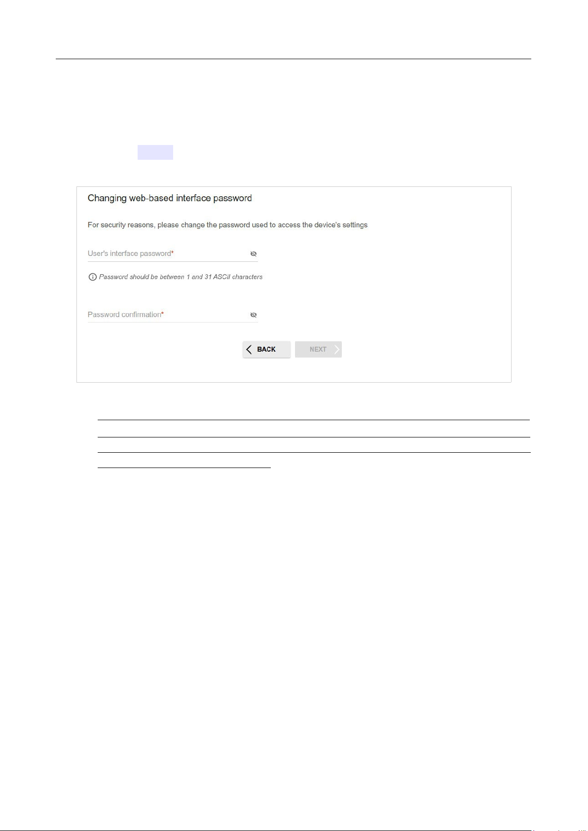
Changing Web-based Interface Password
On this page, you should change the default administrator password. To do this, enter a new password
in the User’s interface password and Password confirmation fields. You may set any
password except admin. Use digits, Latin letters (uppercase and/or lowercase), and other characters
available in the US keyboard layout.3
Figure 53. The page for changing the web-based interface password.
!
Remember or write down the new password for the administrator account. In case of losing
the new password, you can access the settings of the router only after restoring the factory
default settings via the hardware RESET button. This procedure wipes out all settings that
you have configured for your router.
Click the NEXT button to continue or click the BACK button to return to the previous page.
On the next page, check all specified settings.
Also you can save a text file with parameters set by the Wizard to your PC. To do this, click the
SAVE CONFIGURATION FILE button and follow the dialog box appeared.
To finish the Wizard, click the APPLY button. The router will apply settings and reboot. Click the
BACK button to specify other settings.

DIR-842V2 AC1200 Wi-Fi Gigabit Router
User Manual
Configuring via Web-based Interface
Page 67 of 200
3 0-9, A-Z, a-z, space, !"#$%&'()*+,-./:;<=>?@[\]^_`{|}~.

DIR-842V2 AC1200 Wi-Fi Gigabit Router
User Manual
Configuring via Web-based Interface
Page 68 of 200
If the Wizard has configured a WAN connection, after clicking the APPLY button, the page for
checking the Internet availability opens.
Figure 54. Checking the Internet availability.
If problems appeared when connecting to the Internet, click the CHECK AGAIN button to recheck
the state of the WAN connection.
If problems of connection have not been solved, contact the technical support of your ISP (as a rule,
the technical support phone is provided with the agreement) or the D-Link technical support.
To specify other settings, click the ADVANCED SETTINGS button. After clicking the
ADVANCED SETTINGS button, the Home page opens (see the Home Page section, page 38).
DIR-842V2 AC1200 Wi-Fi Gigabit Router
User Manual
Configuring via Web-based Interface
Page 69 of 200
Settings / Internet
WAN
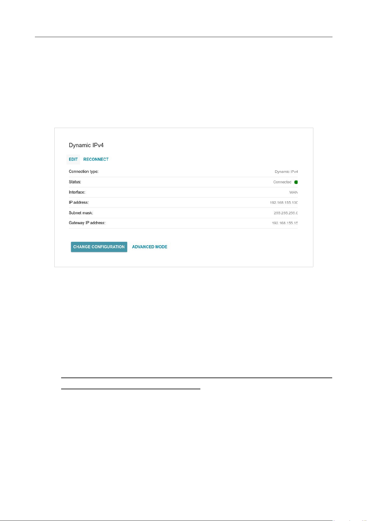
On the Settings / Internet / WAN page, you can create and edit connections used by the router.
By default, a Dynamic IPv4 connection is configured in the system. It is assigned to the WAN
port of the router.
Figure 55. The Settings / Internet / WAN page. The simplified mode.
To edit an existing connection, click the EDIT button. Change the needed parameters and click the
APPLY button.
To disconnect a connection and establish it again, click the RECONNECT button.
To remove an existing connection and create a new one, click the CHANGE CONFIGURATION
button. Upon that the connection creation page opens.
To create several WAN connections, go to the advanced mode. To do this, click the ADVANCED
MODE button.
!
When connections of some types are created, the Settings / Internet / WAN page is
automatically displayed in the advanced mode.
DIR-842V2 AC1200 Wi-Fi Gigabit Router
User Manual
Configuring via Web-based Interface
Page 70 of 200
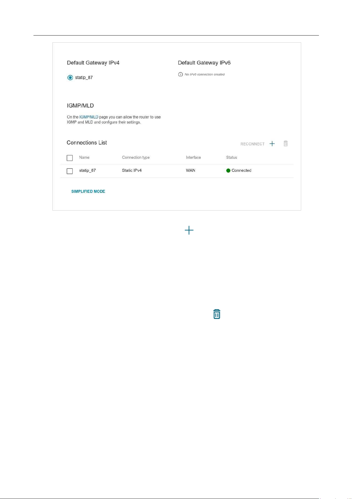
Figure 56. The Settings / Internet / WAN page. The advanced mode.
To create a new connection, click the ADD button ( ) in the Connections List section. Upon
that the connection creation page opens.
To edit an existing connection, in the Connections List section, left-click the relevant line in the
table. Change the needed parameters and click the APPLY button.
To disconnect a connection and establish it again, select the checkbox located to the left of the
relevant line in the table and click the RECONNECT button.
To remove a connection, in the Connections List section, select the checkbox located to the left
of the relevant line in the table and click the DELETE button ( ).
To allow multicast traffic (e.g. streaming video) for a connection, click the IGMP/MLD link (for the
description of the page, see the IGMP/MLD section, page 163).
To use one of existing WAN connections as the default IPv4 or IPv6 connection, in the Default
Gateway section, select the choice of the radio button which corresponds to this connection.
To return to the simplified mode, click the SIMPLIFIED MODE button (the button is unavailable if
several WAN connections are created).
DIR-842V2 AC1200 Wi-Fi Gigabit Router
User Manual
Configuring via Web-based Interface
Page 71 of 200
Creating Dynamic IPv4 or Static IPv4 WAN Connection
On the connection creation page, in the General Settings section, select the relevant value from
the Connection type drop-down list and specify the needed values.
Figure 57. The page for creating a new Static IPv4 connection. The General Settings section.
Parameter Description
General Settings
Interface
A physical or virtual WAN interface to which the new connection
will be assigned.
Connection name
A name for the connection for easier identification.
Enable connection
Move the switch to the right to enable the connection.
Move the switch to the left to disable the connection.
NAT
If the switch is moved to the right, the network address translation
function is enabled. Do not disable the function unless your ISP
requires this.
Ping
If the switch is moved to the right, the router responds to ping
requests from the external network through this connection. For
security reasons, it is recommended to disable this function.
RIP
Move the switch to the right to allow using RIP for this connection.

DIR-842V2 AC1200 Wi-Fi Gigabit Router
User Manual
Configuring via Web-based Interface
Page 72 of 200
Figure 58. The page for creating a new Static IPv4 connection. The Ethernet section.
Parameter Description
Ethernet
MAC address
A MAC address assigned to the interface. This parameter is
mandatory if your ISP uses MAC address binding. In the field, enter
the MAC address registered by your ISP upon concluding the
agreement.
To set the MAC address of the network interface card (of the
computer that is being used to configure the router at the moment)
as the MAC address of the WAN interface, move the Clone MAC
address of your NIC switch to the right. When the switch is moved
to the right, the field is unavailable for editing.
To set the router's MAC address, click the RESTORE DEFAULT
MAC ADDRESS button (the button is available when the switch is
moved to the right).
MTU
The maximum size of units transmitted by the interface.
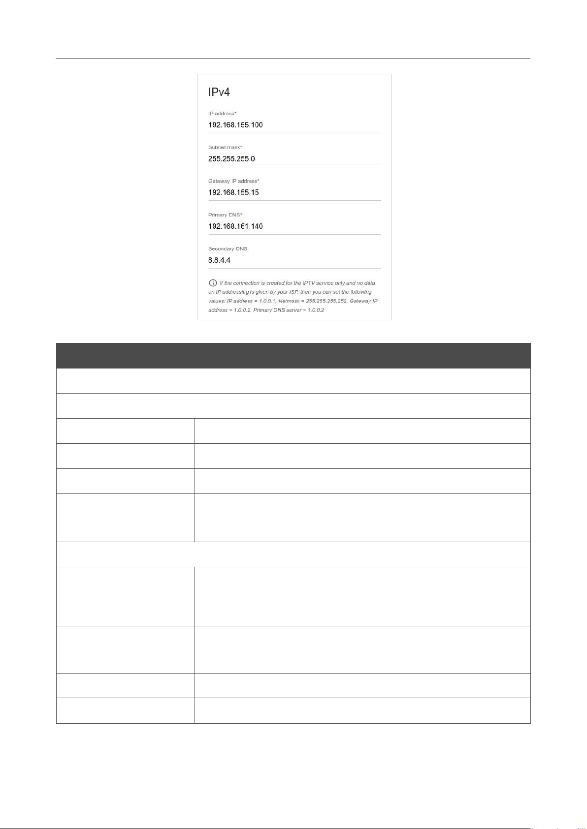
DIR-842V2 AC1200 Wi-Fi Gigabit Router
User Manual
Configuring via Web-based Interface
Page 73 of 200
Figure 59. The page for creating a new Static IPv4 connection. The IPv4 section.
Parameter Description
IPv4
For Static IPv4 type
IP address
Enter an IP address for this WAN connection.
Subnet mask
Enter a subnet mask for this WAN connection.
Gateway IP address
Enter an IP address of the gateway used by this WAN connection.
Primary DNS/
Secondary DNS
Enter addresses of the primary and secondary DNS servers in the
relevant fields.
For Dynamic IPv4 type
Obtain DNS server
addresses
automatically
Move the switch to the right to configure automatic assignment of
DNS server addresses. Upon that the Primary DNS and
Secondary DNS fields are not available for editing.
Primary DNS/
Secondary DNS
Enter addresses of the primary and secondary DNS servers in the
relevant fields.
Vendor ID
The identifier of your ISP. Optional.
Hostname
A name of the router specified by your ISP. Optional.
When all needed settings are configured, click the APPLY button.

DIR-842V2 AC1200 Wi-Fi Gigabit Router
User Manual
Configuring via Web-based Interface
Page 74 of 200
Creating Dynamic IPv6 or Static IPv6 WAN Connection
On the connection creation page, in the General Settings section, select the relevant value from
the Connection type drop-down list and specify the needed values.
Figure 60. The page for creating a new Static IPv6 connection. The General Settings section.
Parameter Description
General Settings
Interface
A physical or virtual WAN interface to which the new connection
will be assigned.
Connection name
A name for the connection for easier identification.
Enable connection
Move the switch to the right to enable the connection.
Move the switch to the left to disable the connection.
Ping
If the switch is moved to the right, the router responds to ping
requests from the external network through this connection. For
security reasons, it is recommended to disable this function.
RIPng
Move the switch to the right to allow using RIPng for this
connection.

DIR-842V2 AC1200 Wi-Fi Gigabit Router
User Manual
Configuring via Web-based Interface
Page 75 of 200
Figure 61. The page for creating a new Static IPv6 connection. The Ethernet section.
Parameter
Description
Ethernet
MAC address
A MAC address assigned to the interface. This parameter is
mandatory if your ISP uses MAC address binding. In the field, enter
the MAC address registered by your ISP upon concluding the
agreement.
To set the MAC address of the network interface card (of the
computer that is being used to configure the router at the moment)
as the MAC address of the WAN interface, move the Clone MAC
address of your NIC switch to the right. When the switch is moved
to the right, the field is unavailable for editing.
To set the router's MAC address, click the RESTORE DEFAULT
MAC ADDRESS button (the button is available when the switch is
moved to the right).
MTU
The maximum size of units transmitted by the interface.
Figure 62. The page for creating a new Static IPv6 connection. The IPv6 section.

DIR-842V2 AC1200 Wi-Fi Gigabit Router
User Manual
Configuring via Web-based Interface
Page 76 of 200
Parameter Description
IPv6
For Static IPv6 type
IPv6 address
Enter an IPv6 address for this WAN connection.
Prefix
The length of the subnet prefix. The value 64 is used usually.
Gateway IPv6 address
Enter an IPv6 address of the gateway used by this WAN connection.
Primary IPv6 DNS
server/Secondary IPv6
DNS server
Enter addresses of the primary and secondary IPv6 DNS servers in
the relevant fields.
For Dynamic IPv6 type
Get IPv6
Select a method for IPv6 address assignment from the drop-down
list or leave the Automatically value.
Enable prefix
delegation
Move the switch to the right if it is necessary that the router requests
a prefix to configure IPv6 addresses for the local network from a
delegating router.
Obtain DNS server
addresses
automatically
Move the switch to the right to configure automatic assignment of
IPv6 DNS server addresses. Upon that the Primary IPv6 DNS
server and Secondary IPv6 DNS server fields are not available
for editing.
Primary IPv6 DNS
server/Secondary IPv6
DNS server
Enter addresses of the primary and secondary IPv6 DNS servers in
the relevant fields.
When all needed settings are configured, click the APPLY button.
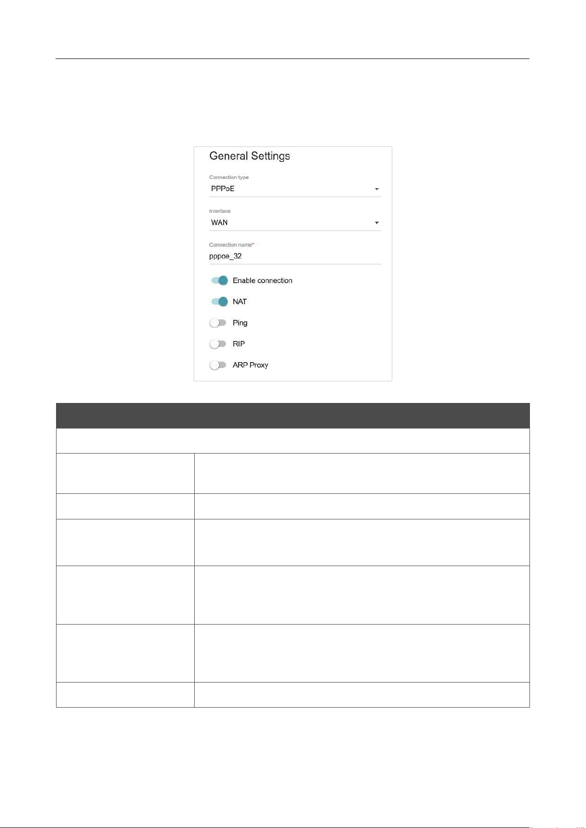
DIR-842V2 AC1200 Wi-Fi Gigabit Router
User Manual
Configuring via Web-based Interface
Page 77 of 200
Creating PPPoE WAN Connection
On the connection creation page, in the General Settings section, select the relevant value from
the Connection type drop-down list and specify the needed values.
Figure 63. The page for creating a new PPPoE connection. The General Settings section.
Parameter Description
General Settings
Interface
A physical or virtual WAN interface to which the new connection
will be assigned.
Connection name
A name for the connection for easier identification.
Enable connection
Move the switch to the right to enable the connection.
Move the switch to the left to disable the connection.
NAT
If the switch is moved to the right, the network address translation
function is enabled. Do not disable the function unless your ISP
requires this.
Ping
If the switch is moved to the right, the router responds to ping
requests from the external network through this connection. For
security reasons, it is recommended to disable this function.
RIP
Move the switch to the right to allow using RIP for this connection.

DIR-842V2 AC1200 Wi-Fi Gigabit Router
User Manual
Configuring via Web-based Interface
Page 78 of 200
Figure 64. The page for creating a new PPPoE connection. The Ethernet section.
Parameter Description
Ethernet
MAC address
A MAC address assigned to the interface. This parameter is
mandatory if your ISP uses MAC address binding. In the field, enter
the MAC address registered by your ISP upon concluding the
agreement.
To set the MAC address of the network interface card (of the
computer that is being used to configure the router at the moment)
as the MAC address of the WAN interface, move the Clone MAC
address of your NIC switch to the right. When the switch is moved
to the right, the field is unavailable for editing.
To set the router's MAC address, click the RESTORE DEFAULT
MAC ADDRESS button (the button is available when the switch is
moved to the right).
MTU
The maximum size of units transmitted by the interface.

DIR-842V2 AC1200 Wi-Fi Gigabit Router
User Manual
Configuring via Web-based Interface
Page 79 of 200
Figure 65. The page for creating a new PPPoE connection. The PPP section.
Parameter Description
PPP
Without authorization
Move the switch to the right if you don't need to enter a username
and password to access the Internet.
Username
A username (login) to access the Internet.
Password
A password to access the Internet.
Click the Show icon ( ) to
display the entered password.
Service name
The name of the PPPoE authentication server.

DIR-842V2 AC1200 Wi-Fi Gigabit Router
User Manual
Configuring via Web-based Interface
Page 80 of 200
Parameter Description
MTU
The maximum size of units transmitted by the interface.
Encryption protocol
Select a method of MPPE encryption.
• No encryption: MPPE encryption is not applied.
• MPPE 40 128 bit: MPPE encryption with a 40-bit or 128-bit
key is applied.
• MPPE 40 bit: MPPE encryption with a 40-bit key is applied.
• MPPE 128 bit: MPPE encryption with a 128-bit key is
applied.
MPPE encryption can be applied only if the MS-CHAP or MS-
CHAPV2 value is selected from the Authentication protocol
drop-down list.
Authentication
protocol
Select a required authentication method from the drop-down list or
leave the AUTO value.
Keep Alive
Move the switch to the right if you want the router to
keep you
connected to your ISP even when the connection has been inactive
for a specified period of time. If the switch is moved to the right, the
LCP interval and LCP fails fields are available. Specify the
required values.
Dial on demand
Move the switch to the right if you want the router to establish
connection to the Internet on demand. In the Maximum idle time
field, specify a period of inactivity (in seconds) after which the
connection should be terminated.
Extra options
Advanced options of the pppd daemon which need to be specified
for this connection. Optional.
Static IP address
Fill in the field if you want to use a static IP address to access the
Internet.
PPP debug
Move the switch to the right if you want to log
all data on PPP
connection debugging.
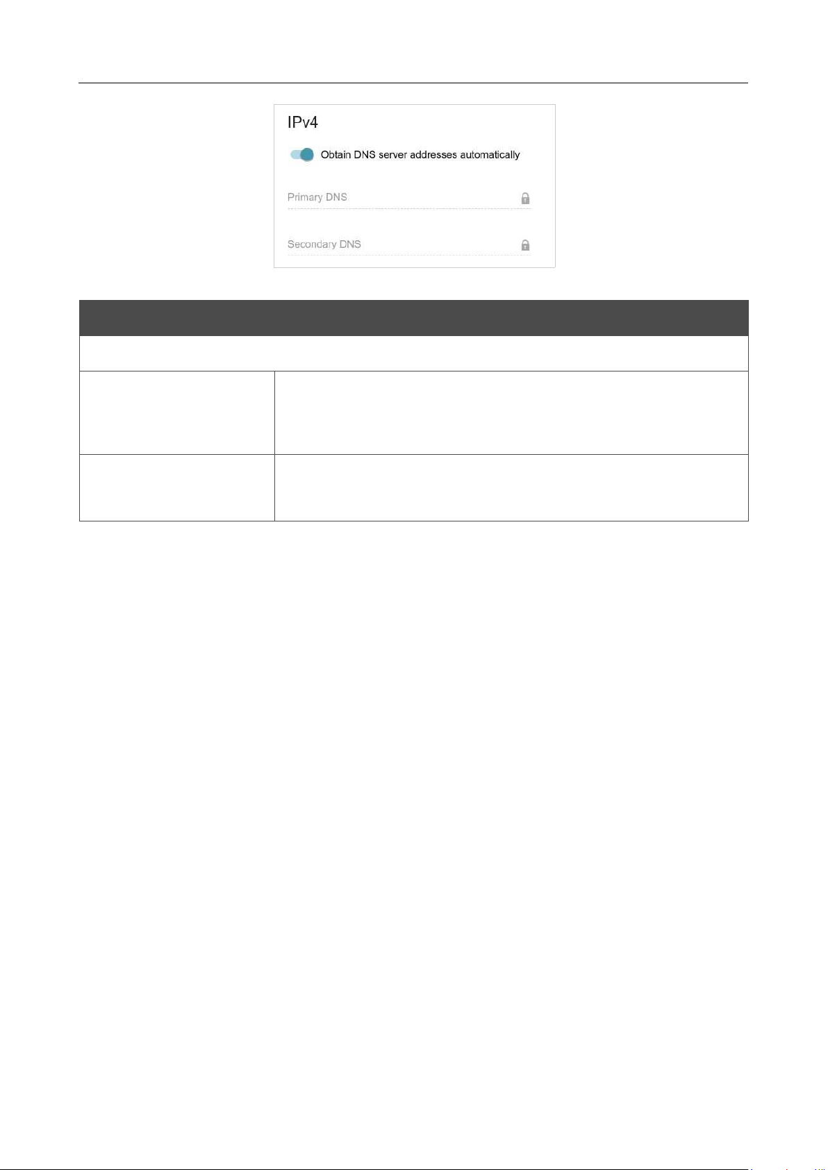
DIR-842V2 AC1200 Wi-Fi Gigabit Router
User Manual
Configuring via Web-based Interface
Page 81 of 200
Figure 66. The page for creating a new PPPoE connection. The IPv4 section.
Parameter Description
IPv4
Obtain DNS server
addresses
automatically
Move the switch to the right to configure automatic assignment of
DNS server addresses. Upon that the Primary DNS and
Secondary DNS fields are not available for editing.
Primary DNS/
Secondary DNS
Enter addresses of the primary and secondary DNS servers in the
relevant fields.
When all needed settings are configured, click the APPLY button. In the simplified mode, after
clicking the button, the window for creating an additional connection opens.
If your ISP offers access to local services (e.g. audio and video resources), click the CREATE
CONNECTION button. On the page displayed, specify the parameters for the connection of the
Dynamic IPv4 or Static IPv4 type and click the APPLY button.
If you do not need to create an additional connection, click the SKIP button. In this case, the
Settings / Internet / WAN page opens.
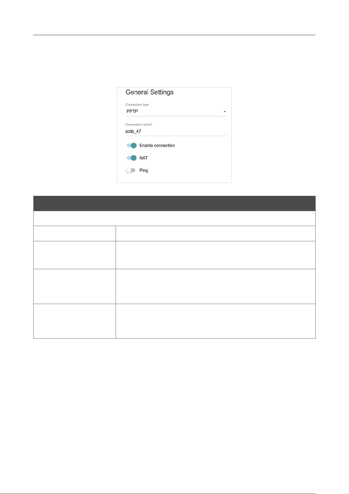
DIR-842V2 AC1200 Wi-Fi Gigabit Router
User Manual
Configuring via Web-based Interface
Page 82 of 200
Creating PPTP, L2TP, or L2TP over IPsec WAN Connection
On the connection creation page, in the General Settings section, select the relevant value from
the Connection type drop-down list and specify the needed values.
Figure 67. The page for creating a new PPTP connection. The General Settings section.
Parameter Description
General Settings
Connection name
A name for the connection for easier identification.
Enable connection
Move the switch to the right to enable the connection.
Move the switch to the left to disable the connection.
NAT
If the switch is moved to the right, the network address translation
function is enabled. Do not disable the function unless your ISP
requires this.
Ping
If the switch is moved to the right, the router responds to ping
requests from the external network through this connection. For
security reasons, it is recommended to disable this function.

DIR-842V2 AC1200 Wi-Fi Gigabit Router
User Manual
Configuring via Web-based Interface
Page 83 of 200
Figure 68. The page for creating a new PPTP connection. The PPP section.
Parameter Description
PPP
Without authorization
Move the switch to the right if you don't need to enter a username
and password to access the Internet.
Username
A username (login) to access the Internet.
Password
A password to access the Internet.
Click the Show icon ( ) to
display the entered password.
VPN server address
The IP or URL address of the PPTP or L2TP authentication server.

DIR-842V2 AC1200 Wi-Fi Gigabit Router
User Manual
Configuring via Web-based Interface
Page 84 of 200
Parameter Description
MTU
The maximum size of units transmitted by the interface.
Encryption protocol
Select a method of MPPE encryption.
• No encryption: MPPE encryption is not applied.
• MPPE 40/128 bit: MPPE encryption with a 40-bit or 128-
bit key is applied.
• MPPE 40 bit: MPPE encryption with a 40-bit key is applied.
• MPPE 128 bit: MPPE encryption with a 128-bit key is
applied.
MPPE encryption can be applied only if the MS-CHAP, MS-
CHAPV2, or AUTO value is selected from the Authentication
protocol drop-down list.
Authentication protocol
Select a required authentication method from the drop-down list or
leave the AUTO value.
Keep Alive
Move the switch to the right if you want the router to
keep you
connected to your ISP even when the connection has been inactive
for a specified period of time. If the switch is moved to the right, the
LCP interval and LCP fails fields are available. Specify the
required values.
Dial on demand
Move the switch to the right if you want the router to establish
connection to the Internet on demand. In the Maximum idle time
field, specify a period of inactivity (in seconds) after which the
connection should be terminated.
Extra options
Advanced options of the pppd daemon which need to be specified
for this connection. Optional.
Static IP address
Fill in the field if you want to use a static IP address to access the
Internet.
PPP debug
Move the switch to the right if you want to log
all data on PPP
connection debugging.
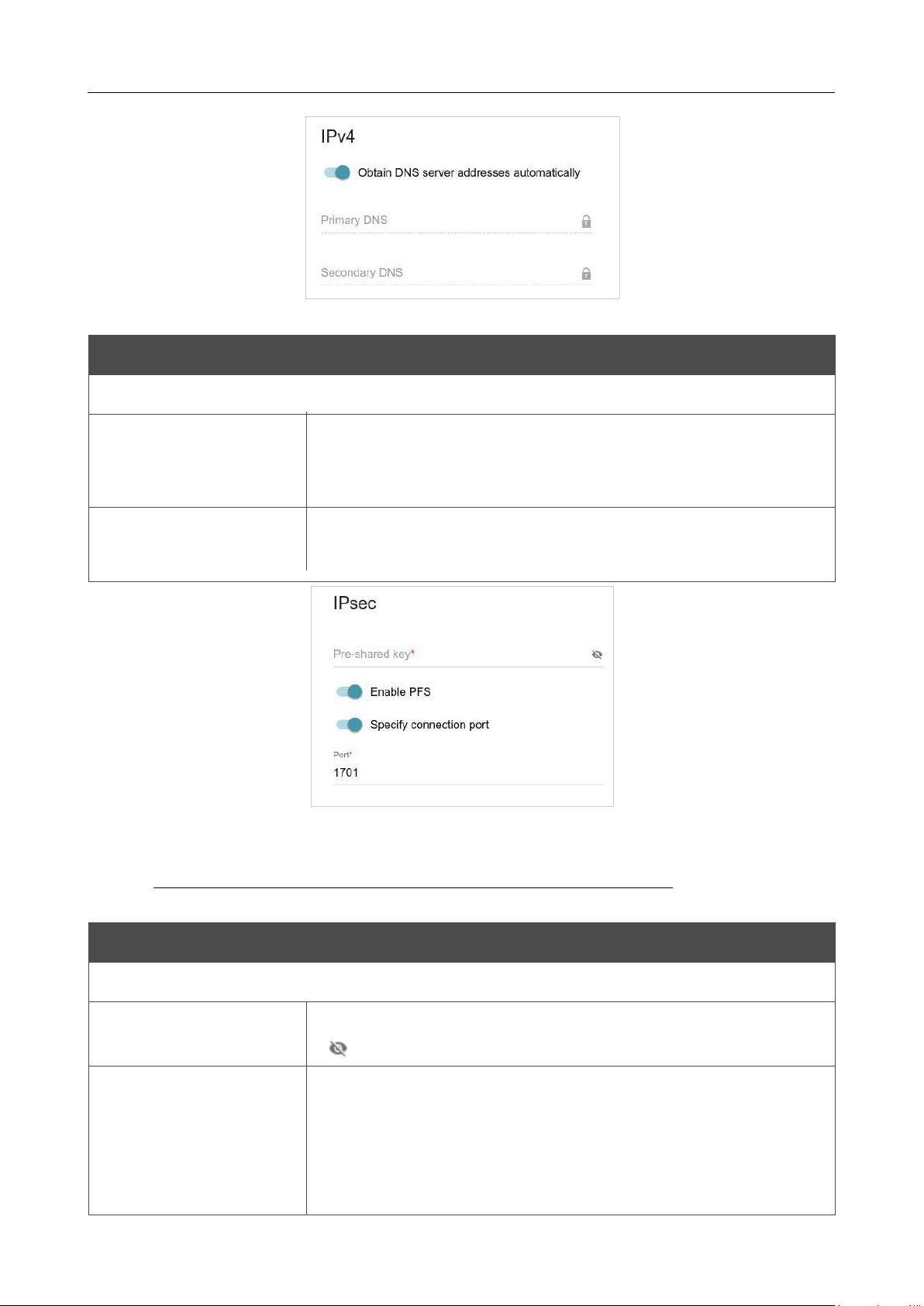
DIR-842V2 AC1200 Wi-Fi Gigabit Router
User Manual
Configuring via Web-based Interface
Page 85 of 200
Figure 69. The page for creating a new PPTP connection. The IPv4 section.
Parameter
Description
IPv4
Obtain DNS server
addresses
automatically
Move the switch to the right to configure automatic assignment of
DNS server addresses. Upon that the Primary DNS and
Secondary DNS fields are not available for editing.
Primary DNS/
Secondary DNS
Enter addresses of the primary and secondary DNS servers in the
relevant fields.
Figure 70. The page for creating a new L2TP over IPsec connection. The IPsec section.
!
Setting for both parties which establish the tunnel should be the same.
Parameter Description
IPsec (for the L2TP over IPsec type)
Pre-shared key
A key for mutual authentication of the parties.
Click the Show icon
( ) to display the entered key.
Enable PFS
Move the switch to the right to enable the PFS option (Perfect
Forward Secrecy). If the switch is moved to the right, a new
encryption key exchange will be used upon establishing the IPsec
tunnel. This option enhances the security level of data transfer, but
increases the load on DIR-842V2.

DIR-842V2 AC1200 Wi-Fi Gigabit Router
User Manual
Configuring via Web-based Interface
Page 86 of 200
Parameter Description
Specify connection
port
Move the switch to the right to change the port used for data
exchange
with the other party enter the needed value in the Port filed displayed.
By default, the value
1701
is specified.
When all needed settings are configured, click the APPLY button.
After clicking the button, the window for additional configuration of the connection opens.
If you want to use this WAN connection to access the Internet, select the to the Internet choice of
the radio button. Then select the existing connection which will be used to access the PPTP/L2TP
server or click the CREATE CONNECTION button.
If you have already configured the connection to the Internet and you want to use this WAN
connection only to connect to the virtual private network, select the to the virtual private network
choice of the radio button.
Click the CONTINUE button.
After creating a connection of the L2TP over IPsec type, on the Functions / Advanced / IPsec
page, in the Status section, the current state of the IPsec tunnel is displayed.
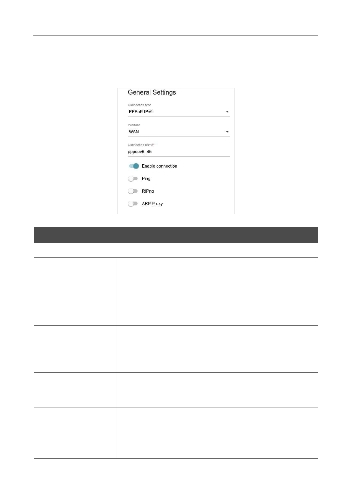
DIR-842V2 AC1200 Wi-Fi Gigabit Router
User Manual
Configuring via Web-based Interface
Page 87 of 200
Creating PPPoE IPv6 or PPPoE Dual Stack WAN Connection
On the connection creation page, in the General Settings section, select the relevant value from
the Connection type drop-down list and specify the needed values.
Figure 71. The page for creating a new PPPoE IPv6 connection. The General Settings section.
Parameter Description
General Settings
Interface
A physical or virtual WAN interface to which the new connection
will be assigned.
Connection name
A name for the connection for easier identification.
Enable connection
Move the switch to the right to enable the connection.
Move the switch to the left to disable the connection.
NAT
For the PPPoE Dual Stack type only.
If the switch is moved to the right, the network address translation
function is enabled. Do not disable the function unless your ISP
requires this.
Ping
If the switch is moved to the right, the router responds to ping
requests from the external network through this connection. For
security reasons, it is recommended to disable this function.
RIP
For the PPPoE Dual Stack type only.
Move the switch to the right to allow using RIP for this connection.
RIPng
Move the switch to the right to allow using RIPng for this
connection.
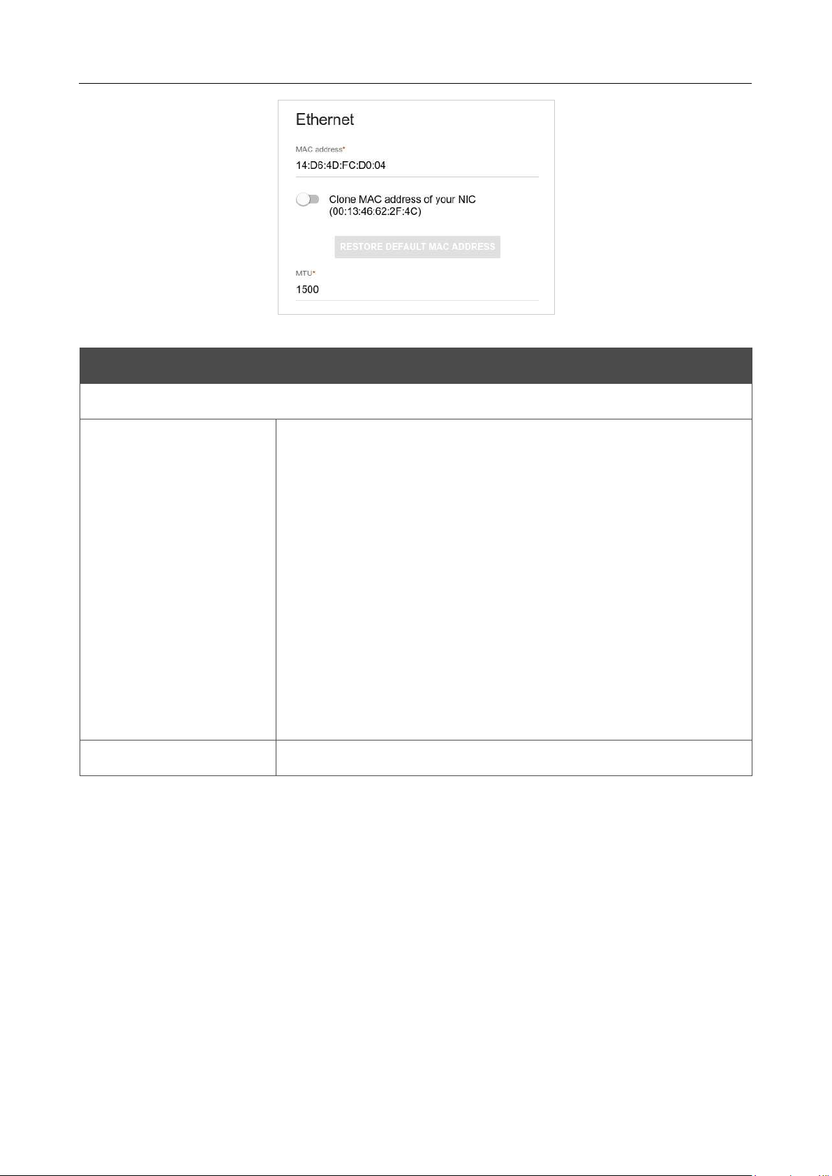
DIR-842V2 AC1200 Wi-Fi Gigabit Router
User Manual
Configuring via Web-based Interface
Page 88 of 200
Figure 72. The page for creating a new PPPoE IPv6 connection. The Ethernet section.
Parameter Description
Ethernet
MAC address
A MAC address assigned to the interface. This parameter is
mandatory if your ISP uses MAC address binding. In the field, enter
the MAC address registered by your ISP upon concluding the
agreement.
To set the MAC address of the network interface card (of the
computer that is being used to configure the router at the moment)
as the MAC address of the WAN interface, move the Clone MAC
address of your NIC switch to the right. When the switch is moved
to the right, the field is unavailable for editing.
To set the router's MAC address, click the RESTORE DEFAULT
MAC ADDRESS button (the button is available when the switch is
moved to the right).
MTU
The maximum size of units transmitted by the interface.
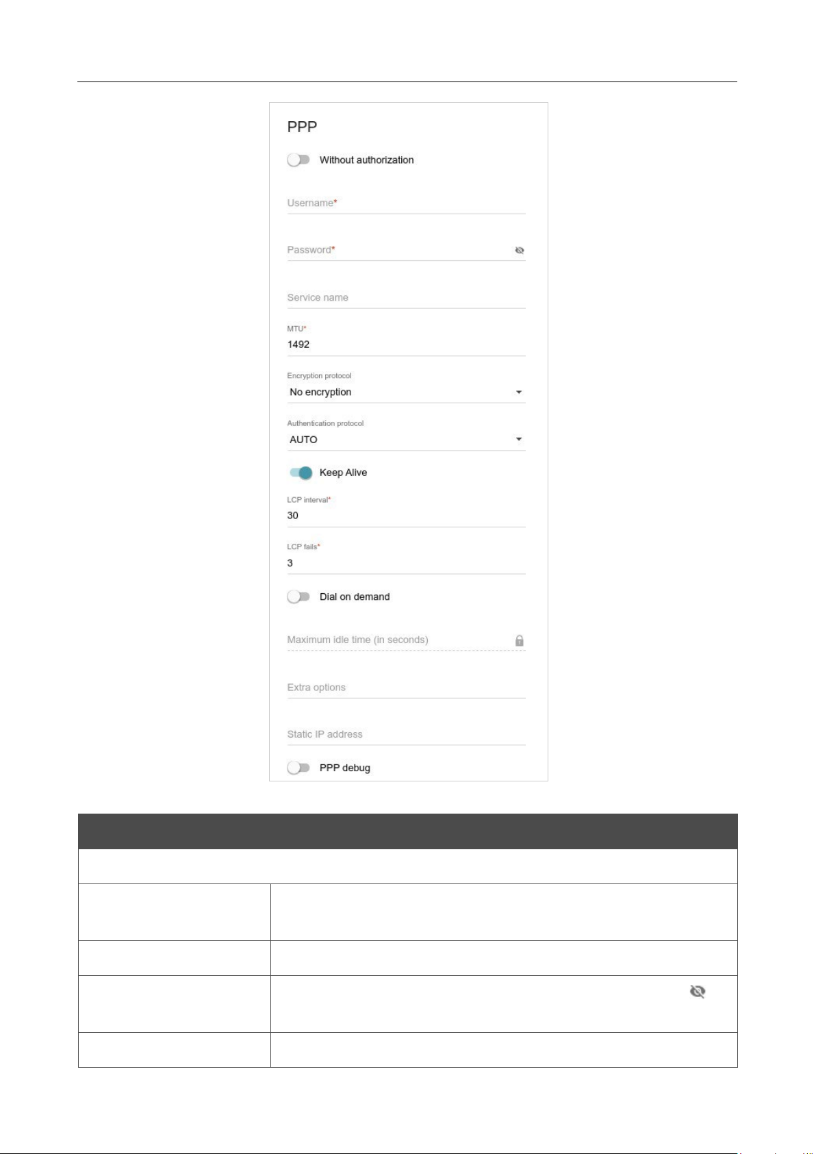
DIR-842V2 AC1200 Wi-Fi Gigabit Router
User Manual
Configuring via Web-based Interface
Page 89 of 200
Figure 73. The page for creating a new PPPoE IPv6 connection. The PPP section.
Parameter Description
PPP
Without authorization
Move the switch to the right if you don't need to enter a username
and password to access the Internet.
Username
A username (login) to access the Internet.
Password
A password to access the Internet.
Click the Show icon ( ) to
display the entered password.
Service name
The name of the PPPoE authentication server.

DIR-842V2 AC1200 Wi-Fi Gigabit Router
User Manual
Configuring via Web-based Interface
Page 90 of 200
Parameter Description
MTU
The maximum size of units transmitted by the interface.
Encryption protocol
Select a method of MPPE encryption.
• No encryption: MPPE encryption is not applied.
• MPPE 40/128 bit: MPPE encryption with a 40-bit or 128-bit
key is applied.
• MPPE 40 bit: MPPE encryption with a 40-bit key is applied.
• MPPE 128 bit: MPPE encryption with a 128-bit key is
applied.
MPPE encryption can be applied only if the MS-CHAP, MS-
CHAPV2, or AUTO value is selected from the Authentication
protocol drop-down list.
Authentication
protocol
Select a required authentication method from the drop-down list or
leave the AUTO value.
Keep Alive
Move the switch to the right if you want the router to
keep you
connected to your ISP even when the connection has been inactive
for a specified period of time. If the switch is moved to the right, the
LCP interval and LCP fails fields are available. Specify the
required values.
Dial on demand
Move the switch to the right if you want the router to establish
connection to the Internet on demand. In the Maximum idle time
field, specify a period of inactivity (in seconds) after which the
connection should be terminated.
Extra options
Advanced options of the pppd daemon which need to be specified
for this connection. Optional.
Static IP address
Fill in the field if you want to use a static IP address to access the
Internet.
PPP debug
Move the switch to the right if you want to log
all data on PPP
connection debugging.
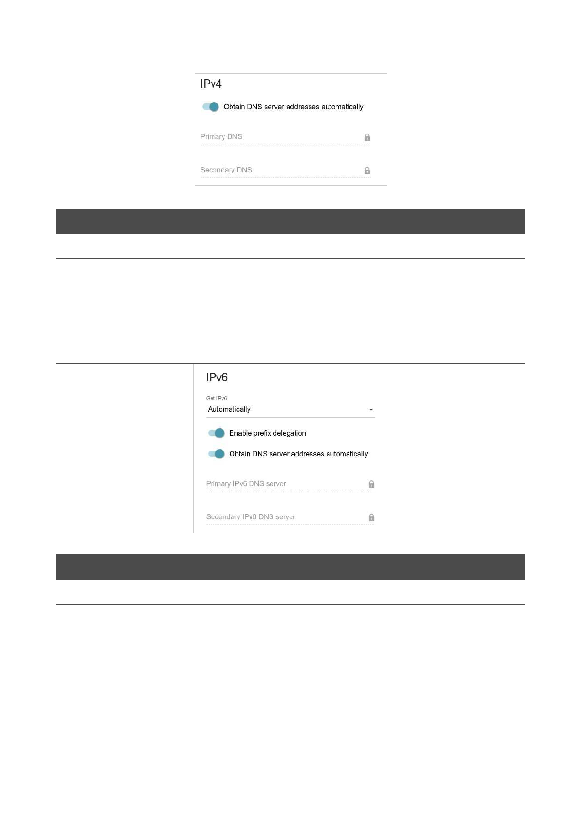
DIR-842V2 AC1200 Wi-Fi Gigabit Router
User Manual
Configuring via Web-based Interface
Page 91 of 200
Figure 74. The page for creating a new
PPPoE Pv6 connection. The IPv4 section.
Parameter Description
IPv4 (for the PPPoE Dual Stack type)
Obtain DNS server
addresses
automatically
Move the switch to the right to configure automatic assignment of
DNS server addresses. Upon that the Primary DNS and
Secondary DNS fields are not available for editing.
Primary DNS/
Secondary DNS
Enter addresses of the primary and secondary DNS servers in the
relevant fields.
Figure 75. The page for creating a new PPPoE Pv6 connection. The IP section.
Parameter Description
IPv6
Get IPv6
Select a method for IPv6 address assignment from the drop-down
list or leave the Automatically value.
Enable prefix
delegation
Move the switch to the right if it is necessary that the router requests
a prefix to configure IPv6 addresses for the local network from a
delegating router.
Obtain DNS server
addresses
automatically
Move the switch to the right to configure automatic assignment of
IPv6 DNS server addresses. Upon that the Primary IPv6 DNS
server and Secondary IPv6 DNS server fields are not available
for editing.

DIR-842V2 AC1200 Wi-Fi Gigabit Router
User Manual
Configuring via Web-based Interface
Page 92 of 200
Parameter Description
Primary IPv6 DNS
server/Secondary IPv6
DNS server
Enter addresses of the primary and secondary IPv6 DNS servers in
the relevant fields.
When all needed settings are configured, click the APPLY button.
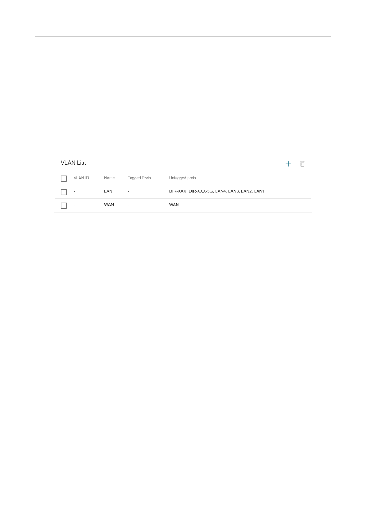
DIR-842V2 AC1200 Wi-Fi Gigabit Router
User Manual
Configuring via Web-based Interface
Page 93 of 200
VLAN
On the Settings / Internet / VLAN page, you can edit existing and create new virtual networks
(VLAN), e.g., for distinguishing traffic or specifying additional WAN interfaces.
By default, 2 VLANs are created in the router's system:
• LAN: For the LAN interface, it includes LAN ports and Wi-Fi networks. You cannot delete
this VLAN.
• WAN: For the WAN interface; it includes the INTERNET port. You can edit or delete this
VLAN.
Figure 76. The Settings / Internet / VLAN page.
In order to add untagged LAN ports or available Wi-Fi networks to an existing or new VLAN, first
you need to exclude them from the LAN network on this page. To do this, select the LAN line. On
the opened page, from the Type drop-down list of the element corresponding to the relevant LAN
port or Wi-Fi network, select the Excluded value and click the APPLY button.
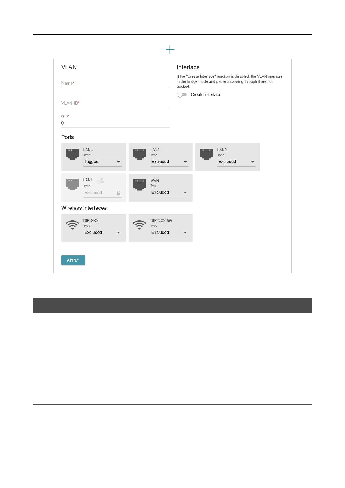
DIR-842V2 AC1200 Wi-Fi Gigabit Router
User Manual
Configuring via Web-based Interface
Page 94 of 200
To create a new VLAN, click the ADD button ( ).
Figure 77. The page for adding a VLAN.
You can specify the following parameters:
Parameter Description
Name
A name for the VLAN for easier identification.
VLAN ID
An identifier of the VLAN.
QoS
A priority tag for the transmitted traffic.
Create interface
Move the switch to the right to create an interface that can be used
for creating WAN connections.
Move the switch to the left for the VLAN to work in the bridge
mode. This mode is mostly used to connect IPTV set-top boxes.

DIR-842V2 AC1200 Wi-Fi Gigabit Router
User Manual
Configuring via Web-based Interface
Page 95 of 200
Parameter Description
Ports
Select a type for each port included in the VLAN.
• Untagged: Untagged traffic will be transmitted through the
specified port.
• Tagged: Tagged traffic will be transmitted through the
specified port. If at least one port of this type is included to
the VLAN, it is required to fill in the VLAN ID and QoS
fields.
Leave the Excluded value for the ports not included in the VLAN.
Wireless interfaces
Select the Untagged value for each Wi-Fi interface included in the
Leave the Excluded value for the Wi-Fi interfaces not included in
the VLAN.
Click the APPLY button.
To edit an existing VLAN, select the relevant line in the table. On the page displayed, change the
parameters and click the APPLY button.
To remove an existing VLAN, select the checkbox located to the left of the relevant line in the table
and click the DELETE button ( ).
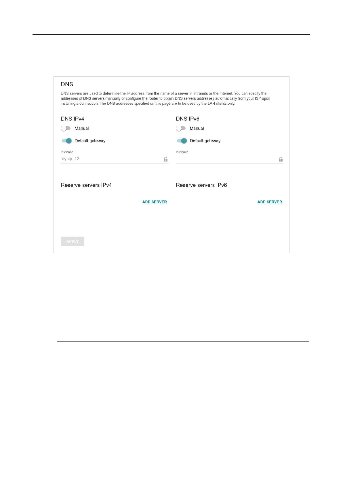
DIR-842V2 AC1200 Wi-Fi Gigabit Router
User Manual
Configuring via Web-based Interface
Page 96 of 200
DNS
On the Settings / Internet / DNS page, you can add DNS servers to the system.
Figure 78. The Settings / Internet / DNS page.
DNS servers are used to determine the IP address from the name of a server in Intranets or the Internet
(as a rule, they are specified by an ISP or assigned by a network administrator).
You can specify the addresses of DNS servers manually on this page or configure the router to obtain
DNS servers addresses automatically from your ISP upon installing a connection. Also here you can
specify addresses of reserve DNS servers which the router can use if the addresses specified manually
or obtained automatically are unavailable.
!
When you use the built-in DHCP server, the network parameters (including DNS servers)
are distributed to clients automatically.

DIR-842V2 AC1200 Wi-Fi Gigabit Router
User Manual
Configuring via Web-based Interface
Page 97 of 200
Specify needed settings for IPv4 in the DNS IPv4 section and for IPv6 in the DNS IPv6 section.
If you want to configure automatic obtainment of DNS servers addresses, move the Manual switch
to the left. Then move the Default gateway switch to the left and from the Interface drop-down
list select a WAN connection which will be used to obtain addresses of DNS servers automatically.
If you want the router to use the default WAN connection to obtain addresses of DNS servers, move
the Default gateway switch to the right.
To specify a DNS server manually, move the Manual switch to the right. In the Name Servers
section of the relevant IP version, click the ADD SERVER button, and in the line displayed, enter
an IP address of the DNS server.
To specify a reserve DNS server, in the Reserve servers section of the relevant IP version, click
the ADD SERVER button, and in the line displayed, enter an IP address of the DNS server.
To remove a DNS server from the page, click the Delete icon ( ) in the line of the address.
When all needed settings are configured, click the APPLY button.
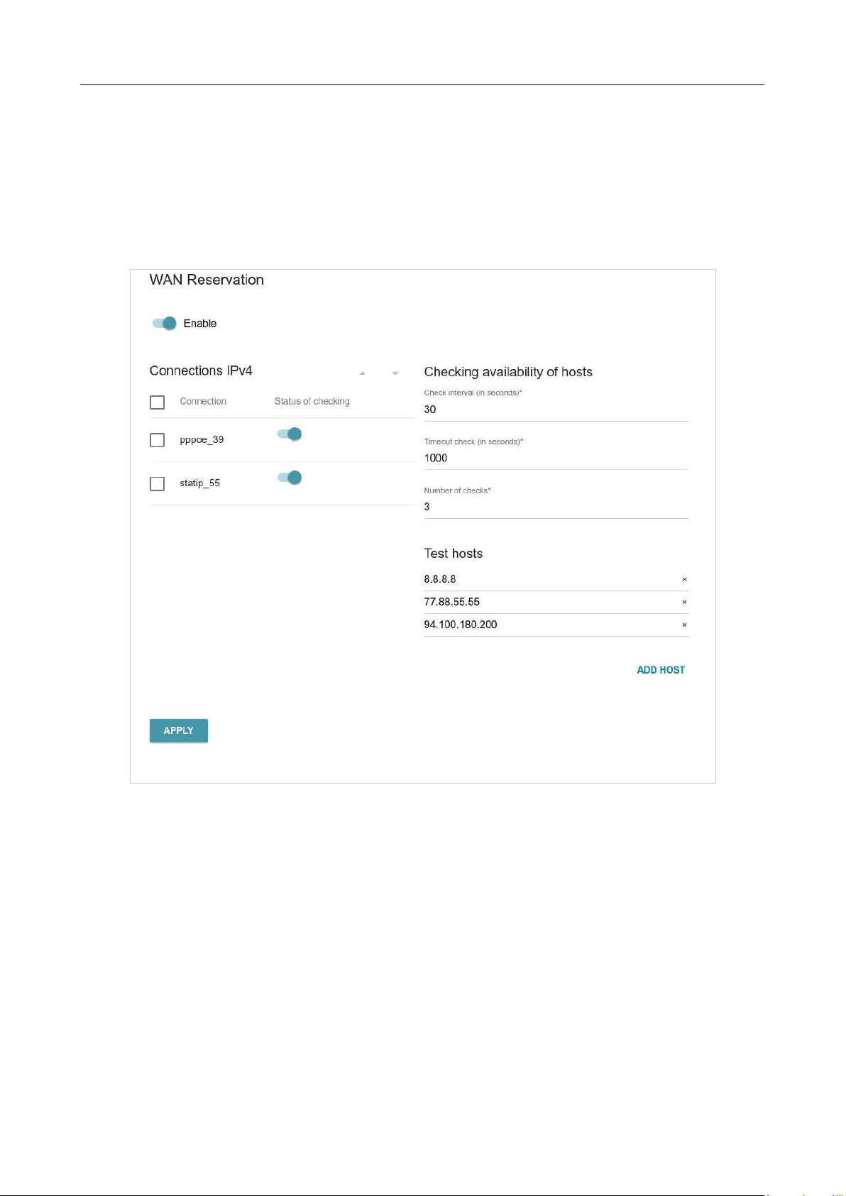
DIR-842V2 AC1200 Wi-Fi Gigabit Router
User Manual
Configuring via Web-based Interface
Page 98 of 200
Settings / WAN Failover
On the Settings / WAN Failover page, you can enable the WAN backup function, which provides
you with uninterrupted access to the Internet. When your main connection breaks down, the router
activates the backup connection; and when the main channel is recovered, the router switches to it
and disconnects the reserve one.
Figure 79. The Settings / WAN Failover page.

DIR-842V2 AC1200 Wi-Fi Gigabit Router
User Manual
Configuring via Web-based Interface
Page 99 of 200
To activate the backup function, create several WAN connections. After that go to the Settings /
WAN Failover page, move the Enable switch to the right, and specify the needed values in the
fields displayed on the page.
Parameter Description
Connections IPv4
Connection
Sort the existing IPv4 connections
in order of priority. The first
connection on the list serves as the main connection, the others are
backup connections.
In order to move a connection in the table, select the checkbox in the
line of the connection and use the Up ( ) and Down ( ) buttons.
Status of checking
Move the switch to the right to let the router use ICMP ping
mechanism for checking the connection.
Move the switch to the left to let the router check only the status of
the connection (may be useful for unstable connections).
Checking availability of hosts
Check interval
A time period (in seconds) between regular checks of the hosts’
availability. By default, the value 30 is specified.
The value of this
field should not be higher than product of Timeout check and
Number of checks fields values.
Several ping requests are sent to check the hosts. After a successful
attempt the router keeps using the main connection. After several
failed attempts the next connection from the list is enabled.
Timeout check
A time period (in seconds) allocated for a respond to one ping
request.
Number of checks
A number of failed attempts to check the health of a connection after
which the next connection from the list is enabled.
Test hosts
IP addresses that the router will check for availability via ICMP ping
mechanism.
Click the ADD HOST button, and in the line displayed, enter an IP
address or leave values suggested by the router.
To remove an IP address from the list, click the Delete icon ( ) in
the line of the address.
When all needed settings are configured, click the APPLY button.
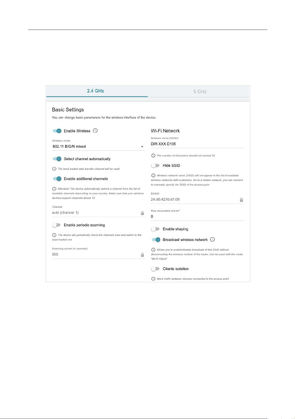
DIR-842V2 AC1200 Wi-Fi Gigabit Router
User Manual
Configuring via Web-based Interface
Page 100 of
Settings / Wireless network
On the Settings / Wireless network page, you can change basic parameters for the wireless
interface of the router and configure the basic and additional wireless networks. To configure the
2.4GHz band or 5GHz band, go to the relevant tab.
Figure 80. Basic settings of the wireless LAN.

DIR-842V2 AC1200 Wi-Fi Gigabit Router
User Manual
Configuring via Web-based Interface
Page 101 of
In the Basic Settings section, the following parameters are available:
Parameter Description
Enable Wireless
To enable Wi-Fi connection, move the switch to the right.
To disable Wi-Fi connection, move the switch to the left.
To enable/disable Wi-Fi connection on a schedule, click the Set
schedule button ( ). In the opened window, you can create a
new schedule (see the Schedule section, page 181) or use the
existing one. Existing schedules are displayed in the
Interval of
execution drop-down list in the simplified mode.
To enable Wi-Fi connection at the time specified in the schedule
and disable it at the other time, select the Enable wireless
connection value from the Action drop-down list and click the
SAVE button.
To disable Wi-Fi connection at the time specified in the schedule
and enable it at the other time, select the Disable wireless
connection value from the Action drop-down list and click the
SAVE button.
To change or delete the schedule, click the Edit schedule
button ( )
. In the opened window, change the parameters and
click the SAVE button or click the DELETE FROM
SCHEDULE button.
Wireless mode
Operating mode of the wireless network of the router. This
parameter defines standards of the devices that will be able to use
your wireless network. Select a value from the drop-down list.
Select channel
automatically
Move the switch to the right to let the router itself choose the
channel with the least interference.
Enable additional
channels
If the switch is moved to the left, the device automatically selects
one of available standard channels. To use additional channels
(the
12th and 13th – in the 2.4 GHz band, the 100th and higher – in the
5 GHz band), move the switch to the right.
Channel
The wireless channel number. Left-click to open the window for
selecting a channel (the action is available, when the
Select
channel automatically switch is moved to the left).
Enable periodic
scanning
Move the switch to the right to let the router search for a free
channel in certain periods of time. When the switch is moved to
the right, the Scanning period field is available for editing.

DIR-842V2 AC1200 Wi-Fi Gigabit Router
User Manual
Configuring via Web-based Interface
Page 102 of
Scanning period
Specify a period of time (in seconds) after which the router
rescans channels.
When you have configured the parameters, click the APPLY button.
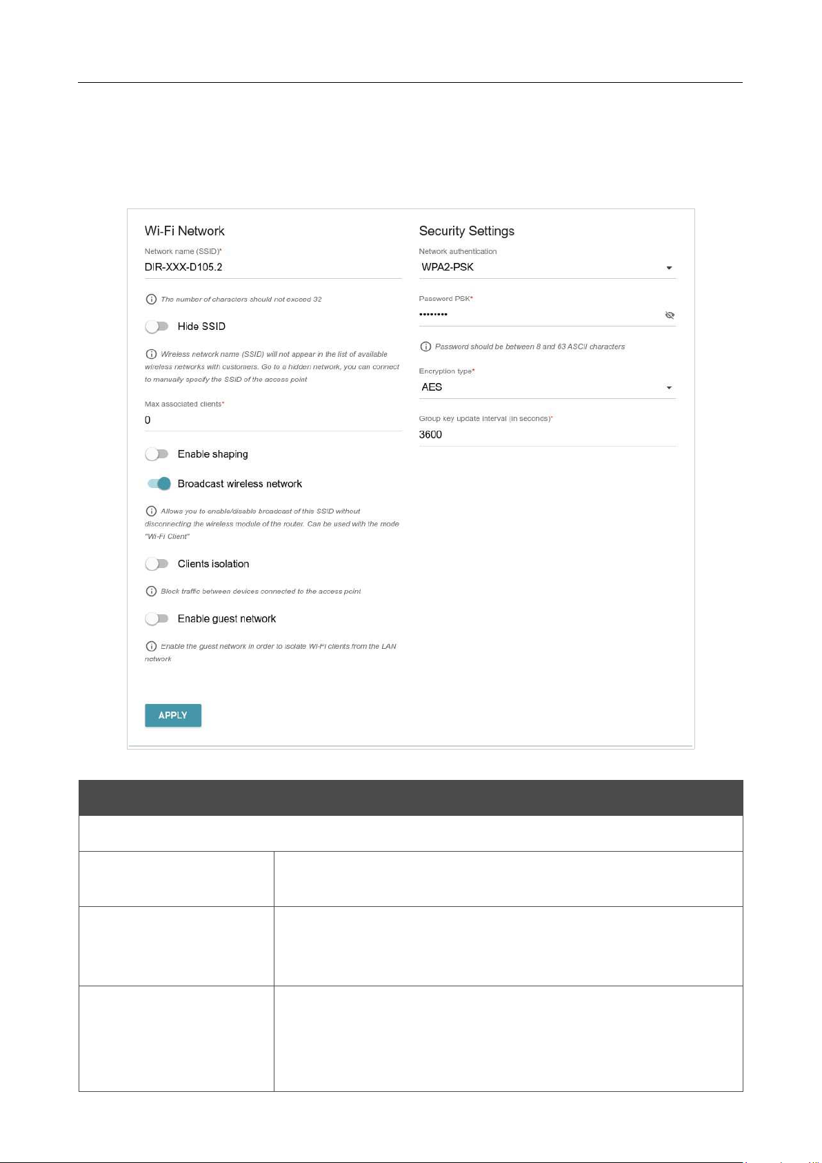
DIR-842V2 AC1200 Wi-Fi Gigabit Router
User Manual
Configuring via Web-based Interface
Page 103 of
To edit the settings of the basic wireless network, in the Wi-Fi Network section, change the needed
parameters and click the APPLY button.
Also you can create an additional wireless network. To do this, click the ADD WI-FI NETWORK
button. On the opened page, specify the relevant parameters.
Figure 81. Creating a wireless network.
Parameter Description
Wi-Fi Network
Network name (SSID)
A name for the wireless network. The name can consist of digits and
Latin characters.
Hide SSID
If the switch is moved to the right, other users cannot see your Wi-Fi
network. It is recommended not to hide the network in order to
simplify initial configuration of the wireless network.
BSSID
The unique identifier for this wireless network. You cannot change
the value of this parameter, it is determined in the device's internal
settings. The field is displayed in the settings of the existing wireless
network.

DIR-842V2 AC1200 Wi-Fi Gigabit Router
User Manual
Configuring via Web-based Interface
Page 104 of
Parameter Description
Max associated clients
The maximum number of devices connected to the wireless network.
When the value 0 is specified, the device does not limit the number
of connected clients.
Enable shaping
Move the switch to the right to limit the maximum bandwidth of the
wireless network. In the Shaping field displayed, specify the
maximum value of speed (Mbit/s).
Move the switch to the left not to limit the maximum bandwidth.
Broadcast wireless
network
If the wireless network broadcasting is disabled, devices cannot
connect to the wireless network. Upon that DIR-842V2
can connect
to another access point as a wireless client.
To enable/disable broadcasting on a schedule, click the Set
schedule button ( ). In the opened window, you can create a new
schedule (see the Schedule section, page 181) or use the
existing one.
Existing schedules are displayed in the Interval of execution drop-
down list in the simplified mode.
To enable broadcasting at the time specified in the schedule and
disable it at the other time, select the Enable wireless network
broadcasting value from the Action drop-down list and click the
SAVE button. When the wireless connection is disabled, the device
will not be able to enable broadcasting of this wireless network on
schedule.
To disable broadcasting at the time specified in the schedule and
enable it at the other time, select the Disable wireless network
broadcasting value from the Action drop-down list and click the
SAVE button.
To change or delete the schedule, click the Edit schedule
button
( ). In the opened window, change the parameters and click the
SAVE button or click the DELETE FROM SCHEDULE button.
If you created an additional network, you can configure, change or
delete a schedule for each network. To do this, click the button in the
line of the network.
Clients isolation
Move the switch to the right to forbid wireless clients of this
wireless network to communicate to each other.

DIR-842V2 AC1200 Wi-Fi Gigabit Router
User Manual
Configuring via Web-based Interface
Page 105 of
Enable guest network
This function is available for the additional network. Move the switch
to the right if you want the devices connected to the
additional
network to be isolated from the devices and resources of the
router's
LAN.
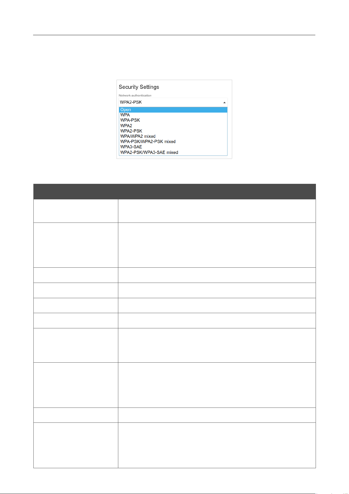
DIR-842V2 AC1200 Wi-Fi Gigabit Router
User Manual
Configuring via Web-based Interface
Page 106 of 200
In the Security Settings section, you can change security settings of the wireless network.
By default, the WPA2-PSK network authentication type of the wireless network is specified. WPS
PIN from the barcode label is used as the network key.
Figure 82. Network authentication types supported by the router.
The router supports the following authentication types:
Authentication type Description
Open
Open authentication (with WEP encryption for wireless network
modes not supporting 802.11n or 802.11ac devices).
WEP
Authentication with a shared key with WEP encryption. This
authentication type is not available when a mode supporting
802.11n
or 802.11ac devices is selected from the Wireless mode drop-
down list on the Settings / Wireless Network page.
WPA
WPA-based authentication using a RADIUS server.
WPA-PSK
WPA-based authentication using a PSK.
WPA2
WPA2-based authentication using a RADIUS server.
WPA2-PSK
WPA2-based authentication using a PSK.
WPA/WPA2 mixed
A mixed type of authentication. When this value is selected, devices
using the WPA authentication type and devices using the WPA2
authentication type can connect to the wireless network.
WPA-PSK/WPA2-PSK
mixed
A mixed type of authentication. When this value is selected, devices
using the WPA-PSK authentication type and devices using the
WPA2-PSK authentication type can connect to the wireless
network.
WPA3-SAE
WPA3-based authentication using a PSK and SAE method.
WPA2-PSK/WPA3-SAE
mixed
A mixed type of authentication. When this value is selected, devices
using the WPA2-PSK authentication type and devices using the
WPA3-SAE authentication type can connect to the wireless
network.
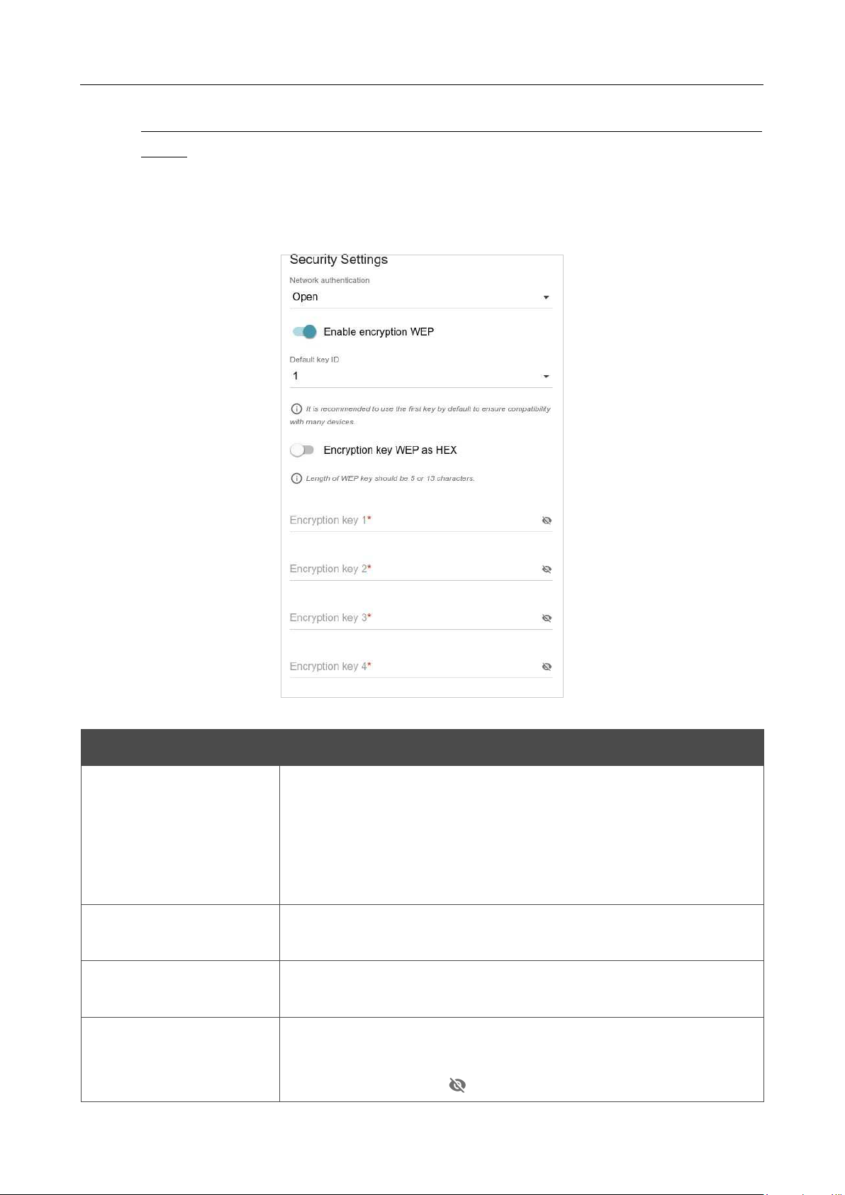
DIR-842V2 AC1200 Wi-Fi Gigabit Router
User Manual
Configuring via Web-based Interface
Page 107 of 200
!
The WPA, WPA2, and WPA/WPA2 mixed authentication types require a RADIUS
server.
When the Open or WEP value is selected, the following settings are displayed on the page
(unavailable for the wireless network operating modes which support the standard 802.11n or
802.11ac):
Figure 83. The Open value is selected from the Network authentication drop-down list.
Parameter Description
Enable encryption WEP
For Open authentication type only.
To activate WEP encryption, move the switch to the right. Upon that
the Default key ID drop-down list, the
Encryption key WEP as
HEX switch, and four Encryption key fields are displayed on the
page.
Default key ID
The number of the key (from first to fourth) which will be used for
WEP encryption.
Encryption key WEP as
HEX
Move the switch to the right to set a hexadecimal number as a key
for encryption.
Encryption key
(1-4)
Keys for WEP encryption. The router uses the key selected from the
Default key ID drop-down list. It is required to specify all the fields.
Click the Show icon ( ) to display the entered key.
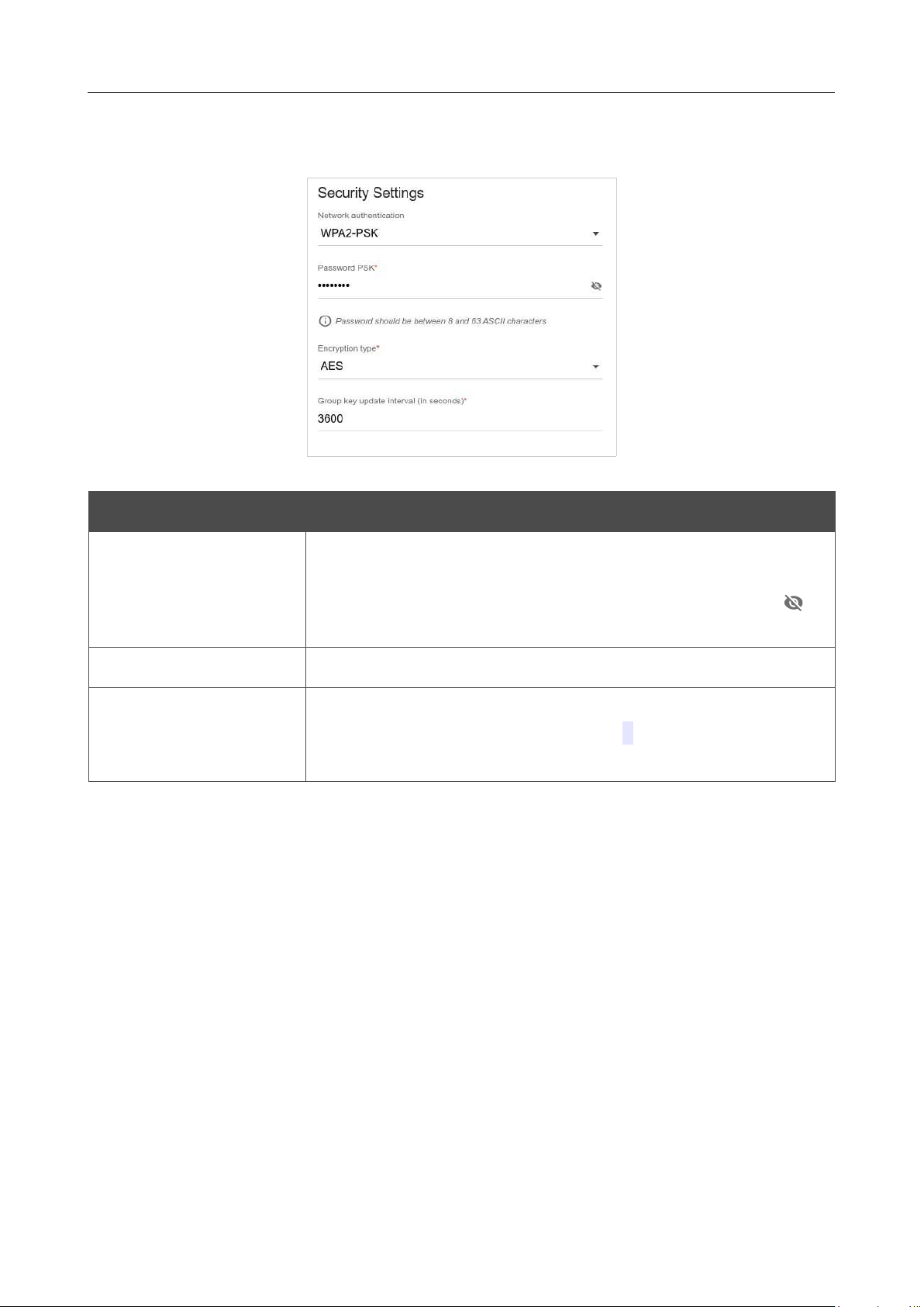
DIR-842V2 AC1200 Wi-Fi Gigabit Router
User Manual
Configuring via Web-based Interface
Page 108 of 200
When the WPA-PSK, WPA2-PSK, WPA-PSK/WPA2-PSK mixed, WPA3-SAE, or WPA2-
PSK/WPA3-SEA mixed value is selected, the following fields are displayed on the page:
Figure 84. The WPA2-PSK value is selected from the Network authentication drop-down list.
Parameter Description
Password PSK
A password for WPA encryption. The password can contain digits,
Latin letters (uppercase and/or lowercase), and other characters
available in the US keyboard layout.4 Click the Show icon ( ) to
display the entered password.
Encryption type An encryption method: TKIP, AES, or TKIP+AES.
Group key update
interval
The time period (in seconds), at the end of which a new key for WPA
encryption is generated. When the value 0 is specified for this field,
the key is not renewed.
4 0-9, A-Z, a-z, space, !"#$%&'()*+,-./:;<=>?@[\]^_`{|}~.
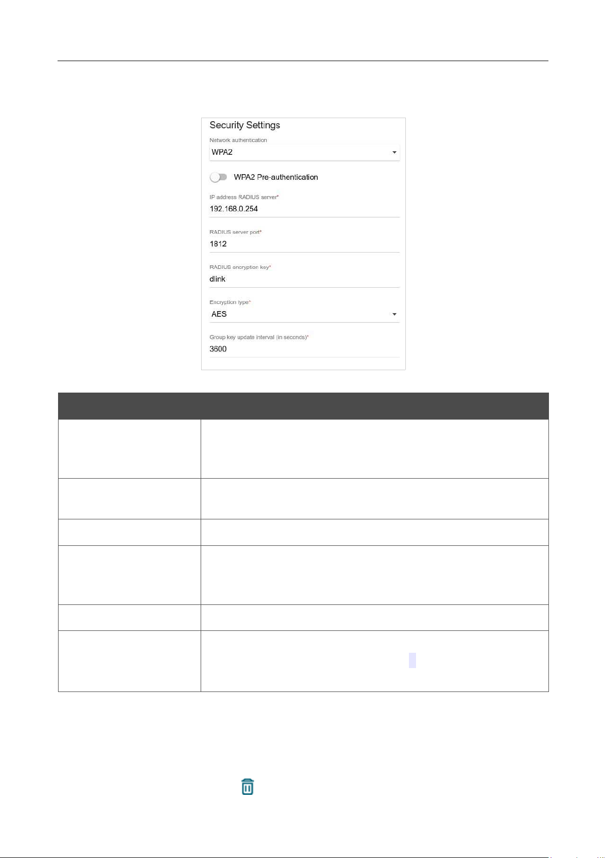
DIR-842V2 AC1200 Wi-Fi Gigabit Router
User Manual
Configuring via Web-based Interface
Page 109 of 200
When the WPA, WPA2, or WPA/WPA2 mixed value is selected, the following settings are
displayed on the page:
Figure 85. The WPA2 value is selected from the Network authentication drop-down list.
Parameter Description
WPA2 Pre-
authentication
Move the switch to the right to activate preliminary authentication
(displayed only for the WPA2 and WPA/WPA2
mixed
authentication types).
IP address RADIUS
server
The IP address of the RADIUS server.
RADIUS server port
A port of the RADIUS server.
RADIUS encryption key
The password which the router uses for communication with the
RADIUS server (the value of this parameter is specified in the
RADIUS server settings).
Encryption type
An encryption method: TKIP, AES, or TKIP+AES.
Group key update
interval
The time period (in seconds), at the end of which a new key for WPA
encryption is generated. When the value 0 is specified for this field,
the key is not renewed.
When you have configured the parameters, click the APPLY button.
To edit the basic or additional wireless network, left-click the relevant line in the table. On the
opened page, change the needed parameters and click the APPLY button.
To remove the additional network, select the checkbox located to the left of the relevant line in the
table and click the DELETE button ( ). Then click the APPLY button.
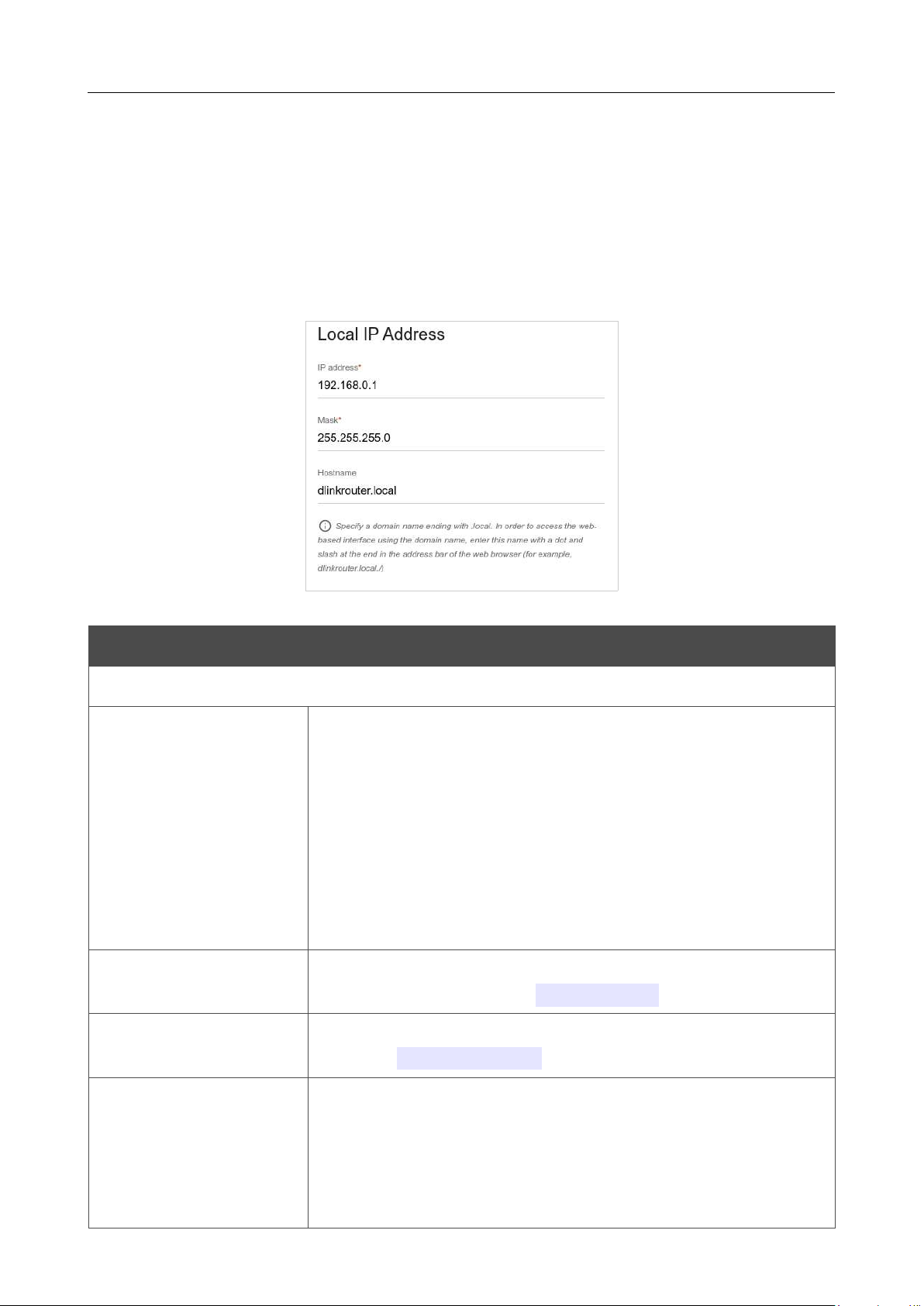
DIR-842V2 AC1200 Wi-Fi Gigabit Router
User Manual
Configuring via Web-based Interface
Page 110 of 200
Settings / Network
To configure the router's local interface, go to the Settings / Network page.
IPv4
Go to the IPv4 tab to change the IPv4 address of the router, configure the built-in DHCP server,
specify MAC address and IPv4 address pairs, or add own DNS records.
Figure 86. Configuring the local interface. The IPv4 tab. The Local IP Address section.
Parameter Description
Local IP Address
Mode of local IP
address assignment
Available if the Access point, Repeater, or Client mode was
selected in the Setup Wizard.
Select the needed value from the drop-down list.
• Static: The IPv4 address, subnet mask, and the gateway IP
address are assigned manually.
• Dynamic: The router automatically obtains these
parameters
from the LAN DHCP server or from the router to which it
connects.
IP address
The IPv4 address of the router in the local subnet. By default, the
following value is specified:
192.168.0.1
.
Mask
The mask of the local subnet. By default, the following value is
specified:
255.255.255.0
.
Gateway IP address
Available if the Access point, Repeater, or Client mode was
selected in the Setup Wizard.
The gateway IPv4 address which is used by the router to connect to
the Internet (e.g., for synchronizing the system time with an NTP
server). Optional.
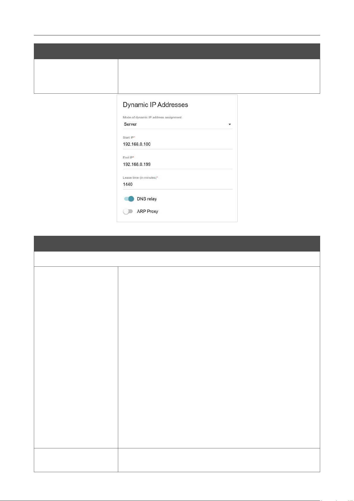
DIR-842V2 AC1200 Wi-Fi Gigabit Router
User Manual
Configuring via Web-based Interface
Page 111 of 200
Parameter Description
Hostname
The name of the device assigned to its IPv4 address in the local
subnet. For Wi-Fi clients, the device is not available by the domain
name, if multicasting is disabled in the additional settings of Wi-Fi.
Figure 87. Configuring the local interface. The IPv4 tab. The Dynamic IP Addresses section.
Parameter Description
Dynamic IP Addresses
Mode of dynamic IP
address assignment
An operating mode of the router's DHCP server.
• Disable: The router's DHCP server is disabled, clients' IP
addresses are assigned manually.
• Server: The router assigns IP addresses to clients
automatically in accordance with the specified parameters.
When this value is selected, the Start IP, End IP, Lease
time fields and the DNS relay switch are displayed on the
tab. Also when this value is selected, the DHCP Options,
Static IP Addresses, and Hosts sections are displayed on
the tab.
• Relay: An external DHCP server is used to assign IP
addresses to clients. When this value is selected, the
External
DHCP server IP, Option 82 Circuit ID,
Option 82
Remote ID, and Option 82 Subscriber ID
fields are
displayed on the tab. Available if the Router or WISP
Repeater mode was selected in the Setup Wizard.
Start IP
The start IP address of the address range used by the DHCP server to
distribute IP addresses to clients.

DIR-842V2 AC1200 Wi-Fi Gigabit Router
User Manual
Configuring via Web-based Interface
Page 112 of 200
Parameter Description
End IP
The end IP address of the address range used by the DHCP server to
distribute IP addresses to clients.
Lease time
The lifetime of IP addresses leased by the DHCP server. At the end
of this period the leased IP address is revoked and can be distributed
to another device, unless the previous device has confirmed the need
to keep the address.
DNS relay
Move the switch to the right so that the devices connected to the router
obtain the address of the router as the DNS server address.
Move the switch to the left so that the devices connected to the
router obtain the address transmitted by the ISP or specified on the
Settings / Internet / DNS page as the DNS server address.
External DHCP server IP
The IP address of the external DHCP server which assigns IP
addresses to the router's clients.
Option 82 Circuit ID
Option 82 Remote ID
Option 82
Subscriber ID
Available if the Router or WISP Repeater mode was selected in
the Setup Wizard.
The value of the relevant field of DHCP option 82. Do not fill in the
fields unless your ISP or the administrator of the external DHCP
server provided these values.
When all needed settings are configured, click the APPLY button.
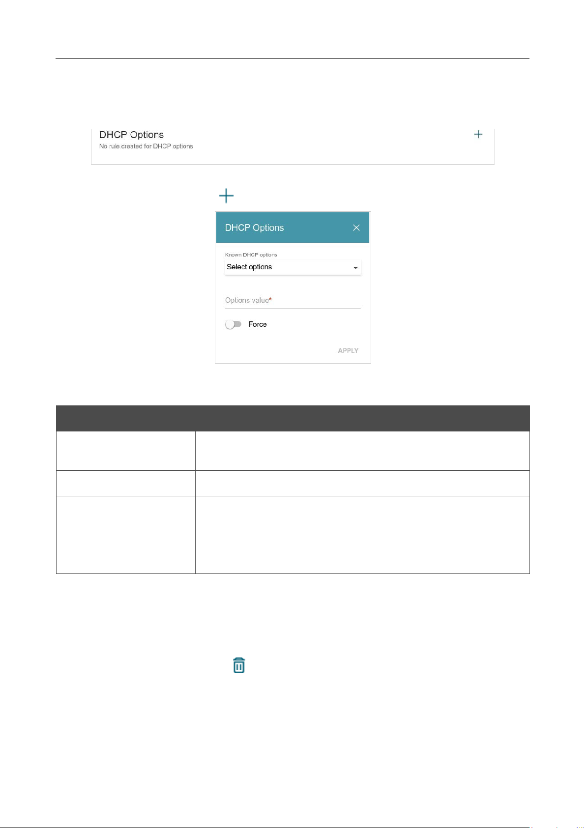
DIR-842V2 AC1200 Wi-Fi Gigabit Router
User Manual
Configuring via Web-based Interface
Page 113 of 200
In the DHCP Options section, you can change default values for some options of DHCP protocol
(IP address, subnet mask, DNS servers) or specify additional parameters which the built-in DHCP
server should send to clients to configure the local network.
Figure 88. Configuring the local interface. The IPv4 tab. The section for configuring DHCP options.
To do this, click the ADD button ( ).
Figure 89. Configuring the local interface. The IPv4 tab. The window for configuring a DHCP option.
In the opened window, you can specify the following parameters:
Parameter Description
Known DHCP options
From the drop-down list, select an option which you want to
configure.
Options value
Specify the value for the selected option.
Force
Move the switch to the right to let the DHCP server send the
selected option regardless of the client's request.
Move the switch to the left to let the DHCP server send the selected
option only when the client requests it.
After specifying the needed parameters, click the APPLY button.
To edit the parameters of an option, left-click the relevant line in the table. In the opened window,
change the needed parameters and click the APPLY button.
To remove the value of an option, select the checkbox located to the left of the relevant line in the
table and click the DELETE button ( ). Then click the APPLY button.

DIR-842V2 AC1200 Wi-Fi Gigabit Router
User Manual
Configuring via Web-based Interface
Page 114 of 200
In the Static IP Addresses section, you can specify MAC address and IPv4 address pairs (set a
fixed IPv4 address in the local area network for a device with a certain MAC address). The router
assigns IPv4 addresses in accordance with the specified pairs only when the DHCP server is enabled
(in the Dynamic IP Addresses section, the Server value is selected from the Mode of dynamic
IP address assignment drop-down list).
Figure 90. Configuring the local interface. The IPv4 tab. The section for creating MAC-IPv4 pairs.
To create a MAC-IPv4 pair, click the ADD button ( ). In the opened window, fill in the MAC
address field. You can choose a device connected to the router's LAN at the moment. To do this,
select the relevant MAC address from the drop-down list (the field will be filled in automatically).
Then in the IP address field, enter an IPv4 address which will be assigned to the device with the
specified MAC address. In the Hostname field, specify a network name of the device for easier
identification (optional). If needed, in the Lease time field, specify a period of time for which the
router's DHCP server provides the IPv4 address to the client. Click the APPLY button.
To create MAC-IPv4 pairs for the devices connected to the router at the moment, click the KNOWN
CLIENTS button. In the opened window, select the needed device and click the OK button. To view
the latest list of the connected devices, click the REFRESH button.
To edit the settings for an existing MAC-IPv4 pair, left-click the relevant line in the table. In the
opened window, change the needed parameters and click the APPLY button.
To remove a MAC-IPv4 pair, select the checkbox located to the left of the relevant line in the table
and click the DELETE button ( ). Then click the APPLY button. Also you can remove a pair in
the editing window.
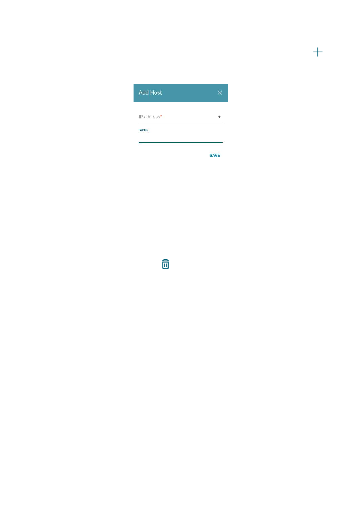
DIR-842V2 AC1200 Wi-Fi Gigabit Router
User Manual
Configuring via Web-based Interface
Page 115 of 200
If needed, you can add your own address resource records. To do this, click the ADD button ( )
in the Hosts section (available if the Router or WISP Repeater mode was selected in the Setup
Wizard).
Figure 91. Configuring the local interface. The IPv4 tab. The window for adding a DNS record.
In the IP address field, specify a host from the internal or external network. You can choose a
device connected to the router's LAN at the moment. To do this, select the relevant IPv4 address from
the drop-down list (the field will be filled in automatically). In the Name field, specify the domain
name to which the specified IPv4 address will correspond. Click the SAVE button.
To edit an existing record, in the Hosts section, select the relevant line in the table. In the opened
window, change the needed parameters and click the SAVE button.
To remove a record, in the Hosts section, select the checkbox located to the left of the relevant line
in the table and click the DELETE button ( ).
After completing the work with records, click the APPLY button.
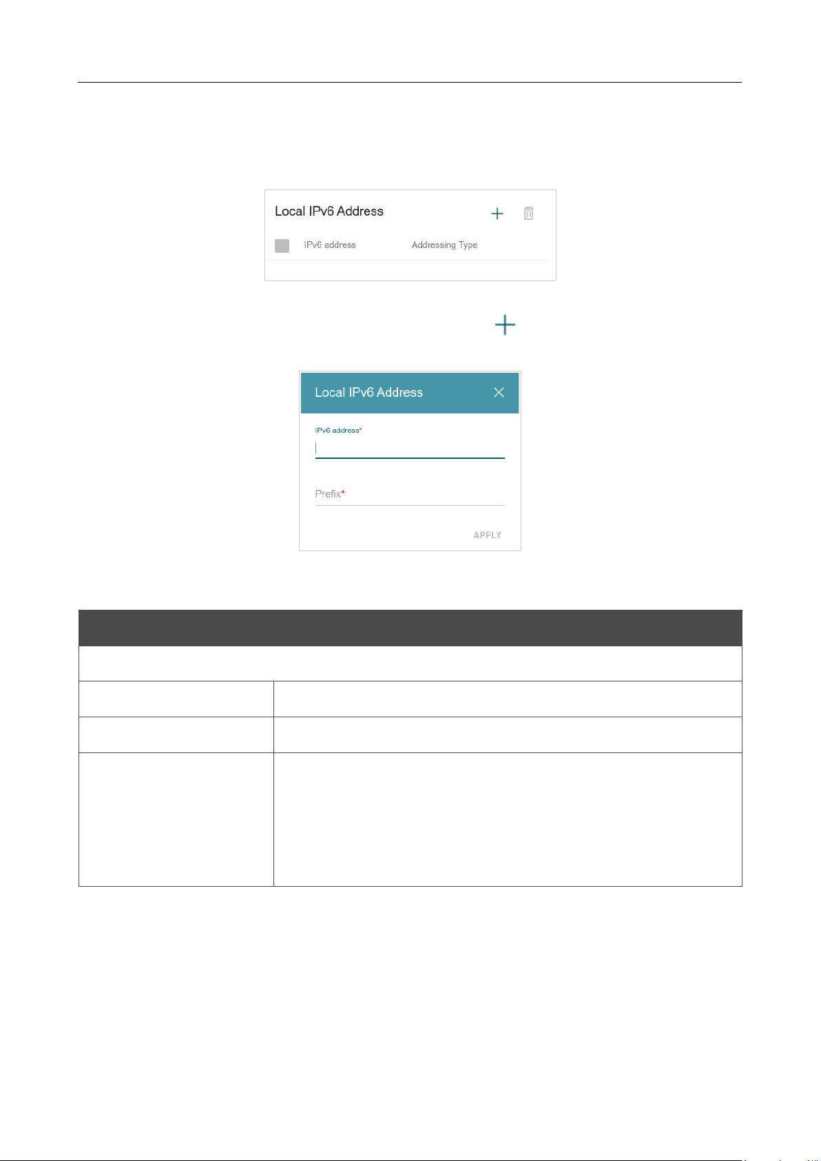
DIR-842V2 AC1200 Wi-Fi Gigabit Router
User Manual
Configuring via Web-based Interface
Page 116 of 200
IPv6
Go to the IPv6 tab to change or add the IPv6 address of the router, configure IPv6 addresses
assignment settings, specify MAC address and IPv6 address pairs, or add own DNS records.
Figure 92. Configuring the local interface. The IPv6 tab. The Local IPv6 Address section.
To add an IPv6 address of the router, click the ADD button ( ). To change the IPv6 address of
the router, select it in the table.
Figure 93. Configuring the local interface. The IPv6 tab. The window for adding an IPv6 address.
In the opened window, you can specify the following parameters:
Parameter Description
Local IPv6 Address
IPv6 address
The IPv6 address of the router in the local subnet.
Prefix
The length of the prefix subnet.
Gateway IPv6 address
Available if the Access point or Repeater mode was selected in
the Setup Wizard.
The gateway IPv6 address which is used by the router to connect to
the Internet (e.g., for synchronizing the system time with an NTP
server). Optional.
Click the APPLY button.
To remove the IPv6 address, select it in the table and click the DELETE button in the opened
window. Then click the APPLY button.
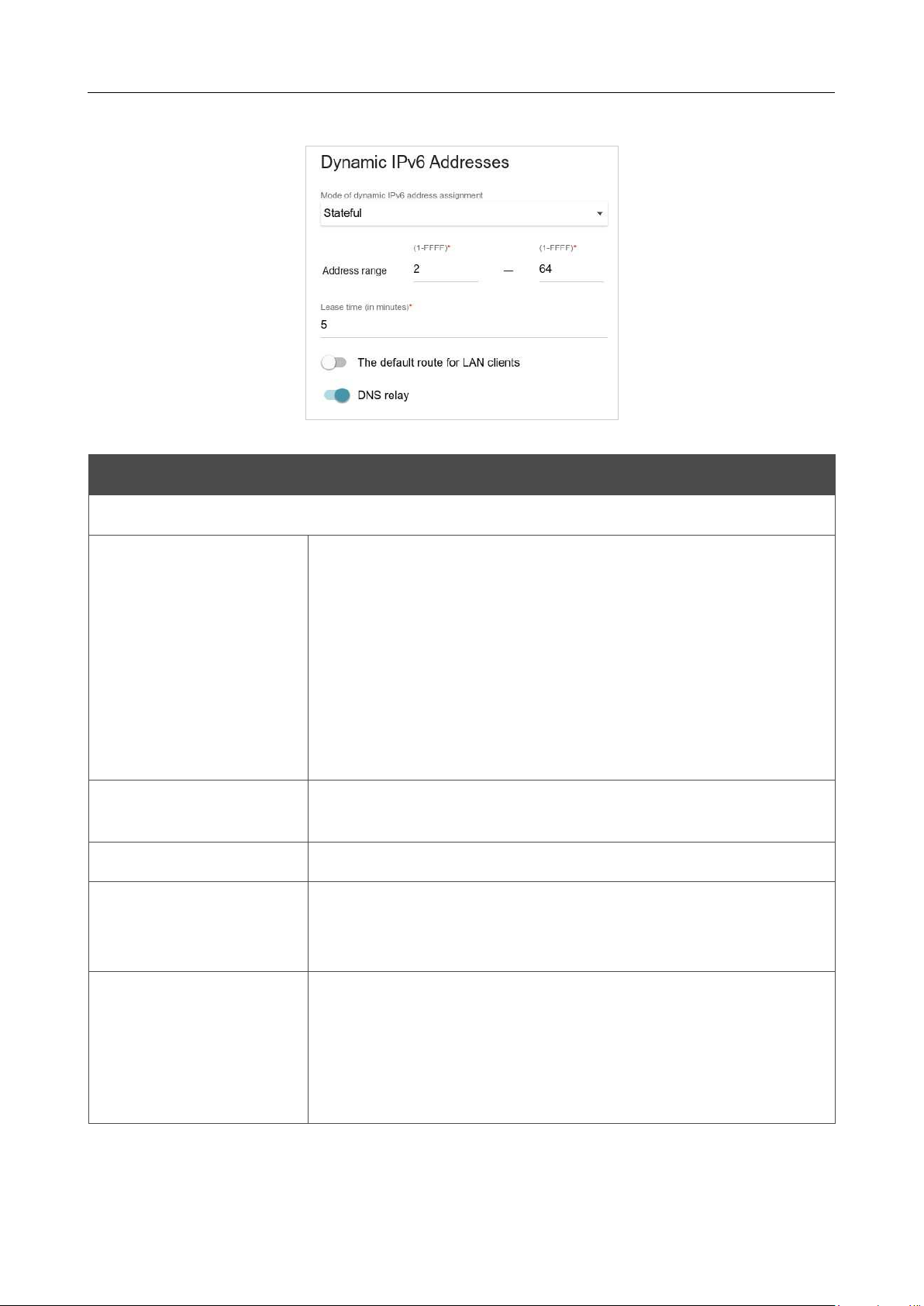
DIR-842V2 AC1200 Wi-Fi Gigabit Router
User Manual
Configuring via Web-based Interface
Page 117 of 200
In the Dynamic IPv6 Addresses section, you can configure IPv6 addresses assignment settings.
Figure 94. Configuring the local interface. The IPv6 tab. The Dynamic IPv6 Addresses section.
Parameter Description
Dynamic IPv6 Addresses
Mode of dynamic IPv6
address assignment
Select the needed value from the drop-down list.
• Disable: Clients' IPv6 addresses are assigned manually.
• Stateful: The built-
in DHCPv6 server of the router allocates
addresses from the range specified in the Address range
fields. Also when this value is selected, the Static IP
Addresses and Hosts sections are displayed on the tab.
• Stateless: Clients themselves configure IPv6 addresses
using the prefix.
Address range
The start and the end values for the latest hextet (16 bit) of the range
of IPv6 addresses which the DHCPv6 server distributes to clients.
Lease time
The lifetime of IPv6 addresses provided to clients.
The default route for
LAN clients
Move the switch to the right to let the clients, that received IPv6
addresses or configured them using the prefix, use the router as the
default IPv6 route.
DNS relay
Move the switch to the right so that the devices connected to the router
obtain the address of the router as the DNS server address.
Move the switch to the left so that the devices connected to the
router obtain the address transmitted by the ISP or specified on the
Settings / Internet / DNS page as the DNS server address.
When all needed settings are configured, click the APPLY button.

DIR-842V2 AC1200 Wi-Fi Gigabit Router
User Manual
Configuring via Web-based Interface
Page 118 of 200
In the Static IP Addresses section, you can specify MAC address and IPv6 address pairs (set a
fixed IPv6 address in the local area network for a device with a certain MAC address). The router
assigns IPv6 addresses in accordance with the specified pairs only when the Stateful value is selected
from the Mode of dynamic IPv6 address assignment drop-down list in the Dynamic IPv6
Addresses section.
Figure 95. Configuring the local interface. The IPv6 tab. The section for creating MAC-IPv6 pairs.
To create a MAC-IPv6 pair, click the ADD button ( ). In the opened window, fill in the MAC
address field. You can choose a device connected to the router's LAN at the moment. To do this,
select the relevant MAC address from the drop-down list (the field will be filled in automatically).
Then in the IP address field, enter an IPv6 address which will be assigned to the device with the
specified MAC address. In the Hostname field, specify a network name of the device for easier
identification (optional). If needed, in the Lease time field, specify a period of time for which the
router's DHCPv6 server provides the IPv6 address to the client. Click the APPLY button.
To create MAC-IPv6 pairs for the devices connected to the router at the moment, click the KNOWN
CLIENTS button. In the opened window, select the needed device and click the OK button. To view
the latest list of the connected devices, click the REFRESH button.
To edit the settings for an existing MAC-IPv6 pair, left-click the relevant line in the table. In the
opened window, change the needed parameters and click the APPLY button.
To remove a MAC-IPv6 pair, select the checkbox located to the left of the relevant line in the table
and click the DELETE button ( ). Then click the APPLY button. Also you can remove a pair in
the editing window.
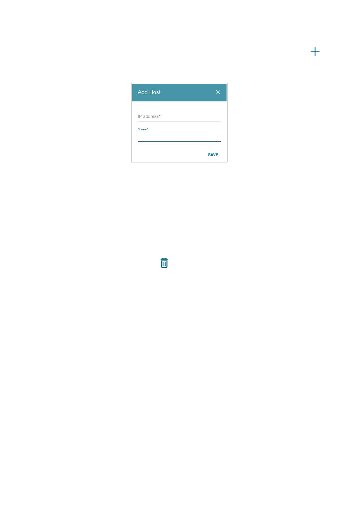
DIR-842V2 AC1200 Wi-Fi Gigabit Router
User Manual
Configuring via Web-based Interface
Page 119 of 200
If needed, you can add your own address resource records. To do this, click the ADD button ( )
in the Hosts section (available if the Router or WISP Repeater mode was selected in the Setup
Wizard).
Figure 96. Configuring the local interface. The IPv6 tab. The window for adding a DNS record.
In the IP address field, specify a host from the internal or external network. You can choose a
device connected to the router's LAN at the moment. To do this, select the relevant IPv6 address from
the drop-down list (the field will be filled in automatically). In the Name field, specify the domain
name to which the specified IPv6 address will correspond. Click the SAVE button.
To edit an existing record, in the Hosts section, select the relevant line in the table. In the opened
window, change the needed parameters and click the SAVE button.
To remove a record, in the Hosts section, select the checkbox located to the left of the relevant line
in the table and click the DELETE button ( ).
After completing the work with records, click the APPLY button.
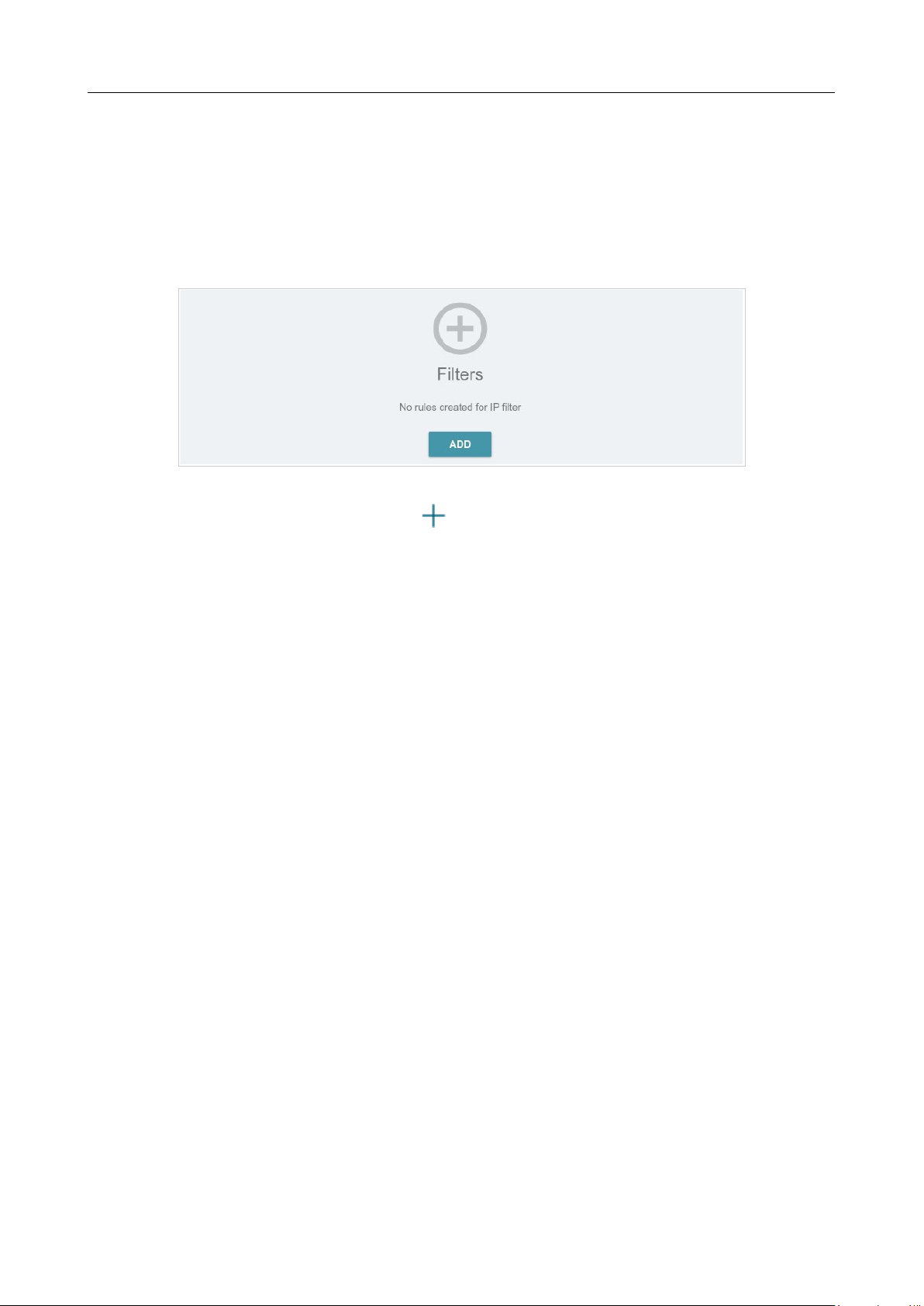
DIR-842V2 AC1200 Wi-Fi Gigabit Router
User Manual
Configuring via Web-based Interface
Page 120 of 200
Functions / Firewall
IP Filter
On the Functions / Firewall / IP filter page, you can create new rules for filtering IP packets and
edit or remove existing rules.
Figure 97. The Functions / Firewall / IP filter page.
To create a new rule, click the ADD button ( ).
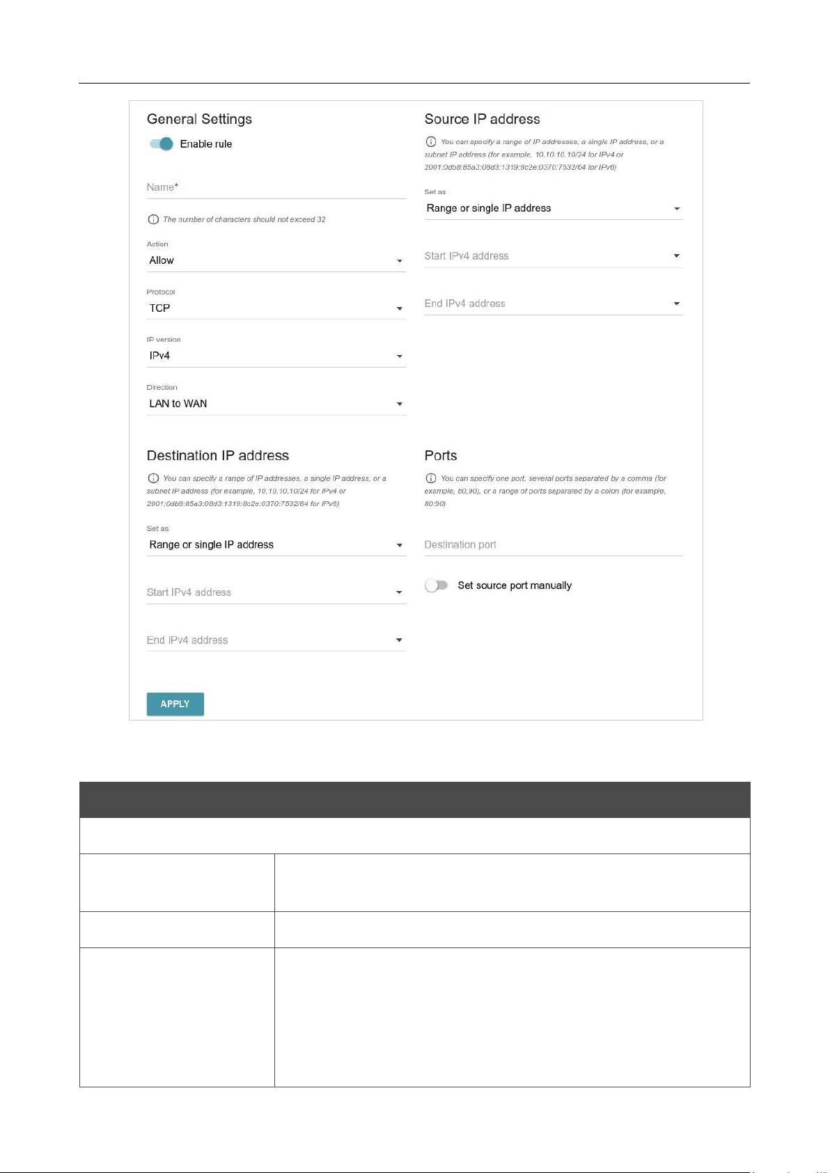
DIR-842V2 AC1200 Wi-Fi Gigabit Router
User Manual
Configuring via Web-based Interface
Page 121 of 200
Figure 98. The page for adding a rule for IP filtering.
You can specify the following parameters:
Parameter Description
General Settings
Enable rule
Move the switch to the right to enable the rule.
Move the switch to the left to disable the rule.
Name
Enter a name for the rule for easier identification.
Action
Select an action for the rule.
• Allow: Allows packet transmission in accordance with the
criteria specified by the rule.
• Deny: Denies packet transmission in accordance with the
criteria specified by the rule.

DIR-842V2 AC1200 Wi-Fi Gigabit Router
User Manual
Configuring via Web-based Interface
Page 122 of 200
Parameter Description
Protocol
A protocol for network packet transmission. Select a value from the
drop-down list.
IP version
An IP version to which the rule will be applied. Select the relevant
value from the drop-down list.
Direction
The direction of network packet transmission to which the rule will
be applied. Select the relevant value from the drop-down list.
• LAN to WAN: The rule will be applied to the packets
transmitted from the local network to the external network.
• WAN to LAN: The rule will be applied to the packets
transmitted from the external network to the local network.
• LAN to Router: The rule will be applied to the packets
transmitted from the local network to DIR-842V2.
• WAN to Router: The rule will be applied to the packets
transmitted from the external network to DIR-842V2.
Source IP Address
Set as
Select the needed value from the drop-down list.
Start IPv4 address /
Start IPv6 address
The source host start IPv4 or IPv6 address.
If it is necessary to specify a single address, leave the End IPv4
address / End IPv6 address field blank.
You can choose a device connected to the router's LAN at the
moment. To do this, select the relevant IPv4 or IPv6 address from the
drop-down list (the field will be filled in automatically).
End IPv4 address /
End IPv6 address
The source host end IPv4 or IPv6 address.
Subnet IPv4 address /
Subnet IPv6 address
The source subnet IPv4 or IPv6 address. The field is displayed when
the Subnet value is selected from the Set as drop-down list.
Destination IP Address
Set as
Select the needed value from the drop-down list.
Start IPv4 address /
Start IPv6 address
The destination host start IPv4 or IPv6 address.
If it is necessary to specify a single address, leave the End IPv4
address / End IPv6 address field blank.
You can choose a device connected to the router's LAN at the
moment. To do this, select the relevant IPv4 or IPv6 address from the
drop-down list (the field will be filled in automatically).

DIR-842V2 AC1200 Wi-Fi Gigabit Router
User Manual
Configuring via Web-based Interface
Page 123 of 200
Parameter Description
End IPv4 address /
End IPv6 address
The destination host end IPv4 or IPv6 address.
Subnet IPv4 address /
Subnet IPv6 address
The destination subnet IPv4 or IPv6 address. The field is displayed
when the Subnet value is selected from the Set as drop-down list.
Ports
Destination port
A port of the destination IP address. You can specify one port,
several
ports separated by a comma, or a range of ports separated by a colon.
Set source port
manually
Move the switch to the right to specify a port of the source IP
address manually. Upon that the Source port field is displayed.
Source port
A port of the source IP address. You can specify one port, several
ports separated by a comma, or a range of ports separated by a colon.
Click the APPLY button.
To set a schedule for the IP filter rule, click the Set Schedule button ( ) in the line
corresponding to this rule. In the opened window, you can create a new schedule (
see the Schedule
section, page 181) or use the existing one. Existing schedules are displayed in the Interval of
execution drop-down list in the simplified mode.
To enable the IP filter rule at the time specified in the schedule and disable it at the other time,
select the Enable rule value from the Action drop-down list and click the SAVE button.
To disable the IP filter rule at the time specified in the schedule and enable it at the other time,
select the Disable rule value from the Action drop-down list and click the SAVE button.
To edit a rule, select the relevant line in the table. In the opened window, change the needed
parameters and click the APPLY button.
To change or delete the schedule for a rule, click the Edit schedule button ( ) in the line
corresponding to this rule. In the opened window, change the parameters and click the SAVE button
or click the DELETE FROM SCHEDULE button.
To remove a rule, select the checkbox located to the left of the relevant line of the table and click
the DELETE button ( ). Also you can remove a rule in the editing window.
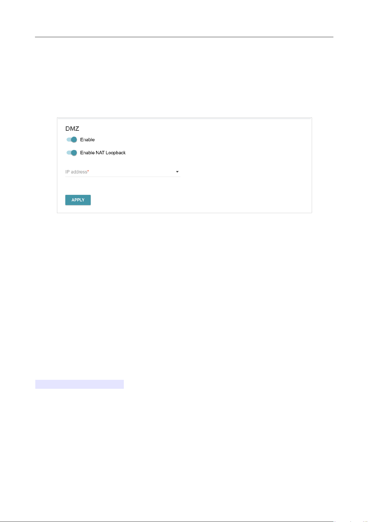
DIR-842V2 AC1200 Wi-Fi Gigabit Router
User Manual
Configuring via Web-based Interface
Page 124 of 200
DMZ
A DMZ is a host or network segment located “between” internal (local) and external (global)
networks. In the router, the DMZ implements the capability to transfer a request coming to a port of
the router from the external network to a specified host of the internal network.
On the Functions / Firewall / DMZ page, you can specify the IP address of the DMZ host.
Figure 99. The Functions / Firewall / DMZ page.
To enable the DMZ, move the Enable switch to the right.
Enter the IP address of a host from your network in the IP address field. To choose a device
connected to the router's LAN at the moment, select the relevant value from the drop-down list (the
field will be filled in automatically).
Move the Enable NAT Loopback switch to the right in order to let the users of the router's LAN
access the DMZ host using the external IP address of the router or its DDNS name (if a DDNS service
is configured). Users from the external network access the router using the same address (or DDNS
name).
Click the APPLY button.
Note that when the DMZ is enabled, all traffic coming to a port of the WAN interface of the router is
directed to the same port of the specified IP address. Also note that virtual servers have higher priority
than the DMZ host. In other words, if there has been created a virtual server that directs traffic from
external port 80 to a port of the device from the router's local network, then entering
http://router_WAN_IP in the address bar, users of the external network are directed to the
specified port and IP address configured for the virtual server, but not to port 80 of the device with
the IP address specified on the Functions / Firewall / DMZ page.
To disable the DMZ, move the Enable switch to the left and click the APPLY button.
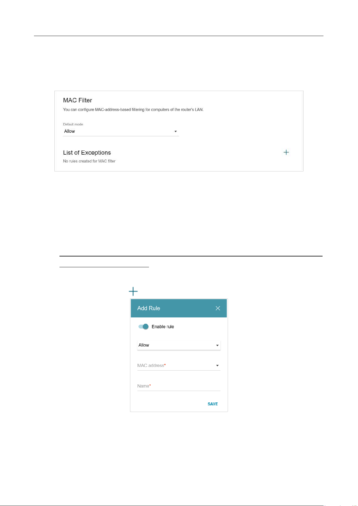
DIR-842V2 AC1200 Wi-Fi Gigabit Router
User Manual
Configuring via Web-based Interface
Page 125 of 200
MAC Filter
On the Functions / Firewall / MAC Filter page, you can configure MAC-address-based filtering
for computers of the router's LAN.
Figure 100. The Functions / Firewall / MAC Filter page.
Select the needed action from the drop-down list in the Default mode section to configure
filtering for all devices of the router's network:
• Allow: Allows access to the router's network and to the Internet for devices (the value is
specified by default);
• Deny: Blocks access to the router's network for devices.
!
You can use the Deny mode only if an active rule which allows access to the device's
network is created on the page.
To create a rule (specify a MAC address of a device for which the specified filtering mode will be
applied), click the ADD button ( ).
Figure 101. The window for adding a rule for the MAC filter.

DIR-842V2 AC1200 Wi-Fi Gigabit Router
User Manual
Configuring via Web-based Interface
Page 126 of 200
In the opened window, you can specify the following parameters:
Parameter Description
Enable rule
Move the switch to the right to enable the rule.
Move the switch to the left to disable the rule.
Action
Select an action for the rule.
• Deny: Blocks access to the Internet for the device with the
specified MAC address even if the default mode allows access
for all devices.
• Allow: Allows access to the router's network and to the
Internet for the device with the specified MAC address even
if the default mode denies access for all devices.
MAC address
The MAC address of a device from the router's LAN. You can enter
the MAC address of a device connected to the router's LAN at the
moment. To do this, select the relevant device from the drop-down
list (the field will be filled in automatically).
Name
The name of the device for easier identification. You can specify
any name.
After specifying the needed parameters, click the SAVE button.
To set a schedule for the MAC filter rule, click the Set Schedule button ( ) in the line
corresponding to this rule. In the opened window, you can create a new schedule (
see the Schedule
section, page 181) or use the existing one. Existing schedules are displayed in the Interval of
execution drop-down list in the simplified mode.
To enable the MAC filter rule at the time specified in the schedule and disable it at the other time,
select the Enable rule value from the Action drop-down list and click the SAVE button.
To disable the MAC filter rule at the time specified in the schedule and enable it at the other time,
select the Disable rule value from the Action drop-down list and click the SAVE button.
To edit a rule, select the relevant line in the table. In the opened window, change the needed
parameters and click the SAVE button.
To change or delete the schedule for a rule, click the Edit schedule button ( ) in the line
corresponding to this rule. In the opened window, change the parameters and click the SAVE button
or click the DELETE FROM SCHEDULE button.
To remove a rule, select the checkbox located to the left of the relevant line of the table and click
the DELETE button ( ). Also you can remove a rule in the editing window.
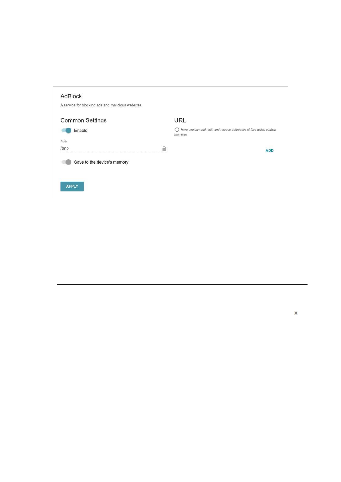
DIR-842V2 AC1200 Wi-Fi Gigabit Router
User Manual
Configuring via Web-based Interface
Page 127 of 200
AdBlock
On the Functions / Firewall / AdBlock page, you can enable the function of blocking
advertisements which appear during web surfing5.
Figure 102. The Functions / Firewall / AdBlock page.
To enable the advertisements blocking function, in the Common Settings section, move the
Enable switch to the right. Then in the URL section, click the ADD button and in the line displayed,
enter a URL address of a file containing the list of advertising web sites which should be blocked.
The file with the list of advertising web sites is stored in the device’s memory. Upon that the Path
field is unavailable for editing and the Save to the device’s memory switch is moved to the right..
Click the APPLY button.
!
Files saved to the device’s memory are updated upon every reboot of the router or its or
firmware update. In case the file is not available at that moment, the list of web sites to be
blocked will not be received.
If you don't want to use a file for blocking advertisements any longer, click the Delete icon ( ) in the
line of the URL address of the relevant file. Then click the APPLY button.
To disable the advertisements blocking function, move the Enable switch to the left and click the
APPLY button.

DIR-842V2 AC1200 Wi-Fi Gigabit Router
User Manual
Configuring via Web-based Interface
Page 128 of 200
5 Will be available in future software versions.
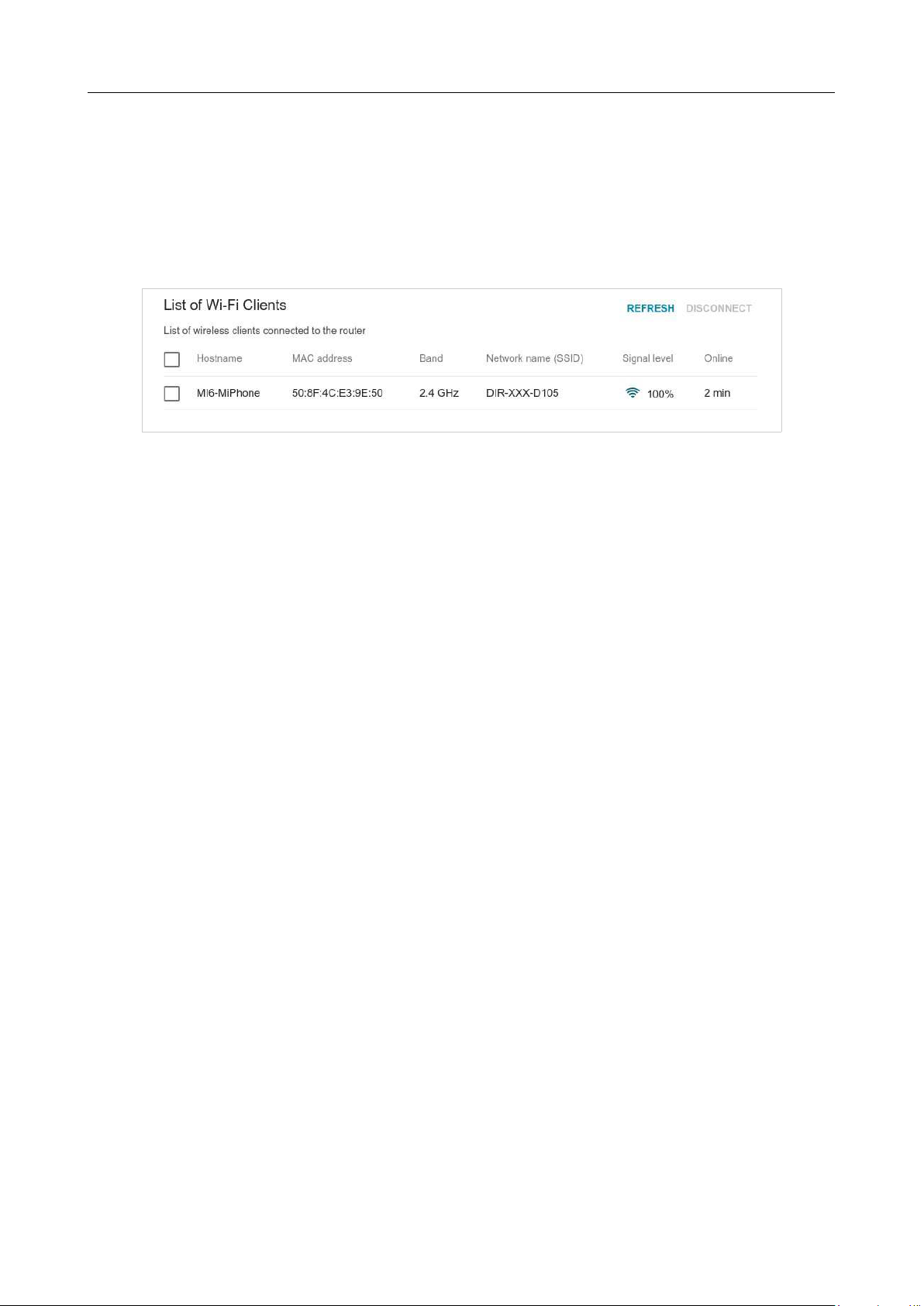
DIR-842V2 AC1200 Wi-Fi Gigabit Router
User Manual
Configuring via Web-based Interface
Page 129 of 200
Functions / Wi-Fi
Client Management
On the Functions / Wi-Fi / Client Management page, you can view the list of wireless clients
connected to the router.
Figure 103. The page for managing the wireless clients.
If you want to disconnect a wireless device from your WLAN, select the checkbox in the line
containing the MAC address of this device and click the DISCONNECT button.
To view the latest data on the devices connected to the WLAN, click the REFRESH button.
To view data on a connected device, left-click the line containing the MAC address of this device.
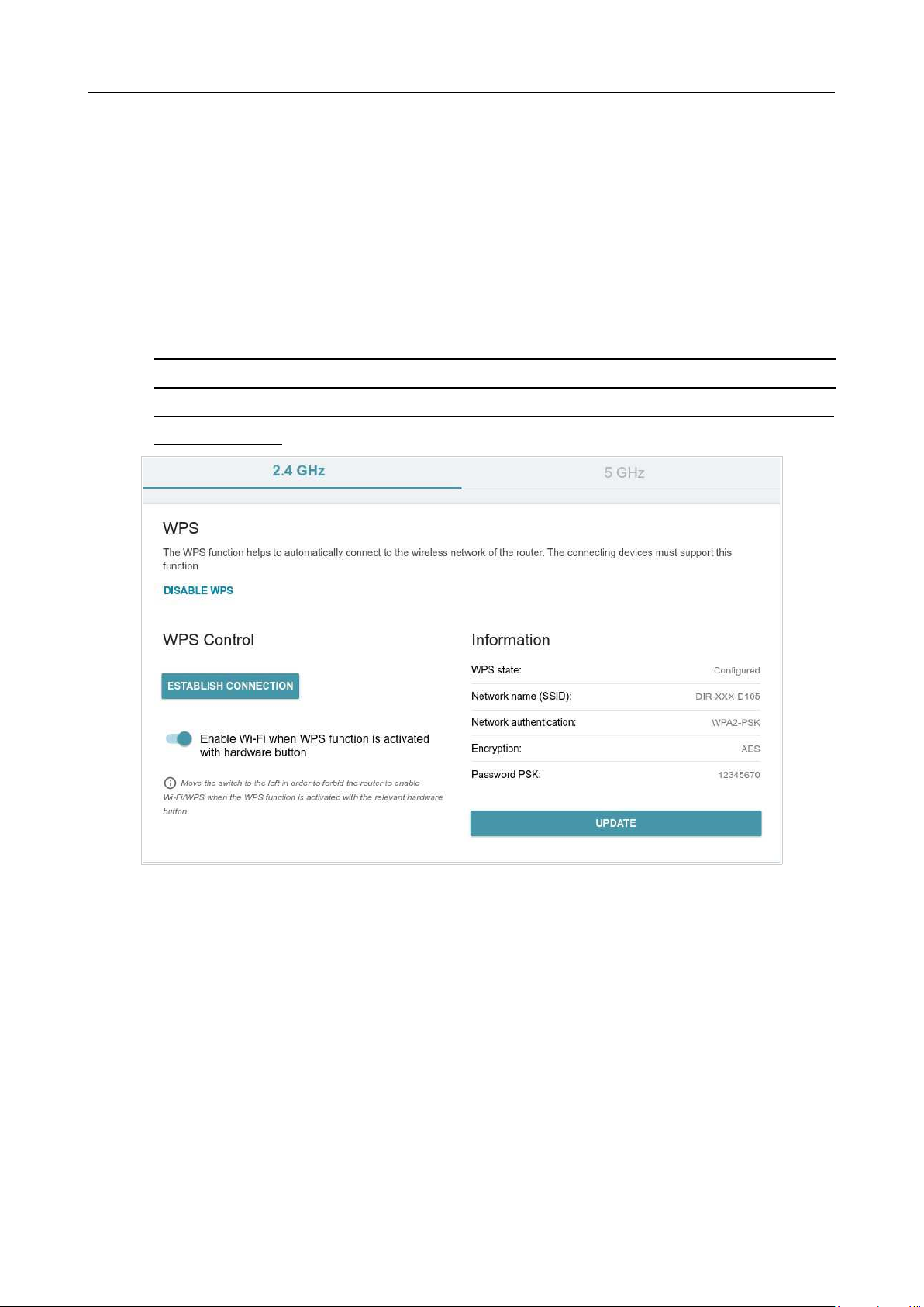
DIR-842V2 AC1200 Wi-Fi Gigabit Router
User Manual
Configuring via Web-based Interface
Page 130 of 200
WPS
On the Functions / Wi-Fi / WPS page, you can enable the function for configuration of the WLAN.
The WPS function helps to configure the wireless network automatically. Devices connecting to the
wireless network via the WPS function must support the WPS function.
!
The WPS function allows adding devices only to the basic wireless network of the router.
!
Before using the function you need to configure one of the following authentication types:
Open with no encryption, WPA2-PSK or WPA-PSK/WPA2-PSK mixed with the AES
encryption method. When other security settings are specified, controls of the WPS page
are not available.
Figure 104. The page for configuring the WPS function.
You can activate the WPS function via the web-based interface or the hardware WPS button on the
cover of the device.
To activate the WPS function via the hardware button, move the Enable Wi-Fi when WPS
function is activated with hardware button switch to the right on the tabs of both bands. Then,
with the device turned on, push the button, hold it for 2 seconds, and release. Upon pressing the button,
the wireless interfaces of the device are enabled if they were disabled before.
If you want to disable activating the WPS function via the hardware button, move the Enable Wi-
Fi when WPS function is activated with hardware button switch to the left on the tabs of
both bands and make sure that the WPS function is not activated via the web-based interface.
To activate the WPS function via the web-based interface, click the ENABLE WPS button.

DIR-842V2 AC1200 Wi-Fi Gigabit Router
User Manual
Configuring via Web-based Interface
Page 131 of 200
When the WPS function is enabled, the Information section is available on the page.
Parameter Description
WPS state
The state of the WPS function:
• Configured (all needed settings are specified; these settings
will be used upon establishing the wireless connection)
• Unconfigured (after activating the WPS function, the SSID
and the encryption key will be configured automatically, the
network authentication type will be changed to WPA2-PSK).
Network name (SSID)
The name of the router's wireless network.
Network authentication
The network authentication type specified for the wireless network.
Encryption
The encryption type specified for the wireless network.
Password PSK
The encryption password specified for the wireless network.
UPDATE
Click the button to update the data on the page.

DIR-842V2 AC1200 Wi-Fi Gigabit Router
User Manual
Configuring via Web-based Interface
Page 132 of 200
Using WPS Function via Web-based Interface
To connect to the basic wireless network via the WPS function, follow the next steps:
1. Click the ENABLE WPS button.
2. In the WPS Control section, click the ESTABLISH CONNECTION button.
3. Select the PBC method in the software of the wireless device that you want to connect to the
router's WLAN.
4. Click the relevant button in the software or press the WPS button on the cover of the
wireless device that you want to connect to the WLAN.
5. Right after that, click the CONNECT button in the web-based interface of the router.
Using WPS Function without Web-based Interface
You can use the WPS function without accessing the web-based interface of the router. To do this,
you need to configure the following router's settings:
1. Specify relevant security settings for the wireless network of the router.
2. Make sure that the Enable Wi-Fi when WPS function is activated with hardware
button switch is moved to the right on the tabs of both bands.
3. Click the ENABLE WPS button.
4. Close the web-based interface (click the Logout line of the menu).
Later you will be able to add wireless devices to the WLAN by pressing the WPS button of the
router.
1. Select the PBC method in the software of the wireless device that you want to connect to the
router's WLAN.
2. Click the relevant button in the software or press the WPS button on the cover of the
wireless device that you want to connect to the WLAN.
3. Press the WPS button of the router and release.
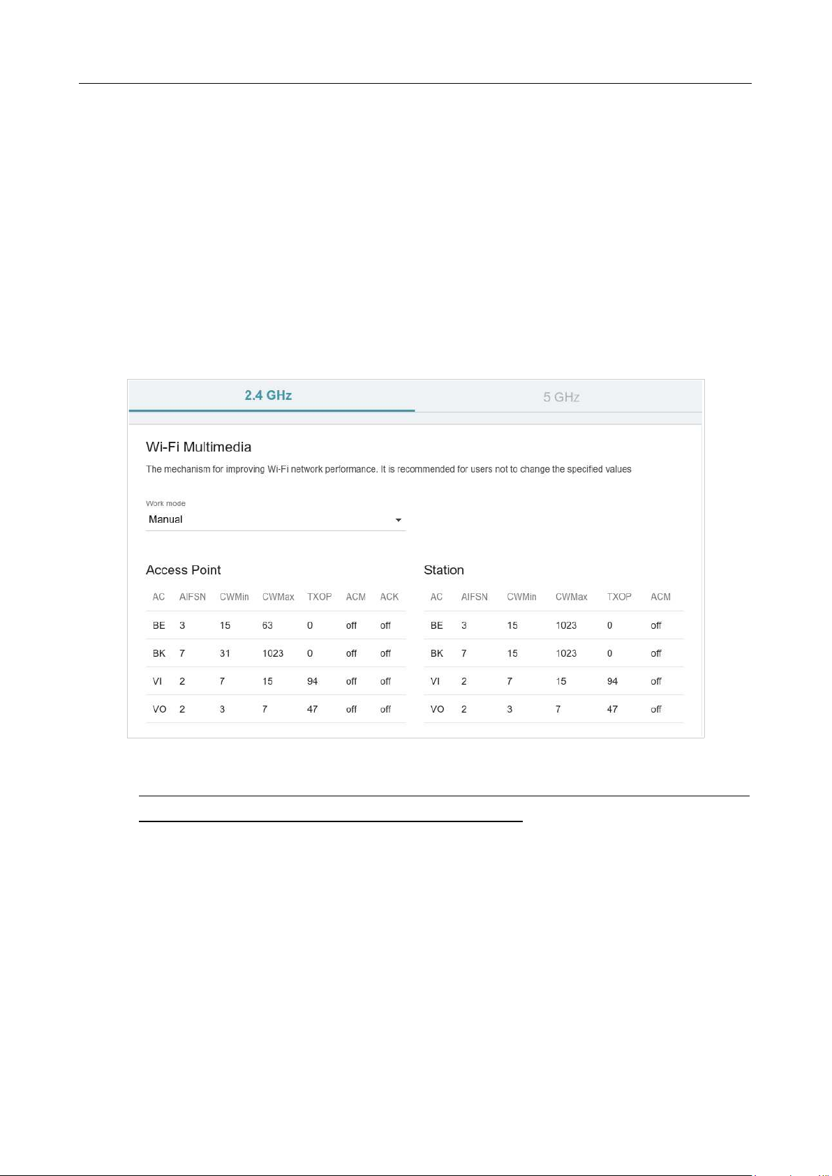
DIR-842V2 AC1200 Wi-Fi Gigabit Router
User Manual
Configuring via Web-based Interface
Page 133 of 200
WMM
On the Functions / Wi-Fi / WMM page, you can enable the Wi-Fi Multimedia function.
The WMM function implements the QoS features for Wi-Fi networks. It helps to improve the
quality of data transfer over Wi-Fi networks by prioritizing different types of traffic.
Select the needed action from the Work mode drop-down list to configure the WMM function:
• Auto: the settings of the WMM function are configured automatically (the value is
specified by default).
• Manual: the settings of the WMM function are configured manually. When this value is
selected, the Access Point and Station sections are displayed on the page.
Figure 105. The page for configuring the WMM function.
!
All needed settings for the WMM function are specified in the device's system. Changing
parameters manually may negatively affect your WLAN!
The WMM function allows assigning priorities for four Access Categories (AC):
• BK (Background), low priority traffic (print jobs, file downloads, etc.).
• BE (Best Effort), traffic from legacy devices or devices/applications that do not support
QoS.
• VI (Video).
• VO (Voice).
Parameters of the Access Categories are defined for both the router itself (in the Access Point
section) and wireless devices connected to it (in the Station section).
To edit the parameters of an Access Category, left-click the relevant line. In the opened window,
change the needed parameters.
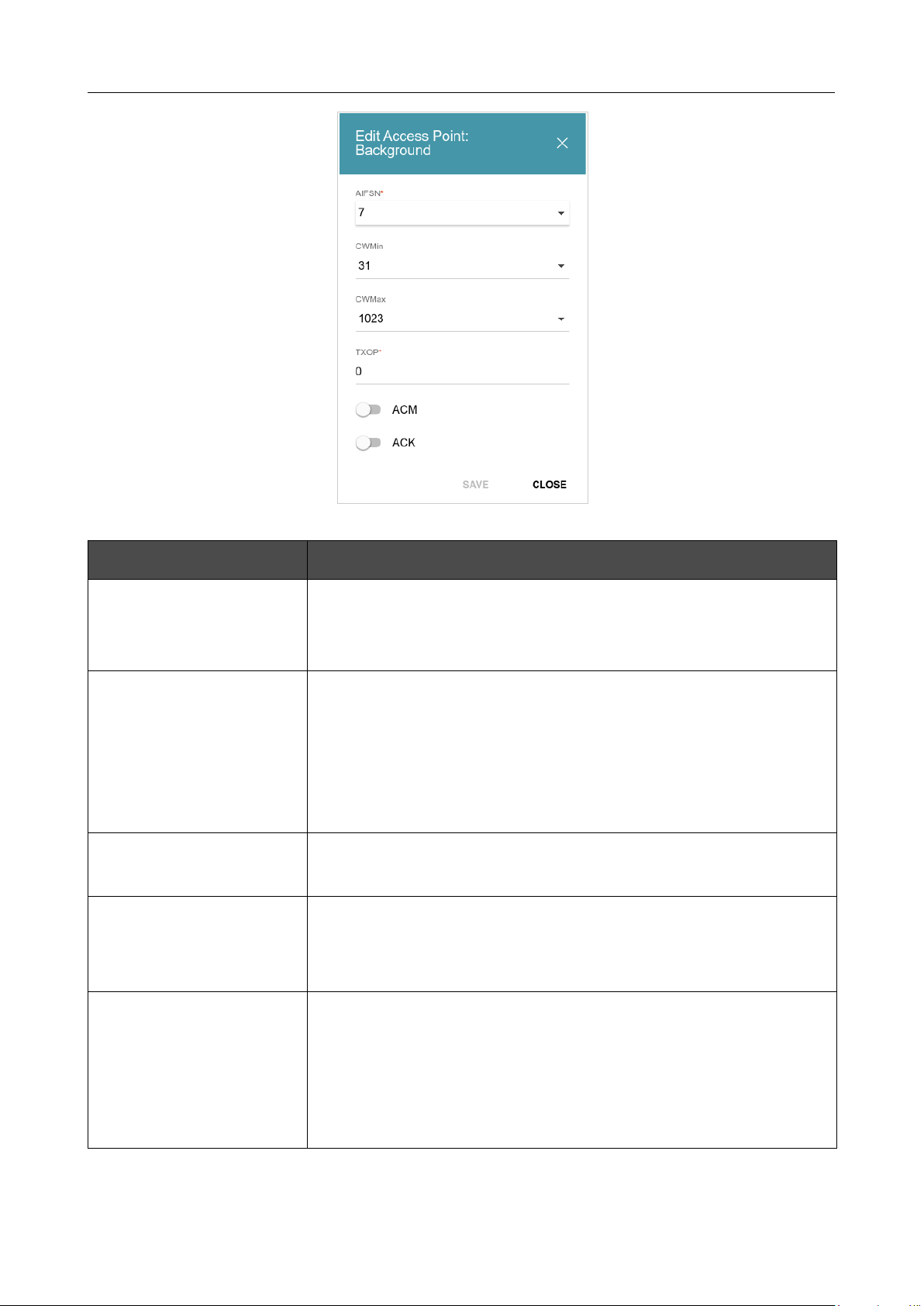
DIR-842V2 AC1200 Wi-Fi Gigabit Router
User Manual
Configuring via Web-based Interface
Page 134 of 200
Figure 106. The window for changing parameters of the WMM function.
Parameter Description
AIFSN
Arbitrary Inter-Frame Space Number. This parameter influences
time delays for the relevant Access Category. The lower the value,
the higher is the Access Category priority.
CWMin/CWMax
Contention Window Minimum/Contention Window Maximum. Both
fields influence time delays for the relevant Access Category. The
CWMax field value should not be lower, than the CWMin field
value. The lower the difference between the CWMax field value and
the CWMin field value, the higher is the Access Category priority.
TXOP
Transmission Opportunity. The higher the value, the higher is the
Access Category priority.
ACM
Admission Control Mandatory.
If the switch is moved to the right, the device cannot use the
relevant Access Category.
ACK
Acknowledgment. Answering response requests while transmitting.
Displayed only in the Access Point section.
If the switch is moved to the left, the router answers requests.
If the switch is moved to the right, the router does not answer
requests.
Click the SAVE button.
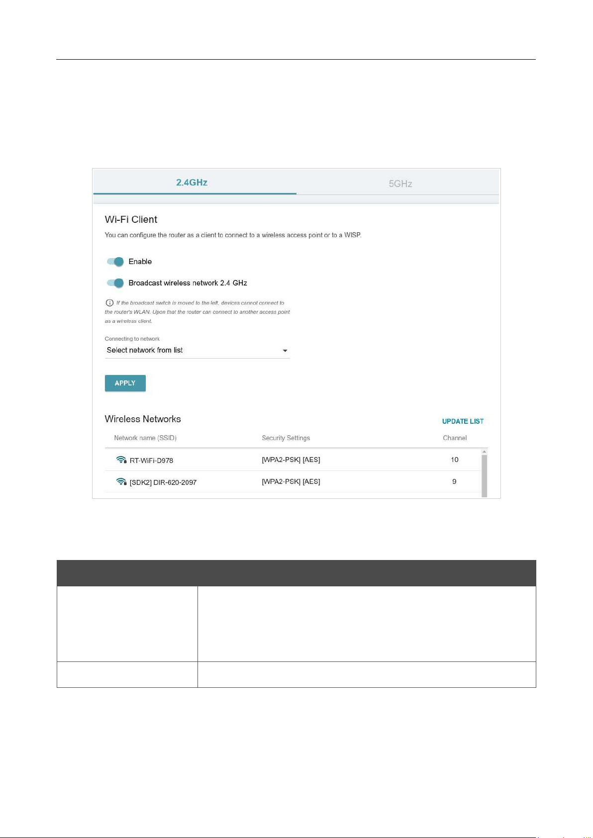
DIR-842V2 AC1200 Wi-Fi Gigabit Router
User Manual
Configuring via Web-based Interface
Page 135 of 200
Client
On the Functions / Wi-Fi / Client page, you can configure the router as a client to connect to a
wireless access point or to a WISP. To configure the 2.4GHz band or 5GHz band, go to the relevant
tab.
Figure 107. The page for configuring the client mode.
To configure the router as a client, move the Enable switch to the right. Upon that the following
fields are displayed on the page:
Parameter Description
Broadcast wireless
network 2.4 GHz /
Broadcast wireless
network 5 GHz
If the switch is moved to the left, devices cannot connect to the
router's WLAN. Upon that the router can connect to another access
point as a wireless client.
Connecting to network
A method for connecting to another access point.
In the Wireless Networks section, the list of available wireless networks is displayed. To view
the latest data on available wireless networks, click the UPDATE LIST button.
To connect to a wireless network from the list, select the needed network. Move the Network
options switch to the right to view more detailed information on the network to which the router
connects. If a password is required, enter it in the relevant field. Click the CONNECT button.

DIR-842V2 AC1200 Wi-Fi Gigabit Router
User Manual
Configuring via Web-based Interface
Page 136 of 200
To connect to a hidden network, select the Connect to hidden network value from the
Connecting to network drop-down list. Then enter the network name in the Network name
(SSID) field. If needed, fill in the BSSID field. Then select the needed type of authentication from
the Network authentication drop-down list.
When the Open or WEP authentication type is selected, the following settings are displayed on the
page:
Parameter Description
Enable encryption WEP
For Open authentication type only.
To activate WEP encryption, move the switch to the right. Upon that
the Default key ID drop-down list, the Encryption key WEP as
HEX switch, and four Encryption key
fields are displayed on the
page.
Default key ID
The number of the key (from first to fourth) which will be used for
WEP encryption.
Encryption key WEP as
HEX
Move the switch to the right to set a hexadecimal number as a key
for encryption.
Encryption key
(1-4)
Keys for WEP encryption. The router uses the key selected from the
Default key ID drop-down list. It is required to specify all the fields.
Click the Show icon ( ) to display the entered key.
When the W WPA-PSK, WPA2-PSK, WPA-PSK/WPA2-PSK mixed, WPA3-SAE, or WPA2-
PSK/WPA3-SAE mixed authentication type is selected, the following field is displayed:
Parameter Description
Password PSK
A password for WPA encryption. Click the Show icon ( ) to
display the entered password.
When you have configured the parameters, click the APPLY button.
When connecting to a wireless access point, the wireless channel of DIR-842V2 will switch to the
channel of the access point to which you have connected.
In addition, the Connection Information section in which you can view the connection status and
the network basic parameters is displayed.
If you want to connect to the WISP network, after configuring the device as a client, you need to
create a WAN connection with relevant parameters for the WiFiClient_2GHz_1 interface in the
2.4GHz band or for the WiFiClient_5GHz_1 interface in the 5GHz band.
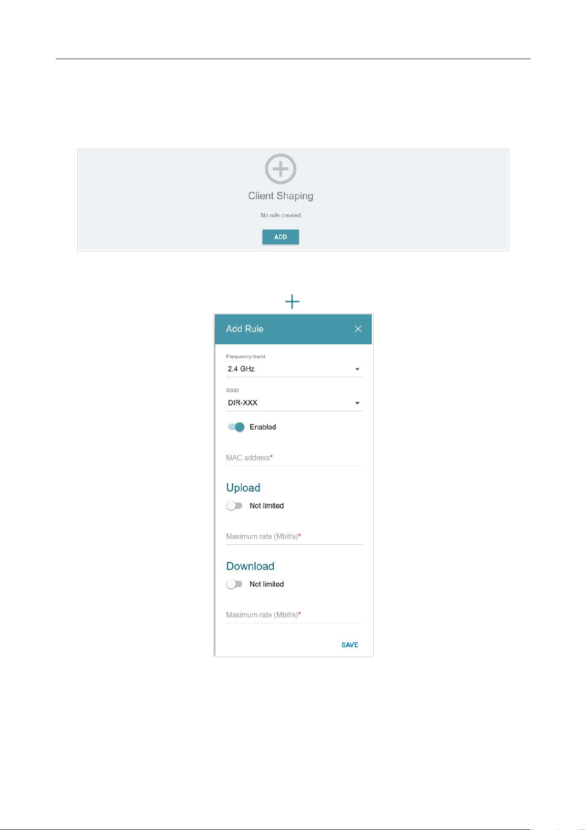
DIR-842V2 AC1200 Wi-Fi Gigabit Router
User Manual
Configuring via Web-based Interface
Page 137 of 200
Client Shaping
On the Functions / Wi-Fi / Client Shaping page, you can limit the maximum bandwidth of
upstream and downstream traffic for each wireless client of the router by its MAC address.
Figure 108. The Functions / Wi-Fi / Client Shaping page.
If you want to limit the maximum bandwidth of traffic for the router’s wireless client, create a
relevant rule. To do this, click the ADD button ( ).
Figure 109. The window for setting up rate limit.

DIR-842V2 AC1200 Wi-Fi Gigabit Router
User Manual
Configuring via Web-based Interface
Page 138 of 200
In the opened window, you can specify the following parameters:
Parameter Description
Frequency band
From the drop-down list, select a band of the wireless network.
SSID
A wireless network to which the rule will be applied. Select the
needed value from the drop-down list.
Enabled
If the switch is moved to the right, the rule is active.
Move the switch to the left to disable the rule.
MAC address
In the field, enter the MAC address to which the rule will be
applied.
Upload
Maximum rate
Specify the maximum value of the upstream traffic rate (Mbit/s) or
move the Not limited switch to the right not to limit the maximum
bandwidth of upstream traffic.
Download
Maximum rate
Specify the maximum value of the downstream traffic rate (Mbit/s)
or move the Not limited switch to the right not to limit the maximum
bandwidth of downstream traffic.
After specifying the needed parameters, click the SAVE button.
To edit a rule, left-click the relevant rule. In the opened window, change the needed parameters and
click the SAVE button.
To remove a rule, select the checkbox located to the left of the relevant line in the table and click
the DELETE button ( ).
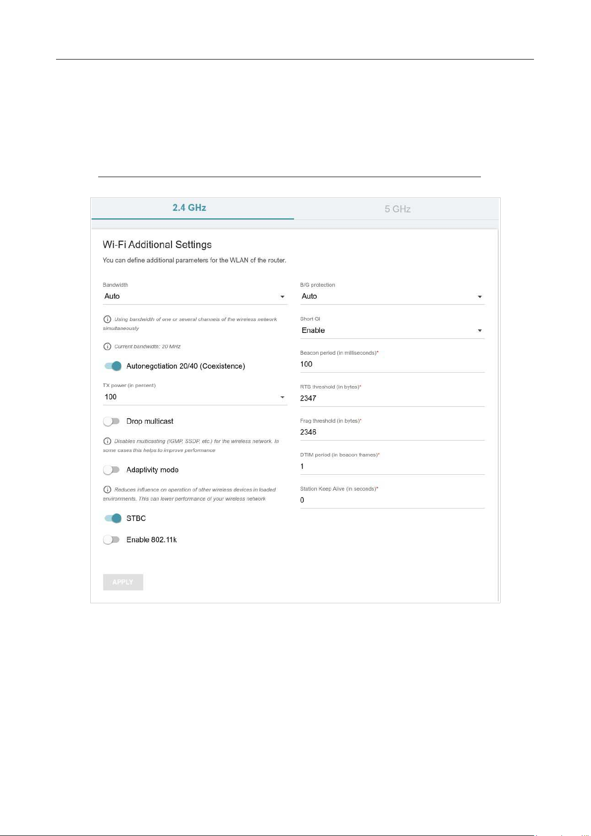
DIR-842V2 AC1200 Wi-Fi Gigabit Router
User Manual
Configuring via Web-based Interface
Page 139 of 200
Additional
On page of the Functions / Wi-Fi / Additional section, you can define additional parameters for
the WLAN of the router. To configure the 2.4GHz band or 5GHz band, go to the relevant tab.
!
Changing parameters presented on this page may negatively affect your WLAN!
Figure 110. Additional settings of the WLAN.

DIR-842V2 AC1200 Wi-Fi Gigabit Router
User Manual
Configuring via Web-based Interface
Page 140 of 200
The following fields are available on the page:
Parameter Description
Bandwidth
The channel bandwidth for 802.11n standard in the 2.4GHz band
(the 2.4 GHz tab).
• 20 MHz: 802.11n clients operate at 20MHz channels.
• 20/40 MHz: 802.11n clients operate at 20MHz or 40MHz
channels.
• Auto: the router automatically chooses the most suitable
channel bandwidth for 802.11n clients.
The channel bandwidth for 802.11n and 802.11ac standards in 5GHz
band (the 5 GHz tab).
• 20 MHz: 802.11n and 802.11ac clients operate at 20MHz
channels.
• 20/40 MHz: 802.11n and 802.11ac clients operate at 20MHz
or 40MHz channels.
• 20/40/80 MHz: 802.11ac clients operate at 20MHz, 40MHz,
or 80MHz channels.
• Auto: the router automatically chooses the most suitable
channel bandwidth for 802.11n and 802.11ac clients.
Autonegotiation
20/40 (Coexistence)
Available on the 2.4 GHz tab.
Move the switch to the right to let the router automatically choose the
channel bandwidth (20MHz or 40MHz) depending on
availability of
other APs within its operational range (this setting can
substantially
lower the data transfer rate of your wireless network).
The switch is
displayed when the 20/40 MHz value is selected from
the
Bandwidth drop-down list.
TX Power
The transmit power (in percentage terms) of the router.
Drop multicast
Move the switch to the right to disable multicasting for the router's
WLAN. Move the switch to the left to enable multicasting from the
WAN connection selected on the Functions / Advanced /
IGMP/MLD page.
Adaptivity mode
Move the switch to the right to prevent your wireless network from
interfering with radars and other mobile or stationary radio systems.
Such a setting can slow down the router's WLAN.

DIR-842V2 AC1200 Wi-Fi Gigabit Router
User Manual
Configuring via Web-based Interface
Page 141 of 200
STBC
The STBC (Space-time block coding) technique allows increasing
data transfer reliability even for portable devices equipped with poor
antennas (smartphones, pads, etc.) due to using several data streams
and processing several versions or received data.
Move the switch to the right if you need to use the STBC technique.

DIR-842V2 AC1200 Wi-Fi Gigabit Router
User Manual
Configuring via Web-based Interface
Page 142 of 200
Parameter Description
Enable 802.11k
802.11k standard allows faster roaming of clients between access
points within the same network. Clients supporting 802.11k standard
can request a list of neighbor access points with their signal levels and
Wi-Fi channel numbers. The device does not need to probe all of
the
available channels, but selects an access point to roam to from the
list.
Move the switch to the right if you need to use 802.11k standard.
B/G protection
Available on the 2.4 GHz tab.
The 802.11b and 802.11g protection function is used to minimize
collisions between devices of your wireless network.
Select a value from the drop-down list.
• Auto: The protection function is enabled and disabled
automatically depending on the state of the network (this
value
is recommended if your wireless local area network consists
of both 802.11b and 802.11g devices).
• Always On: The protection function is always enabled (this
setting can substantially lower the efficiency of your wireless
network).
• Always Off: The protection function is always disabled.
Short GI
Guard interval (in nanoseconds). This parameter defines the interval
between symbols transmitted when the router is communicating to
wireless devices.
• Enable: the router uses the 400 ns short guard interval. Only
for the wireless network operating modes which support
802.11n and 802.11ac standards (see the value of
the
Wireless mode drop-down list on the Settings /
Wireless
Network page).
• Disable: the router uses the 800 ns standard guard interval.
Beacon Period
The time interval (in milliseconds) between packets sent to
synchronize the wireless network.
RTS threshold
The minimum size (in bytes) of a packet for which an RTS frame is
transmitted.
Frag threshold
The maximum size (in bytes) of a non-fragmented packet. Larger
packets are fragmented (divided).
DTIM period
The number of beacon frames between sending DTIM messages
(messages notifying on broadcast or multicast transmission).

DIR-842V2 AC1200 Wi-Fi Gigabit Router
User Manual
Configuring via Web-based Interface
Page 143 of 200
Parameter Description
Station Keep Alive
The time interval (in seconds) between keep alive checks of wireless
devices from your WLAN. When the value 0 is specified, the
checking is disabled.
When you have configured the parameters, click the APPLY button.
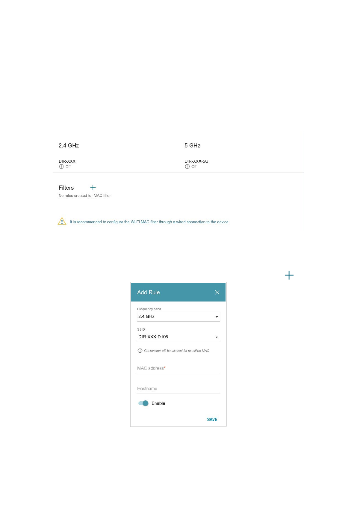
DIR-842V2 AC1200 Wi-Fi Gigabit Router
User Manual
Configuring via Web-based Interface
Page 144 of 200
MAC Filter
On the Functions / Wi-Fi / MAC Filter page, you can define a set of MAC addresses of devices
which will be allowed to access the WLAN, or define MAC addresses of devices which will not be
allowed to access the WLAN.
!
It is recommended to configure the Wi-Fi MAC filter through a wired connection to DIR-
842V2.
Figure 111. The page for configuring the MAC filter for the wireless network.
By default, the Wi-Fi MAC filter is not configured.
To configure the MAC filter, first you need to create rules (specify MAC addresses of devices for
which the specified filtering modes will be applied). To do this, click the ADD button ( ).
Figure 112. The window for adding a rule for the MAC filter.
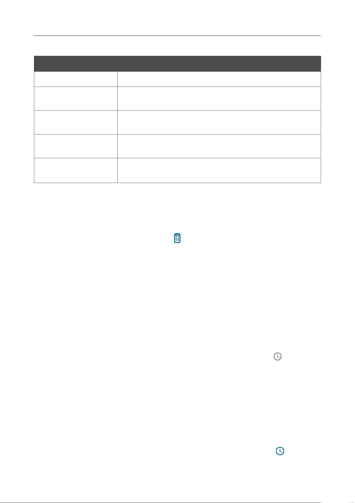
DIR-842V2 AC1200 Wi-Fi Gigabit Router
User Manual
Configuring via Web-based Interface
Page 145 of 200
You can specify the following parameters:
Parameter Description
Frequency band
From the drop-down list, select a band of the wireless network.
SSID
A wireless network to which the rule will be applied. Select the
needed value from the drop-down list.
MAC address
In the field, enter the MAC address of the device to which the
selected filtering mode will be applied.
Hostname
The name of the device for easier identification (optional). You can
specify any name.
Enable
If the switch is moved to the right, the rule is active.
Move the switch to the left to disable the rule.
When you have configured the parameters, click the SAVE button.
To edit the parameters of the existing rule, in the Filters section, left-click the needed rule. In the
opened window, change the settings and click the SAVE button.
To remove the rule from the page, in the Filters section, select the checkbox located to the left of
the relevant rule and click the DELETE button ( ).
After creating the rules you need to configure the filtering modes.
To open the basic or additional wireless network for the devices which MAC addresses are specified
on this page and to close the wireless network for all other devices, in the section corresponding to
the band (2.4 GHz or 5 GHz), left-click the line of the wireless network. In the opened window,
move the Enable MAC filter switch to the right. Upon that the MAC filter restrict mode drop-
down list will be displayed. Select the Allow value from the drop-down list and click the SAVE
button.
To close the wireless network for the devices which MAC addresses are specified on this page, select
the Deny value from the MAC filter restrict mode drop-down list and click the SAVE button.
To set a schedule for the MAC filter rule, click the Set Schedule button ( ) in the line
corresponding to this rule. In the opened window, you can create a new schedule (
see the Schedule
section, page 181) or use the existing one. Existing schedules are displayed in the Interval of
execution drop-down list in the simplified mode.
To enable the MAC filter rule at the time specified in the schedule and disable it at the other time,
select the Enable rule value from the Action drop-down list and click the SAVE button.
To disable the MAC filter rule at the time specified in the schedule and enable it at the other time,
select the Disable rule value from the Action drop-down list and click the SAVE button.
To change or delete the schedule for a rule, click the Select schedule button ( ) in the line
corresponding to this rule. In the opened window, change the parameters and click the SAVE button
or click the DELETE FROM SCHEDULE button.
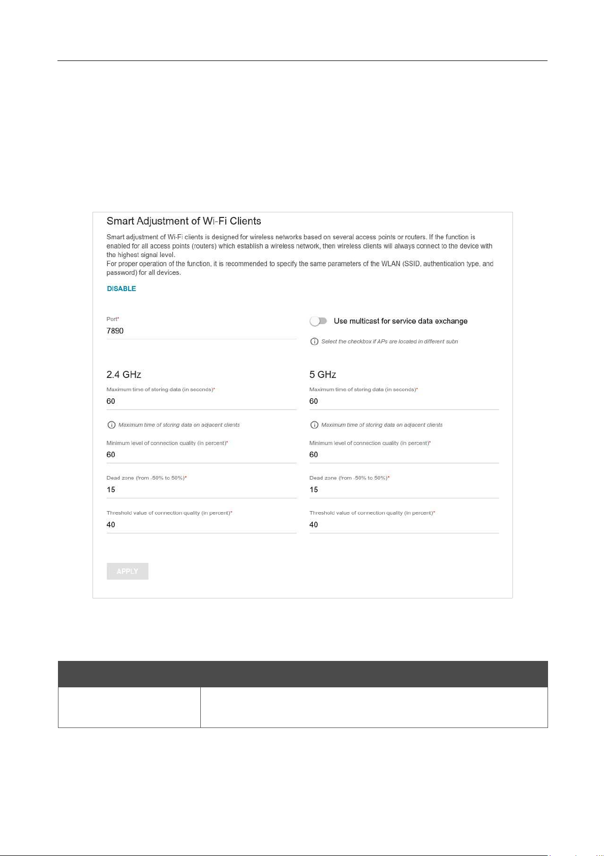
DIR-842V2 AC1200 Wi-Fi Gigabit Router
User Manual
Configuring via Web-based Interface
Page 146 of 200
Roaming
On the Functions / Wi-Fi / Roaming page, you can enable the function of smart adjustment of
Wi-Fi clients.
This function is designed for wireless networks based on several access points or routers. If the
function is enabled for all access points (routers) which establish a wireless network, then wireless
clients will always connect to the device with the highest signal level.
Figure 113. The Functions / Wi-Fi / Roaming page.
To enable the function, click the ENABLE button. Upon that the following settings are available on
the page.
Parameter Description
Port
The number of the port used for data exchange between access
points (routers).

DIR-842V2 AC1200 Wi-Fi Gigabit Router
User Manual
Configuring via Web-based Interface
Page 147 of 200
Parameter Description
Use multicast for
service data exchange
Move the switch to the right in order to use multicast traffic for
service
data exchange between access points (routers). This setting is needed
if the devices which support the smart adjustment function
are
located in different subnets. If the switch is moved to the right, the
Multicast TTL and Multicast group address fields are
displayed
on the page.
If the switch is moved to the left, broadcast traffic is used for service
data exchange.
Multicast TTL
Specify the TTL (Time to live) parameter value. The recommended
value is
4
.
Multicast group
address
Specify the address of the multicast group (from the subnet
239.255.0.0/16).
2.4 GHz / 5 GHz
Maximum time of
storing data
The maximum time period (in seconds) during which the access
point (router) stores data on the signal strength of the client located on
its coverage area.
Minimum level of
connection quality
The signal strength upon which the access point (router) starts
scanning other devices in order to find a device with a higher signal
level.
Dead zone
This parameter is used for calculation of the signal strength upon
which the smart adjustment function goes off. If the signal strength
provided by another device is less than the sum of the
Minimum
level of connection quality field value and the Dead zone
field
value, then the client disconnects from the access point (router). You
can specify the values from
-50%
to
+50%
.
Threshold value of
connection quality
The signal strength upon which the access point (router) disconnects
the client from its wireless network regardless of the signal levels of
other devices. This value should not be greater than the value specified
in the field Minimum level of connection quality.
After specifying the needed parameters, click the APPLY button.
To disable the function of smart adjustment of Wi-Fi clients, click the DISABLE button.
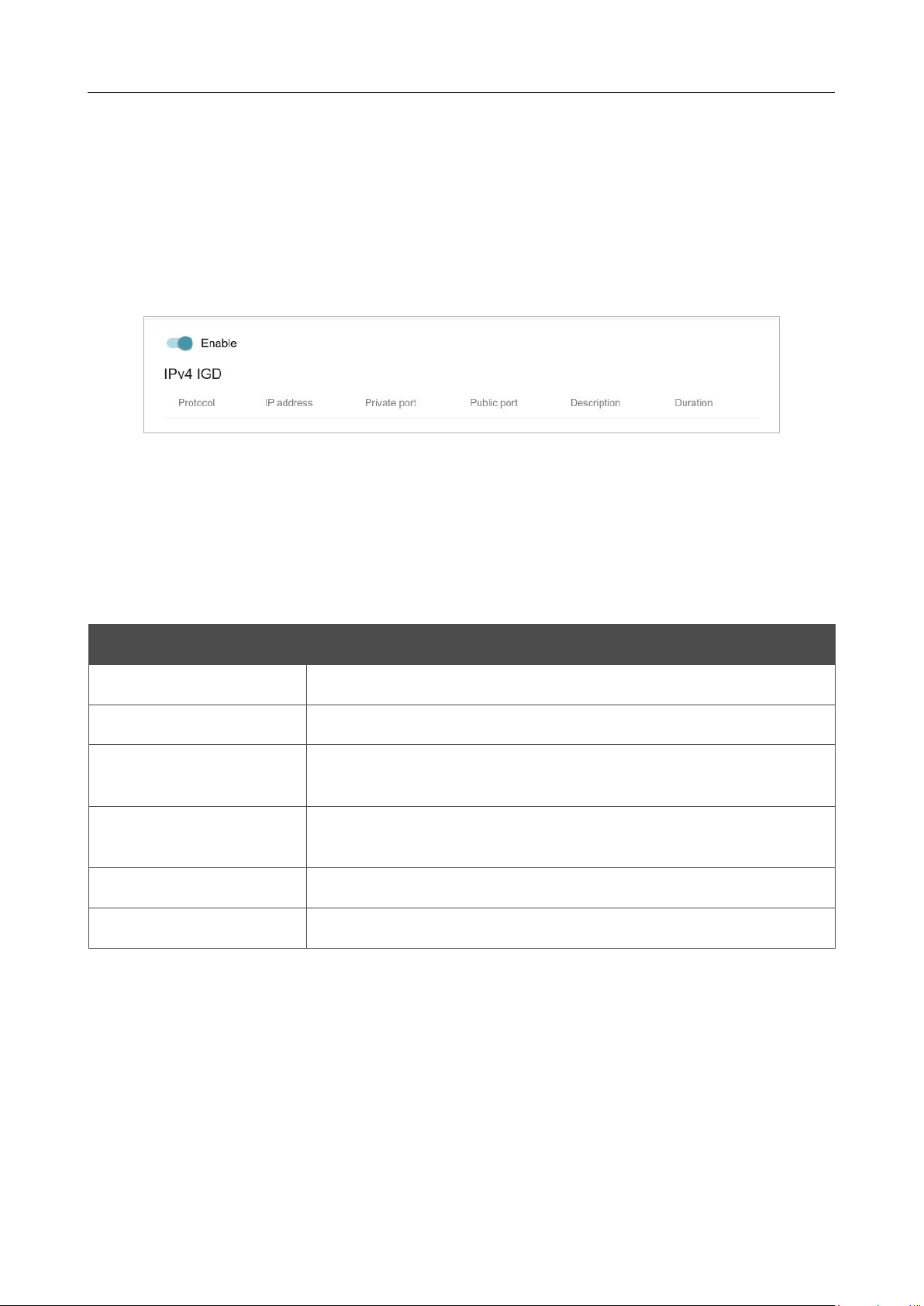
DIR-842V2 AC1200 Wi-Fi Gigabit Router
User Manual
Configuring via Web-based Interface
Page 148 of 200
Functions / Advanced
UPnP IGD
On the Functions / Advanced / UPnP IGD page, you can enable the UPnP IGD protocol. The
router uses the UPnP IGD protocol for automatic configuration of its parameters for network
applications requiring an incoming connection to the router.
Figure 114. The Functions / Advanced / UPnP IGD page.
If you want to manually specify all parameters needed for network applications, move the Enable
switch to the left. Then go to the Functions / Advanced / Virtual Servers page and specify
needed settings.
If you want to enable the UPnP IGD protocol in the router, move the Enable switch to the right.
When the protocol is enabled, the following parameters of the router are displayed on the page:
Parameter Description
Protocol
A protocol for network packet transmission.
IP address
The IP address of a client from the local area network.
Private port
A port of a client's IP address to which traffic is directed from a
public port of the router.
Public port
A public port of the router from which traffic is directed to a client's
IP address.
Description
Information transmitted by a client's network application.
Duration
The time period during which the UPnP IGD protocol has been used.
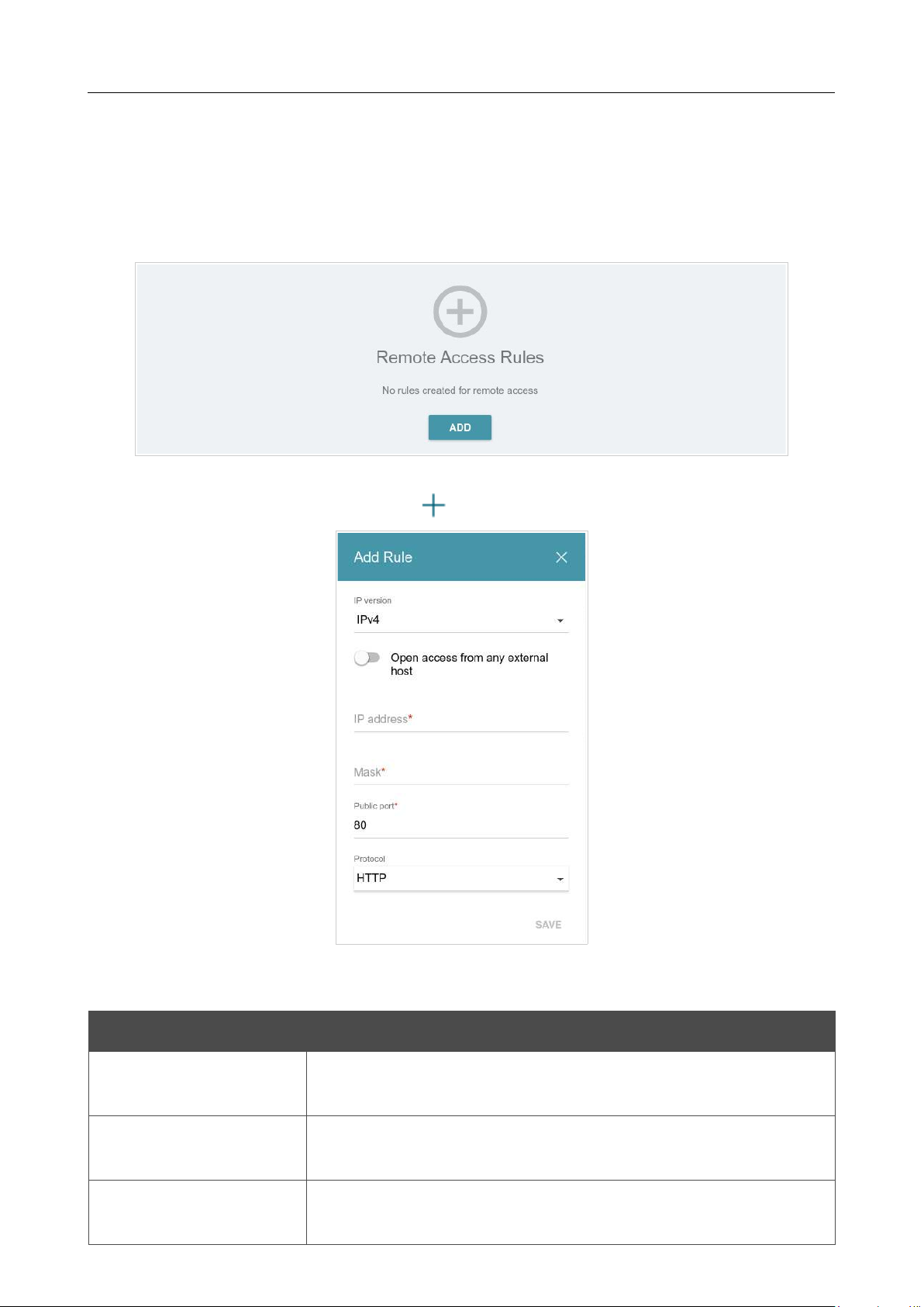
DIR-842V2 AC1200 Wi-Fi Gigabit Router
User Manual
Configuring via Web-based Interface
Page 149 of 200
Remote Access
On the Functions / Advanced / Remote Access page, you can configure access to the web-
based interface of the router. By default, the access from external networks to the router is closed. If
you need to allow access to the router from the external network, create relevant rules.
Figure 115. The Functions / Advanced / Remote Access page.
To create a new rule, click the ADD button ( ).
Figure 116. The window for adding a rule for remote management.
In the opened window, you can specify the following parameters:
Parameter Description
IP version
An IP version to which the rule will be applied. Select the relevant
value from the drop-down list.
Open access from any
external host
Move the switch to the right to allow access to the router for any
host. Upon that the IP address and Mask fields are not displayed.
IP address
A host or a subnet to which the rule is applied. You can specify an
IPv4 or IPv6 address.

DIR-842V2 AC1200 Wi-Fi Gigabit Router
User Manual
Configuring via Web-based Interface
Page 150 of 200
Parameter Description
Mask
For the IPv4-based network only.
The mask of the subnet.
Public port
For the IPv4-based network only.
An external port of the router. You can specify only one port.
Protocol
The protocol available for remote management of the router.
After specifying the needed parameters, click the SAVE button.
To edit a rule for remote access, left-click the relevant rule. In the opened window, change the
needed parameters and click the SAVE button.
To remove a rule for remote access, select the checkbox located to the left of the relevant line in the
table and click the DELETE button ( ).
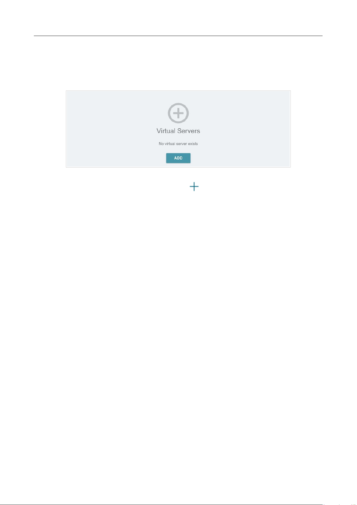
DIR-842V2 AC1200 Wi-Fi Gigabit Router
User Manual
Configuring via Web-based Interface
Page 151 of 200
Virtual Servers
On the Functions / Advanced / Virtual Servers page, you can create virtual servers for
redirecting incoming Internet traffic to a specified IP address in the local area network.
Figure 117. The Functions / Advanced / Virtual Servers page.
To create a new virtual server, click the ADD button ( ).
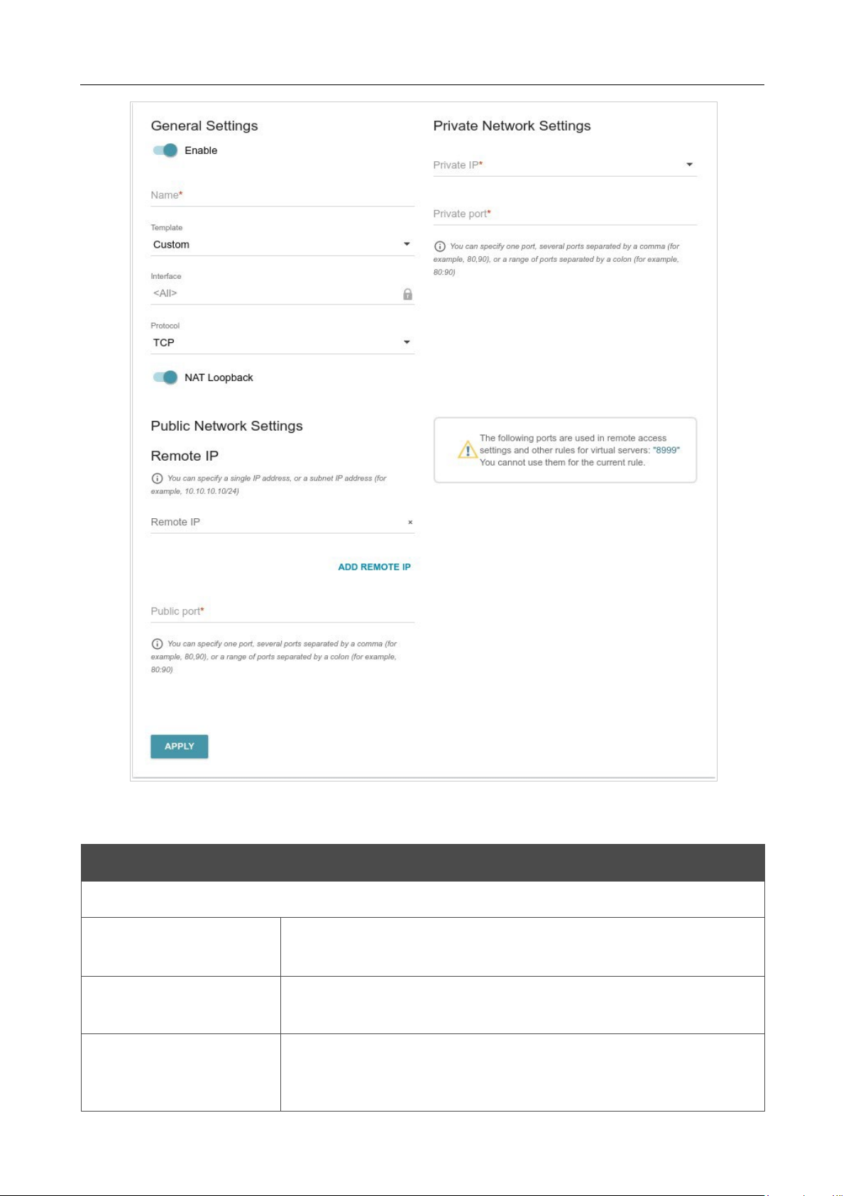
DIR-842V2 AC1200 Wi-Fi Gigabit Router
User Manual
Configuring via Web-based Interface
Page 152 of 200
Figure 118. The page for adding a virtual server.
You can specify the following parameters:
Parameter Description
General Settings
Enable
Move the switch to the right to enable the server.
Move the switch to the left to disable the server.
Name
A name for the virtual server for easier identification. You can
specify any name.
Template
Select a virtual server template from the drop-
down list, or select
Custom to specify all parameters of the new virtual server
manually.

DIR-842V2 AC1200 Wi-Fi Gigabit Router
User Manual
Configuring via Web-based Interface
Page 153 of 200
Parameter Description
Interface
A WAN connection to which this virtual server will be assigned.
Protocol
A protocol that will be used by the new virtual server. Select a value
from the drop-down list.
NAT Loopback
Move the switch to the right in order to let the users of the router's
LAN access the local server using the external IP address of the
router
or its DDNS name (if a DDNS service is configured). Users
from the
external network access the router using the same address (or
DDNS
name).
Public Network Settings
Remote IP
Enter the IP address of the server from the external network.
To add one more IP address, click the ADD REMOTE IP button and
enter the address in the displayed line.
To remove the IP address, click the Delete icon ( ) in the line of
the address.
Public port
A port of the router from which traffic is directed to the IP address
specified in the Private IP field in the
Private Network Settings
section. You can specify one port or several ports separated by a
comma.
Private Network Settings
Private IP
The IP address of the server from the local area network.
To choose
a device connected to the router's LAN at the moment, select the
relevant value from the drop-down list (the field will be filled in
automatically).
Private port
A port of the IP address specified in the Private IP
field to which
traffic is directed from the Public port
. You can specify one port or
several ports separated by a comma.
Click the APPLY button.
To edit the parameters of an existing server, select the relevant line in the table. On the opened page,
change the needed parameters and click the APPLY button.
To remove a server, select the checkbox located to the left of the relevant line of the table and click
the DELETE button ( ). Also you can remove a server on the editing page.
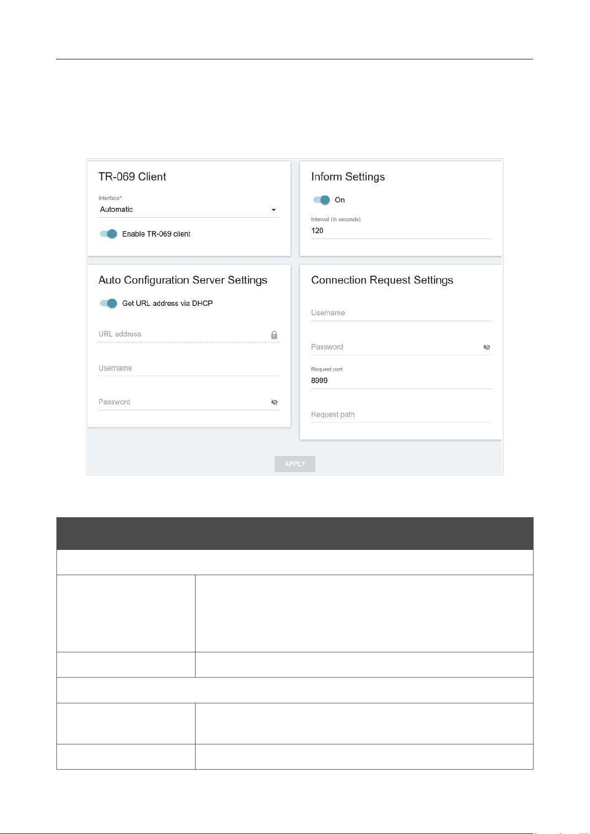
DIR-842V2 AC1200 Wi-Fi Gigabit Router
User Manual
Configuring via Web-based Interface
Page 154 of 200
TR-069 Client
On the Functions / Advanced / TR-069 Client page, you can configure the router for
communication with a remote Auto Configuration Server (ACS).
The TR-069 client is used for remote monitoring and management of the device.
Figure 119. The page for configuring the TR-069 client.
You can specify the following parameters:
Parameter Description
TR-069 Client
Interface
The interface which the router uses for communication with the ACS.
Leave the Automatic value to let the device select the interface
basing on the routing table or select another value if required by your
ISP.
Enable TR-069 client
Move the switch to the right to enable the TR-069 client.
Inform Settings
On
Move the switch to the right so the router may send reports (data on
the device and network statistics) to the ACS.
Interval
Specify the time period (in seconds) between sending reports.

DIR-842V2 AC1200 Wi-Fi Gigabit Router
User Manual
Configuring via Web-based Interface
Page 155 of 200
Parameter Description
Auto Configuration Server Settings
Get URL address via
DHCP
If the switch is moved to the right, the router obtains the URL address
of the ACS upon establishing the Dynamic IP type connection.
If you need to specify the URL address manually, move the switch
to
the left and enter the needed value in the URL address field.
URL address
The URL address of the ACS provided by the ISP.
Username
The username to connect to the ACS.
Password
The password to connect to the ACS.
Connection Request Settings
Username
The username used by the ACS to transfer a connection request to
the router.
Password
The password used by the ACS.
Request port
The port used by the ACS. By default, the port 8999 is specified.
Request path
The path used by the ACS.
When you have configured the parameters, click the APPLY button.
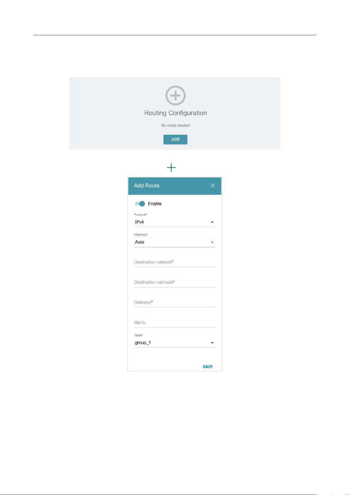
DIR-842V2 AC1200 Wi-Fi Gigabit Router
User Manual
Configuring via Web-based Interface
Page 156 of 200
Static Route
On the Functions / Advanced / Static Route page, you can specify static (fixed) routes.
Figure 120. The Functions / Advanced / Static Route page.
To specify a new route, click the ADD button ( ).
Figure 121. The window for adding a new route.

DIR-842V2 AC1200 Wi-Fi Gigabit Router
User Manual
Configuring via Web-based Interface
Page 157 of 200
In the opened window, you can specify the following parameters:
Parameter Description
Enable
Move the switch to the right to enable the route.
Move the switch to the left to disable the route.
Protocol
An IP version.
Interface
From the drop-down list, select an interface (connection) through
which the device will communicate with the remote network. If you
have selected the Auto value, the router itself sets the interface
according to the data on the existing dynamic routes.
Destination network
A remote network which can be accessed with help of this route.
You can specify an IPv4 or IPv6 address.
The format of a host IPv6 address is 2001:db8:1234::1, the
format of a subnet IPv6 address is
2001:db8:1234::/64
.
Destination netmask
For IPv4 protocol only.
The remote network mask.
Gateway
An IP address through which the destination network can be
accessed.
Metric
A metric for the route. The lower the value, the higher is the route
priority. Optional.
Table
From the drop-down list, select a routing table for the route.
• group_1 table is used to route user traffic.
• main table is used to route management traffic from
internal system services of the router.
After specifying the needed parameters, click the SAVE button.
To edit an existing route, select a relevant line of the table. In the opened window, change the
needed parameters and click the SAVE button.
To remove an existing route, select the checkbox located to the left of the relevant line in the table
and click the DELETE button ( ).
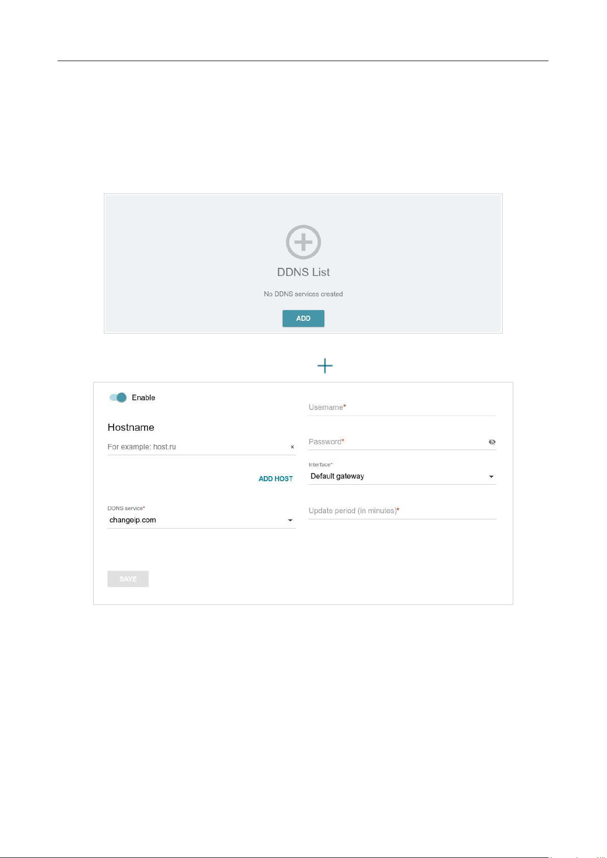
DIR-842V2 AC1200 Wi-Fi Gigabit Router
User Manual
Configuring via Web-based Interface
Page 158 of 200
Dynamic DNS
On the Functions / Advanced / Dynamic DNS page, ou can configure the router to use one or
several DDNS services.
A DDNS service allows associating a domain name with dynamic IP addresses. In order to use a
service, it is necessary to register a domain name on the web site of your DDNS provider.
Figure 122. The Functions / Advanced / Dynamic DNS page.
To add a new DDNS service, click the ADD button ( ).
Figure 123. The page for adding a DDNS service.

DIR-842V2 AC1200 Wi-Fi Gigabit Router
User Manual
Configuring via Web-based Interface
Page 159 of 200
On the opened page, you can specify the following parameters:
Parameter Description
Enable
Move the switch to the right to enable DDNS.
Move the switch to the left to disable DDNS.
Hostname
Enter the full domain name registered at your DDNS provider.
If you want to use another domain name of this DDNS provider,
click
the ADD HOST button, and in the line displayed, enter the
needed
value.
To remove a domain name, click the Delete icon ( ) in the line of the
name.
DDNS service
Select the DDNS provider from the drop-down list. If your provider
is not in the list, select the Custom provider value and fill in the
fields displayed on the page. Specify the DDNS provider name in
the
Name field, the domain name of the provider's server in the Server
field, and the location of settings in the Path field.
Username
The username to authorize for your DDNS provider.
Password
The password to authorize for your DDNS provider.
Click the
Show icon ( ) to display the entered password.
Interface
From the drop-down list, select a WAN connection which will be
used for DDNS, or leave the Default gateway value.
Update period
An interval (in minutes) between sending data on the router's
external IP address to the relevant DDNS service.
After specifying the needed parameters, click the SAVE button.
To specify other parameters for a DDNS service, select the relevant line in the table. On the opened
page, change the needed parameters and click the SAVE button.
To remove settings for a DDNS service, select the checkbox located to the left of the relevant line in
the table and click the DELETE button ( ).
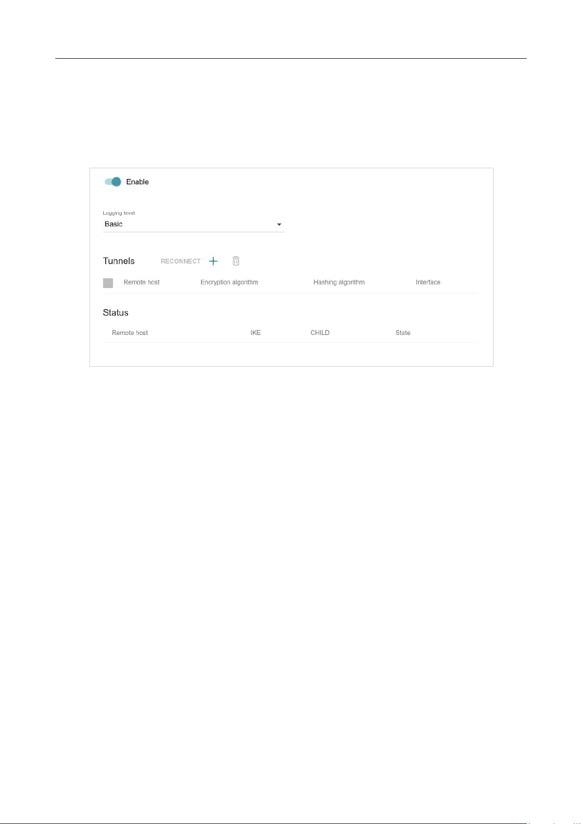
DIR-842V2 AC1200 Wi-Fi Gigabit Router
User Manual
Configuring via Web-based Interface
Page 160 of 200
IPsec
On the Functions / Advanced / IPsec page, you can configure VPN tunnels based on IPsec
protocol.
IPsec is a protocol suite for securing IP communications.
Figure 124. The Functions / Advanced / IPsec page.
To allow IPsec tunnels, move the Enable switch to the right. Upon that the Tunnels and Status
sections and the Logging level drop-down list are displayed on the page.
In the Status section, the current state of an existing tunnel is displayed.
From the Logging level drop-down list, select a detail level of messages recorded to the system log
or leave the value specified by default. The Basic value is recommended to establish an IPsec tunnel
faster. To view the log, go to the Management / System Log page (see the System Log section,
page 168).
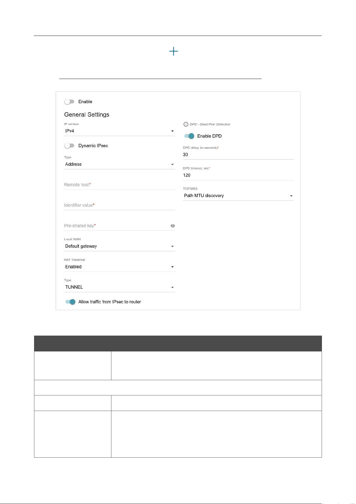
DIR-842V2 AC1200 Wi-Fi Gigabit Router
User Manual
Configuring via Web-based Interface
Page 161 of 200
To create a new tunnel, click the ADD button ( ) in the Tunnels section.
!
Setting for both devices which establish the tunnel should be the same.
Figure 125. The page for adding an IPsec tunnel. The General Settings section.
You can specify the following parameters:
Parameter Description
Enable
Move the switch to the right to enable the tunnel.
Move the switch to the left to disable the tunnel.
General Settings
IP version
An IP version.
Dynamic IPsec
Move the switch to the right to allow a remote host with any public IP
address to connect to the router via IPsec protocol. Such a setting can
be specified for one IPsec tunnel only. Connection requests via this
tunnel can be sent by a remote host only.

DIR-842V2 AC1200 Wi-Fi Gigabit Router
User Manual
Configuring via Web-based Interface
Page 162 of 200
Parameter Description
Type
Select an identification method for the remote host (router) from the
drop-down list:
• Address: The remote host is identified by its IP address.
• FQDN: The remote host is identified by its domain name.
The drop-down list is displayed if the Dynamic IPsec switch is
moved to the left.
Remote host
Enter the remote subnet VPN gateway IP address if the Address
value is selected from the Type drop-down list.
Enter the remote subnet VPN gateway domain name if the FQDN
value is selected from the Type drop-down list.
The field is available for editing if the Dynamic IPsec switch is
moved to the left.
Identifier value
Specify a unique name of the tunnel.
Pre-shared key
A PSK key for mutual authentication of the parties.
Click the Show
icon ( ) to display the entered key.
Local WAN
A WAN connection through which the tunnel will pass. Select a value
from the drop-down list.
• Interface: When this value is selected, the Interface drop-
down list is displayed. Select an existing WAN connection
from
the list.
• Default gateway: When this value is selected, the router uses
the default WAN connection.
NAT Traversal
The NAT Traversal function allows VPN traffic to pass through the
NAT-enabled device. DIR-842V2 allows to forcibly encapsulate VPN
traffic in UDP packets for passing through a remote device regardless
of whether it supports address translation.
If you need to enable forced encapsulation of VPN traffic, select the
Enabled value.
If you need to disable forced encapsulation of VPN traffic, select the
Disabled value.

DIR-842V2 AC1200 Wi-Fi Gigabit Router
User Manual
Configuring via Web-based Interface
Page 163 of 200
Parameter Description
Type
An operation mode of the IPsec tunnel. Select a value from the drop-
down list.
• TUNNEL: As a rule, it is used to create a secure connection to
remote networks. In this mode, the source IP packet is fully
encrypted and added to a new IP packet and data transfer is
based on the header of the new IP packet.
• TRANSPORT: As a rule, it is used to encrypt data stream
within one network. In this mode, only the content of the
source
IP packet is encrypted, its header remains unchanged and
data
transfer is based on the source header.
Allow traffic from
IPsec to router
Move the switch to the left to deny access to your router from the
remote subnet via IPsec.
Enable DPD
Move the switch to the right to enable using DPD protocol for this
tunnel. Such a setting allows to check the status of the remote host: if
encrypted packets exchange between the router and the remote host
breaks down, the router starts sending DPD messages to the remote
host.
If the switch is moved to to the left, the DPD delay and DPD timeout
fields are not available for editing.
DPD delay
A time period (in seconds) between DPD messages. By default, the
value
30
is specified.
DPD timeout
A waiting period for the response to a DPD message (in seconds). If
the
host does not answer in the specified time, the router breaks down the
tunnel connection, updates information on it, and tries to reestablish the
connection. By default, the value
120
is specified.
TCP MSS
Maximum Segment Size of a TCP packet. This parameter influences
the
size of a TCP packet which will be sent from the remote host to the
router.
If the Manual value is selected, you can specify the value of this
parameter for each subnet of the tunnel in the MTU field. The field is
displayed in the window for adding a subnet in the Tunneled
Networks section.
If the Path MTU discovery value is selected, the parameter will be
configured automatically for all created subnets.
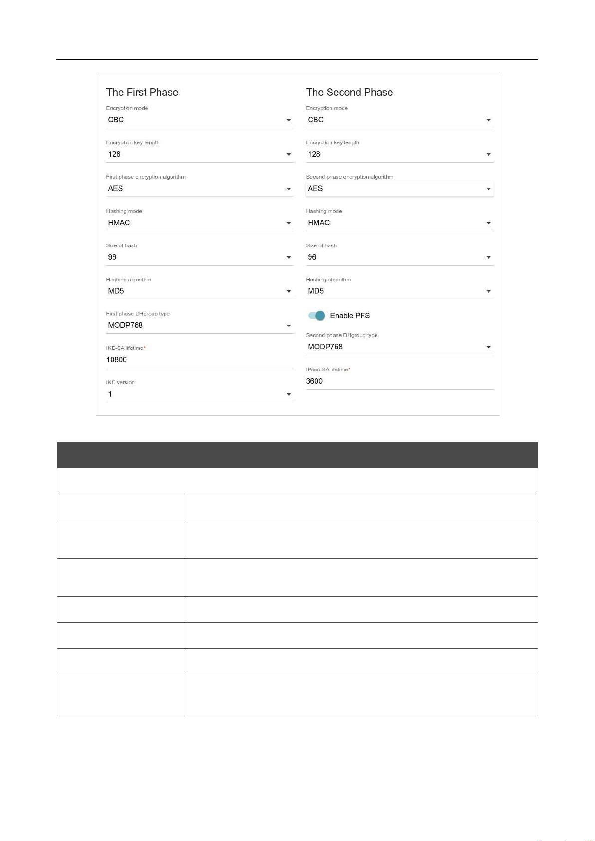
DIR-842V2 AC1200 Wi-Fi Gigabit Router
User Manual
Configuring via Web-based Interface
Page 164 of 200
Figure 126. The page for adding an IPsec tunnel. The First Phase / The Second Phase sections.
Parameter Description
The First Phase
Encryption mode
Select an encryption mode from the drop-down list.
Encryption key
length
The encryption key length in bits.
First phase
encryption algorithm
Select an available encryption algorithm from the drop-down list.
Hashing mode
Select a hashing mode from the drop-down list.
Size of hash
The length of the hash in bits.
Hashing algorithm
Select a hashing algorithm from the drop-down list.
First phase DHgroup
type
A Diffie-Hellman key group for Phase 1. Select a value from the drop-
down list.

DIR-842V2 AC1200 Wi-Fi Gigabit Router
User Manual
Configuring via Web-based Interface
Page 165 of 200
Parameter Description
IKE-SA lifetime
The lifetime of IKE-SA keys in seconds. After the specified period it is
required to renegotiate the keys. The value specified in this field
should
be greater than the value specified in the IPsec-SA lifetime field.
IKE version
IKE (Internet Key Exchange) is a protocol of keys exchange between
two hosts of VPN connections. Select a version of the protocol from
the
drop-down list.
The Second Phase
Encryption mode
Select an encryption mode from the drop-down list.
Encryption key
length
The encryption key length in bits.
Second phase
encryption algorithm
Select an available encryption algorithm from the drop-down list.
Hashing mode
Select a hashing mode from the drop-down list.
Size of hash
The length of the hash in bits.
Hashing algorithm
Select a hashing algorithm from the drop-down list.
Enable PFS
Move the switch to the right to enable the PFS option (Perfect Forward
Secrecy). If the switch is moved to the right, a new encryption key
exchange will be used for Phase 2. This option
enhances the security
level of data transfer, but increases the load on DIR-842V2.
Second phase
DHgroup type
A Diffie-Hellman key group for Phase 2. Select a value from the drop-
down list. The drop-down list is available if the Enable PFS switch
is moved to the right.
IPsec-SA lifetime
The lifetime of Phase 2 keys in seconds. After the specified period it is
required to renegotiate the keys. The value specified in this field should
be greater than zero.
To specify IP addresses of local and remote subnets for this tunnel, click the ADD button ( ) in
the Tunneled Networks section.
If the IPsec tunnel operates over IKEv1 (1 is selected from the IKE version list in the The First
Phase section), you can create only one subnet.
If the IPsec tunnel operates over IKEv2 (2 is selected from the IKE version list in the The First
Phase section), you can create several subnets.
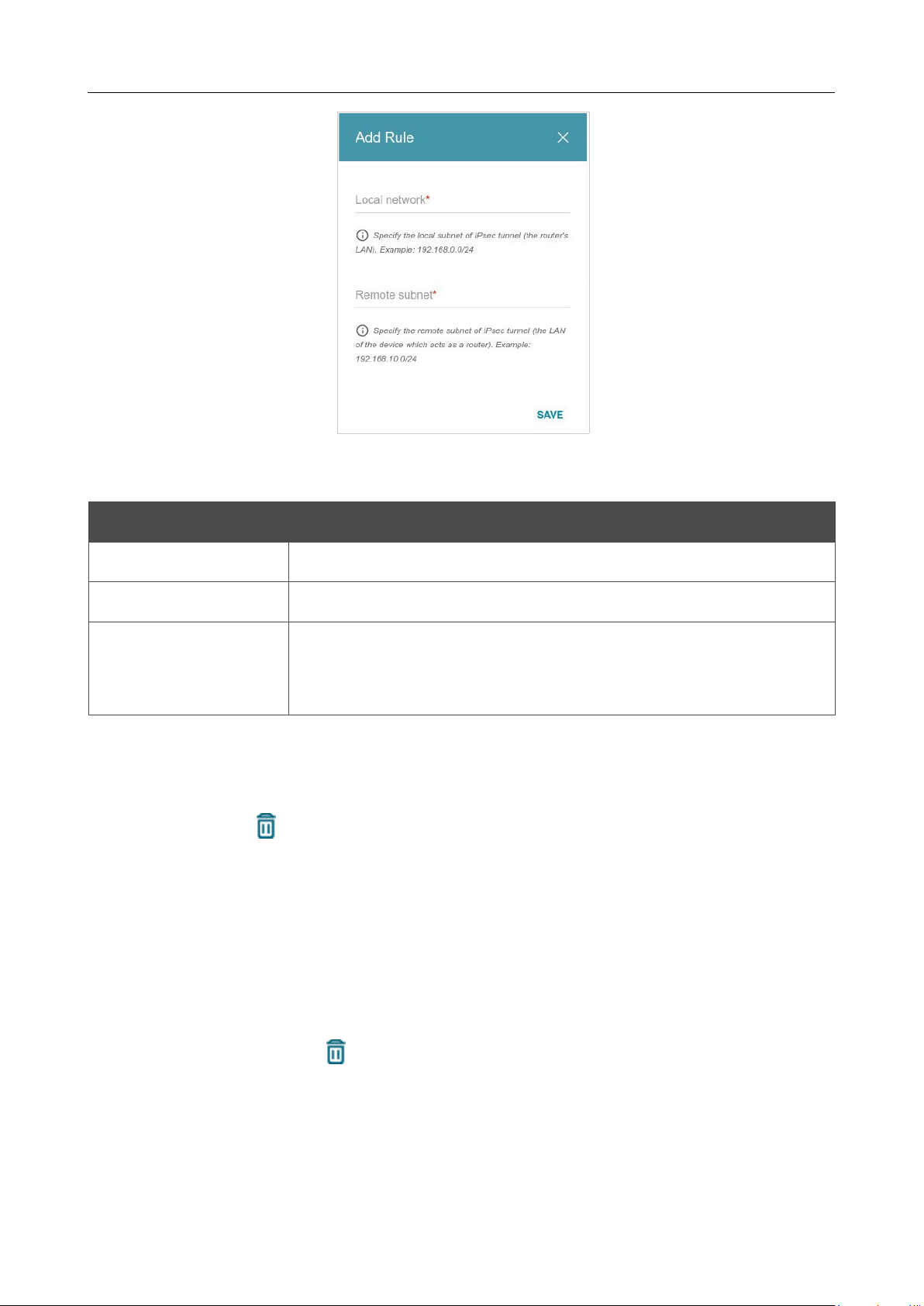
DIR-842V2 AC1200 Wi-Fi Gigabit Router
User Manual
Configuring via Web-based Interface
Page 166 of 200
Figure 127. The page for adding an IPsec tunnel. The window for adding a tunneled network.
In the opened window, you can specify the following parameters:
Parameter Description
Local network
A local subnet IP address and mask.
Remote subnet
A remote subnet IP address and mask.
MTU
The maximum size (in bytes) of a non-fragmented packet. The field is
displayed when the Manual value is selected from the TCP MSS drop-
down list in the General Settings section.
To edit fields in the Tunneled Networks section, select the relevant line in the table. In the
opened window, change the needed parameters and click the SAVE button.
To remove a subnet, select the checkbox located to the left of the relevant line in the table and click
the DELETE button ( ). Also you can remove a subnet in the editing window.
After configuring all needed settings for the IPsec tunnel, click the APPLY button.
To edit the parameters of an existing tunnel, in the Tunnels section, select the relevant tunnel in the
table. On the opened page, change the needed parameters and click the APPLY button.
To disconnect an existing tunnel and establish it again, select the checkbox located to the left of the
relevant line in the table and click the RECONNECT button.
To remove an existing tunnel, select the checkbox located to the left of the relevant line in the table
and click the DELETE button ( ). Also you can remove a tunnel on the editing page.
To disable VPN tunnels based on IPsec protocol, move the Enable switch to the left.
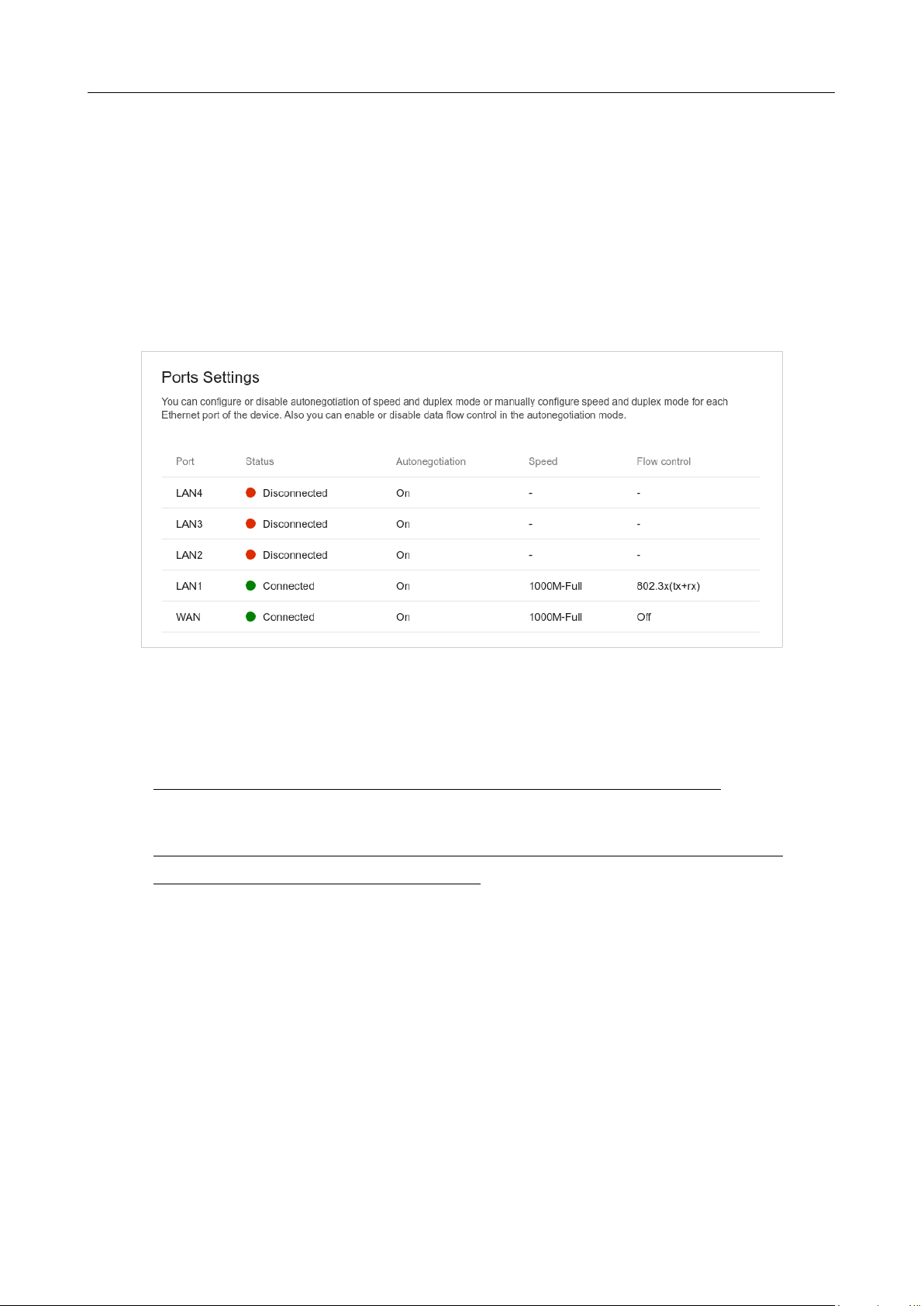
DIR-842V2 AC1200 Wi-Fi Gigabit Router
User Manual
Configuring via Web-based Interface
Page 167 of 200
Ports Settings
On the Functions / Advanced / Ports Settings page, you can configure or disable
autonegotiation of speed and duplex mode or manually configure speed and duplex mode for each
Ethernet port of the router.
Also you can enable or disable data flow control in the autonegotiation mode. This function is used
for equal load balancing in ISPs' networks. Contact your ISP to clarify if this function needs to be
enabled.
Figure 128. The Functions / Advanced / Ports Settings page.
In order to configure autonegotiation or configure speed and duplex mode manually for an Ethernet
port, select it in the table.
!
Autonegotiation should be enabled for both devices connected to each other.
!
When autonegotiation is disabled, speed and duplex mode settings for both devices
connected to each other should be the same.
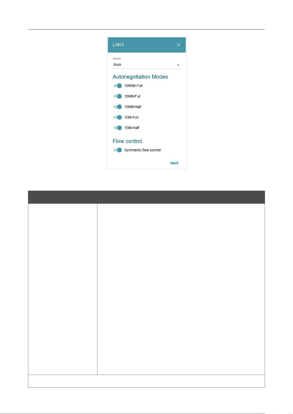
DIR-842V2 AC1200 Wi-Fi Gigabit Router
User Manual
Configuring via Web-based Interface
Page 168 of 200
Figure 129. The window for changing the settings of the router's port.
In the opened window, specify the needed parameters:
Parameter Description
Speed
Data transfer mode.
Select the A
uto value to enable autonegotiation. When this value is
selected, the Autonegotiation Modes and Flow control
sections
are displayed.
Select the 10M-Half, 10M-Full, 100M-Half, or 100M-Full
value
to manually configure speed and duplex mode for the selected port:
•
10M-Half: Data transfer in just one direction at a time (data
can be either sent or received) at the maximum possible
rate
of up to 10Mbps.
• 10M-Full:
Data transfer in two directions simultaneously
(data can be sent and received at the same time) at
the
maximum possible rate of up to 10Mbps.
•
100M-Half: Data transfer in just one direction at a time
(data
can be either sent or received) at the maximum possible
rate
of up to 100Mbps.
• 100M-Full:
Data transfer in two directions simultaneously
(data can be sent and received at the same time) at
the
maximum possible rate of up to 100Mbps.
Autonegotiation Modes

DIR-842V2 AC1200 Wi-Fi Gigabit Router
User Manual
Configuring via Web-based Interface
Page 169 of 200
To enable the needed data transfer modes, move relevant switches to the right.

DIR-842V2 AC1200 Wi-Fi Gigabit Router
User Manual
Configuring via Web-based Interface
Page 170 of 200
Parameter Description
Flow control
Symmetric flow control
Move the switch to the right to enable the flow control function for
the port.
Move the switch to the left to disable the flow control function for
the port.
After specifying the needed parameters, click the SAVE button.
If in the future you
need to edit the parameters of the router's port, select the port in the table. In the
opened window, change the needed parameters and click the SAVE button.
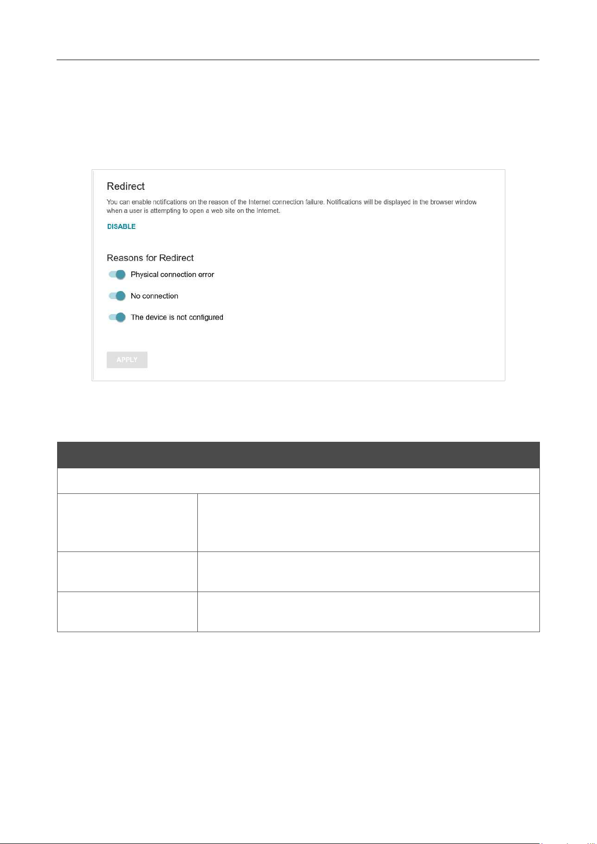
DIR-842V2 AC1200 Wi-Fi Gigabit Router
User Manual
Configuring via Web-based Interface
Page 171 of 200
Redirect
On the Functions/ Advanced / Redirect page, you can enable notifications on the reason of the
Internet connection failure. Notifications will be displayed in the browser window when a user is
attempting to open a web site on the Internet.
Figure 130. The Functions / Advanced / Redirect page.
To configure notifications, click the ENABLE button. Then, in the Reasons for Redirect
section, move the needed switches to the right.
Parameter Description
Reasons for Redirect
Physical connection
error
Notifications in case of physical connection problems (the ISP's
cable
is not connected, an additional device needed to access the
Internet is
not connected).
No connection
Notifications in case of problems of the default WAN connection
(authorization error, the IPS's server does not respond, etc.).
The device is not
configured
Notifications in case when the device works with default settings.
When you have configured the parameters, click the APPLY button.
To disable notifications, click the DISABLE button.
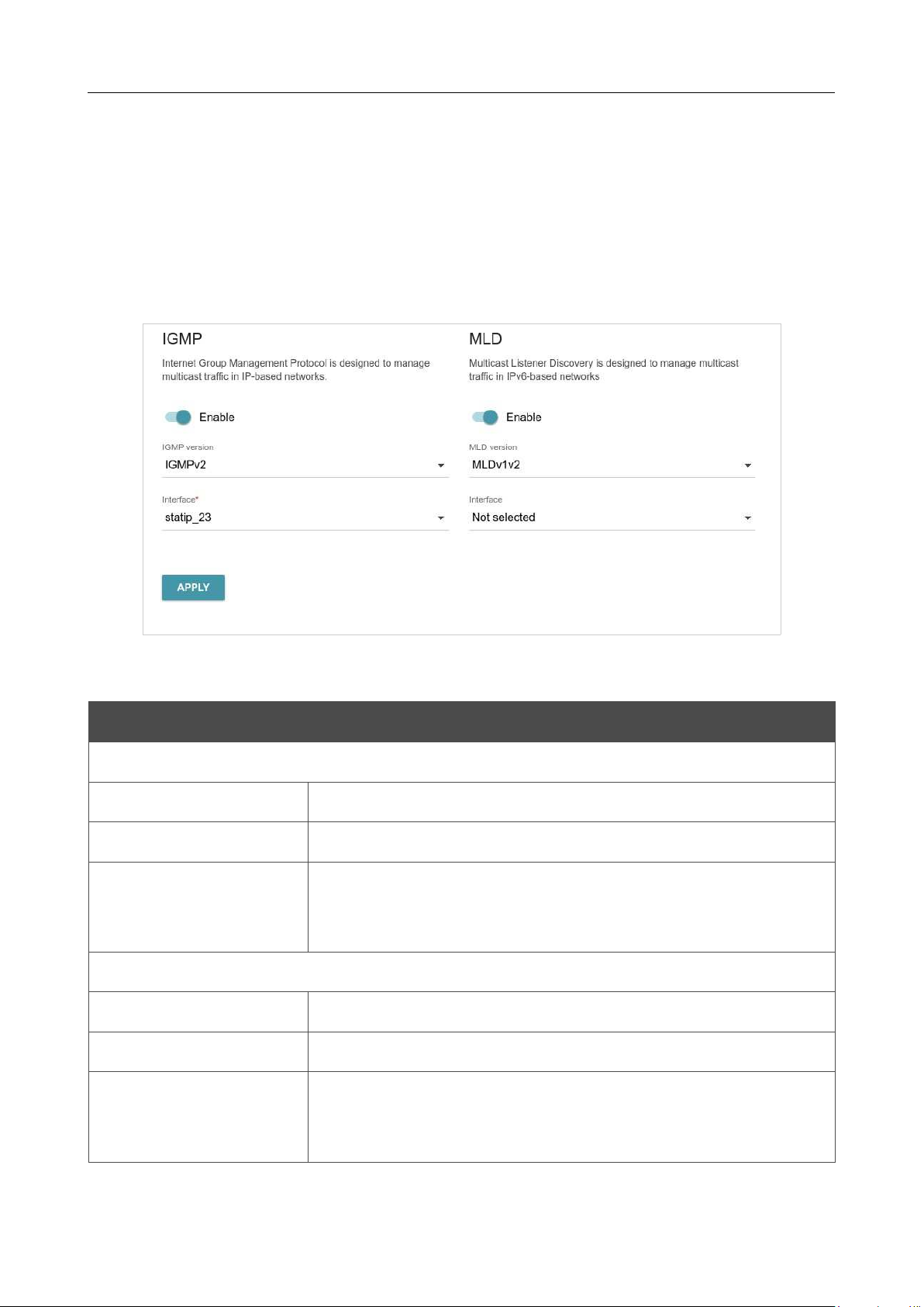
DIR-842V2 AC1200 Wi-Fi Gigabit Router
User Manual
Configuring via Web-based Interface
Page 172 of 200
IGMP/MLD
On the Functions/ Advanced / IGMP/MLD page, you can allow the router to use IGMP and MLD
and specify needed settings.
IGMP and MLD are used for managing multicast traffic (transferring data to a group of destinations)
in IPv4 and IPv6 networks correspondingly. These protocols allow using network resources for some
applications, e.g., for streaming video, more efficiently.
Figure 131. The Functions / Advanced / IGMP/MLD page.
The following elements are available on the page:
Parameter Description
IGMP
Enable
Move the switch to the right to enable IGMP.
IGMP version
Select a version of IGMP from the drop-down list.
Interface
From the drop-
down list, select a connection of the Dynamic IPv4 or
Static IPv4 type for which you need to allow multicast traffic (e.g.
streaming video).
MLD
Enable
Move the switch to the right to enable MLD.
MLD version
Select a version of MLD from the drop-down list.
Interface
From the drop-
down list, select a connection of the Dynamic IPv6 or
Static IPv6 type for which you need to allow multicast traffic (e.g.
streaming video).
After specifying the needed parameters, click the APPLY button.
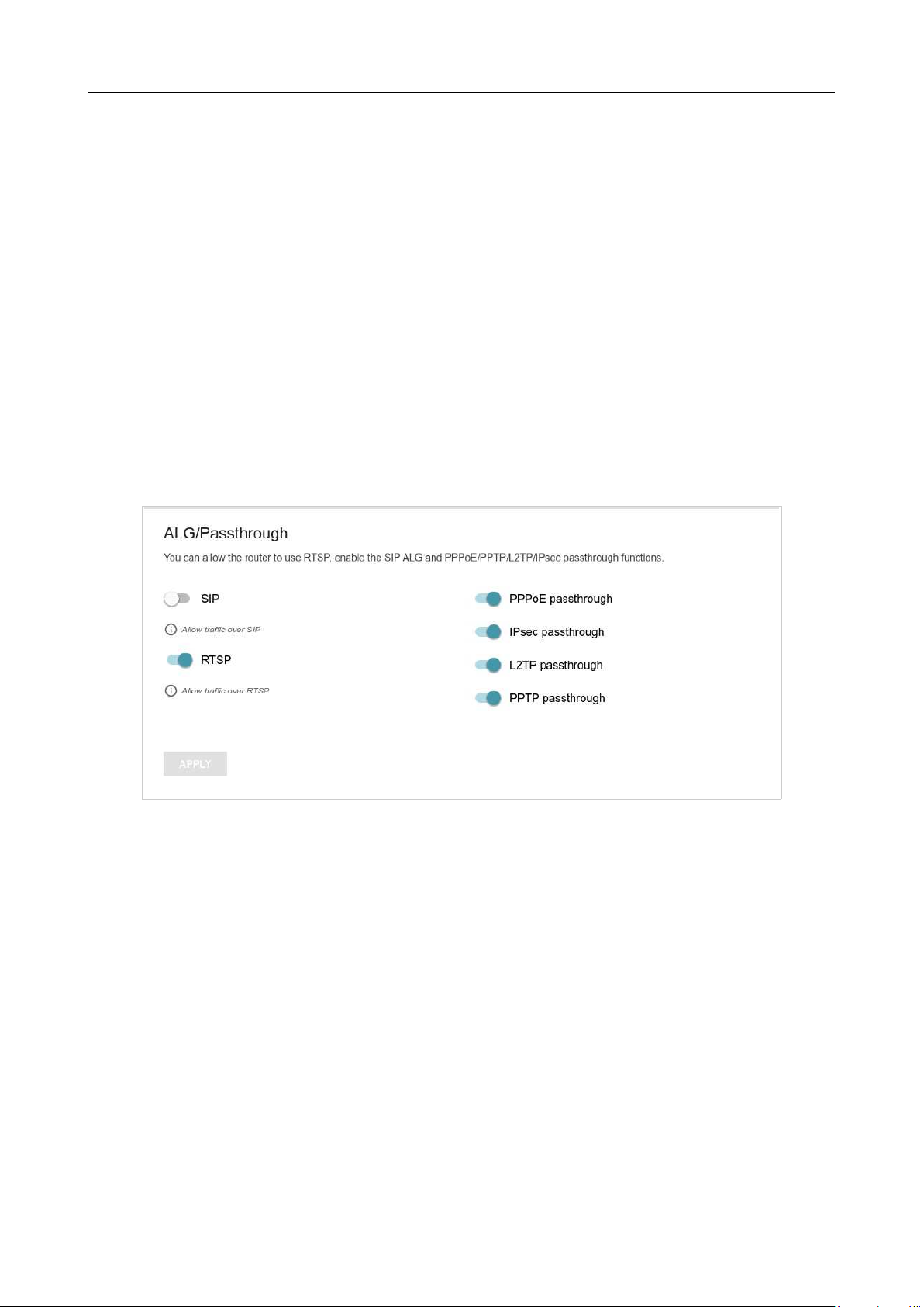
DIR-842V2 AC1200 Wi-Fi Gigabit Router
User Manual
Configuring via Web-based Interface
Page 173 of 200
AL
G
/
Pa
sst
h
r
o
u
gh
On the Functions/ Advanced / ALG/Passthrough page, you can allow the router to use RTSP,
enable the SIP ALG and PPPoE/PPTP/L2TP/IPsec pass through functions.
SIP is used for creating, modifying, and terminating communication sessions. This protocol allows
telephone calls via the Internet.
RTSP is used for real-time streaming multimedia data delivery. This protocol allows some
applications to receive streaming audio/video from the Internet.
The PPPoE pass through function allows PPPoE clients of computers from your LAN to connect to
the Internet through connections of the router.
The PPTP pass through, L2TP pass through and IPsec pass through functions allow VPN PPTP, L2TP
and IPsec traffic to pass through the router so that clients from your LAN can establish relevant
connections with remote networks.
Figure 132. The Functions / Advanced / ALG/Passthrough page.

DIR-842V2 AC1200 Wi-Fi Gigabit Router
User Manual
Configuring via Web-based Interface
Page 174 of 200
The following elements are available on the page:
Parameter Description
SIP
Move the switch to the right to enable SIP. Such a setting allows
using
the SIP ALG function. This function allows VoIP traffic to pass
through the NAT-enabled router.6
RTSP
Move the switch to the right to enable RTSP. Such a setting allows
managing media stream: fast forward streaming audio/video, pause
and start it.
PPPoE pass through
Move the switch to the right to enable the PPPoE pass through
function.
IPsec pass through
Move the switch to the right to enable the IPsec pass through
function.
L2TP pass through
Move the switch to the right to enable the L2TP pass through
function.
PPTP pass through
Move the switch to the right to enable the PPTP pass through
function.
After specifying the needed parameters, click the APPLY button.
6 On the Settings / Internet / WAN page, create a WAN connection, move the SIP switch to the right on the
Functions / Advanced / ALG/Passthrough page, connect an Ethernet cable between a LAN port of the router
and the IP phone. Specify SIP parameters on the IP phone and configure it to obtain an IP address automatically (as

DIR-842V2 AC1200 Wi-Fi Gigabit Router
User Manual
Configuring via Web-based Interface
Page 175 of 200
DHCP client).
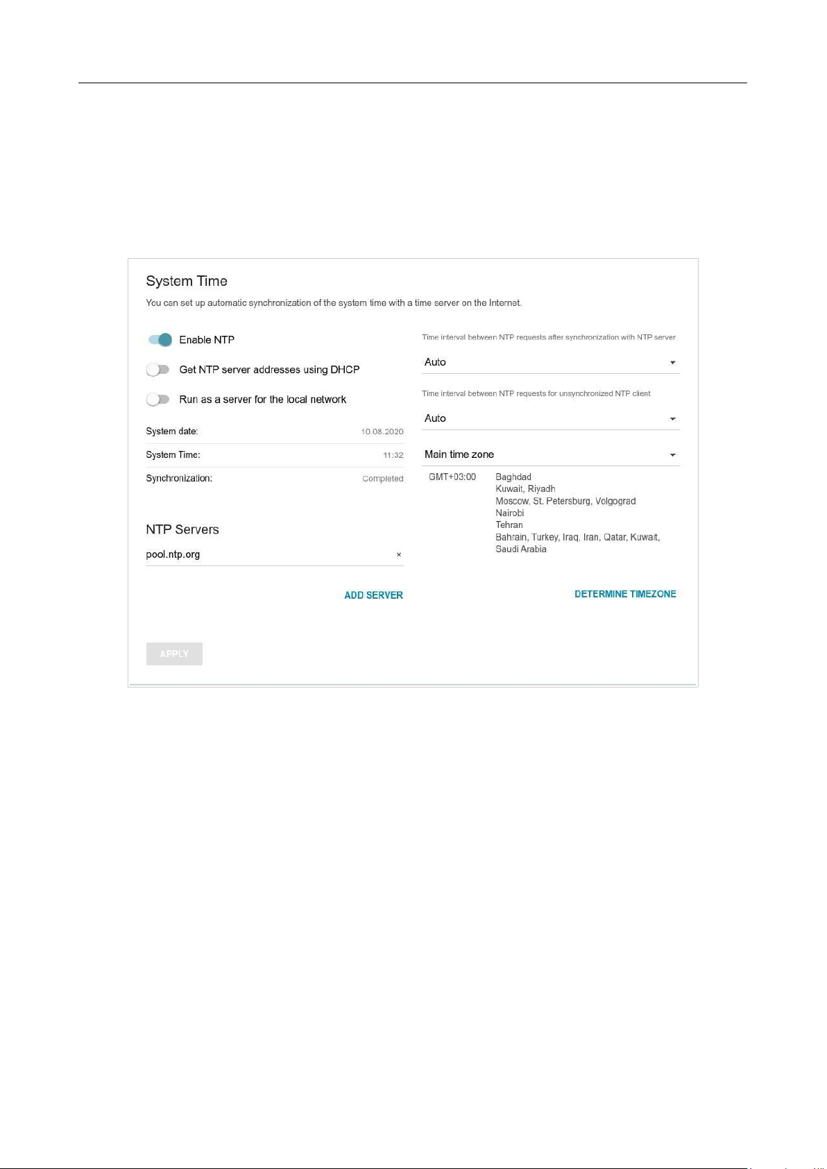
DIR-842V2 AC1200 Wi-Fi Gigabit Router
User Manual
Configuring via Web-based Interface
Page 176 of 200
Management
System Time
On the Management / System Time page, you can manually set the time and date of the router
or configure automatic synchronization of the system time with a time server on the Internet.
Figure 133. The Management / System Time page.
To set the system time manually, follow the next steps:
1. Move the Enable NTP switch to the left.
2. In the Time Settings section, specify needed values. To specify the time set up your PC or
portable device, click the SET LOCAL TIME button.
3. Click the APPLY button. The System date and System time fields will be filled in
automatically.
To enable automatic synchronization with a time server, follow the next steps:
1. Move the Enable NTP switch to the right.
2. Specify the needed NTP server or leave the value specified by default in the NTP Servers
section. If you need to specify several servers, click the ADD SERVER button.
3. Select your time zone from the Main time zone drop-down list. To set the time zone in
accordance with the settings of your operating system or portable device, click the
DETERMINE TIMEZONE button.
4. Click the APPLY button. The System date and System time fields will be filled in

DIR-842V2 AC1200 Wi-Fi Gigabit Router
User Manual
Configuring via Web-based Interface
Page 177 of 200
automatically.

DIR-842V2 AC1200 Wi-Fi Gigabit Router
User Manual
Configuring via Web-based Interface
Page 178 of 200
In some cases NTP servers addresses are provided by your ISP. In this case, you need to move the
Get NTP server addresses using DHCP switch to the right and click the APPLY button.
Contact your ISP to clarify if this setting needs to be enabled. If the Get NTP server addresses
using DHCP switch is moved to the right, the NTP Servers section is not displayed.
To allow connected devices to use the IP address of the router in the local subnet as a time server,
move the Run as a server for the local network switch to the right and click the APPLY button.
!
When the router is powered off or rebooted, the system time is reset to the default value.
If you have set automatic synchronization for the system time, the internal clock of the
device will be configured after connecting to the Internet. If you have set the system time
manually, you need to set the time and date again (see above).
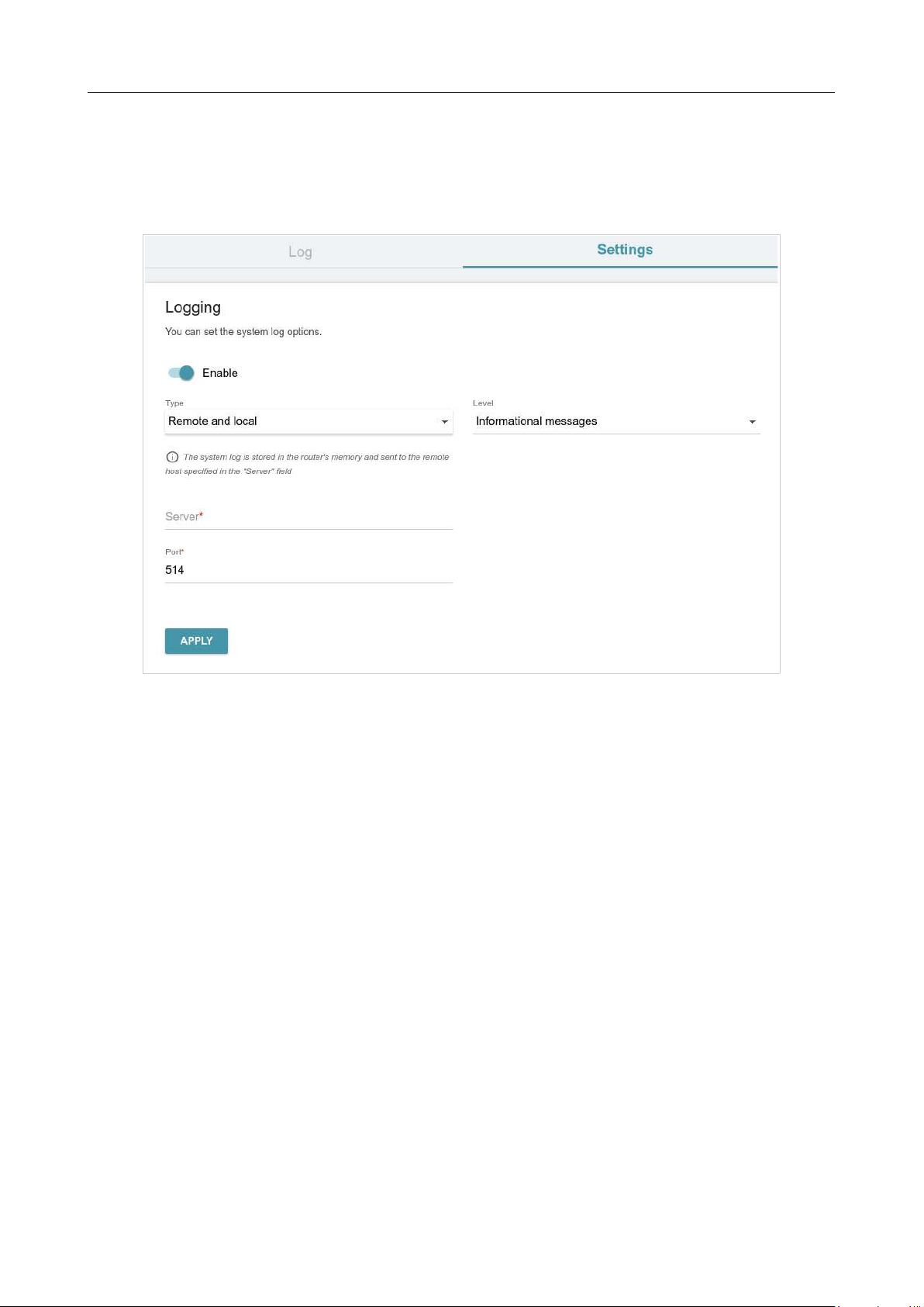
DIR-842V2 AC1200 Wi-Fi Gigabit Router
User Manual
Configuring via Web-based Interface
Page 179 of 200
System Log
On the Management / System Log page, you can set the system log options and configure
sending the system log to a remote host.
Figure 134. The Management / System Log page. The Settings tab.
To enable logging of the system events, go to the Settings tab and move the Enable switch to the
right. Then specify the needed parameters.
DIR-842V2 AC1200 Wi-Fi Gigabit Router
User Manual
Configuring via Web-based Interface
Page 180 of 200
Parameter Description
Logging
Type
Select a type of logging from the drop-down list.
•
Local: the system log is stored in the router's memory. When
this value is selected, the Server and Port fields
are not
displayed.
•
Remote: the system log is sent to the remote host specified in
the Server field.
•
Remote and local
: the system log is stored in the router's
memory and sent to the remote host specified in the Server
field.
Level
Select a type of messages and alerts/notifications to be logged.
Server
The IP or URL address of the host from the local or global network,
to which the system log will be sent.
Port
A port of the host specified in the Server field. By default, the value
514
is specified.
After specifying the needed parameters, click the APPLY button.
To disable logging of the system events, move the Enable switch to the left and click the APPLY
button.

DIR-842V2 AC1200 Wi-Fi Gigabit Router
User Manual
Configuring via Web-based Interface
Page 181 of 200
To view the system log, go to the Log tab.
Figure 135. The Management / System Log page. The Log tab.
To view the latest system events, click the REFRESH button.
To save the system log to your PC, click the EXPORT button. The file will be stored in the
download location of your web browser.
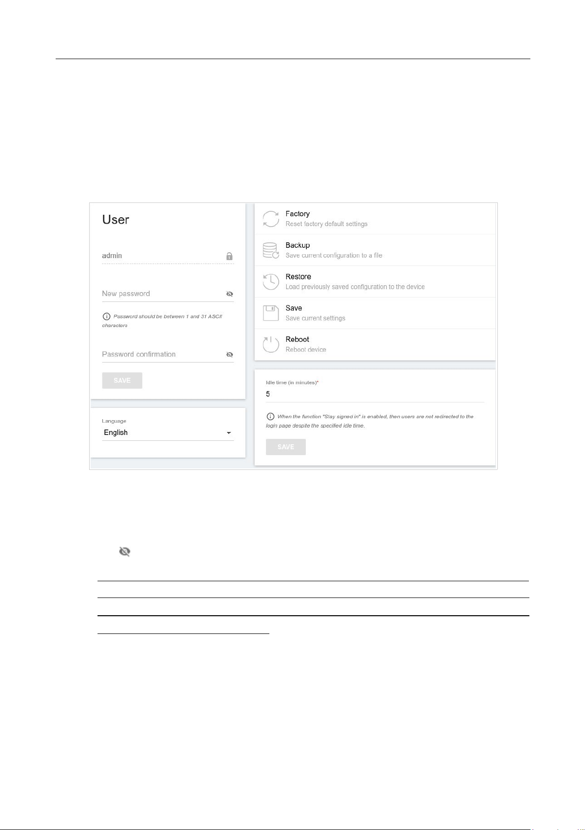
DIR-842V2 AC1200 Wi-Fi Gigabit Router
User Manual
Configuring via Web-based Interface
Page 182 of 200
Administration
On the Management / Administration page, you can change the password for the administrator
account used to access the web-based interface of the router and to access the device settings via
TELNET and SSH, restore the factory defaults, backup the current configuration, restore the router's
configuration from a previously created file, save the changed settings to the non-volatile memory,
reboot the device, or change the web-based interface language.
Figure 136. The Management / Administration page.
In order to change the password for the administrator account, in the User section, enter a new
password in the New password and Password confirmation fields. Use digits, Latin letters
(uppercase and/or lowercase), and other characters available in the US keyboard layout.7
Click the
Show icon ( ) to display the entered values.
Then click the SAVE button.
!
Remember or write down the new password for the administrator account. In case of losing
the new password, you can access the settings of the router only after restoring the factory
default settings via the hardware RESET button. This procedure wipes out all settings that
you have configured for your router.
To change the web-based interface language, select the needed value from the Language drop-
down list.

DIR-842V2 AC1200 Wi-Fi Gigabit Router
User Manual
Configuring via Web-based Interface
Page 183 of 200
7 0-9, A-Z, a-z, space, !"#$%&'()*+,-./:;<=>?@[\]^_`{|}~.

DIR-842V2 AC1200 Wi-Fi Gigabit Router
User Manual
Configuring via Web-based Interface
Page 184 of 200
The following buttons are also available on the page:
Control Description
Factory
Click the button to restore the factory default settings. Also you can
restore the factory defaults via the hardware RESET button (see the
Back Panel section, page 15).
Backup
Click the button to save the configuration (all settings of the router)
to your PC. The configuration backup will be stored in the
download
location of your web browser.
Restore
Click the button and follow the dialog box appeared to select a
previously saved configuration file (all settings of the router)
located
on your PC and upload it.
Save
Click the button to save settings to the non-volatile memory.
The router saves changed settings automatically. If changed settings
have not been saved automatically, a notification is displayed in the
top right part of the page.
Reboot
Click the button to reboot the device. All unsaved changes will be
lost after the device's reboot.
In the Idle time field specify a period of inactivity (in minutes) after which the router completes
the session of the interface. By default, the value 5 is specified. Then click the SAVE button.
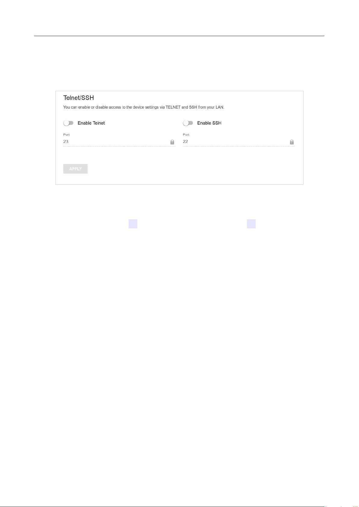
DIR-842V2 AC1200 Wi-Fi Gigabit Router
User Manual
Configuring via Web-based Interface
Page 185 of 200
T
el
n
et
/
SS
H
On the Management / Telnet/SSH page, you can enable or disable access to the device settings
via TELNET and/or SSH from your LAN. By default, access is disabled.
Figure 137. The Management / Telnet/SSH page.
To enable access via TELNET and/or SSH, move the Enable Telnet switch and/or Enable SSH
switch to the right. In the Port field, enter the number of the router's port through which access will
be allowed (by default, the port 23 is specified for Telnet and the port 22 is specified for SSH).
Then click the APPLY button.
To disable access via TELNET and/or SSH again, move the Enable Telnet switch and/or Enable
SSH switch to the left and click the APPLY button.

DIR-842V2 AC1200 Wi-Fi Gigabit Router
User Manual
Configuring via Web-based Interface
Page 186 of 200
Yandex.DNS
This menu is designed to configure the Yandex.DNS service.
Yandex.DNS is a web content filtering service which provides the DNS server, protects a computer
against malicious web sites, and blocks access to adult web sites.
Settings
On the Management / Yandex.DNS / Settings page, you can enable the Yandex.DNS service
and configure its operating mode.
Figure 138. The Management / Yandex.DNS / Settings page.
To get detailed information on the service, click the About Yandex.DNS link.
To enable the Yandex.DNS service, move the Enable switch to the right.
When the service is enabled, the Default Mode section is displayed on the page. Select the needed
choice of the radio button to configure filtering for all devices of the router's network:
• Protection off: when this value is selected, the service provides the DNS server with no
restrictions on access to unsafe web sites;
• Safe: when this value is selected, the service blocks access to malicious and fraudulent web
sites;
• Child: when this value is selected, the service blocks access to malicious and fraudulent
web sites and blocks access to adult content.
Also the selected filtering mode will be applied to all devices newly connected to the router's

DIR-842V2 AC1200 Wi-Fi Gigabit Router
User Manual
Configuring via Web-based Interface
Page 187 of 200
network.

DIR-842V2 AC1200 Wi-Fi Gigabit Router
User Manual
Configuring via Web-based Interface
Page 188 of 200
After specifying all needed parameters, click the APPLY button.
To disable the Yandex.DNS service, move the Enable switch to the left and click the APPLY
button.
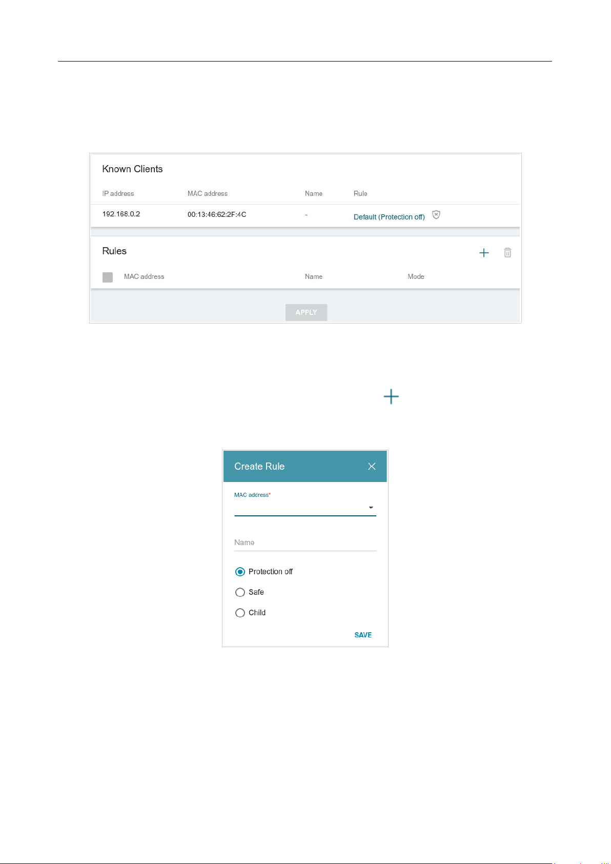
DIR-842V2 AC1200 Wi-Fi Gigabit Router
User Manual
Configuring via Web-based Interface
Page 189 of 200
Devices and Rules
On the Management / Yandex.DNS / Devices and Rules page, you can specify a filtering
mode for each device separately.
Figure 139. The Management / Yandex.DNS / Devices and Rules page.
In the Known Clients section, the devices connected to the local network of the router at the
moment and their relevant filtering mode are displayed.
To create a new filtering rule for a device, click the ADD button ( ) in the Rules section, or left-
click the name of the filtering mode in the line of the device for which a rule should be created in
the Known Clients section.
Figure 140. Adding a new rule for the Yandex.DNS service.

DIR-842V2 AC1200 Wi-Fi Gigabit Router
User Manual
Configuring via Web-based Interface
Page 190 of 200
In the opened window, you can specify the following parameters:
Parameter Description
MAC address
The MAC address of a device from the router's LAN. You can enter
the MAC address of a device connected to the router's LAN at the
moment. To do this, select the relevant device from the drop-down
list (the field will be filled in automatically).
Name
Enter a name for the rule for easier identification. Optional.
Mode
Select an operating mode of the Yandex.DNS service for this rule.
Protection off: when this value is selected, the service provides the
DNS server with no restrictions on access to unsafe web sites.
Safe: when this value is selected, the service blocks access to
malicious and fraudulent web sites.
Child: when this value is selected, the service blocks access to
malicious and fraudulent web sites and blocks access to adult content.
After specifying the needed parameters, click the SAVE button.
To edit a rule for filtering, select a relevant line of the table, in the opened window, change the
needed values and click the SAVE button.
To remove a rule for filtering, select the checkbox located to the left of the relevant rule and click
the DELETE button ( ). Also you can remove a rule in the editing window.
After completing the work with rules, click the APPLY button.
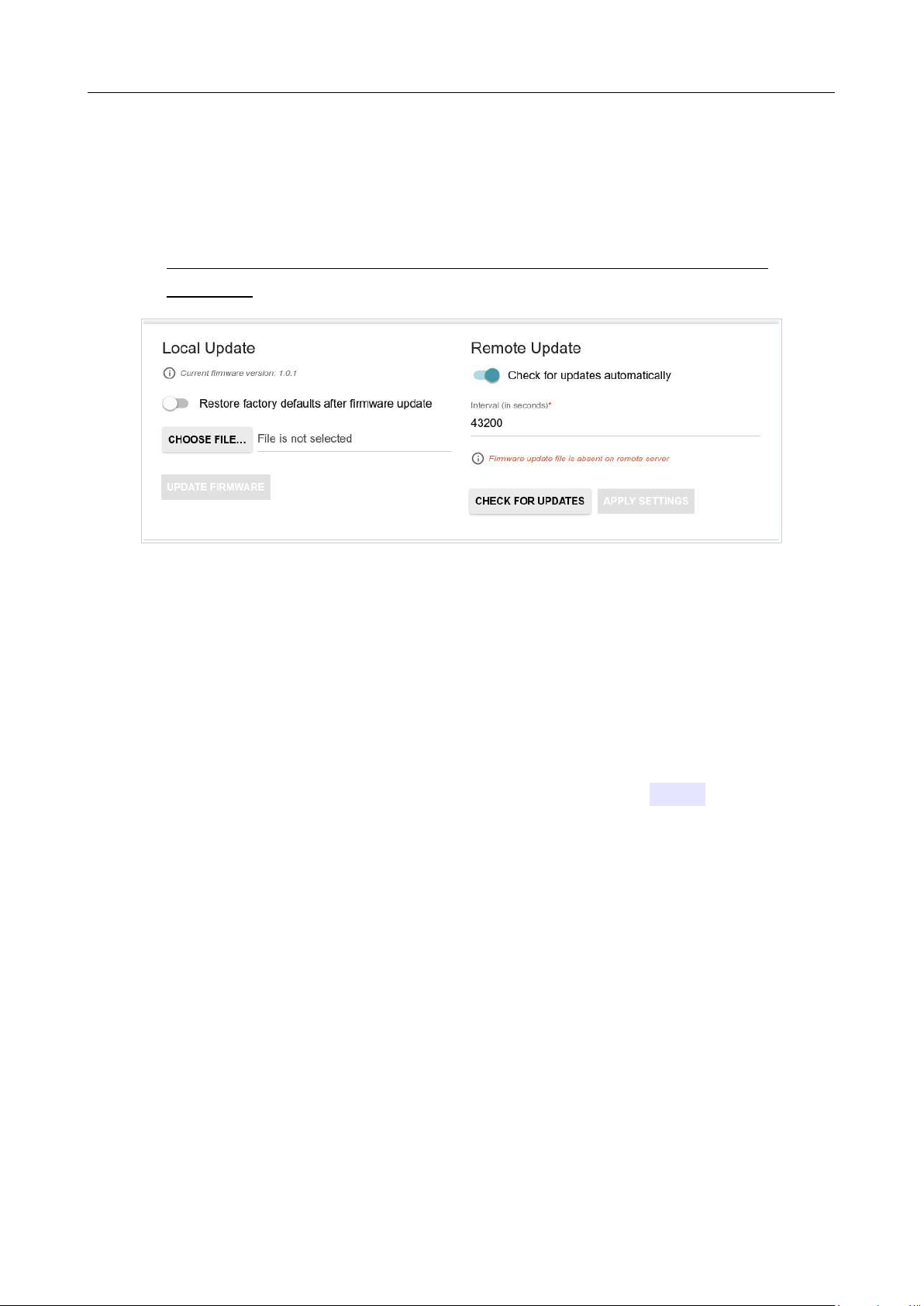
DIR-842V2 AC1200 Wi-Fi Gigabit Router
User Manual
Configuring via Web-based Interface
Page 191 of 200
Firmware Update
On the Management / Firmware Update page, you can update the firmware of the router and
configure the automatic check for updates of the router's firmware.
!
Update the firmware only when the router is connected to your PC via a wired
connection.
Figure 141. The Management / Firmware Update page.
The current version of the router's firmware is displayed in the Current firmware version field.
By default, the automatic check for the router's firmware updates is enabled. If a firmware update is
available, a notification will be displayed in the top right corner of the page.
To disable the automatic check for firmware updates, in the Remote Update section, move the
Check for updates automatically switch to the left and click the APPLY SETTINGS button.
To enable the automatic check for firmware updates, in the Remote Update section, move the
Check for updates automatically switch to the right. In the Interval field, specify the time
period (in seconds) between checks or leave the value specified by default (43200).
You can update the firmware of the router locally (from the hard drive of your PC) or remotely
(from the update server).

DIR-842V2 AC1200 Wi-Fi Gigabit Router
User Manual
Configuring via Web-based Interface
Page 192 of 200
Local Update
!
Attention! Do not turn off the router before the firmware update is completed. This may
cause the device breakdown.
To update the firmware of the router locally, follow the next steps:
1. Download a new version of the firmware from
www.dlink.ru.
2. Click the CHOOSE FILE button in the Local Update section on the Management /
Firmware Update page to locate the new firmware file.
3. If you want to restore the factory default settings immediately after updating the firmware,
move the Restore factory defaults after firmware update switch to the right.
4. Click the UPDATE FIRMWARE button.
5. Wait until the router is rebooted (about one and a half or two minutes).
6. Log into the web-based interface using the login (admin) and the current password.
If after updating the firmware the router doesn't work correctly, please restore the factory default
settings. To do this, click the Factory button on the Management / Administration page. Wait
until the router is rebooted.

DIR-842V2 AC1200 Wi-Fi Gigabit Router
User Manual
Configuring via Web-based Interface
Page 193 of 200
Remote Update
!
Attention! Do not turn off the router before the firmware update is completed. This may
cause the device breakdown.
To update the firmware of the router remotely, follow the next steps:
1. On the Management / Firmware Update page, in the Remote Update section, click
the CHECK FOR UPDATES button to check if a newer firmware version exists.
2. Click the UPDATE FIRMWARE button (the button is displayed if a newer version of the
firmware is available).
3. Wait until the router is rebooted (about one and a half or two minutes).
4. Log into the web-based interface using the login (admin) and the current password.
If after updating the firmware the router doesn't work correctly, please restore the factory default
settings. To do this, click the Factory button on the Management / Administration page. Wait
until the router is rebooted.
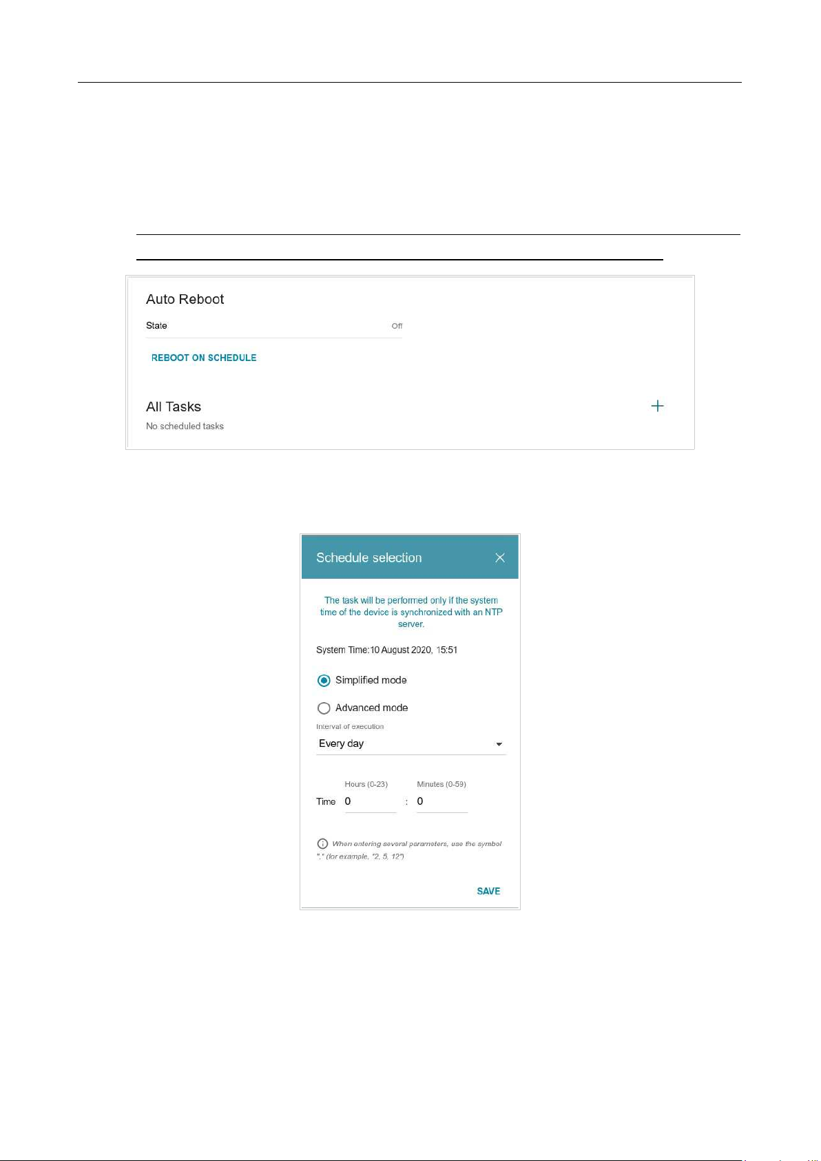
DIR-842V2 AC1200 Wi-Fi Gigabit Router
User Manual
Configuring via Web-based Interface
Page 194 of 200
Schedule
On the Management / Schedule page, you can enable/disable Wi-Fi connection and configure
automatic reboot of the device on a schedule, and set a schedule for different filter rules.
!
Before creating a schedule you need to configure automatic synchronization of the system
time with a time server on the Internet (see the System Time section, page 166).
Figure 142. The Management / Schedule page.
To configure automatic reboot of the device on a schedule, click the REBOOT ON SCHEDULE
button in the Auto Reboot section.
Figure 143. The window for configuring automatic reboot on a schedule.

DIR-842V2 AC1200 Wi-Fi Gigabit Router
User Manual
Configuring via Web-based Interface
Page 195 of 200
In the opened window, in the System Time field, the system time of the device is displayed. You
can select the Simplified mode choice of the radio button and specify the following parameters:
Parameter Description
Simplified mode
Interval of execution
Specify the time period for the device's reboot.
Every day: When this value is selected, the Time field is displayed
in the section.
Every week: When this value is selected, the names of days of the
week and the Time field are displayed in the section.
Every month: When this value is selected, the Day of month and
Time fields are displayed in the section.
Time
Specify the time for the device's reboot.
Days of week
Select a day or days of the week when the device will be
automatically
rebooted. To do this, select the checkbox located to the left of the
relevant value.
Day of month
Specify a day of the month. You can specify one value or several
values separated by a comma.
In the advanced mode, you can specify more parameters for the schedule using a cron expression.
To do this, select the Advanced mode choice of the radio button and specify the needed values in
the fields displayed. You can specify one value or several values separated by a comma. You can
use the character * (asterisk) to specify the entire range of possible values. Upon that the Schedule
field will be filled in automatically.
Click the SAVE button.
To edit the automatic reboot schedule, click the EDIT button in the Auto Reboot section. In the
opened window, change the needed parameters and click the SAVE button.
To disable automatic reboot of the device on a schedule, click the EDIT button in the Auto
Reboot section. In the opened window, click the DISABLE button.
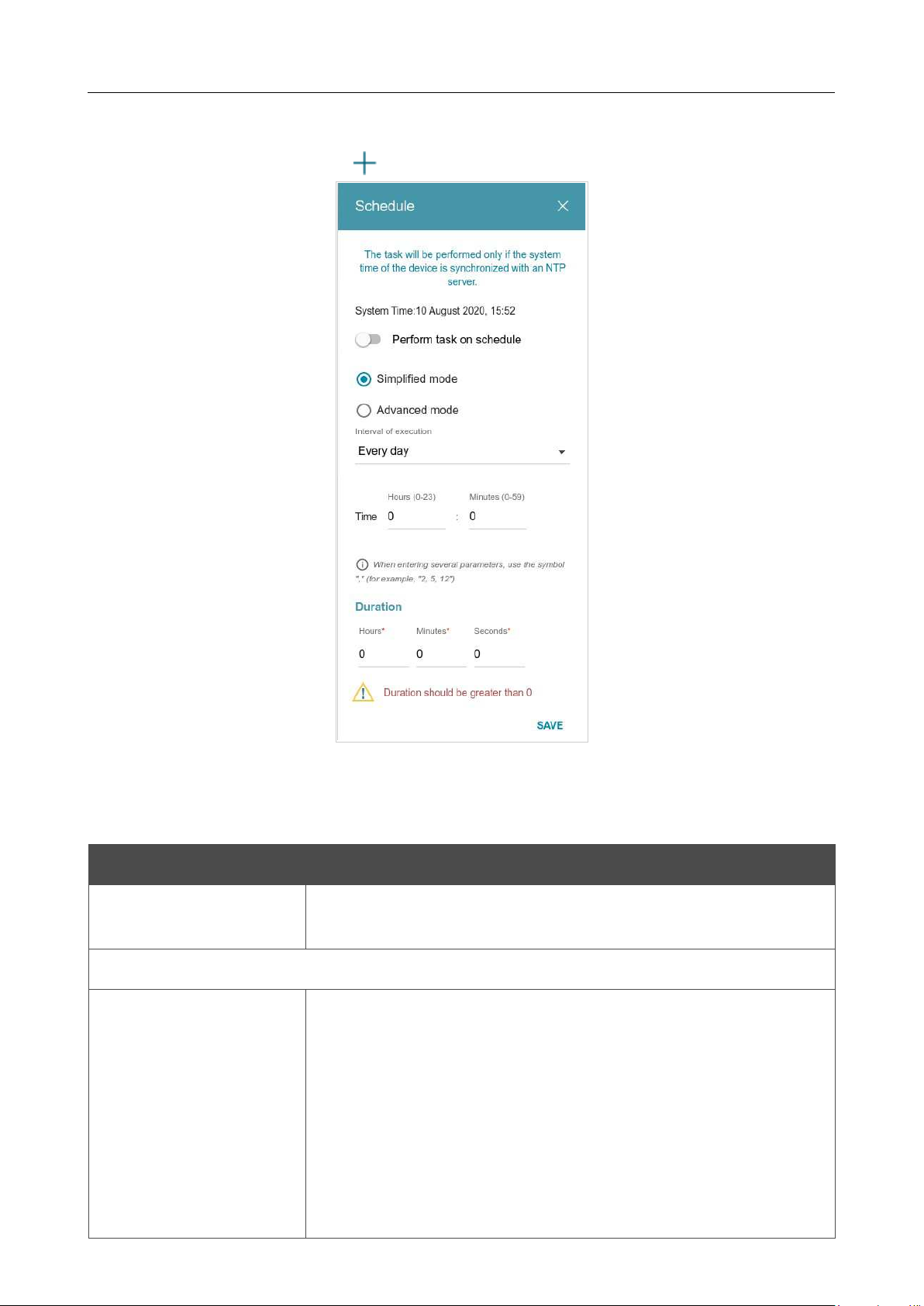
DIR-842V2 AC1200 Wi-Fi Gigabit Router
User Manual
Configuring via Web-based Interface
Page 196 of 200
To set a schedule for a task which will be applied to a filter rule or will enable/disable Wi-Fi
connection, click the ADD button ( ) in the All Tasks section.
Figure 144. The window for adding a schedule for a task.
In the opened window, in the System Time field, the system time of the device is displayed. You
can select the Simplified mode choice of the radio button and specify the following parameters:
Parameter Description
Perform task on
schedule
Move the switch to the right to enable the schedule.
Move the switch to the left to disable the schedule.
Simplified mode
Interval of execution
Specify the time period for performing a task.
Every minute.
Every hour: When this value is selected, the Time field is
displayed in the section.
Every day: When this value is selected, the Time field is displayed
in the section.
Every week: When this value is selected, the names of days of the
week and the Time field are displayed in the section.

DIR-842V2 AC1200 Wi-Fi Gigabit Router
User Manual
Configuring via Web-based Interface
Page 197 of 200
Parameter Description
Every month: When this value is selected, the Day of month and
Time fields are displayed in the section.
Duration
Specify the interval during which the task will be performing.
Time
Specify the time when the task should start running.
Days of week
Select a day or days of the week when the task will be performing.
To
do this, select the checkbox located to the left of the relevant value.
Day of month
Specify a day of the month. You can specify one value or several
values separated by a comma.
In the advanced mode, you can specify more parameters for the schedule using a cron expression.
To do this, select the Advanced mode choice of the radio button and specify the needed values in
the fields displayed. You can specify one value or several values separated by a comma. You can
use the character * (asterisk) to specify the entire range of possible values. Upon that the Schedule
field will be filled in automatically.
Click the SAVE button.
To edit a schedule, in the All Tasks section, select the relevant line in the table. In the opened
window, change the needed parameters and click the SAVE button.
To remove a schedule, in the All Tasks section, select the checkbox located to the left of the
relevant line in the table and click the DELETE button ( ).
To assign a created schedule to a task which will be applied to a filter rule or will enable/disable
Wi-Fi connection, go to the relevant page of the web-based interface of the device.
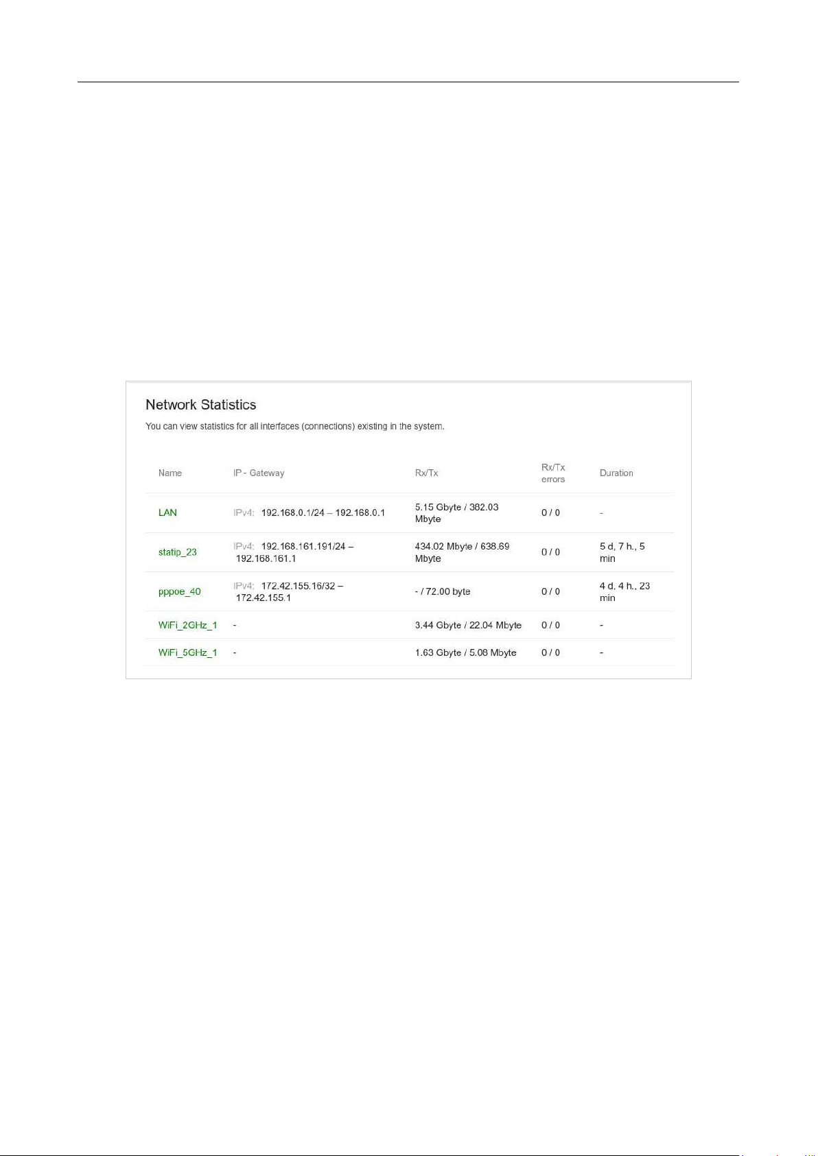
DIR-842V2 AC1200 Wi-Fi Gigabit Router
User Manual
Configuring via Web-based Interface
Page 198 of 200
Statistics
The pages of this section display data on the current state of the router.
Network Statistics
On the Management / Statistics / Network Statistics page, you can view statistics for all
connections existing in the system (WAN connections, LAN, WLAN). For each connection the
following data are displayed: name and state (when the connection is on, its name is highlighted in
green, when the connection is off, its name is highlighted in red), IP address and subnet mask, and
volume of data received and transmitted (with increase of the volume the units of measurement are
changed automatically: byte, Kbyte, Mbyte, Gbyte).
Figure 145. The Management / Statistics / Network Statistics page.
To view detailed data on a connection, click the line corresponding to this connection.
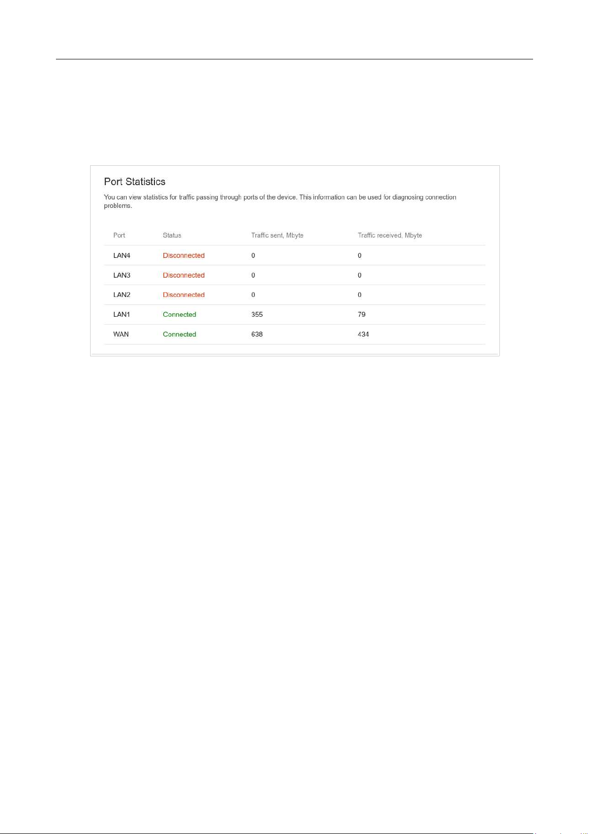
DIR-842V2 AC1200 Wi-Fi Gigabit Router
User Manual
Configuring via Web-based Interface
Page 199 of 200
Port Statistics
On the Management / Statistics / Port statistics page, you can view statistics for traffic passing
through ports of the router. The information shown on the page can be used for diagnosing connection
problems.
Figure 146. The Management / Statistics / Port Statistics page.
To view the full list of counters for a port, click the line corresponding to this port.
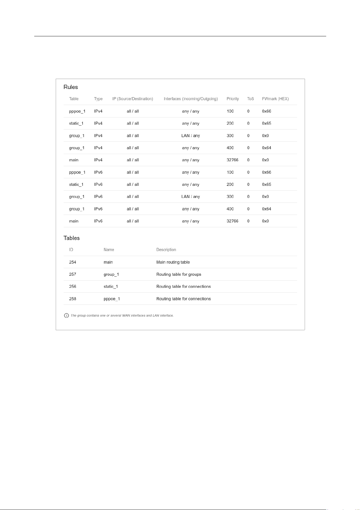
DIR-842V2 AC1200 Wi-Fi Gigabit Router
User Manual
Configuring via Web-based Interface
Page 200 of 200
Routing
The Management / Statistics / Routing page displays the routing rules and routing tables.
Figure 147. The Management / Statistics / Routing page.
The Rules section displays routing rules, their corresponding routing tables, incoming and
outgoing interfaces, priority levels, and other data.
The Tables section displays the list of routing tables stored in the device's memory. To view
detailed information on routes, left-click the relevant line in the table.
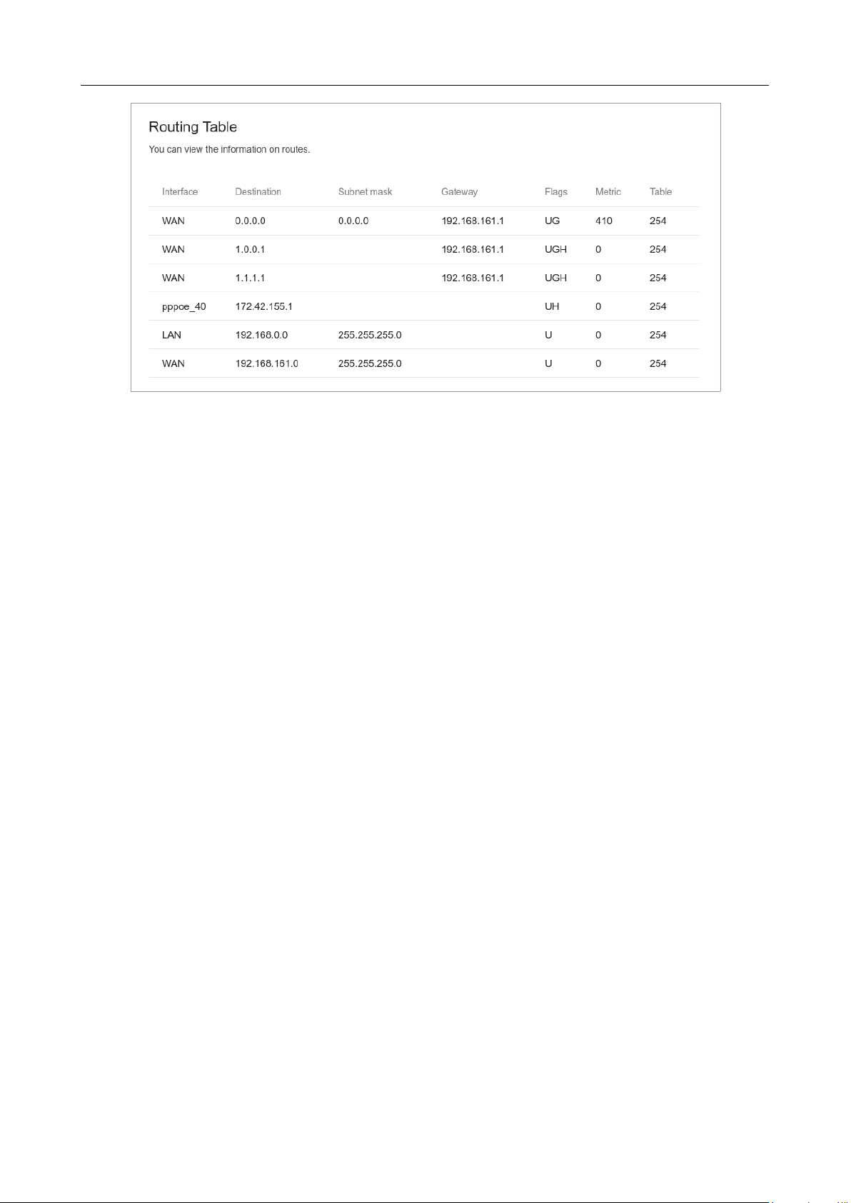
DIR-842V2 AC1200 Wi-Fi Gigabit Router
User Manual
Configuring via Web-based Interface
Page 201 of 200
Figure 148. The routing table page.
The opened page displays the information on routes in the selected routing table. The table contains
destination IP addresses, gateways, subnet masks, and other data.

DIR-842V2 AC1200 Wi-Fi Gigabit Router
User Manual
Configuring via Web-based Interface
Page 202 of 200
DHCP
The Management / Statistics / DHCP page displays the information on computers that have been
identified by hostnames and MAC addresses and have got IP addresses from the DHCP server of the
device.
Figure 149. The Management / Statistics / DHCP page.
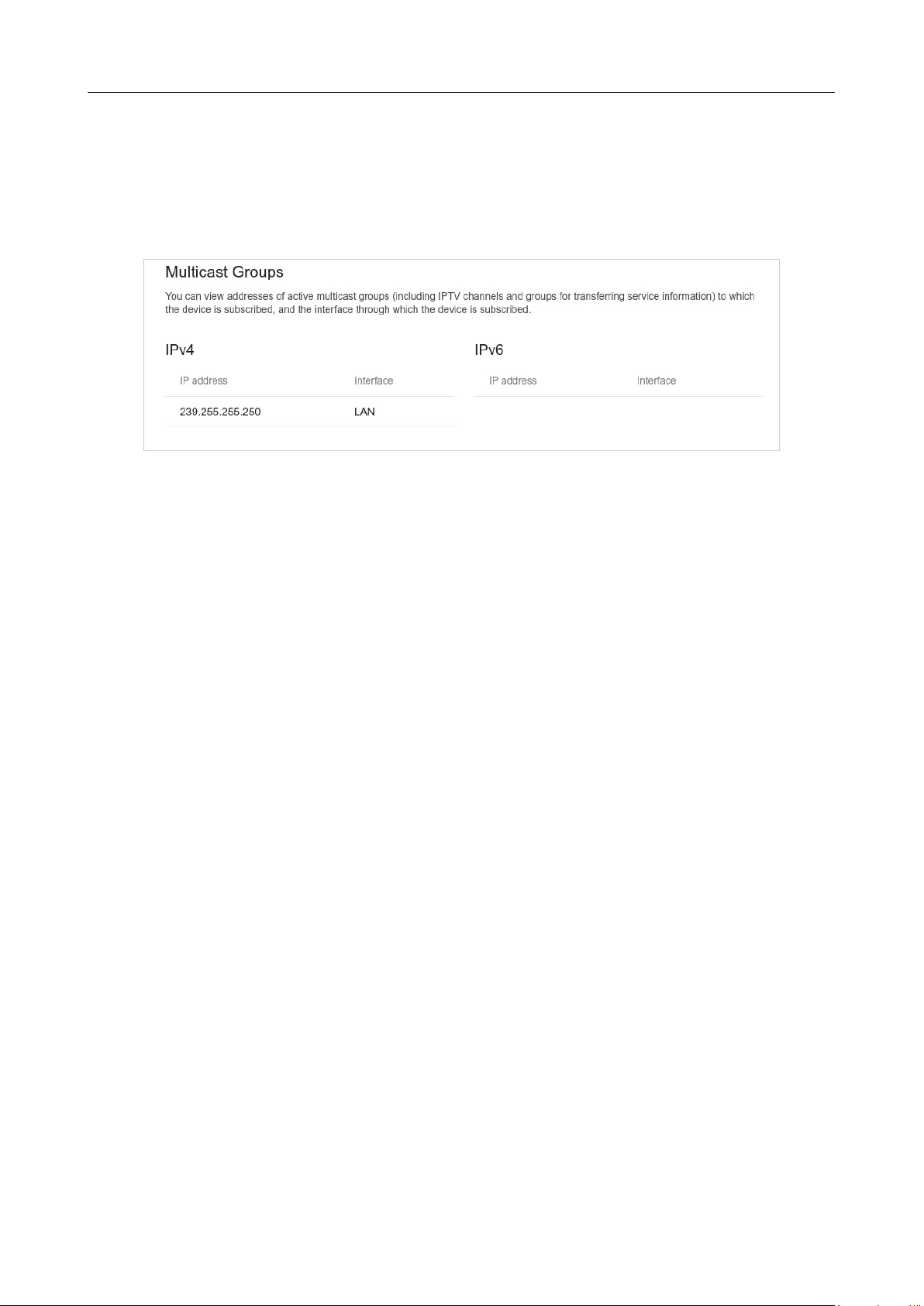
DIR-842V2 AC1200 Wi-Fi Gigabit Router
User Manual
Configuring via Web-based Interface
Page 203 of 200
Multicast Groups
The Management / Statistics / Multicast Groups page displays addresses of active multicast
groups (including IPTV channels and groups for transferring service information) to which the device
is subscribed, and the interface through which the device is subscribed.
Figure 150. The Management / Statistics / Multicast Groups page.
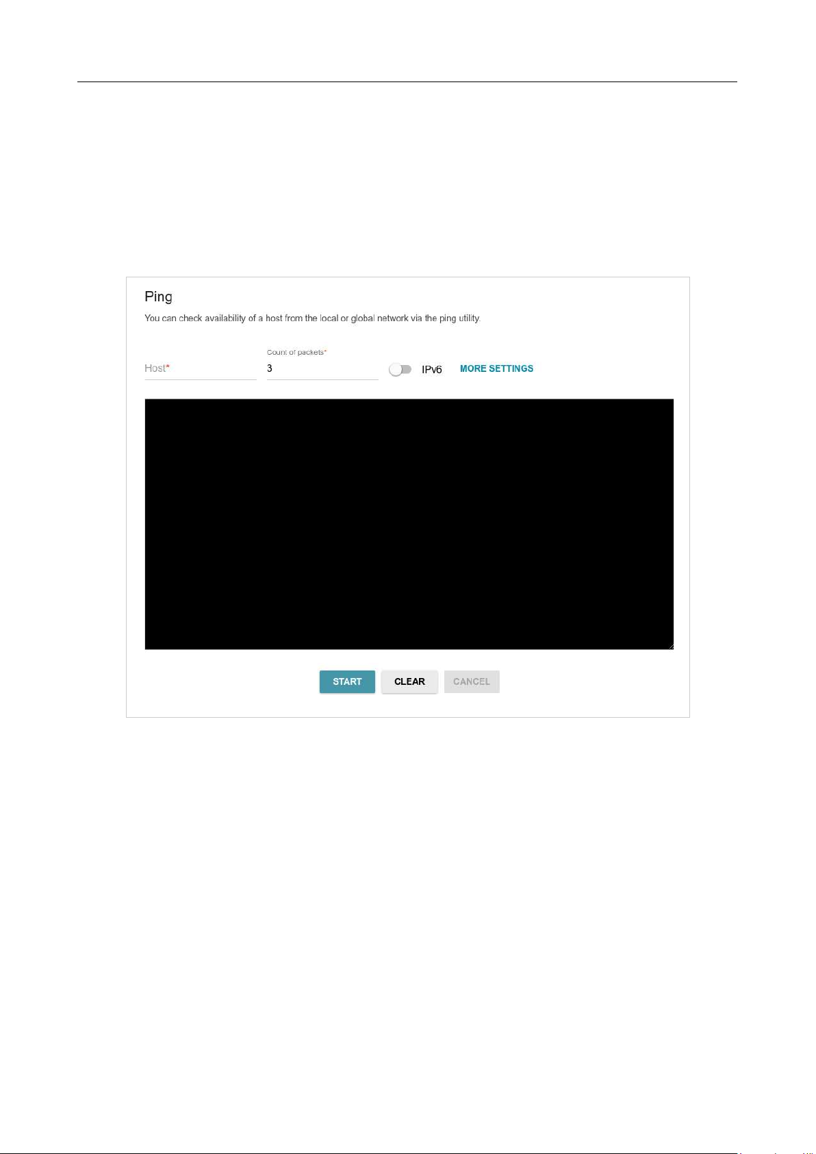
DIR-842V2 AC1200 Wi-Fi Gigabit Router
User Manual
Configuring via Web-based Interface
Page 204 of 200
Diagnostics
Ping
On the Management / Diagnostics / Ping page, you can check availability of a host from the
local or global network via the Ping utility.
The Ping utility sends echo requests to a specified host and receives echo replies.
Figure 151. The Management / Diagnostics / Ping page.
To check availability of a host, enter the IP address or name of this host in the Host field and specify
a number of requests that will be sent in order to check its availability in the Count of packets
field. If availability check should be performed with IPv6, move the IPv6 switch to the right.
To specify additional settings, click the MORE SETTINGS button.

DIR-842V2 AC1200 Wi-Fi Gigabit Router
User Manual
Configuring via Web-based Interface
Page 205 of 200
Figure 152. The Management / Diagnostics / Ping page. The additional settings window.
In the opened window, in the Packet size field, specify the volume of data sent in a request. In the
Time to wait for a response field, specify the response waiting period in seconds. To restore the
default field values, click the DEFAULT SETTINGS button.
After specifying the additional parameters, click the OK button.
To run the check, click the START button. After a while, the results will be displayed on the page.
If you need to interrupt the check, click the CANCEL button (the button is available from the
moment the check starts).
To remove the check result from the page, click the CLEAR button.
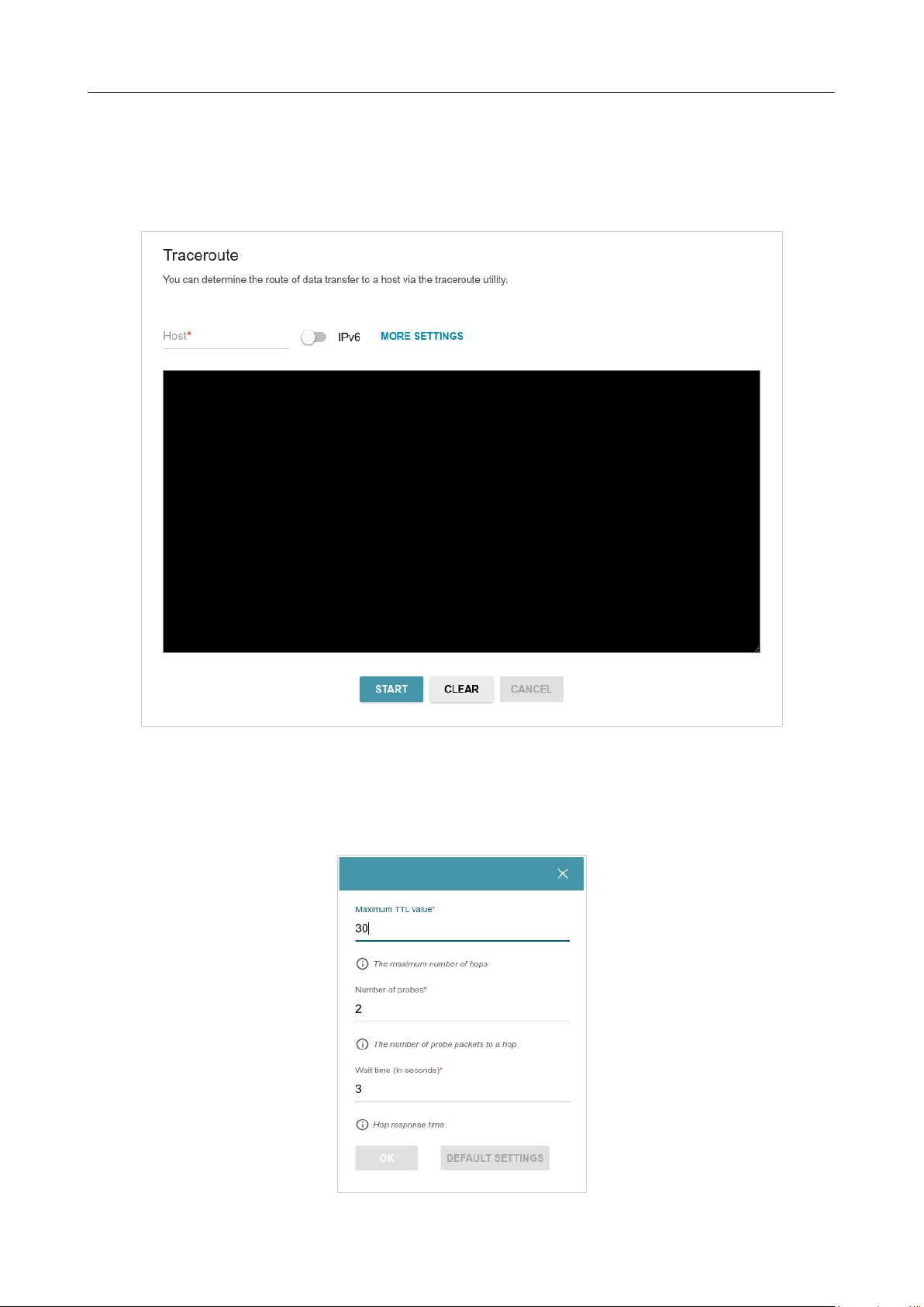
DIR-842V2 AC1200 Wi-Fi Gigabit Router
User Manual
Configuring via Web-based Interface
Page 206 of 200
Traceroute
On the Management / Diagnostics / Traceroute page, you can determine the route of data
transfer to a host via the traceroute utility.
Figure 153. The Management / Diagnostics / Traceroute page.
To determine the route, enter the name or IP address of a host in the Host field. If the route should
be determined using IPv6, move the IPv6 switch to the right.
To specify additional settings, click the MORE SETTINGS button.
Figure 154. The Management / Diagnostics / Traceroute page. The additional settings window.

DIR-842V2 AC1200 Wi-Fi Gigabit Router
User Manual
Configuring via Web-based Interface
Page 207 of 200
In the opened window, you can specify the following parameters:
Parameter Description
Maximum TTL value
Specify the TTL (Time to live) parameter value. The default value is
30
.
Number of probes
The number of attempts to hit an intermediate host.
Wait time
A period of waiting for an intermediate host response.
To restore the default field values, click the DEFAULT SETTINGS button.
After specifying the additional parameters, click the OK button.
To run the check, click the START button. After a while, the results will be displayed on the page.
The additional settings window.
If you need to interrupt the check, click the CANCEL button (the button is available from the
moment the check starts).
To remove the check result from the page, click the CLEAR button.

DIR-842V2 AC1200 Wi-Fi Gigabit Router
User Manual
Operation Guidelines
Page 208 of 200
CHAPTER 5. OPERATION GUIDELINES
Safety Rules and Conditions
Please carefully read this section before installation and connection of the device. Make sure that
the power adapter and cables are not damaged. The device should be used only as intended in
accordance with the documents.
The device is intended for use in dry, clean, dust-free, and well ventilated areas with normal humidity
away from strong heat sources. Do not use the device outdoors or in the areas with high humidity. Do
not place foreign objects on the device. Do not obstruct the ventilation openings of the device. The
environmental temperature near the device and the temperature inside the device's cover should
be within the range from 0 °С to +40 °С.
Only use the power adapter supplied with the device. Do not plug in the adapter, if its case or cable
are damaged. Plug the adapter only into working electrical outlets with parameters indicated on the
adapter.
Do not open the cover of the device! Unplug the device before dusting and cleaning. Use a damp
cloth to clean the device. Do not use liquid/aerosol cleaners or magnetic/static cleaning devices.
Prevent moisture getting into the device or the power adapter.
The service life of the device is 2 years.

DIR-842V2 AC1200 Wi-Fi Gigabit Router
User Manual
Operation Guidelines
Page 209 of 200
Wireless Installation Considerations
The DIR-842V2 device lets you access your network using a wireless connection from virtually
anywhere within the operating range of your wireless network. Keep in mind, however, that the
number, thickness and location of walls, ceilings, or other objects that the wireless signals must pass
through, may limit the range. Typical ranges vary depending on the types of materials and background
RF noise in your home or office. To maximize your wireless range, follow the guidelines below.
1. Keep the number of walls and ceilings between the DIR-842V2 device and other network
devices to a minimum – each wall or ceiling can reduce your wireless network range by 3- 90
feet (1-30 meters).
2. Be aware of the direct line between network devices. Place your devices so that the signal
travels straight through a wall or ceiling (instead of at an angle) for better reception.
3. Building materials make a difference. A solid metal door or aluminum studs may have a
negative effect on your wireless range. Try to position your router, access points, and
computers so that the signal passes through drywalls or open doorways. Materials and objects
such as glass, steel, metal, walls with insulation, water (fish tanks), mirrors, file cabinets, brick,
and concrete will degrade your wireless signal.
4. Keep your router away (at least 3-6 feet or 1-2 meters) from electrical devices or appliances
that generate RF noise.
5. If you are using 2.4 GHz cordless phones or X-10 equipment (wireless devices such as ceiling
fans, lights, and home security systems), your wireless connection may degrade dramatically
or drop completely. Make sure your 2.4 GHz phone base is as far away from your wireless
devices as possible. Note, that the base transmits a signal even if the phone in not in use.

DIR-842V2 AC1200 Wi-Fi Gigabit Router
User Manual
Abbreviations and Acronyms
Page 210 of 200
CHAPTER 6. ABBREVIATIONS AND ACRONYMS
3G
Third Generation
AC
Access Category
AES
Advanced Encryption Standard
AP
Access Point
ARP
Address Resolution Protocol
BPSK
Binary Phase-shift Keying
BSSID
Basic Service Set Identifier
CCK
Complementary Code Keying
DBSK
Differential Binary Phase-shift Keying
DDNS
Dynamic Domain Name System
DDoS
Distributed Denial of Service
DES
Data Encryption Standard
DHCP
Dynamic Host Configuration Protocol
DMZ
DeMilitarized Zone
DNS
Domain Name System
DPD
Dead Peer Detection
DQPSK
Differential Quadrature Phase-shift Keying
DSL
Digital Subscriber Line
DSSS
Direct-sequence Spread Spectrum
DTIM
Delivery Traffic Indication Message
GMT
Greenwich Mean Time
GSM
Global System for Mobile Communications
HTTP
Hypertext Transfer Protocol
HTTPS
Hypertext Transfer Protocol Secure
ICMP
Internet Control Message Protocol
ID
Identifier
IGD
Internet Gateway Device

DIR-842V2 AC1200 Wi-Fi Gigabit Router
User Manual
Abbreviations and Acronyms
Page 211 of 200
IGMP
Internet Group Management Protocol
IKE
Internet Key Exchange
IMEI
International Mobile Equipment Identity
IMSI
International Mobile Subscriber Identity
IP
Internet Protocol
IPTV
Internet Protocol Television
IPsec
Internet Protocol Security
ISP
Internet Service Provider
L2TP
Layer 2 Tunneling Protocol
LAN
Local Area Network
LCP
Link Control Protocol
LED
Light-emitting diode
LTE
Long Term Evolution
MAC
Media Access Control
MBSSID
Multiple Basic Service Set Identifier
MIB
Management Information Base
MIMO
Multiple Input Multiple Output
MPPE
Microsoft Point-to-Point Encryption
MS-CHAP
Microsoft Challenge Handshake Authentication Protocol
MTU
Maximum Transmission Unit
NAT
Network Address Translation
NIC
Network Interface Controller
NTP
Network Time Protocol
OFDM
Orthogonal Frequency Division Multiplexing
PBC
Push Button Configuration
PFS
Perfect Forward Secrecy
PIN
Personal Identification Number
PoE
Power over Ethernet

DIR-842V2 AC1200 Wi-Fi Gigabit Router
User Manual
Abbreviations and Acronyms
Page 212 of 200
PPP
Point-to-Point Protocol
pppd
Point-to-Point Protocol Daemon
PPPoE
Point-to-point protocol over Ethernet
PPTP
Point-to-point tunneling protocol
PSK
Pre-shared key
PUK
PIN Unlock Key
QAM
Quadrature Amplitude Modulation
QoS
Quality of Service
QPSK
Quadrature Phase-shift Keying
RADIUS
Remote Authentication in Dial-In User Service
RIP
Routing Information Protocol
RIPng
Next Generation Routing Information Protocol
RTS
Request To Send
RTSP
Real Time Streaming Protocol
SA
Security Association
SAE
Simultaneous Authentication of Equals
SIM
Subscriber Identification Module
SIP
Session Initiation Protocol
SMB
Server Message Block
SNMP
Simple Network Management Protocol
SSH
Secure Shell
SSID
Service Set Identifier
STBC
Space-time block coding
TCP
Transmission Control Protocol
TKIP
Temporal Key Integrity Protocol
UDP
User Datagram Protocol
UPnP
Universal Plug and Play
URL
Uniform Resource Locator

DIR-842V2 AC1200 Wi-Fi Gigabit Router
User Manual
Abbreviations and Acronyms
Page 213 of 200
USB
Universal Serial Bus
VLAN
Virtual Local Area Network
VPN
Virtual Private Network
WAN
Wide Area Network
WEP
Wired Equivalent Privacy
Wi-Fi
Wireless Fidelity
WISP
Wireless Internet Service Provider
WLAN
Wireless Local Area Network
WMM
Wi-Fi Multimedia
WPA
Wi-Fi Protected Access
WPS
Wi-Fi Protected Setup