Loading ...
— Components for B-5000 Sparking
Before commencing installation,
ensure you have identified the following.
1. Boiling water module
2. Chilled water module
3. Sparkling control box
4. CO2 regulator and cylinder
5. Dispenser upper with tubing
6. Dispenser base & mount
7. Barb locking bush
8. 4mm chrome screw & allen key
9. Large washer
10. Tube spring clamps x 3
11. 90° John Guest elbow
12. White 1/4” tube x 3
13. 600mm flexible braided hose
14. Filter cartridge (installed)
15. User guide
16. Warranty registration card
17. Warning label
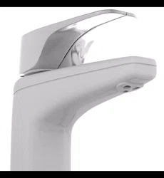
—Determine Unit Location
Plan the installation. Dispenser tube lengths,
position of power and water outlets, required
air space around the underbench modules and
access for service must be considered before
cutting tube lengths refer to Diagrams 1,3a
and 3b for clearances around units. Refer to
Diagrams 4a and 4b for suggested layouts.
—Water Supply
The B-5000 Sparking must only be connected
to a cold water supply. A ½” BSP stop tap
(not supplied) is to be installed in an easily
accessible position within 600mm from
the boiling water module water supply inlet.
Dynamic water supply pressure:
Min. 250 kPa, max. 1000 kPa.
Minimum water supply: 6 l/m at 250 kPa
Supply temp: min. 5°C, max. 30°C.
Do not install with water that is
microbiologically unsafe or with water of
unknown quality without adequate disinfection
before or after the system. Systems certified
for cyst reduction may be used on disinfected
water that may contain filterable cysts.
—Power Requirements
Two 3 pin 10 amp GPOs are required. A
dedicated circuit should be provided and must
be fitted with an earth leakage protection
device (RCD). An externally fitted RCD device is
acceptable.
Both B-5000 Sparkling modules are supplied
with a 1 metre flex cord and plug.
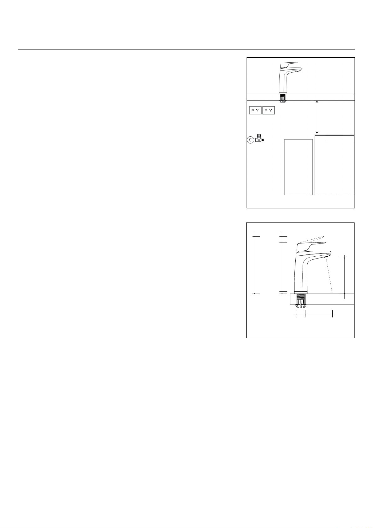
Installation requirements.
XL
215mm
185mm
20mm
Bench
thickness
1mm-54mm
Diagram 2
10mm
145mm
35mm 100mm
Diagram 1
Power
Outlet x 2
800mm
Tube length
supplied
Stop tap
(installed by plumber)
Max 600mm from unit
Cupboard dimensions:
555mm minimum width
460mm minimum depth
60mm
Minimum
clearance
Loading ...
Loading ...
Loading ...