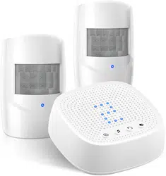
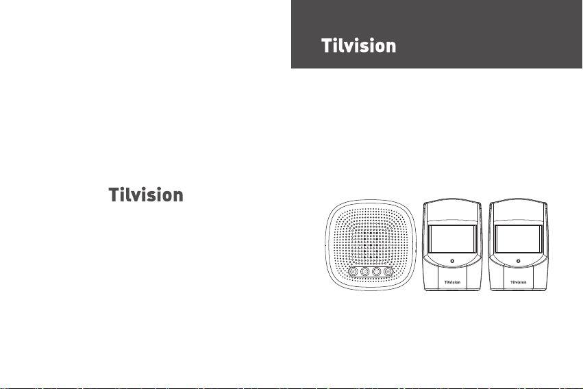
Wireless Driveway Alarm
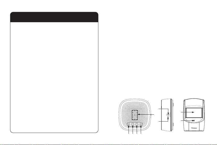
Table of Contents
Thank you for purchasing Tilvision Wireless Driveway Alert
Alarm kit. Please read this instrucon manual before use to
ensure safe operaon.
This new Wireless Driveway Alarm has a 1000 (300m) range
and is great for mulple applicaons including:
Alerng you when visitors enter your driveway.
Deterring trespassers or thieves from entering your home or
property.
Alerng you to wildlife on your property, and so much more!
If you have any quesons about your product, contact our
customer service for assistance.
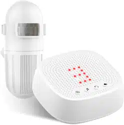
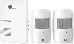
1. Package Includes:
●
1 x Receiver
●
2 x PIR Sensors
●
6 x Screws and Plugs
●
1 x Screwdriver
●
1 x Instrucon Manual
2. Parts Names:
- 01 -
(9)
(8)
(5)
(6)
(7)
(1)(2) (3) (4)
1. Package Includes........................................................
01
2. Parts Names...............................................................
01
3. Geng Started...........................................................02
3.1 Power for Receiver......................................................................02
3.2 Power for PIR sensor...................................................................03
3.3 Paring the PIR sensors with the Receiver....................................04
3.4 Choose an Alarm Melody for the Sensors..................................
07
3.5 Installing the PIR sensor..............................................................08
3.6 Installing the Receiver.................................................................11
3.7 Selecng the Alert Mode for the Receiver..................................12
3.8 Manufacture Default Sengs.....................................................13
3.9 Change the Volume of the Melody.............................................
14
4. Specificaon...............................................................15
5. Troubleshoong.........................................................
15
6. Quesons?.................................................................
18
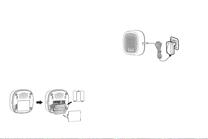
If powering by a power adapter, insert the adapter’s connector
into the DC power jack on the side of the receiver, then plug
the adapter into a power outlet. Please note that an adapter
is not included and needs to be purchased separately.
- 02 - - 03 -
Note:
The specificaons for the power adapter should be -
Input: 110-120V for US, 220-240V for EU. Output: DC 5V/6V
(Refer to the rang label on the adapter). Please note that
our receiver does not use rechargeable lithium baeries, all
baeries MUST BE removed from the receiver when being
powered by a power adapter.
3.2 Power for PIR sensor
The PIR sensor runs on 3 x AAA baeries and works wirelessly
at a maximum distance from the receiver of 1000 (300m).
To insert baeries into the PIR sensor:
●
Remove the screw on the baery compartment cover at the
black of the sensor. This screw is very small, so be careful not
to lose it.
1. Pairing buon 2. Melody / Next buon
3. Alert Mode Buon
4. Volume buon
5. Zone LED indicator
6. DC power jack
7. Receiver power indicator
8. PIR Sensor
9. PIR sensor working indicator
3. Geng Started:
3.1 Power for Receiver
The receiver can be powered by 3 x AA baeries or by a
power adapter (output: DC 5.0V).
(BATTERIES AND ADAPTER NOT INCLUDED)
If powering by baeries, please insert the baeries using
the following procedure:
●
Remove the baery compartment cover at the back of
the receiver.
●
Insert 3 x AA type baeries into the baery compartment,
using the correct polarity to eliminate the danger of fire.
●
Snap the baery compartment back into place.
3xAA 1.5V
Alkaline Baery
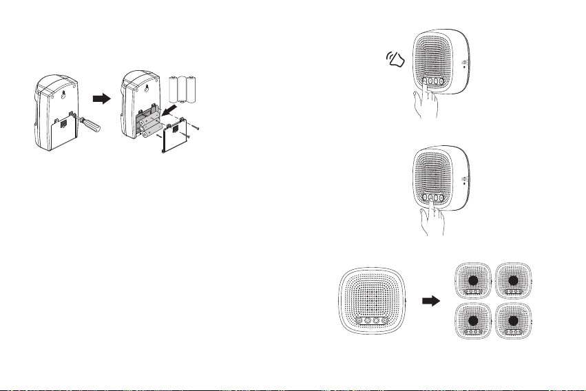
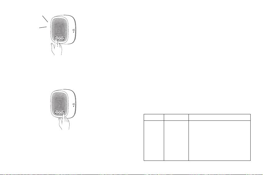
Press the pairing buon and you will hear a ‘Beep’ sound.
- 04 - - 05 -
●
Take off the baery cover from the PIR sensor and insert
3 x AAA baeries. Reaach the baery cover and secure
with the screw.
3xAAA 1.5V
Alkaline Baery
3.3 Paring the PIR sensors with the Receiver
Now that the PIR sensor and receiver are powered, the PIR
sensor need to be paired with your receiver before the alarm
will funcon.
Place the PIR sensor and receiver nearby each other and
ensure the PIR sensor is turned away from you.
A. When the receiver becomes powered, a ‘dingdong’ will
sound to indicate the receiver is on.
B. Press the pairing buon unl the ‘BEEP’ sound plays. The
Zone LED indicator will display the selected zone number.
Press the Melody/Next buon unl the desired zone
number is displayed.
‘BEEP’
Press the Melody/Next buon
The selected zone number will light up
21
3 4
- 06 - - 07 -
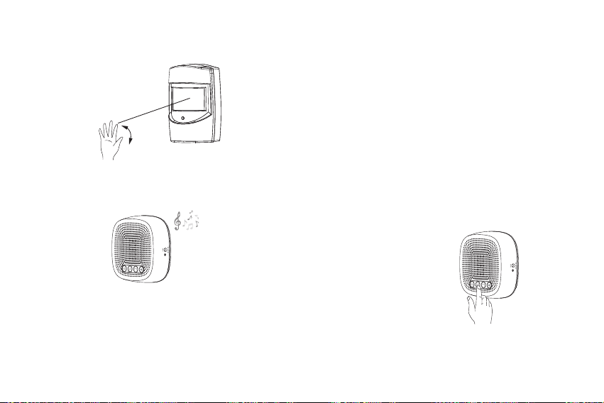
C. Wave your hand before the PIR sensors to acve the PIR
sensor. You will hear an alarm/melody sound if pairing is
successful.
Wave hand in in front of the PIR sensor to acvate it, the
working indicator will turns on meaning the PIR sensor
was acvated.
A alarm/melody sound will play indicator that pairing is
successful.
You also can acvate the PIR sensor again to confirm it has
been added to the receiver already.
Same steps to add more sensors to the alarm receiver. The
driveway alarm receiver can support up to 4 sensors per zone,
for a total of 16 sensors per receiver.
Note:
Pairing mode will stay acve for 15 seconds aer the
sound of the ‘Beep’. If you don’t hear an alarm/melody sound,
repeat the pairing process and make sure that the selected
zone number is on when you acvate the sensor.
Note that only one solar LED light or PIR sensor for one zone
can be paired at a me.
3.4 Choose an Alarm Melody for the Sensors
The alarm melody for Zone 1 can be customized, while melodies
for Zone 2, Zone 3 and Zone 4 are fixed and cannot be changed.
Zone 1: Press the Melody buon to cycle through the available
melodies and stop on the desired.
melody to select it.
Zone 2: DingDong melody. As the “dingdong” sound is similar
to a doorbell melody, we suggest the Zone 2 sensor be
placed in a low security area such as the entrance of
the garden.
Zone 3: Dripping melody. This also is a nice melody for a
low security area, such as the driveway.
Zone 4: Alarm melody. This sound is tailored for high security
areas. We suggest the sensor for Zone 4 be placed in
areas where trespassing is a possibility.
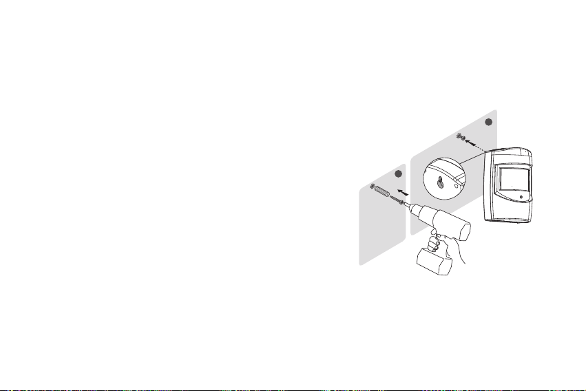
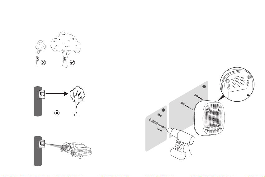
3.5 Installing the PIR sensor
It is recommended to mount the PIR sensor at least 3-4
(1m) above the ground on a sturdy, non-metal surface
(i.e. a wall, wooden post, or tree near your door/driveway)
with the PIR sensor detect area pointed straight out over
the area you wish to cover (such as up your driveway
looking towards your house). Mounng at this height and
direcon will decrease or eliminate false alarms from small
animals, enable sensing of a larger area, and avoid
unwanted alarms caused by nearby lawns / roads.
The PIR sensor can be placed with e to fix it on a the
wanted place and also can installed with the supplied
screws.
Install the PIR sensor using the supplied screws:
●
Use a pencil to mark the locaon of the two mounng
holes on the surface where the PIR sensor base will be
installed.
●
If installing on a wooden surface, only the included screws
need to be used. Drill out pilot holes to help prevent
stripping of the screws and hold the sensor more securely.
- 08 - - 09 -
1
2
●
If installing on any other surface, such as brick or stone,
use the included wall plugs with the screws. To do this,
drill out pilot holes, then gently tap the wall plugs into the
pilot holes using a hammer unl the wall plug are flush
with the mounng surface.
●
Push the screws into the wall plugs, then hang PIR sensors
on the screws.
- 10 - - 11 -
3.6 Installing the Receiver
The receiver can be placed on any indoor flat panel or mounted
on any type of surface using the supplied screws.
1. Use a pencil to mark the locaon of the two mounng holes
on the surface where the receiver will be installed.
2. Drill out the pilot holes and gently tap the wall plugs into the
pilot holes using a hammer unl the wall plugs are flush with
the mounng surface.
3. Push the screws into the wall plugs, then hang the receiver
on the screws.
1
2
Note:
1. Please install the sensors ghtly to ensure the posion
and the direcon will not be easy moved by wind.
2. Please point the PIR sensor towards a open field.
(not towards the trees or bushes)
3. Please point the sensor to the main detecng area. Like
the entrance of the driveway or walkway etc.

- 12 - - 13 -
Flash Mode --- Press the Alert Mode buon twice; only the
Zone LED indicator will turn on.
Sound+ Flash Mode --- Press the Alert Mode a third me;
a Beep sound will play and the Zone LED indicator will turn
on. This Alert Mode is the factory default seng.
Note:
●
When you do not want to be disturbed or the user has a
hearing problem, we suggest seng the alarm receiver’s
Alert Mode to “Flash” mode.
●
When one PIR sensor is triggered, the LED indicator will
display the zone number and the alarm melody will sound.
When more than one sensor from 2 different zones is
triggered at the same me, the receiver’s LED indicator will
display both zone numbers alternavely for about 20 seconds,
while the alarm melody of the more recent triggered zone
will play. During this 20 seconds, if other PIR sensors triggered,
the receiver will not alarm.
3.8 Manufacture Default Sengs
If the receiver rings but the PIR sensor has not been triggered,
or the PIR sensor interferes with another receiver, it may be
necessary to wipe the current pairings and pair again.
To return the receiver back to default seng, press and hold
the pairing buon 3 seconds unl a ‘BEEP’ is hear. The receiver
will BEEP five mes and the LED indicator will display “8” to
indicate all pairings have been removed from the receiver.
Aer unpairing, the receiver can be paired again to a PIR
sensor.
Note:
The working distance for the receiver and PIR sensor is
300m (1000) without obstacle, Always test the working
distance between the PIR sensor and receiver before
installing these units.
3.7 Selecng the Alert Mode for the Receiver
When the PIR sensors are triggered, the alarm receiver can
alert you with an auditory sound, a flashing zone LED
indicator, or sound and flashing zone LED indicator together.
These are referred to as Sound, Flash, and Sound +Flash
modes.
To select an alert mode, press the Alert Mode buon to cycle
through the modes. Stop pressing the Alert Mode buon when
you reach the alert mode you want to set.
The factory default seng is Sound+ Flash mode.
Sound Mode --- Press the Alert Mode buon once; a Beep
sound will play but the Zone LED indicator will not turn on.
- 14 - - 15 -
‘BEEP’
3.9 Change the Volume of the Melody
Press the volume buon to change the ringtone’s volume.
Each press will change the volume to one of six levels. Stop
pressing the volume buon your desired volume level is
reached.
4. Specificaon:
Receiver:
●
Power supply: DC 4.5V (3 x AA baeries or by an adapter)
●
Wireless frequency: 433MHz±20KHz
●
Operang range: 300m/1000 (without obstacles)
●
Receiver’s ring volume: Over 100dB within 0.5m/1.6
●
Working temperature: -20°C ~ 50°C
PIR Sensor:
●
Power supply: DC 4.5V (3 x AAA baeries)
●
Detecng Distance: up to 6 meters
●
Detecng Angle: 60 degrees
●
Working Temperature: -20°C ~ 45°C
●
Waterproof: IP44
5. Troubleshoong:
Most issues that arise can easily be resolved by changing
sengs or reseng the driveway alarms. Use the table
below to find your exact issue and possible soluon for it.
SoluonIssue Cause
Confirm that the receiver/sensors
are on. The receiver should play a
melody when the melody buon
is pressed.
The LED indicator on the sensor
will turn on when it is acvated.
The alarm
is not
being set
off
Receiver /
Sensors not
powered on

- 16 - - 17 -
SoluonIssue Cause
Inconsistent
alarms
The PIR sensor on which
transming frequency is 433MHz
and its range can be affected by
metal, concrete, and other
interfering signals from electronic
appliances with the same frequency.
Receivers or sensors mounted close
to siding or stucco may have
inconsistent signal recepon.
Avoid placing the PIR sensor and
receiver near the above menoned
materials and electronics.
Signal
interference
Low baeries can reduce a PIR
sensor’s working range. Replace
the sensor’s baeries.
Low power
supply in
the PIR
sensor
SoluonIssue Cause
The alarm
is not
being set
off
Follow instrucon to pair the PIR
sensor with the receiver.
PIR sensor
not paired
with receiver
Reset all sensors
(see Manufacture default sengs).
Incorrect
sensor
sengs
Reset all PIR sensor and pair them
again.
Inconsistent
alarms
PIR sensor
not paired
properly
The working distance between
sensor and receiver is about
1000 (300m). If the PIR sensor
acvated, but no alarm plays on
the receiver, then the PIR sensor
is out of range. If there is heavy
interference between PIR sensor
and receiver, if using in a heavily
wooded area, or signal passes
through mulple buildings, the
maximum effecve range will be
reduced.
Move the PIR sensor and receiver
closer together unl alerts are
received consistently.
PIR Sensor
is out of
range of
receive /
Interference
issue

6. Quesons?
If you have any quesons about your wireless driveway alarm,
you can freely contact our 24H Customer Service at:
Sincerely
The Tilvision Team
- 18 -