Loading ...
Loading ...
Loading ...
I Installation Instructions
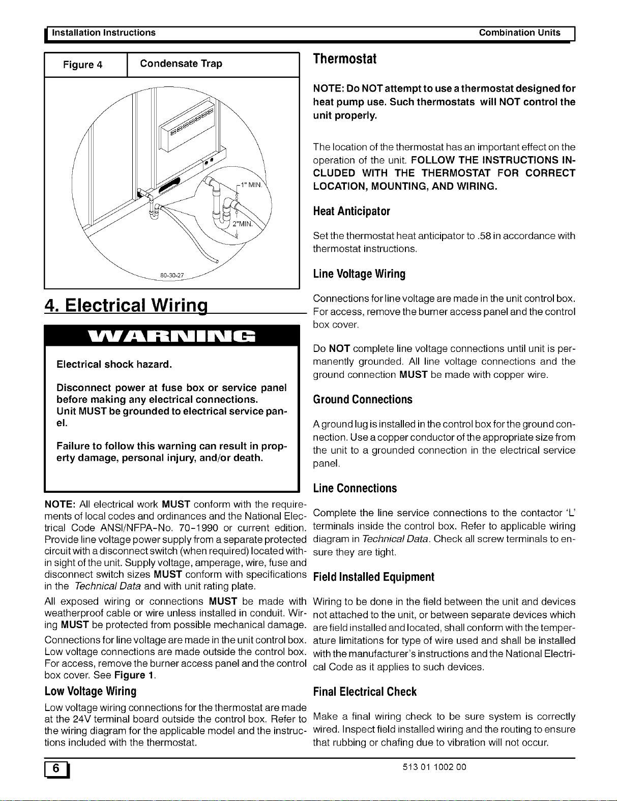
Figure 4 Condensate Trap
80-30-27
Thermostat
Combination Units I
NOTE: Do NOT attempt to use a thermostat designed for
heat pump use. Such thermostats will NOT control the
unit properly.
The location of the thermostat has an important effect on the
operation of the unit. FOLLOW THE INSTRUCTIONS IN-
CLUDED WITH THE THERMOSTAT FOR CORRECT
LOCATION, MOUNTING, AND WIRING.
HeatAnticipator
Set the thermostat heat anticipator to .58 in accordance with
thermostat instructions.
LineVoltage Wiring
4. Electrical Wiring
Connections for line voltage are made in the unit control box.
For access, remove the burner access panel and the control
box cover.
Electrical shock hazard.
Disconnect power at fuse box or service panel
before making any electrical connections.
Unit MUST be grounded to electrical service pan-
el.
Failure to follow this warning can result in prop-
erty damage, personal injury, and/or death.
NOTE: All electrical work MUST conform with the require-
ments of local codes and ordinances and the National Elec-
trical Code ANSI/NFPA-No. 70-1990 or current edition.
Provide line voltage power supply from a separate protected
circuit with a disconnect switch (when required) located with-
in sight of the unit. Supply voltage, amperage, wire, fuse and
disconnect switch sizes MUST conform with specifications
in the Technical Data and with unit rating plate.
All exposed wiring or connections MUST be made with
weatherproof cable or wire unless installed in conduit. Wir-
ing MUST be protected from possible mechanical damage.
Connections for line voltage are made in the unit control box.
Low voltage connections are made outside the control box.
For access, remove the burner access panel and the control
box cover. See Figure 1.
LowVoltageWiring
Low voltage wiringconnections for the thermostat are made
at the 24V terminal board outside the control box. Refer to
the wiring diagram for the applicable model and the instruc-
tions included with the thermostat.
Do NOT complete line voltage connections until unit is per-
manently grounded. All line voltage connections and the
ground connection MUST be made with copper wire.
GroundConnections
A ground lug is installed inthe control box for the ground con-
nection. Use a copper conductor of the appropriate size from
the unit to a grounded connection in the electrical service
panel.
Line Connections
Complete the line service connections to the contactor 'L'
terminals inside the control box. Refer to applicable wiring
diagram in Technical Data. Check all screw terminals to en-
sure they are tight.
FieldInstalled Equipment
Wiring to be done in the field between the unit and devices
not attached to the unit, or between separate devices which
are field installed and located, shall conform with the temper-
ature limitations for type of wire used and shall be installed
with the manufacturer's instructions and the National Electri-
cal Code as it applies to such devices.
FinalElectrical Check
Make a final wiring check to be sure system is correctly
wired. Inspect field installed wiring and the routing to ensure
that rubbing or chafing due to vibration will not occur.
E_ 513 01 1002 00
Loading ...
Loading ...
Loading ...