Loading ...
Loading ...
Loading ...
I Combination Units
CAUTION
Unit will NOT operate properly unless it is installed level
front to rear and side to side.
RooftopInstallation
The existing roof structure MUST be adequate to support the
weight of the unit or the roof MUST be reinforced. Check the
weight of the unit in relation to the roof structure and local
building codes or ordinances and reinforce if necessary.
The unit MUST be situated to provide safe access for servic-
ing. Support for the unit MUST be level and may consist of a
platform or a combination of platform and roof beams or
curb. The platform may be constructed of combustible mate-
rial (wood only), or covered with Class A, B or C roof cover-
ing.
Hoisting
The unit should be hoisted with two lifting slings. Attach the
slings to rigging shackles that have been hooked through
holes in the base rail.
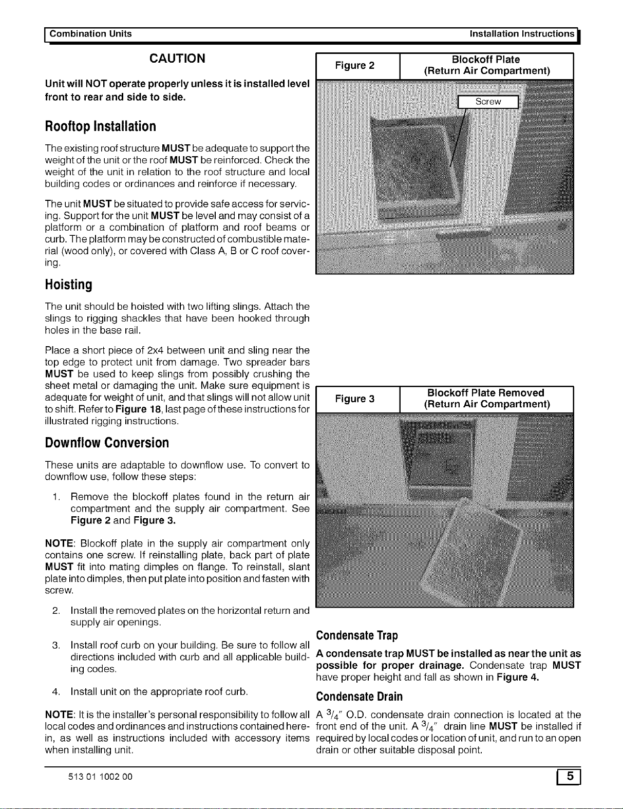
Figure 2
Installation Instructions
Blockoff Plate
(Return Air Compartment)
Screw
Place a short piece of 2x4 between unit and sling near the
top edge to protect unit from damage. Two spreader bars
MUST be used to keep slings from possibly crushing the
sheet metal or damaging the unit. Make sure equipment is
adequate for weight of unit, and that slings will not allow unit
to shift. Refer to Figure 18, last page of these instructions for
illustrated rigging instructions.
DownflowConversion
I Figure 3
Blockoff Plate Removed
(Return Air Compartment)
These units are adaptable to downflow use. To convert to
downflow use, follow these steps:
1. Remove the blockoff plates found in the return air
compartment and the supply air compartment. See
Figure 2 and Figure 3.
NOTE: Blockoff plate in the supply air compartment only
contains one screw. If reinstalling plate, back part of plate
MUST fit into mating dimples on flange. To reinstall, slant
plate into dimples, then put plate into position and fasten with
screw.
2. Install the removed plates on the horizontal return and
supply air openings.
CondensateTrap
3. Install roof curb on your building. Be sure to follow all
directions included with curb and all applicable build- A condensate trap MUST be installed as near the unit as
ing codes, possible for proper drainage. Condensate trap MUST
have proper height and fall as shown in Figure 4.
4. Install unit on the appropriate roof curb. Condensate Drain
NOTE: It is the installer's personal responsibility to follow all A 3/4" O.D. condensate drain connection is located at the
local codes and ordinances and instructions contained here- front end of the unit. A 3/4" drain line MUST be installed if
in, as well as instructions included with accessory items required by local codes or location of unit, and run to an open
when installing unit. drain or other suitable disposal point.
513 01 1002 00 E_]
Loading ...
Loading ...
Loading ...