Loading ...
Loading ...
Loading ...
I Combination Units Installation Instructions
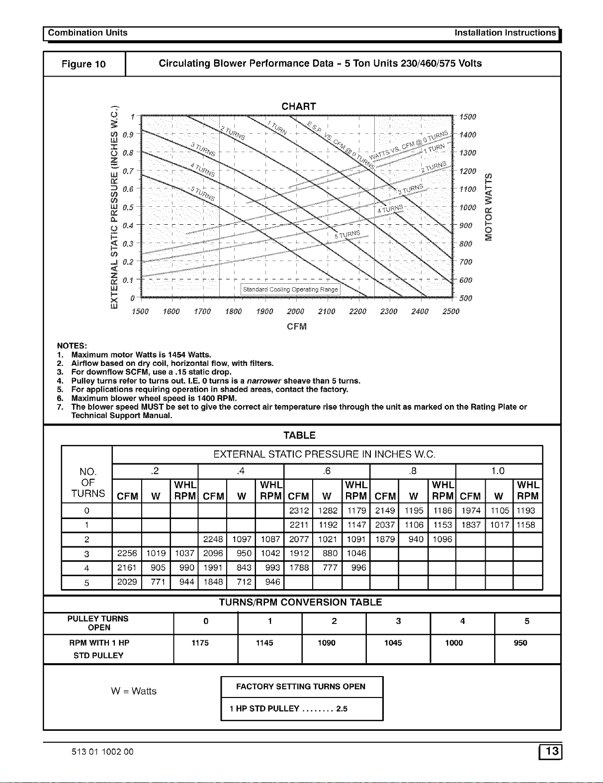
Figure 10 Circulating Blower Performance Data - 5 Ton Units 230/460/575 Volts
0.9
LL!
0 0.8
g
w 0.7
0.6
0.5
0,,
0.4
0.3
.J 0.2
Z
0.1
LJJ
p-
X 0
uJ
I I
--------r--
CHART
Standard Cooling Operating Range
t500
1400
t300
L t200
p.
L 1100 P
L 1000
0
L900 S
L800
L 700
600
500
1500 t600 1700 1800 t900 2000 2100 2200 2300 2400 2500
CFM
NOTES:
1. Maximum motor Watts is 1454 Watts.
2. Airflow based on dry coil, horizontal flow, with filters.
3. For downflow SCFM, use a .15 static drop.
4. Pulley turns refer to turns out. I.E. 0 turns is a narrower sheave than 5 turns.
5. For applications requiring operation in shaded areas, contact the factory.
6. Maximum blower wheel speed is 1400 RPM.
7. The blower speed MUST be set to give the correct air temperature rise through the unit as marked on the Rating Plate or
Technical Support Manual.
TABLE
NO.
OF
TURNS
0
1
2
3
4
5
EXTERNAL STATIC PRESSURE IN INCHES W.C.
.2 .4 .6 .8 1.0
WIlL WIlL WIlL WIlL WIlL
CFM W RPM CFM W RPM CFM W RPM CFM W RPM CFM W RPM
2312 1282 1179 2149 1195 1186 1974 1105 1193
2211 1192 1147 2037 1106 1153 1837 1017 1158
2248 1097 1087 2077 1021 1091 1879 940 1096
2256 1019 1037 2096 950 1042 1912 880 1046
2161 905 990 1991 843 993 1788 777 996
2029 771 944 1848 712 946
TURNS/RPM CONVERSION TABLE
PULLEY TURNS 0 1 2 3 4 5
OPEN
RPM WITH 1 HP 1175 1145 1090 1045 1000 950
STD PULLEY
W = Watts
I
FACTORY SETTING TURNS OPEN I
I
1 HP STD PULLEY ........ 2.5
513 01 1002 O0 _f_
Loading ...
Loading ...
Loading ...