Loading ...
Loading ...
Loading ...
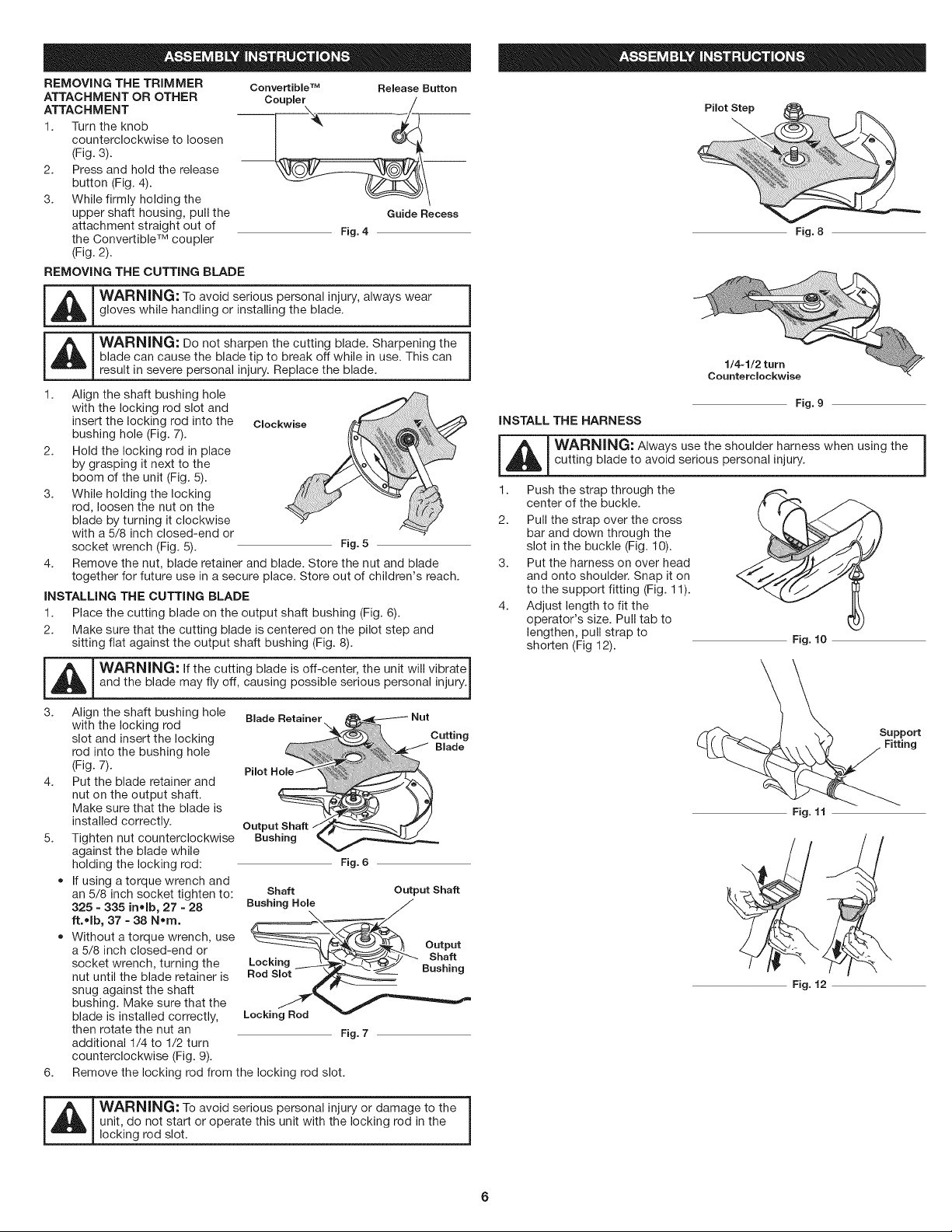
REMOVING THE TRIMMER ConvertibleTM Release Button
ATTACHMENT OR OTHER Coupler
ATTACHMENT _1
1. Turn the knob
counterclockwise to loosen
(Fig. 3).
2. Press and hold the release
button (Fig. 4).
3. While firmly holding the
upper shaft housing, pull the Guide Recess
attachment straight out of
Fig. 4
the Convertible TM coupler
(Fig. 2).
REMOVING THE CUTTING BLADE
m
_L_ ARNING: To avoid serious personal injury, always wear
gloves while handling or installing the blade.
_ ARNING: Do not sharpen the cutting blade. Sharpening the
blade can cause the blade tip to break off while in use. This can
result in severe personal injury. Replace the blade.
1. Align the shaft bushing hole
with the locking rod slot and
insert the locking rod into the Clockwise
bushing hole (Fig. 7).
Hold the locking rod in place
by grasping it next to the
boom of the unit (Fig. 5).
While holding the locking
rod, loosen the nut on the
blade by turning it clockwise
with a 5/8 inch closed-end or
socket wrench (Fig. 5). Fig. 5
2.
3.
4. Remove the nut, blade retainer and blade. Store the nut and blade
together for future use in a secure place. Store out of children's reach.
INSTALLING THE CUTTING BLADE
1. Place the cutting blade on the output shaft bushing (Fig. 6).
2. Make sure that the cutting blade is centered on the pilot step and
sitting flat against the output shaft bushing (Fig. 8).
_L_ ARNING: If the cutting blade is off-center, the unit will vibrate
and the blade may fly off, causing possible serious personal injury.I
I
3. Align the shaft bushing hole Blade Retainer
with the locking rod
slot and insert the locking
rod into the bushing hole
(Fig. 7).
4. Put the blade retainer and
nut on the output shaft.
Make sure that the blade is
installed correctly.
5. Tighten nut counterclockwise
against the blade while
holding the locking rod: Fig. 6
• If using a torque wrench and
an 5/8 inch socket tighten to:
325 - 335 inolb, 27 - 28
ft.olb, 37 = 38 Norn.
• Without a torque wrench, use
a 5/8 inch closed-end or
socket wrench, turning the
nut until the blade retainer is
snug against the shaft
bushing. Make sure that the
blade is installed correctly,
then rotate the nut an Fig. 7
additional 1/4 to 1/2 turn
counterclockwise (Fig. 9).
Output Shaft
Bushing
Cutting
Blade
Shaft Output Shaft
Bushing Hole
6. Remove the locking rod from the locking rod slot.
_ ARNING: To avoid serious personal injury or damage to the
unit, do not start or operate this unit with the locking rod in the
locking rod slot.
Pilot Step L
i:
Fig. 8
Counterclockwise
Fig. 9
iNSTALL THE HARNESS
_ ARNING: Always use the shoulder harness when using the
cutting blade to avoid serious personal injury.
1. Push the strap through the
center of the buckle.
2. Pull the strap over the cross
bar and down through the
slot in the buckle (Fig. 10).
3. Put the harness on over head
and onto shoulder. Snap it on
to the support fitting (Fig. 11).
4. Adjust length to fit the
operator's size. Pull tab to
lengthen, pull strap to
shorten (Fig 12).
Fig. 10
Support
Ing
Fig. 11
Fig. 12
Loading ...
Loading ...
Loading ...