Loading ...
Loading ...
Loading ...
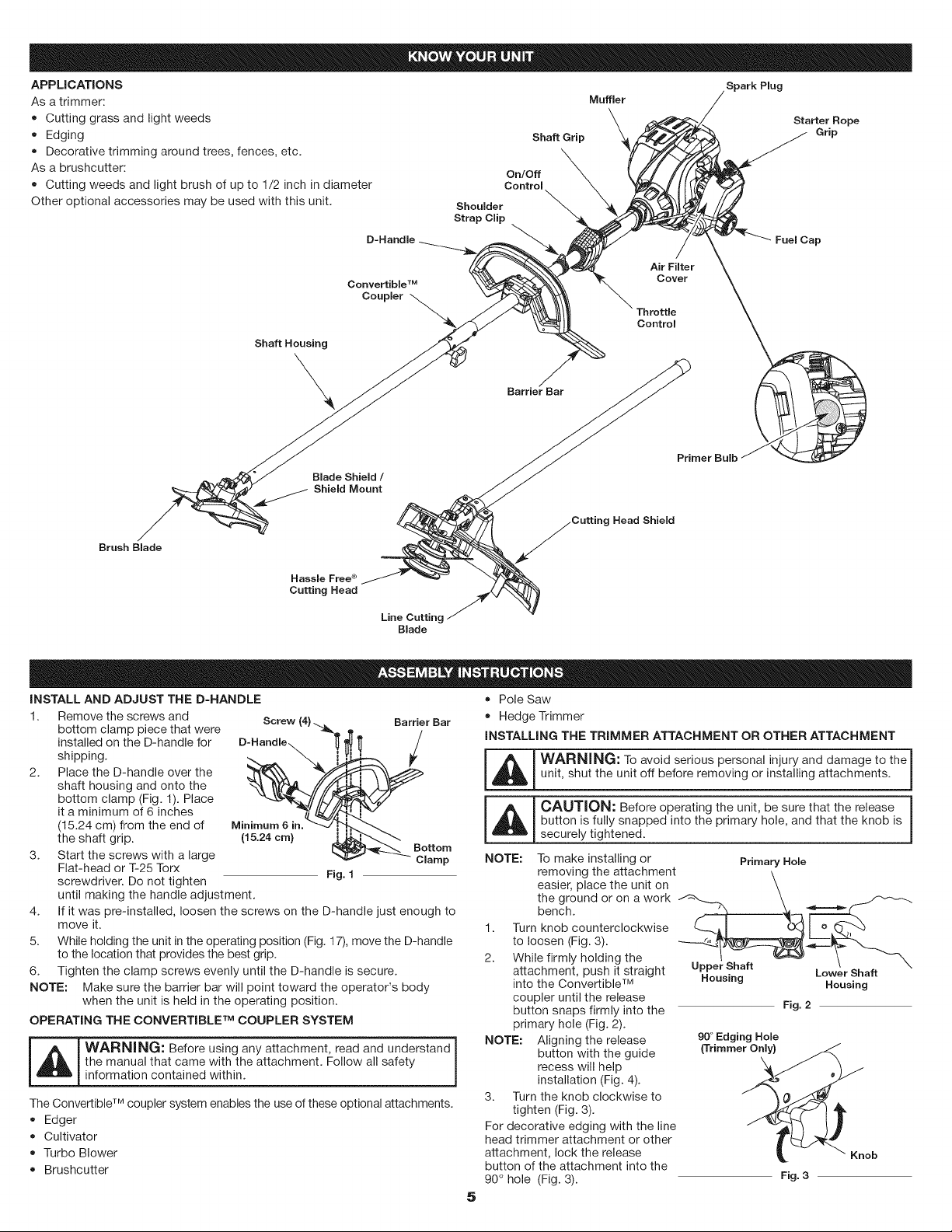
APPLICATIONS
Asatrimmer:
• Cuttinggrassandlightweeds
Edging
Decorativetrimmingaroundtrees,fences,etc.
Asabrushcutter:
Cuttingweedsandlightbrushofupto1/2inchindiameter
Otheroptionalaccessoriesmaybeusedwiththisunit.
D-Handle
Shaft Grip
On/Off
Control
Shoulder
Strap Clip
Spark Plug
Muffler
Starter Rope
Grip
Fuel Cap
Convertible TM
Coupler
Air Filter
Cover
Throttle
Control
Shaft Housing
\
Barrier Bar
Brush Blade
Blade Shield /
Shield Mount
Hassle Free ®
Cutting Head
Line Cutting
Blade
Primer Bulb
Head Shield
iNSTALL AND ADJUST THE D-HANDLE
1. Remove the screws and Screw (4).
bottom clamp piece that were
installed on the D-handle for
shipping.
2. Place the D-handle over the
shaft housing and onto the
bottom clamp (Fig. 1). Place
it a minimum of 6 inches
(15.24 cm) from the end of
the shaft grip.
3. Start the screws with a large
Flat-head or T-25 Torx
screwdriver. Do not tighten
Minimum 6 in.
(15.24 cm)
Barrier Bar
/
Bottom
Clamp
Fig. 1
until making the handle adjustment.
4. If it was pre-installed, loosen the screws on the D-handle just enough to
move it.
5. While holding the unit in the operating position (Fig. 17), move the D-handle
to the location that provides the best grip.
6. Tighten the clamp screws evenly until the D-handle is secure.
NOTE: Make sure the barrier bar will point toward the operator's body
when the unit is held in the operating position.
OPERATING THE CONVERTIBLE TM COUPLER SYSTEM
_ ARNING: Before using any attachment, read and understand
the manual that came with the attachment. Follow all safety
information contained within.
The Convertible TM coupler system enables the use of these optional attachments.
• Edger
• Cultivator
• Turbo Blower
• Brushcutter
5
• Pole Saw
• Hedge Trimmer
INSTALLING THE TRIMMER ATTACHMENT OR OTHER ATTACHMENT
I A I WARNING: To avoid serious personal injury and damage to the I
_ unit, shut the unit off before removing or installing attachments.
!_!CAUTION:Beforeoperatingtheunit, besurethattherelease I
button is fully snapped into the primary hole, and that the knob is
securely tightened.
NOTE:
1.
2.
To make installing or Primary Hole
removing the attachment _,
easier, place the unit on
the ground or on a work
bench.
Turn knob counterclockwise--_" '____t__, rq r------_
to loosen (Fig. 3).
While firmly holding the
attachment, push it straight Upper Shaft
into the Convertible TM
coupler until the release
button snaps firmly into the
primary hole (Fig. 2).
NOTE: Aligning the release
button with the guide
recess will help
installation (Fig. 4).
3. Turn the knob clockwise to
tighten (Fig. 3).
For decorative edging with the line
head trimmer attachment or other
attachment, lock the release
button of the attachment into the
90 ° hole (Fig. 3).
Housing LowerShaft
Housing
90 ° Edging Hole
(Trimmer Only)
Fig. 2
Loading ...
Loading ...
Loading ...