Loading ...
Loading ...
Loading ...
Part number 550-100-325/0419
92
AquaBalance
®
Series 2 Wall Mount Gas-fired Water Boiler – Boiler Manual
37 Troubleshooting(continued)
Control diagnosis
1. The boiler control is equipped with an advanced self-diagnosis system. In case of a boiler fault, the display will flash together with
the fault symbol (see Table 3 or Table 4) indicating the fault code.
2. Certain faults cause permanent boiler shutdowns (marked with the letter “A” see Table 3): to restore operation, press the RESET
button (Item 6 - Figure 80, page 62) for 1 second or RESET on the optional remote timer control if installed; if the boiler fails
to start, it is necessary to firstly eliminate the fault.
3. Other faults (indicated with the letter “F”, see Table 4, page 95) cause temporary shutdowns that are automatically reset as soon
as the value returns within the boiler’s normal operating range.
Protection and error conditions
1. Several checks are included to protect the boiler and its environment. Severe error will cause a lockout condition which can only
be cleared by the reset key at the boiler front panel.
2. Non severe errors faults will reset as soon as the cause of the problem disappears/corrects themselves.
3. Number of reset action is limited to 5 in 24 hours. By powering off/on, it is possible to reset this limitation: in this way, another
5 reset per 24 hour can be done.
4. Error codes can be divided in 2 groups:
a. Manual Reset type lock-out codes – “A” codes: (which blocks the heat demand - Press reset button for 1 second to reset).
b. Automatic Reset type lock-out codes – “F” codes: (cause temporary shutdowns that are automatically reset as soon as the
value returns within the boilers normal working range).
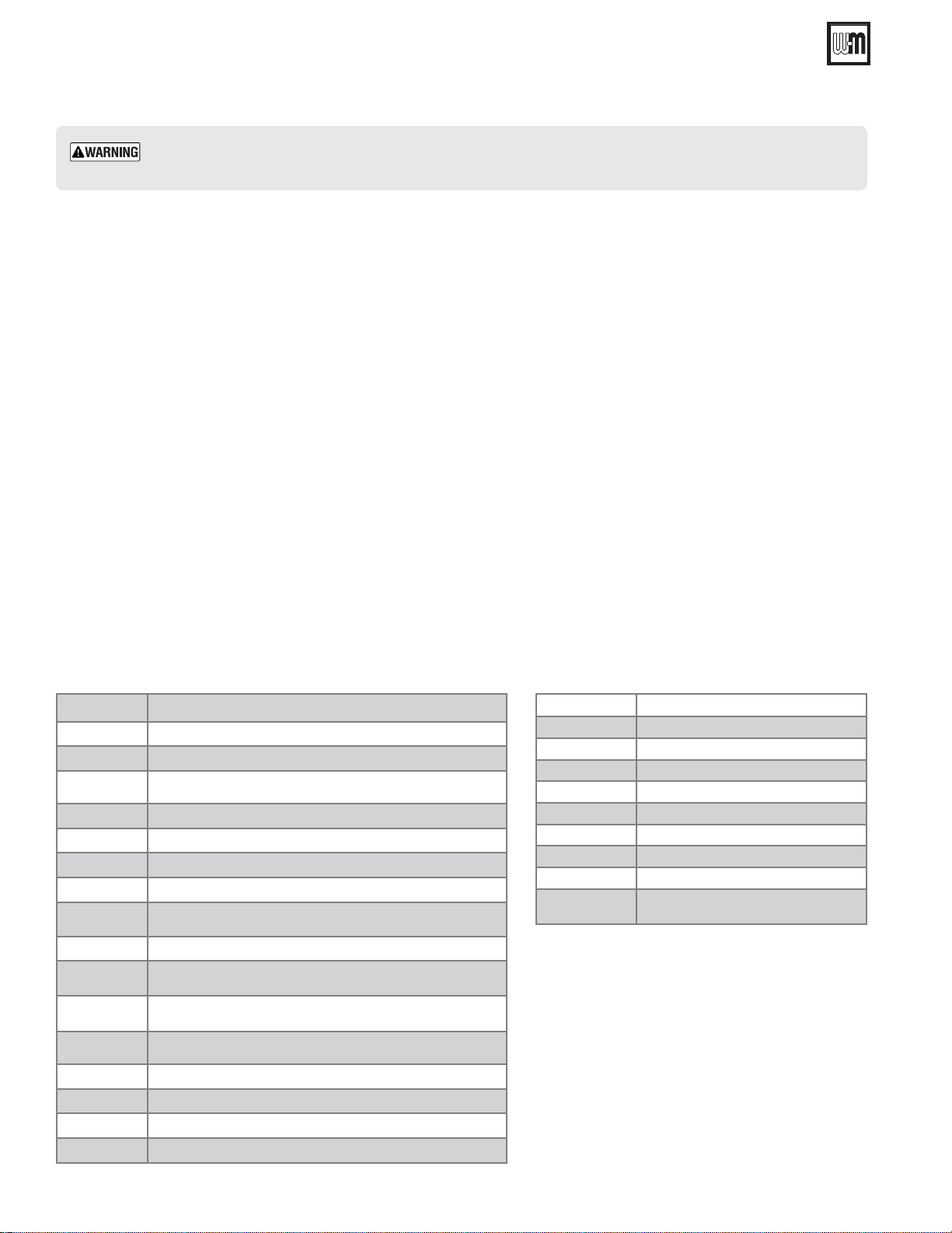
Hard Lock-out condition codes
Lock out condition is given with the capital “A” (alarm) on the status display and error code on the
temperature display. The meaning of the error numbers are as follow:
-
Table 3 A
A01 No burner ignition after ve attempts
A02 False ame indication
A03
High limit protection: pump does not run or no
water circulation
A04 F07 repeated 3 times in the last 24 hours
A05 No frequency feedback from fan after 1 hour
A06 6 times ame loss in 4 minutes time frame
A16 Outside sensor is not connected
A23
Nominal water pressure not reached within
maximum allowed time
A26 F40 repeated 3 times in the last hour
A41
Temperature sensor not or bad connected to
the pipe (CH mode)
A42
Too high difference between two CH supply water
temperature sensors
A44
Temperature sensor not or bad connected to
the pipe (DHW mode)
A61 Flame circuit error
A62 Gas valve circuit
A63 E2 prom error
A65 ADC circuit error
Abbreviation
ADC Analog Digital Converter
CH Central Heating
DHW Domestic Hot Water
LP Liqueed Petroleum (Propane) Gas
LWCO Low Water Cut Off
MMI Machine Interface- Control Interface
OTC Outdoor Temperature Sensor
PCB Printed Circuit Board - Control board
PWM
Pulse width modulation - Used for
modulating pumps and motors
Loading ...
Loading ...
Loading ...