Loading ...
Loading ...
Loading ...
Part number 550-100-325/0419
83
AquaBalance
®
Series 2 Wall Mount Gas-fired Water Boiler – Boiler Manual
At Minimum Rate:
1. Remove T-40 cap, see Figure 108, page 82, for Offset screw
adjustment. Adjust the boiler to minimum output and allow
the boiler to stabilize.
2. Now adjust the offset pressure setting (Figure 109 - screw B)
Torx (T-40 male driver) until the CO
2
is at the correct SET-
TING LEVEL (see Figure 110), confirm that the CO/CO
2
ratio is within limits (clockwise to increase gas).
33 Startup — nal checks
(continued)
Re-check the Maximum and Minimum
Rate
3. After the gas valve is adjusted, please check one more
time that the Maximum and Minimum rate CO/CO
2
to ensure that the values have not changed.
4. In the event that the CO
2
setting level with an acceptable
CO/CO
2
ratio cannot be obtained please contact your
Weil-McLain Technical Support.
❏
1. Operate the boiler on HIGH fire.
2. A leak would appear as vapor on the surface of the
mirror.
3. If there is any indication of a leak at any joint, immedi-
ately shut down the boiler.
a. If possible, tighten the retaining screws or nuts
(without over-tightening).
b. If this does not correct the problem, disassemble
the components where the leak appeared. Use the
procedures given in the Maintenance section of
this manual.
c. When disassembling components, inspect gaskets to
see if there is damage. Replace any damaged gasket.
d. Contact your Weil-McLain Technical Support if the
problem cannot be addressed with the information
provided in this manual.
❏
1. After the boiler has been installed, turn off the boiler.
2. Shut off the manual gas valve located on the gas line to
cut flow of fuel to the boiler.
3. Turn on the boiler. It will start to ignite and a “d3” code
will flash. After the “d3” code flash for some time the
boiler will go into a Lockout condition and a “A01” code
will show in the display. It means that the boiler tried to
ignite without success (code “d3”) for three (3) times
and when into Lockout mode(code “A01”). This means
that the ignition system safety device worked properly.
4. Open the manual gas valve located on the gas line to
resume fuel supply to the boiler.
5. Hit the “” button once to Clear the Lockout code
“A01”.
Figure 110Minimum rate combustion values –
measured values must be within the ranges
given below
Adjust in steps of no more than 1/8 of a turn and
wait 1 minute after each adjustment to allow the
setting to stabilize. Turning the screw too far will
cause the adjustment to reverse behavior.
Combustion Range
Boiler Model
CO/(PPM) CO
2
NG % CO
2
LP %
AB-80
20
AB-120
20
AB-155
7
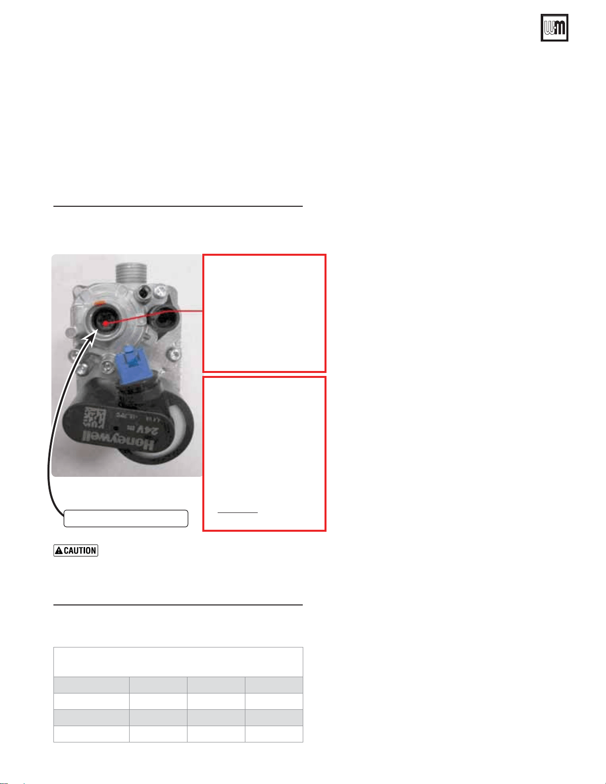
Figure 109Offset
Offset Regulating screw
Test at MIN. Power 00%
Turn clockwise (open gas)
for “MA gas ow”
Turn counter-clockwise
(close gas)
for “MIN gas ow”
Rough start point
For LP Start up ONLY
Adjust gas valve
LOW FIRE
screw on left with
Allen wrench
turn
Counter-Clock wise
- turn.
Final Combustion values
MUST BE checked with
Combustion Analyzer.
B
Loading ...
Loading ...
Loading ...