Loading ...
Loading ...
Loading ...
-7-
SPECIAL MOBILE HOME REQUIREMENTS
• WARNING! - Do not install in a sleeping room
• CAUTION! - The structural integrity of the mobile home oor,
wall, and ceiling/roof must be maintained.
In addition to the previously detailed installation requirements,
mobile home installations must meet the following requirements:
• This stove must be securely fastened to the oor of the
mobile home through the two holes in the rear of the stove
using two, 1/4” lag bolts that are long enough to go through
both a hearth pad, if used, and the oor of the home.
• The heater must be electrically grounded to the steel chassis of the mobile home with 8 GA copper wire using
a serrated or star washer to penetrate paint or protective coating to ensure grounding.
• Vent must be 3 or 4-inch “PL” Vent and must extend a minimum or 36” (914mm) above the roof line of the
mobile home and must be installed using a UL listed ceiling re stop and rain cap.
• When moving your mobile home, all exterior venting must be removed while the mobile home is being
relocated. After relocation, all venting must be reinstalled and securely fastened.
• Outside Air is mandatory for mobile home installation. See Outside Air Supply section and your dealer for
purchasing.
• Check with your local building ofcials as other codes may apply.
PREPARATION
Factory packaging must be removed, and some minor assembly work is required prior to installation. Access to
the rear of the stove is necessary. The circuit board/control panel must be unpacked and installed in the side
panel of the unit (see installation instructions provided with the circuit board).
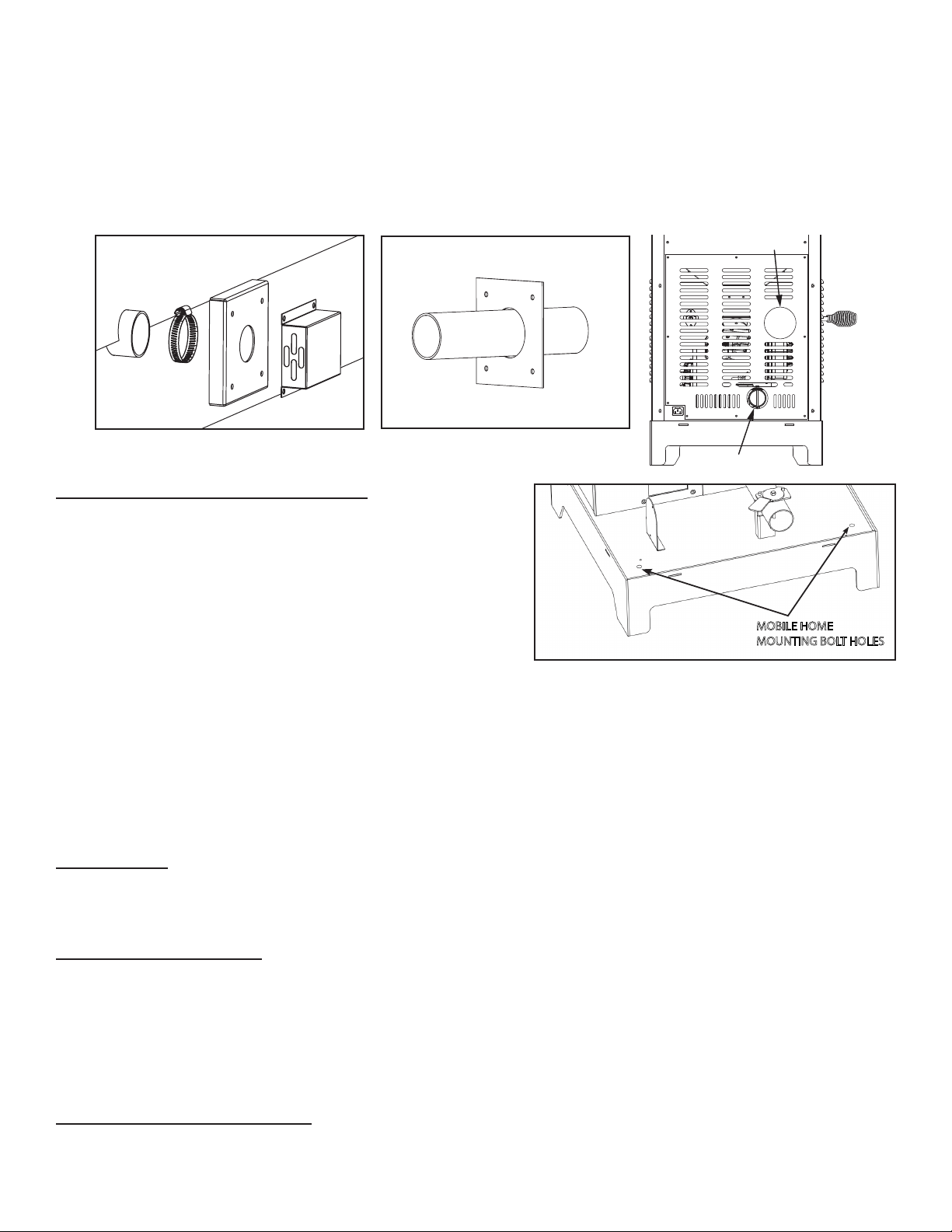
COMBUSTION AIR SUPPLY
If outdoor combustion air is supplied the heater must be attached to the structure. For a mobile home installation
the stove must be connected to an outside source of combustion air. A 2” inside diameter metallic pipe, either
exible or rigid, may be attached to the inlet at the stove’s rear. A rodent guard (minimum 1/4” wire mesh)/wind
hood must be used at the terminus. All connections must be secured and airtight by either using the appropriately
sized hose clamp and/or UL-181-AP foil tape. For mobile home installations only: 2” inside diameter pipe may
be used for the rst 5 feet of combustion air supply run. From 5 to 10 feet use 2-3/4” inside diameter pipe. No
combustion air supply may exceed 10 feet.
WHEN OUTSIDE AIR IS NOT USED
If outside air is not used, it is important that combustion air is easily available to the air inlet. A closeable outside
air register can be used in tightly insulated homes.
MOBILE HOME
MOUNTING BOLT HOLES
Figure 1
B
C
E
A
Figure 2
A
D
EXHAUST OUTLET
FRESH AIR INTAKE
6. On the Air Inlet Tube coming out of the rebox, there is a cap that must have four (4), 5/32” (0.156) diameter
holes drilled in it for the fresh air installation. The cap is on the front side of the tube just under the burnpot.
Remove burnpot. Using a long screwdriver or equivalent, knock the cap off by inserting it from the back of
the stove and pecking with a hammer. Drill holes, then replace cap and burnpot.
7. Attach one of the 2” ex hoses to the backside of the rebox, then to air inlet pipe at the back of the stove
as shown.
8. Stretch the 2” ex hose to the air inlet on the back of the stove. Attach using the other 2” hose clamp. The
hose will extend up to 4 feet in length.
Loading ...
Loading ...
Loading ...