Loading ...
Loading ...
3
BSC Installation and Operation Manual
BSC FUNCTION CHART
BSC
MADE IN U.S.A.
PREV.
SAFETY
GROUND
MUST BE
CONNECTED
OUTDOOR
TEMP
SYSTEM
PROVE
STAGE
A
STAGE
B
MENU FUNCTIONS
SELECT enters menus or accepts changes
ADJUST selects menu items or changes settings
BACK returns to previous menu
STAGE selects stage menus or next stage
PREV./NEXT steps through output status
SYSTEM
LINE
NEUTRAL
STAGE
HELP NEXT
PRESS TO
SELECT
BACK
ADJUST
A1
A2
A3
A4
A5
A6
A7
A8
A9
A10
A11
A12
B1
B2
B3
B4
NETWORK
4-20mA
SHUTDOWN
SYSTEM
TEMP
INPUTS
ACD
<A> B C D
100 53 OFF STBY
OD= 31
o
F SYS= 114
o
F
B
SYS
A
OPERATING LIMIT
OUTPUTS
CDB
T
T
123456789 1110
OUTPUT RATINGS:
120VAC, 6A RESISTIVE
1A PILOT DUTY
15A TOTAL
FOR ALL CIRCUITS
INPUT RATINGS:
115VAC 60Hz
30VA MAX
USE COPPER WIRE,
CLASS 1 WIRE ONLY
S
+
DO NOT APPLY ANY VOLTAGE
TO SENSOR TERMINAL
FULL MODULATION
SEQUENCING CONTROL
LOCKOUT
INPUTS
STAGE
C
STAGE
D
B5
B6
B7
B8
EMS INPUT
+
SIGNAL
SHIELD
12
ENCLOSED
ENERGY
MANAGEMENT
EQUIPMENT
LISTED
99RA
US
C
U
L
R
A
B
C
D
MODULATION OUTPUTS
GND mA Volt
-++
GND mA Volt
-++
GND mA Volt
-++
GND mA Volt
-++
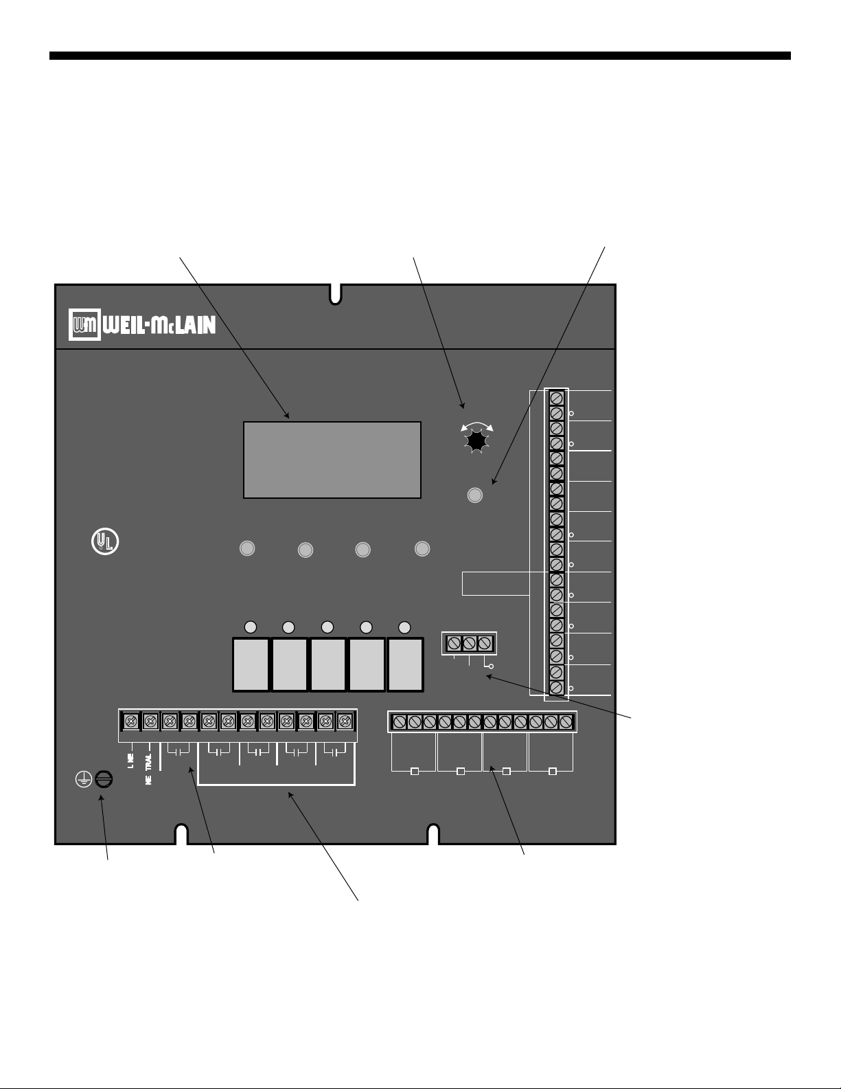
From heating system sensor
When closed, all stages
are turned off*
Setback
From outdoor sensor mounted
in the shade
Connect to remote 4-20mA
set point signal or to dry-contac
t
setback signal
If a unit is in LockOut, the BSC
will not consider it an active stag
e*
Depress the knob to move
forward through the menus and to
accept changes. To change a
setting's value, rotate the knob.
Depress the button to go back
through the menus
Digital display shows the system status,
setpoint, lead stage <in brackets>, and
status of each stage. To view and adjust
settings, press the Adjust/Select button.
Checks status of system
components*
Green Ground
screw must be
connected to
Earth Ground
System output controls
pumps, valves or other
system components.
The modulation outputs can be 0-5V, 0-10V,
1-5V, 2-10V, 4-20mA, 0-135 Ohm. Different output
boards mount on the back of the BSC to
determine the type of output.
Each N.O. output is wired in series
with the each unit's limit circuit.
Loading ...
Loading ...
Loading ...