INSTALLATION MANUAL
falmecau.com
Downdraft
90 & 120

CONGRATULATIONS
Congratulations and thank you for choosing
a Falmec rangehood.
To avoid the risks that are always present
when you use an electrical appliance it is
important that the rangehood is installed
correctly and that you read the safety in-
structions carefully to avoid misuse and ha-
zards.
We recommend that you keep this instruction
booklet for future reference and pass it on to
any future owners.
IMPORTANT INFORMATION
AFTER UNPACKING THE RANGEHOOD PLEASE REVIEW YOUR NEW ITEM TO ENSURE
THAT IT HASN’T BEEN DAMAGED IN TRANSIT OR IS MISSING ANY COMPONENTS.
FAILURE TO REPORT ANY ISSUE WITHIN 72 HOURS OF RECEIPT OF YOUR ITEM MAY
RESULT IN ADDITIONAL CHARGES.
ENVIRONMENTAL TIP
Information on disposal for users Most of the packing materials are recyclable.
Please dispose of those materials through your local recycling depot or by placing
them in a appropriate collection bin.
If you wish to discard this product, please contact your local authorities and ask for
the correct method of disposal.
TO AVOID THE RISK OF INJURY OR DAMAGE TO THE PRODUCT IT IS ESSENTIAL TO
READ THESE INSTRUCTIONS PRIOR TO INSTALLATION AND USE.
2
1081
1098
510
715
738
1026
max 400
220
92
84
341
103 275
109
90
1081
220
90
308
109
103
879
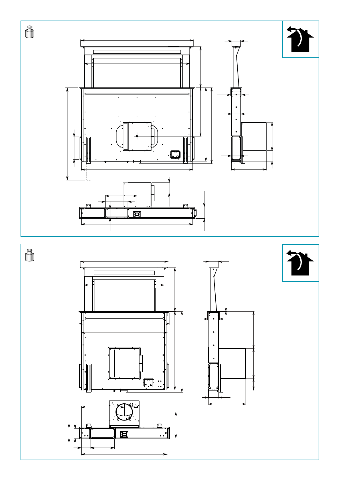
46 kg
Down draft 120
37 kg
109
84
341
92
798
726
824
738
1,5
336275
104
715
max 400
781
781
220
90
92
82
237
390,5
Down draft 90
ITALIANO
3
Down draft 90 - 120
Down draft 90 - 120
349 246
97
92
191
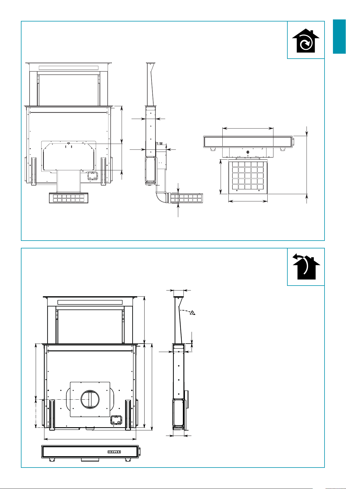
540mm quota minima
con curva 90° Falmec
321
361
471
540mm using
90° bend Falmec
781
715
max
400
738
474 241
92
1,5
84
109
IT - Motore remoto.
UK - Remote motor.
DE - Getrennt montierter Motor.
FR - Moteur monté séparément.
ES - Motor externo.
RU - Удаленный двигатель.
PL - Silnik zewnętrzny.
NL - Motor op afstand.
PT - Motor remoto.
DK - Motor monteret separat.
SE - Separat monterad motor.
FI - Etäkäyttömoottori.
NO - Fjernmotor.
4
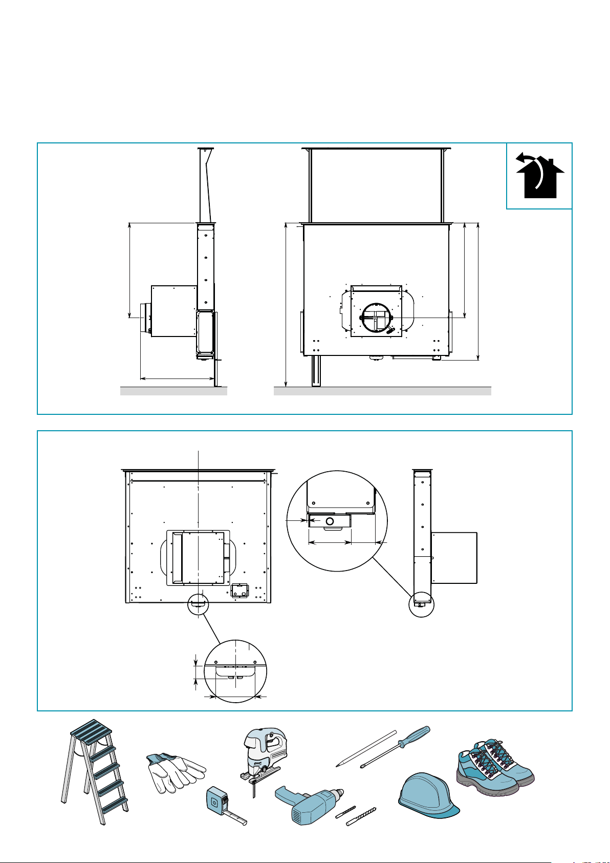
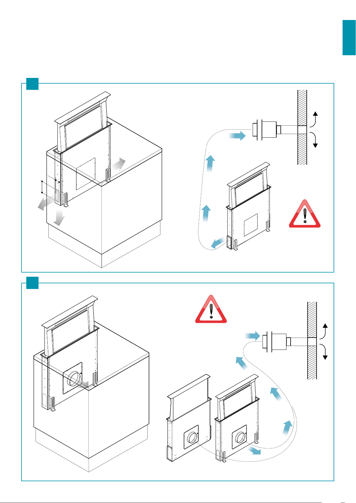
IT - Installazione con motore posteriore
UK - Installation with back motor
DE - Installation mit rückseitigem Motor
FR - Installation avec moteur à l'arrière
ES - Instalación con motor parte trasera
RU - Установка с задним двигателем
PL - Instalacja z silnikiem tylnym
396
510
510
737
879
Rear view
side front hood
70
24
B (1 : 4)
2,4
57 32,6
D (1 : 3)
NL - Installatie met motor achteraan
PT - Instalação com motor posterior
DK - Installation med bagmotor
SE - Installation med bakre motor
FI - Asennus takamoottorin kanssa
NO - Installasjon med bakre motor
ø8 mm
ø6 mm
Motor PIN
Down draft 90 - 120
Down draft 90 - 120
5
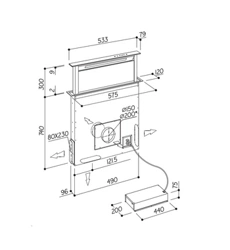
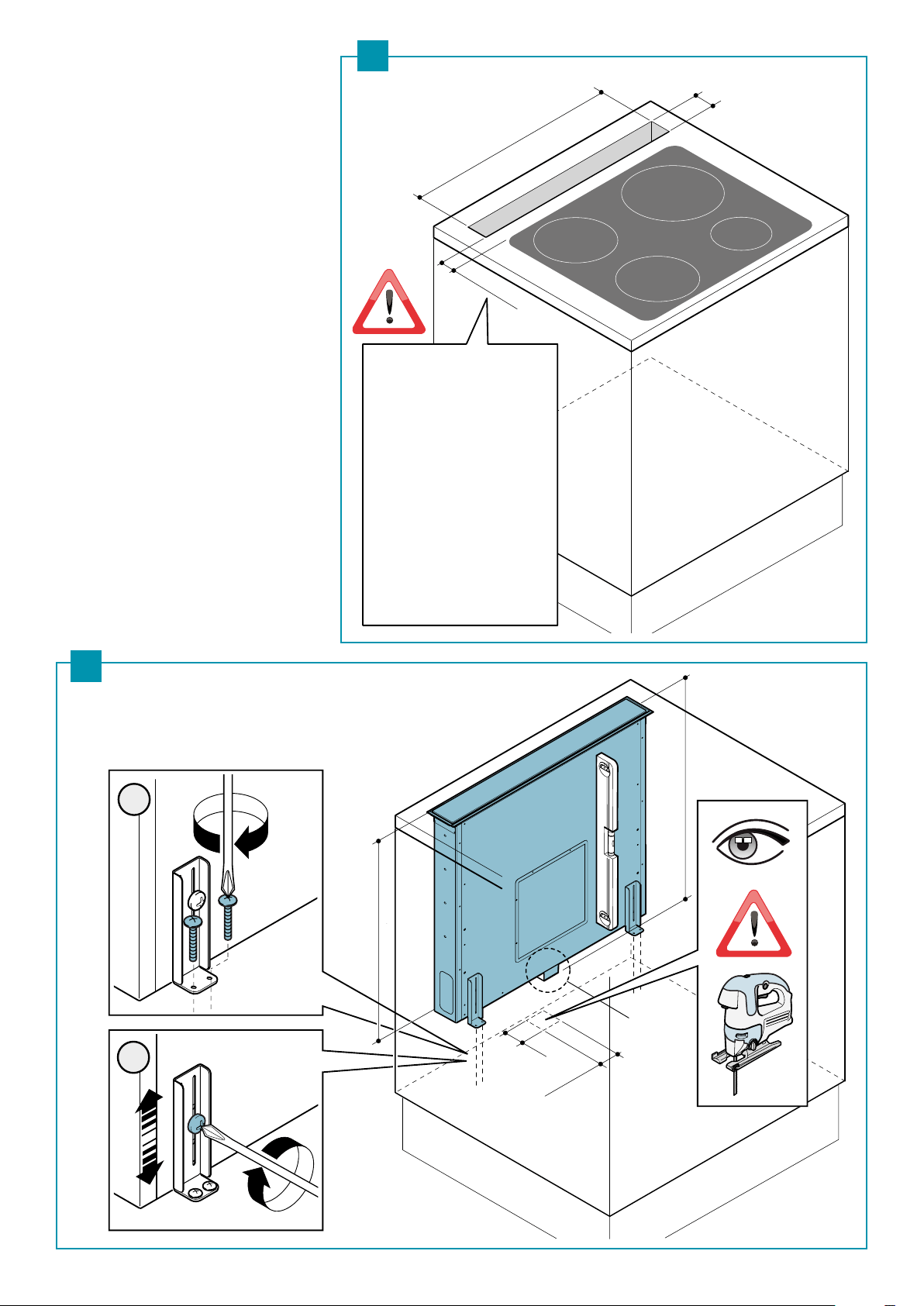
IT - Misure foro per incasso (1),
ssaggio al piano d'appoggio (2)
UK - Recess hole dimensions (1),
xing to the supporting surface (2)
DE -
Abmessungen der Önung für den Einbau
(1), Befestigung auf der Auageäche (2)
FR -
Dimensions du trou pour l'encastrement (1),
xation sur le plan d'appui (2)
ES - Medidas oricio para encajar (1),
jación en el plano de apoyo (2)
RU -
Размеры отверстия для встраивания (1),
крепление к опорной поверхности (2)
PL - Wymiary otworu wpustowego (1),
mocowanie do powierzchni nośnej (2)
NL - Afmetingen inbouwruimte (1),
bevestiging aan steunvlak (2)
PT - Medidas orifício para encaixe (1),
xação ao plano de apoio (2)
DK - Mål indbygget hul (1),
fastgøring til støttepladen (2)
SE - Hålmått för inbyggd montering (1),
fastsättning till stödbänken (2)
FI - Upotusasennusaukon mitat (1),
kiinnitys tukitasoon (2)
NO - Mål innfellingsåpning (1),
feste til støtteplanet (2)
810 mm
1100 mm
98 mm
60 mm
715 mm
motor pin
738 mm max
1
2
70 mm
57 mm
2
1
IT - Misura ideale.
UK - Ideal size.
DE - Ideale Größe.
FR - Mesure idéale.
ES - Medida ideal.
RU - Идеальный размер.
PL - Wymiar precyzyjny.
NL - Ideale afmeting.
PT - Medida ideal.
DK - Ideelt mål.
SE - Idealiskt mått.
FI - Ihanteellinen mitta.
NO - Ideelle mål.
6
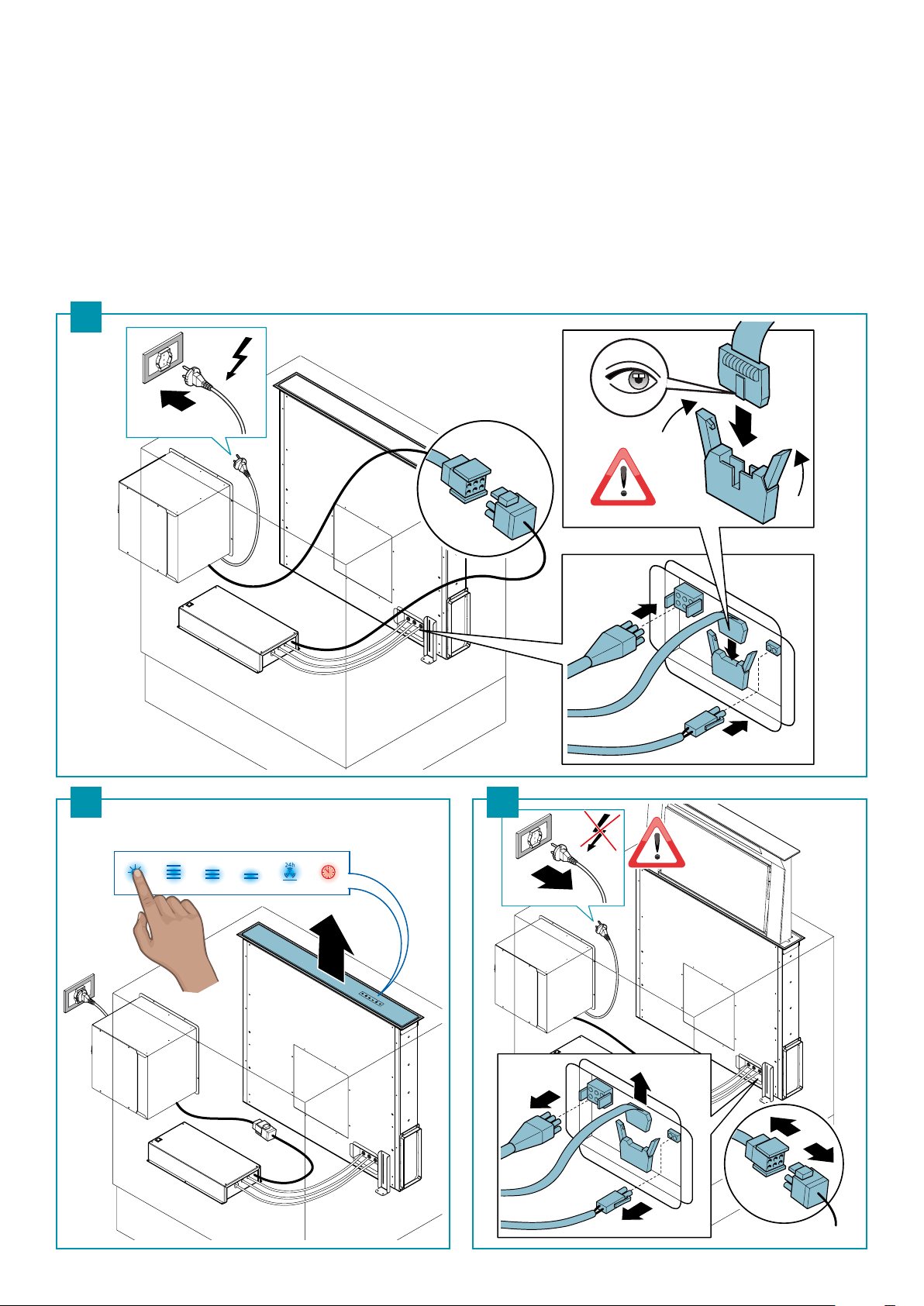
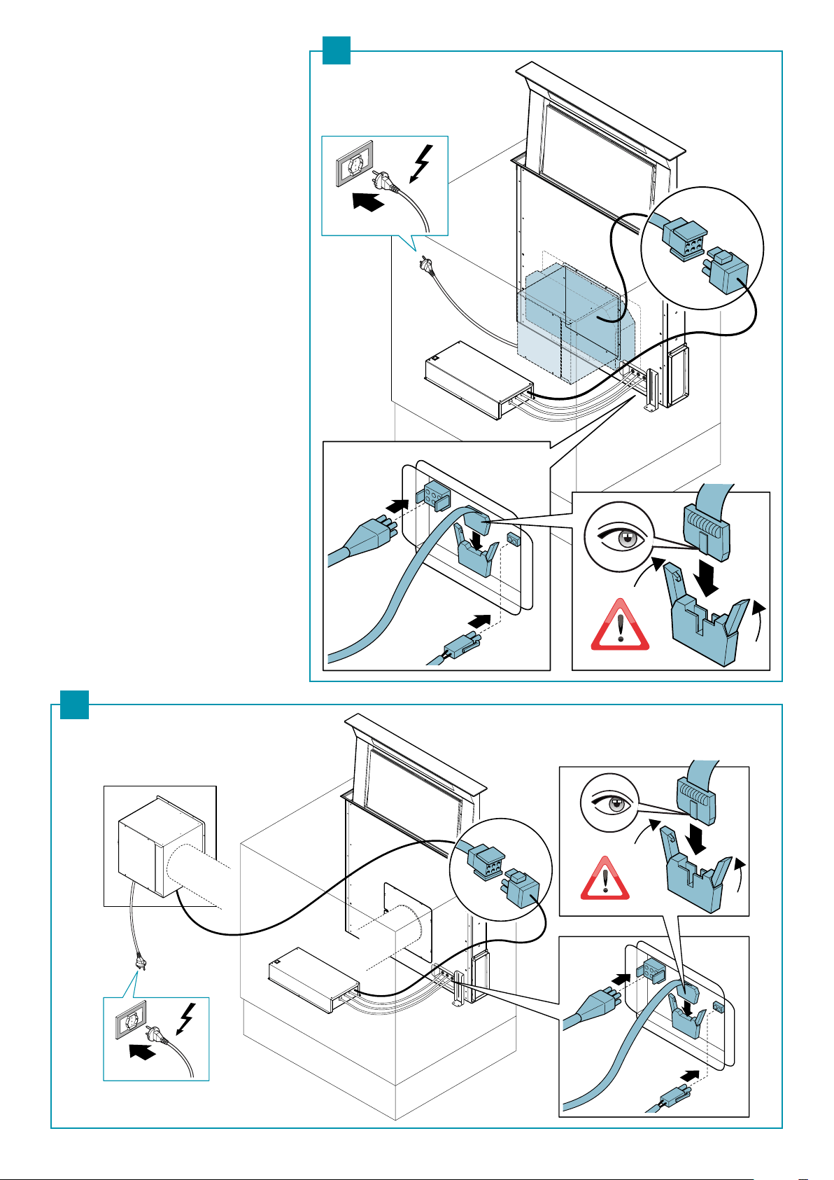
IT - Collegamento elettrico provvisorio (3);
apertura della cappa per installazione (4)(5).
UK - Temporary electrical connection (3);
opening the hood for installation (4)(5).
DE - Provisorischer elektrischer Anschluss (3);
Önen der Haube zur Installation (4)(5).
FR - Branchement électrique provisoire (3);
ouverture de la hotte pour l'installation (4) (5).
ES - Conexión eléctrica provisional (3);
apertura de la campana para la instalación (4)(5).
RU - Временное электрическое подключение (3);
открытие вытяжки для установки (4)(5).
PL - Prowizoryczne połączenie elektryczne (3);
otwór okapu w celu instalacji (4)(5).
230V
3
seconds
230V
3
4 5
NL - Tijdelijke elektrische aansluiting (3);
opening van de kap voor de installatie (4)(5).
PT - Ligação elétrica provisória (3);
abertura da capa para instalação (4)(5).
DK - Midlertidig elektrisk tilslutning (3);
åbning af kappen til installation (4)(5).
SE - Tillfällig elanslutning (3);
öppning av äkt för installation (4)(5).
FI - Väliaikainen sähkökytkentä (3);
liesituulettimen aukko asennusta varten (4)(5).
NO - Provisorisk elektrisk tilkobling (3);
åpning av ventilatorhetten for installasjon (4)(5).
7
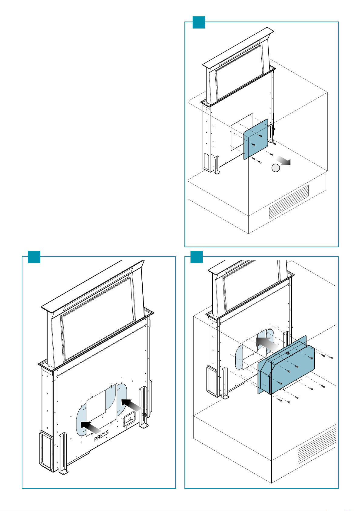
IT - Congurazione con motore frontale:
Togliere il coperchio di chiusura (6); togliere le parti metalliche latera-
li (7); ssare il motore KACL784 (8).
UK - Conguration with front motor:
Remove the cover (6); remove the metal side panels (7); x motor
KACL784 (8).
DE - Konguration mit getrennt montiertem Motor:
Die Abdeckung (6) entfernen; die seitlichen Metallteile (7) entneh-
men; den Motor KACL784 (8) anbringen.
FR - Conguration avec moteur frontal :
Retirer le couvercle de fermeture (6) ; retirer les parties métalliques
latérales (7) ; xer le moteur KACL784 (8).
ES - Conguración con motor parte frontal:
Retire la tapa del cierre (6); Retire las partes metálicas laterales (7);
jar el motor KACL784 (8).
RU - Конфигурация с передним двигателем:
Снять закрывающую крышку (6); снять боковые металлические
детали (7); прикрепить двигатель KACL784 (8).
PL - Konguracja z silnikiem przednim:
Zdjąć obudowę (6), zdjąć metalowe elementy boczne (7), zamocować
silnik KACL784 (8).
NL - Conguratie met motor vooraan:
Verwijder de afdekplaat (6); verwijder de metalen elementen aan de
zijkant (7); bevestig de motor KACL784 (8).
PT - Conguração com motor frontal:
Retirar a tampa de fecho (6); retirar as partes metálicas laterais (7);
xar o motor KACL784 (8).
DK - Konguration med frontal motor:
Fjern lukkedækslet (6); ern de laterale metaldele (7); fastgør moto-
ren KACL784 (8).
SE - Utförande med främre motor:
Avlägsna locket (6); avlägsna metalldelarna på sidan (7); fäst motorn
KACL784 (8).
FI - Kongurointi edessä olevalla moottorilla:
Irrota sulkukansi (6); ota pois metalliset sivuosat (7); kiinnitä moottori
KACL784 (8).
NO - Kongurering med framre motor:
Fjern lukkedeksel (6), ern metalldelene på siden (7), fest motoren
KACL784 (8).
KACL.784
1
7 8
6
8
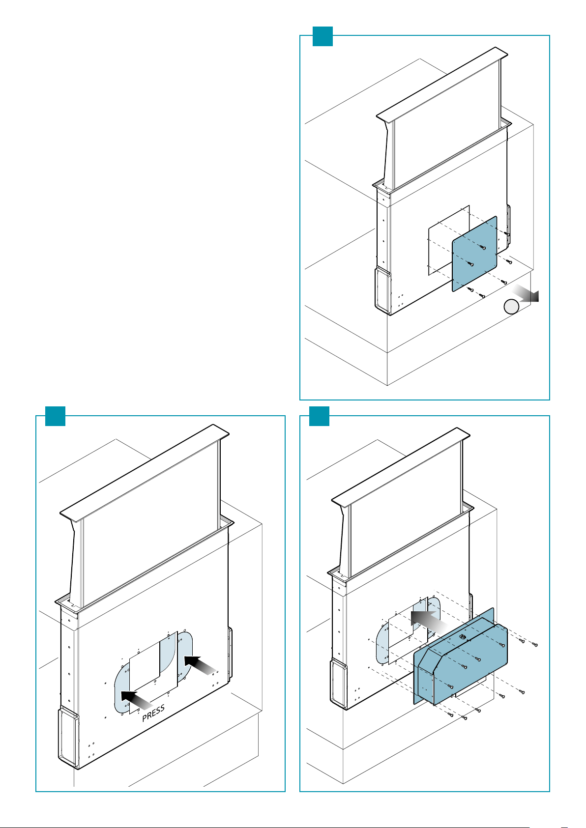
IT - Congurazione con motore posteriore:
Togliere il coperchio di chiusura (9); togliere le parti metalliche latera-
li (10); ssare il motore KACL784 (11).
UK - Conguration with back motor:
Remove the cover (9); remove the metal side panels (10); x motor
KACL784 (11).
DE - Konguration mit rückseitigem Motor:
Die Abdeckung (9) entfernen; die seitlichen Metallteile (10) entneh-
men; den Motor KACL784 (11) anbringen.
FR - Conguration avec moteur à l'arrière :
Retirer le couvercle de fermeture (9) ; retirer les parties métalliques
latérales (10) ; xer le moteur KACL784 (11).
ES - Conguración con motor parte trasera:
Retire la tapa del cierre (9); Retire las partes metálicas laterales (10);
jar el motor KACL784 (11).
RU - Конфигурация с задним двигателем:
Снять закрывающую крышку (9); снять боковые металлические
детали (10); прикрепить двигатель KACL784 (11).
PL - Konguracja z silnikiem tylnym:
Zdjąć obudowę (9), zdjąć metalowe elementy boczne (10), zamo-
cować silnik KACL784 (11).
NL - Conguratie met motor achteraan:
Verwijder de afdekplaat (9); verwijder de metalen elementen aan de
zijkant (10); bevestig de motor KACL784 (11).
PT - Conguração com motor posterior:
Retirar a tampa de fecho (9); retirar as partes metálicas laterais (10);
xar o motor KACL784 (11).
DK - Konguration med bagmotor:
Fjern lukkedækslet (9); ern de laterale metaldele (10); fastgør moto-
ren KACL784 (11).
SE - Utförande med bakre motor:
Avlägsna locket (9); avlägsna metalldelarna på sidan (10); fäst motorn
KACL784 (11).
FI - Kongurointi takana olevalla moottorilla:
Irrota sulkukansi (9); ota pois metalliset sivuosat (10); kiinnitä moot-
tori KACL784 (11).
NO - Kongurering med bakre motor:
Fjern lukkedeksel (9), ern metalldelene på siden (10), fest motoren
KACL784 (11).
KACL.784
1
10 11
9
ITALIANO
9
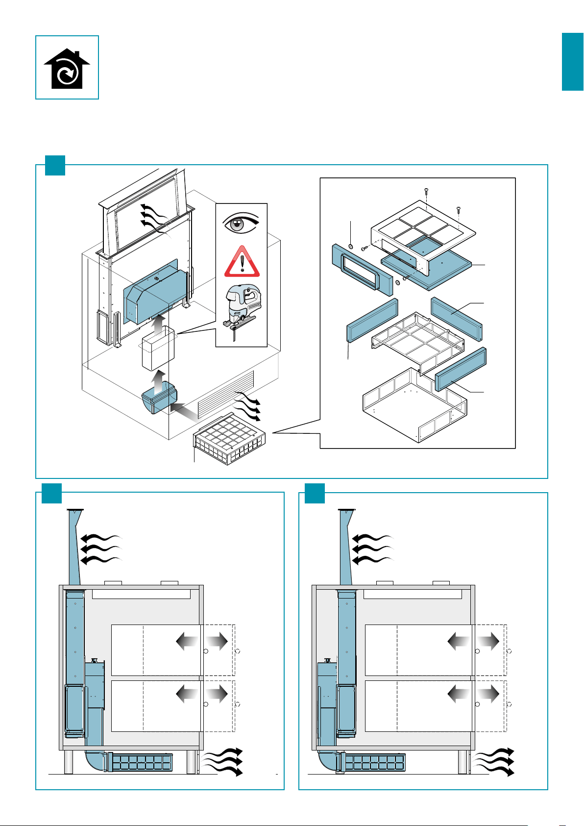
IT - Installazione ltro carbone-zeolite (opzionale) (12).
Motore frontale (13) motore posteriore (14).
UK - Installing the carbon-zeolite lter (optional) (12).
Front motor (13) back motor (14).
DE - Installation des Kohlensto-Zeolith-Filter (Option) (12).
Frontmotor (13) rückseitiger Motor (14).
FR - Installation du ltre charbon-zéolite (en option) (12).
Moteur frontal (13) moteur à l'arrière (14).
ES - Instalación de ltro de carbón-zeolita (opcional) (12).
Motor parte frontal (13) motor parte trasera (14).
RU - Установка угольного цеолитного фильтра
(дополнительного) (12).
Передний двигатель (13) задний двигатель (14).
AIR
AIR
AIR
AIR
KACL.930
TYPE B
TYPE A
MAGNET
TYPE A
TYPE A
12
13 14
PL - Instalacja ltra węglowo-zeolitowego (opcjonalna) (12).
Silnik przedni (13) silnik tylny (14).
NL - Installatie zeoliet-/koolstolter (optie) (12).
Motor vooraan (13) motor achteraan (14).
PT - Instalação ltro carvão-zeólito (opcional) (12).
Motor frontal (13) motor posterior (14).
DK - Installation af zeolit-kullteret (valgfrit) (12).
Frontal motor (13) bagmotor (14).
SE - Installation kol-zeolitlter (tillval) (12).
Främre motor (13) bakre motor (14).
FI - Hiili-zeoliittisuodattimen asennus (lisävaruste) (12).
Edessä oleva moottori (13) takana oleva moottori (14).
NO - Installasjon av karbon-zeolitt-lter (ekstrautstyr) (12).
Framre motor (13), bakre motor (14).
10
INLET
KACL.798
15
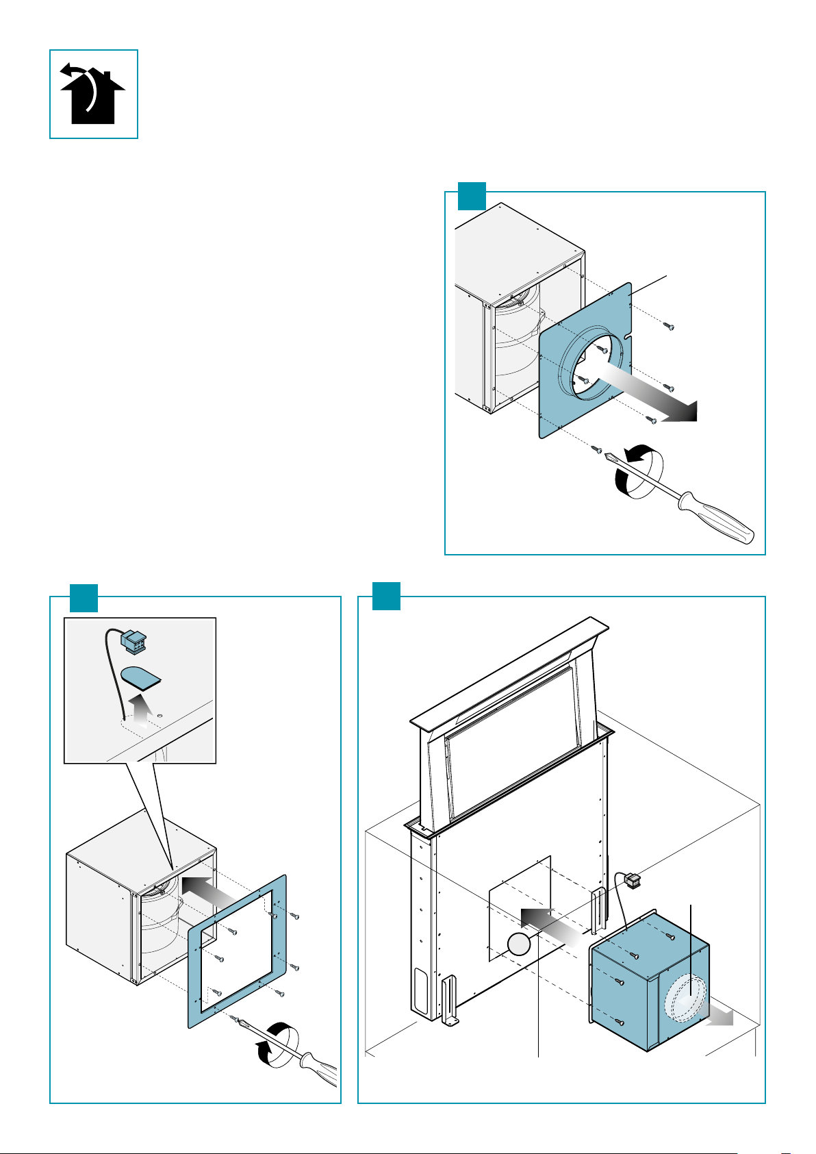
IT - Sostituire "inlet" originale (15), con staa di ssaggio motore sulla cappa (16); ssare il motore alla cappa se l'uscita aria
è frontale (17). Vedere (18) - (19) per altre direzioni.
UK - Replace the original “inlet” (15) with the bracket xing the motor to the hood (16); secure the motor to the hood if the air
exhaust is on the front (17). For other directions see (18) (19).
DE - Das Original-"Inlet" (15) mit Motorbefestigungsbügel auf der Haube (16) ersetzen; den Motor an der Haube befestigen,
wenn der Luftauslass frontal erfolgt (17). Siehe (18) (19) wegen anderen Richtungen.
FR - Remplacer "inlet" original (15), avec l'étrier de xation du moteur sur la hotte (16) ; xer le moteur à la hotte si la sortie
d'air est frontale (17). Voir (18) (19) pour d'autres directions.
6
OUTLET
16
17
ES - Reemplazar "inlet" original (15), con abrazadera de jación motor en la cam-
pana (16); jar el motor en la campana si la salida del aire es frontal (17).
Véase (18) (19) para otras direcciones.
RU - Заменить изначальный "вход" (15) на кронштейн для крепления
двигателя на вытяжке (16); прикрепить двигатель к вытяжке при
переднем выходе воздуха (17). При других направлениях см. (18) (19).
PL - Zastąpić oryginalny „wpust“ (15) uchwytem mocującym silnik na okapie
(16), zamocować silnik na okapie, jeśli wylot powietrza znajduje się w części
przedniej (17). Patrz (18) (19) w celu uzyskania dalszych instrukcji.
NL - De originele “ingang” (15) vervangen voor de bevestigingsbeugel van de
motor boven de kap (16); de motor bevestigen aan de kap als de luchtuittre-
de aan de voorkant is geplaatst (17). Zie (18) (19) voor andere richtingen.
PT - Substituir "inlet" original (15), com xador motor na capa (16); xar o motor
à capa se a saída de ar é frontal (17). Consultar (18) (19) para outras direções.
DK - Udskift det originale "inlet" (15), med beslag til fastgøring af mortoren på
kappen (16); fastgør motoren til kappen hvis luftudgangen er frontal (17).
Se (18) (19) for andre direktioner.
SE - Byt det originala "inloppet" (15) mot fästbleck för motor på äkten (16); fäst
motorn till äkten vid främre luftöppning (17). Se (18) (19) för ytterligare
instruktioner.
FI - Vaihda alkuperäinen "inlet" (15) liesituulettimessa olevaan moottorin kiin-
nityskannattimeen (16); kiinnitä moottori liesituulettimeen jos ilman ulo-
stulo on edessä (17). Katso (18) (19) muita suuntia varten.
NO - Skift ut originalt "inlet" (15) med festestang for motor på ventilatorhette
(16), fest motoren til ventilatorhetten hvis luftutgangen er frontal (17).
Se (18) (19) for andre retninger.
ITALIANO
11
360°
AIR
19
x 8
4
2
1
180°
3
90°
5
x 8
6
OUTLET
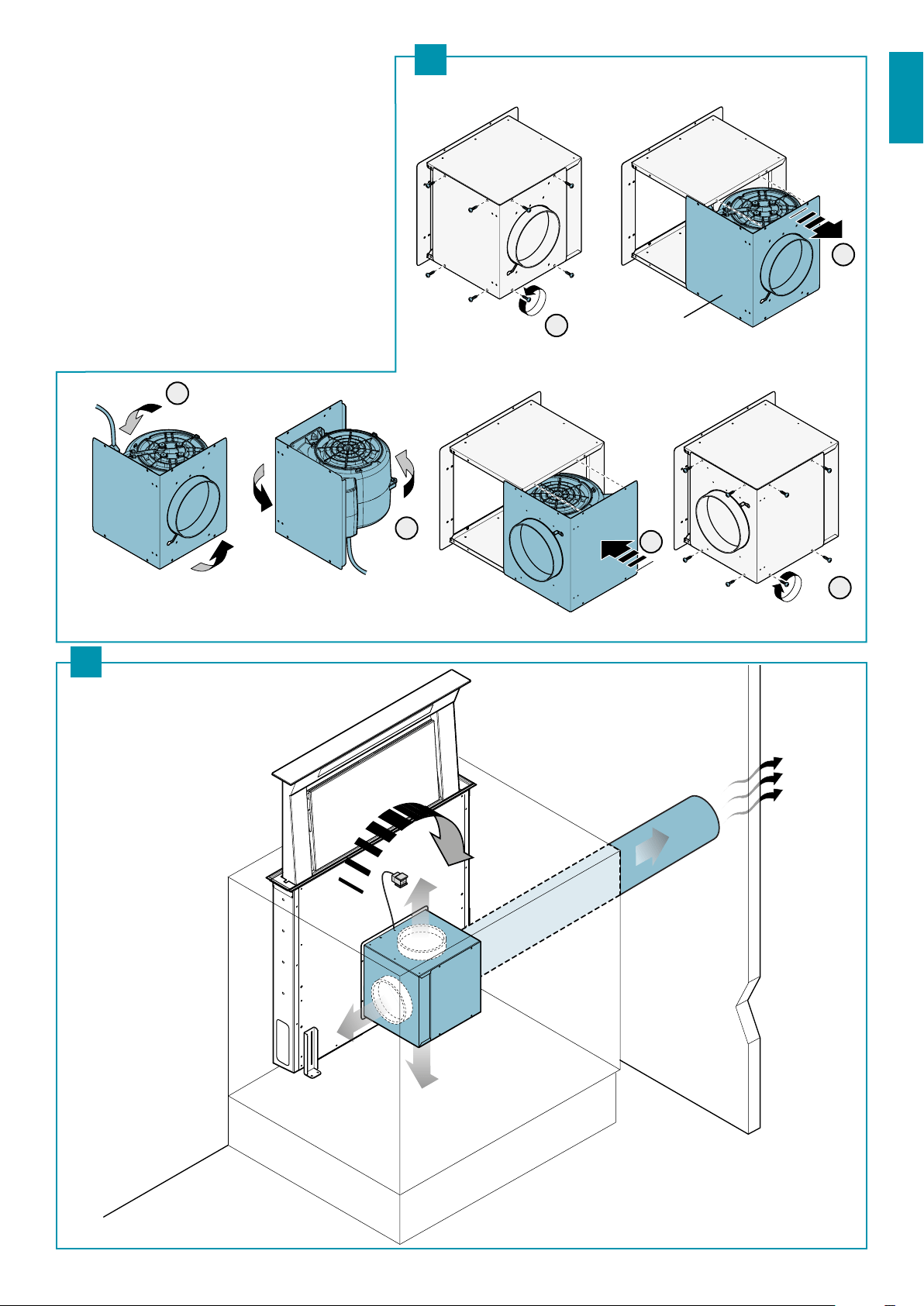
IT - KACL.798 Spostamento laterale dell'uscita aria
UK - KACL.798 Side movement of the air exhaust
DE -
KACL.798 Seitliche Verschiebung des Luftauslasses
FR - KACL.798 Déplacement latéral de la sortie d'air
ES -
KACL.798 Desplazamiento lateral de la salida del aire
RU - KACL.798 Боковое смещение выхода воздуха
PL - KACL.798 Przesunięcie boczne wylotu powietrza
NL -
KACL.798 Zijlingse verplaatsing van de luchtuittrede
PT - KACL.798 Deslocamento lateral da saída de ar
DK - KACL.798 Bevægelse til siden af luftudgangen
SE - KACL.798 Sidoföryttning av luftöppningen
FI - KACL.798 Ilman ulostulon siirto sivulle
NO - KACL.798 Flytting av luftutgangen til siden.
18
12
360°
AIR
6
OUTLET
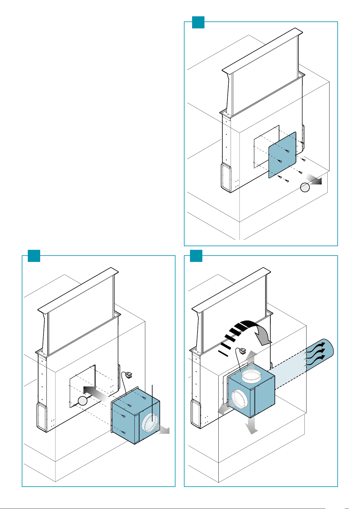
IT - Congurazione con motore posteriore
UK - Conguration with back motor
DE - Konguration mit rückseitigem Motor
FR - Conguration avec moteur à l'arrière
ES - Conguración con motor parte trasera
RU - Конфигурация с задним двигателем
PL - Konguracja z silnikiem tylnym
NL - Conguratie met motor achteraan
PT - Conguração com motor posterior
DK - Konguration med bagmotor
SE - Utförande med bakre motor
FI - Kongurointi takana olevalla moottorilla
NO - Kongurering med bakre motor
KACL.798
1
21 22
20
ITALIANO
13
IT - Congurazione con motore remoto:
Tubi rettangolari (23); tubi tondi (24).
UK - Conguration with remote motor:
Rectangular pipes (23); round pipes (24).
DE -
Konguration mit getrennt montiertem Motor:
Rechteckige Röhren (23); runde Röhren (24).
FR -
Conguration avec moteur monté séparément :
Tuyaux rectangulaires (23) ; tuyaux ronds (24).
ES - Conguración con motor externo:
Tubos rectangulares (23); tubos redondos (24).
RU -
Конфигурация с удаленным двигателем:
Прямоугольные трубы (23); круглые трубы (24).
PL - Konguracja z silnikiem zewnętrznym:
Przewody prostokątne (23), przewody okrągłe (24).
NL - Conguratie met motor op afstand:
Rechthoekige leidingen (23); ronde leidingen (24).
PT - Conguração com motor remoto:
Tubos retangulares (23); tubos redondos (24).
90
220
Motor
Motor
23
24
DK -
Konguration med motor monteret separat
Rektangulære rør (23); runde rør (24).
SE - Utförande med separat monterad motor:
Rektangulära rör (23); runda rör (24).
FI - Kongurointi etäkäyttömoottorilla:
Suorakulmaiset putket (23); pyöreät
putket (24).
NO - Kongurering med ernmotor:
Rektangulære rør (23), runde rør (24).
ONLY
FALMEC
MOTORS!
ONLY
FALMEC
MOTORS!
14
25IT - Collegamento elettrico:
motore a bordo (25); motore remoto (26).
UK - Electrical connection:
onboard motor (25); remote motor (26).
DE - Elektrischer Anschluss:
Eingebauter Motor (25); getrennt montierter
Motor (26).
FR - Branchement électrique :
moteur à bord (25) ; moteur monté séparément
(26);
ES - Conexión eléctrica:
motor a bordo (25); motor externo (26).
RU - Подключение к электросети:
двигатель на машине (25); удаленный
двигатель (26).
PL - Połączenie elektryczne:
silnik wbudowany (25), silnik zewnętrzny (26).
NL - Elektrische aansluiting:
motor in machine (25); motor op afstand (26).
PT - Ligação elétrica:
motor a bordo (25); motor remoto (26).
DK - Elektrisk tilslutning:
Motor ombord (25); motor monteret separat
(26).
SE - Elanslutning:
monterad motor (25); separat monterad motor
(26).
FI - Sähkökytkentä:
moottori asennettuna (25); etäkäyttömoottori
(26).
NO - Elektrisk tilkobling:
motor ombord (25), ernmotor (26).
26
ITALIANO
15
Magnets
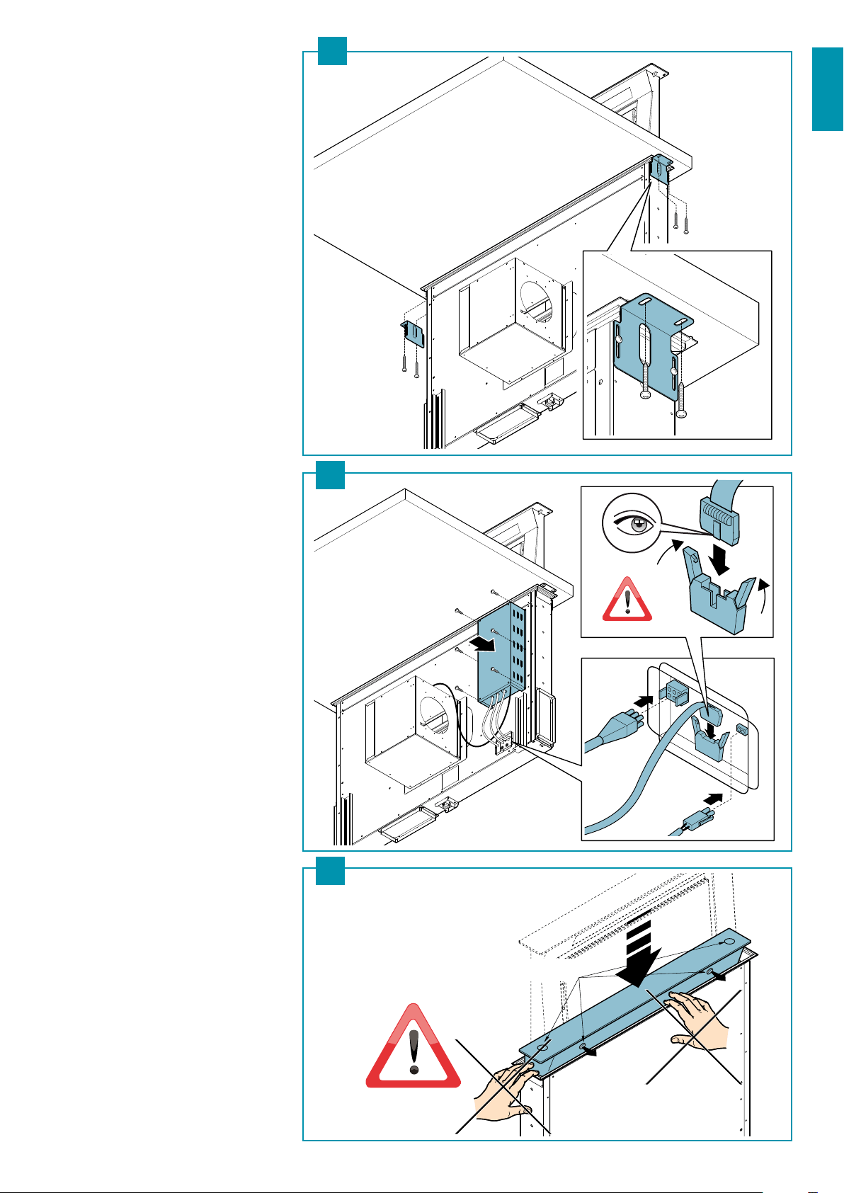
IT - Stae di ssaggio al TOP (27).
Fissaggio unita di controllo alla cappa (28).
Avvertenza anti schiacciamento mani (29).
UK - Brackets xing to the TOP (27).
Fixing the control unit to the hood (28).
Hand anti-crushing warning (29).
DE - Befestigungsbügel am TOP (27).
Befestigung des Steuergeräts an der Haube (28).
Warnhinweis zum Schutz gegen das Eink-
lemmen der Hände (29).
FR - Étriers de xation au TOP (27).
Fixation unité de contrôle à la hotte (28).
Avertissement anti-écrasement des mains (29).
ES - Abrazaderas de jación a la SUPERFICIE DE
APOYO (27).
Fijación unidad de control a la campana (28).
Advertencia contra aplastamiento manos (29).
RU - Кронштейны для крепления к ВЕРХУ (27).
Крепление блока управления к вытяжке
(28).
Предупреждения против сдавливания
рук (29).
PL - Uchwyty mocujące na szczycie (27).
Mocowanie jednostki sterowania do okapu
(28).
Ostrzeżenie przeciw przygnieceniu dłoni (29).
NL - Bevestigingsbeugels aan TOP (27).
Bevestiging controller aan kap (28).
Waarschuwing pletgevaar handen (29).
PT - Fixador no TOP (27).
Fixação unidade de controlo da capa (28).
Advertência anti-esmagamento mãos (29).
DK - Beslag ti fastgøring på TOP (27).
Fastgøring af kontrolenhed til kappen (28).
Advarsel mod klemning af hænder (29).
SE - Fästbleck för TOP (27).
Fastsättning av styrenheten till äkt (28).
Varning klämskydd för händer (29).
FI - TOP-kiinnityskannattimet (27).
Ohjausyksikön kiinnitys liesituulettimeen
(28).
Varoitus käsien litistymisvaara (29).
NO - Festestenger til TOP (27).
Feste av kontrollenheten til ventilatorhetten
(28).
Advarsel om fare for klemming av hender
(29).
29
28
27
21
ENGLISH
SAFETY INSTRUCTIONS
AND WARNINGS
Installation operations are to be carried out by skilled and qualied in-
stallers in accordance with the instructions in this booklet and in compli-
ance with the regulations in force.
DO NOT use the hood if the power supply cable or other components are damaged:
disconnect the hood from the electrical power supply and contact the Dealer or an author-
ised Servicing Dealer for repairs.
Do not modify the electrical, mechanical or functional structure of the equipment.
Do not personally try to carry out repairs or replacements. Interventions carried out
by incompetent and unauthorised persons can cause serious damage to the unit or
physical and personal harm, not covered by the Manufacturer's warranty.
WARNINGS FOR THE INSTALLER
TECHNICAL SAFETY
Before installing the hood, check the integrity and function of each part.
Should anomalies be noted, do not proceed with installation and contact
the Dealer.
Do NOT install the hood if an aesthetic (or cosmetic) defect has been detected. Put it
back into its original package and contact the dealer.
No claim can be made for aesthetic (or cosmetic) defects once it has been installed.
During installation, always use personal protective equipment (e.g.: Safety shoes) and adopt
prudent and proper conduct.
The installation kit (screws and plugs) supplied with the hood is only to be used on masonry
walls: in case of installation on walls of a dierent material, assess other installation options
keeping in mind the type of wall surface and the weight of the hood (indicated on page 2).
Keep in mind that installations with dierent types of fastening systems from those sup-
plied, or which are not compliant, can cause electrical and mechanical seal danger.
Do not install the hood outdoors and do not expose it to atmospheric elements (rain, wind,
etc.).
ELECTRICAL SAFETY
The electrical system to which the hood is to be connected must be in ac-
cordance with local standards and supplied with earthed connection in
compliance with safety regulations in the country of use. It must also com-
ply with European standards regarding radio antistatic properties.
Before installing the hood, check that the electrical mains power supply corresponds with
what is reported on the identication plate located inside the hood.
The socket used to connect the installed equipment to the electrical power supply must
be within reach: otherwise, install a mains switch to disconnect the hood when required.
Any changes to the electrical system must be carried out by a qualied electrician.
The maximum length of the ue fastening screws (supplied by the manufacturer) must be
13 mm. Use of non-compliant screws with these instructions can lead to danger of an elec-
trical nature.
Do not try to solve the problem yourself in the event of equipment malfunction, but contact
the Dealer or an authorised Servicing Department for repairs.
When installing the hood, disconnect the equipment by removing the
plug or switching o the main switch.
FUMES DISCHARGE SAFETY
Do no connect the equipment to discharge pipes of fumes produced from
combustion (for example boilers, replaces, etc.).
Before installing the hood, ensure that all standards in force regarding discharge of air out of
the room have been complied with.
USER WARNINGS
These warnings have been drawn up for your personal safety and those of
others. You are therefore kindly asked to read the booklet carefully in its
entirety before using the or cleaning the equipment.
The Manufacturer declines all responsibility for any damage caused directly, or in-
directly, to persons, things and pets as a consequence of failing to comply with the
safety warnings indicated in this booklet.
It is imperative that this instructions booklet is kept together with the equipment for
any future consultation.
If the equipment is sold or transferred to another person, make sure that the booklet is
also supplied so that the new user can be made aware of the hood's operation and relative
warnings.
After the stainless steel hood has been installed, it will need to be cleaned to remove any
residues remaining from the protection adhesive as well as any grease and oil stains which, if
not removed, can cause irreversible damage to the hood surface. To properly clean the unit,
the manufacturer recommends using the supplied moist wipes, which are also available
sold separately.
Insist on original spare parts.
INTENDED USE
The equipment is solely intended to be used to extract fumes generated from cook-
ing food in non-professional domestic kitchens: any other use is improper. Improper
use can cause damage to persons, things, pets and exempts the Manufacturer from
any liability.
The equipment can be used by children over the age of 8 and by persons with reduced
physical, sensory and mental abilities, or with no experience or knowledge, as long as they
do so under supervision or after having received relative instructions regarding safe use of
the equipment and understanding of the dangers connected to it.
Children are not to play with the equipment. Cleaning and maintenance by the user must
not be carried out by children without supervision.
USE AND CLEANING WARNINGS
Before cleaning or carrying out maintenance operations, disconnect the
equipment by removing the plug or switching o the main switch.
Do not use the hood with wet hands or bare feet.
Always check that all electrical parts (lights, extractor fan) are o when the equipment is
not being used.
The maximum overall weight of any objects placed or hung (if applicable) on the hood must
not exceed 1.5 Kg.
Always supervise the cooking process during the use of deep-fryers: Overheated oil can
catch re.
Do not leave open, unattended ames under the hood.
Do not prepare food over an open ame under the hood.
Never use the hood without the metal anti-grease lters: in this case, grease and dirt will
deposit in the equipment and compromise its operation.
Accessible parts of the hood can be hot when used at the same time as the cooking ap-
pliances.
Do not carry out any cleaning operations when parts of the hood are still hot.
There can be a risk of re if cleaning is not carried out according to the instructions and
products indicated in this booklet.
Disconnect the main switch when the equipment is not used for long periods of time.
If other appliances that use gas or other fuels are being used at the same
time (boiler, stove, replaces, etc.), make sure the room where the fumes
are discharged is well-ventilated, in compliance with the local regulations.
INSTALLATION
only intended for qualied personnel
Before installing the hood, carefully read the chapter 'SAFETY IN-
STRUCTIONS AND WARNINGS'.
TECHNICAL FEATURES
The technical specications are exhibited on the labels located inside the hood.
POSITIONING
The minimum distance between the highest part of the cooking equipment and the
lowest part of the hood is indicated in the installation instructions.
Generally, when the hood is placed over gas cookers, the distance must be at least 65 cm
(25.6''). However, according to an interpretation of standard EN60335-2-31 dated 11-07-
2002 of TC61 (sub-clause 7.12.1 meeting 15 agenda item 10.11), the minimum distance
between the cooker and lower part of the hood can be reduced to the quota reported in
the installation instructions.
Should the instructions for the gas cooker specify a greater distance, this must be taken
into consideration.
Do not install the hood outdoors and do not expose it to outdoor environment (rain, wind,
etc.).
22
ELECTRICAL CONNECTION
(only intended for qualied personnel)
Disconnect the equipment from electrical mains power supply before carry-
ing out any operations on the hood.
Ensure that the wires inside the hood are not disconnected or cut:
in the event of damage, contact your nearest Servicing Department.
Refer to qualied personnel for electrical connections.
Connection must be carried out in compliance with the provisions of law in force.
Before connecting the hood to the electrical mains power supply, check that:
rWPMUBHFTVQQMZDPSSFTQPOETXJUIXIBUJTSFQPSUFEPOUIFEBUBQMBUFMPDBUFEJOTJEFUIF
hood;
rUIFFMFDUSJDBMTZTUFNJTDPNQMJBOUBOEDBOXJUITUBOEUIFMPBETFFUIFUFDIOJDBMTQFDJñ-
cations located inside the hood);
rUIFQPXFSTVQQMZQMVHBOEDBCMFEPOPUDPNFJOUPDPOUBDUXJUIUFNQFSBUVSFTFYDFFE-
ing 70 °C;
rUIFQPXFSTVQQMZTZTUFNJTFíFDUJWFMZBOEQSPQFSMZDPOOFDUFEUPFBSUIJODPNQMJBODF
with regulations in force;
r
the socket used to connect the hood is within reach.
In case of:
rEFWJDFTñUUFEXJUIDBCMFTXJUIPVUBQMVHUIFUZQFPGQMVHUPVTFJTBhhTUBOEBSEJTFEhhPOF
The wires must be connected as follows: yellow-green for earthing, blue for neutral and
brown for the phase. The plug must be connected to an adequate safety socket.
r
xed equipment not provided with a power supply cable and plug, or any other device
that ensures disconnection from the electrical mains, with an opening gap of the con-
tacts that enables total disconnection in overvoltage category III conditions.
Said disconnection devices must be provided in the mains power supply in compliance
with installation regulations.
The yellow/green earth cable must not be cut o by the switch.
The Manufacturer declines all responsibility for failure to comply with the safety regulations.
FUMES DISCHARGE
EXTERNAL EXHAUST HOOD (SUCTION)
In this version the fumes and vapours are discharged outside through
the exhaust pipe.
To this end, the hood outlet tting must be connected via a pipe, to an
external output.
The outlet pipe must have:
rBEJBNFUFSOPUMFTTUIBOUIBUPGUIFIPPEñUUJOH
rBTMJHIUTMPQFEPXOXBSETESPQJOUIFIPSJ[POUBMTFDUJPOTUPQSFWFOUDPOEFOTBUJPOGSPN
owing back into the motor.
rUIFNJOJNVNSFRVJSFEOVNCFSPGCFOET
rUIFNJOJNVNSFRVJSFEMFOHUIUPBWPJEWJCSBUJPOTBOESFEVDFUIFTVDUJPOQFSGPSNBODFPG
the hood.
You are required to insulate the pipes if it passes through cold environments.
In the presence of motors with 800m
3
/h or higher, a check valve is present to prevent
external air owing back.
Deviation for Germany:
when the kitchen hood is used at the same time as appliances that are powered by energy other
than electricity, the negative pressure in the room must not exceed 4 Pa (4 x 10⁻⁵ bar).
HOOD WITH INTERNAL RECIRCULATION (FILTERING)
In this model, the air passes through the charcoal lters to be puried
and recycled in the environment.
Ensure that the active carbon lters are assembled into the hood, if not,
install them as indicated in the assembly instructions.
In this version the check valve must not be assembled: remove it if it is on the air
outlet tting of the motor.
ASSEMBLY INSTRUCTIONS
only intended for qualied personnel
The hood can be installed in various congurations.
The generic assembly steps apply to all installations; for each case, follow
the specic steps provided for the required installation.
OPERATION
WHEN TO TURN ON THE HOOD?
Switch on the hood at least one minute before starting to cook to direct fumes and vapours
towards the suction surface.
After cooking, leave the hood operating until complete extraction of all vapours and odours.
By means of the Timer function, it is possible to set auto switch-o function which will allow
the hood to turn o automatically after 15 minutes of operation.
WHICH SPEED IS TO BE SELECTED?
1st speed: maintains the circulation of clean air with low electricity consumption.
2nd speed: normal conditions of use.
3rd speed: presence of strong odours and vapours.
4th speed: rapid disposal of odours and vapours.
WHEN SHOULD THE FILTERS BE WASHED OR REPLACED?
The metal lters must be cleaned every 30 hours of operation.
The active carbon lters must be replaced every 3-4 months, depending on the use of the
hood.
For further details see the “MAINTENANCE” chap.
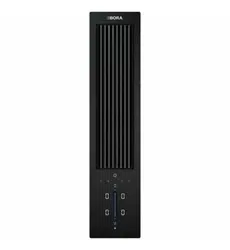
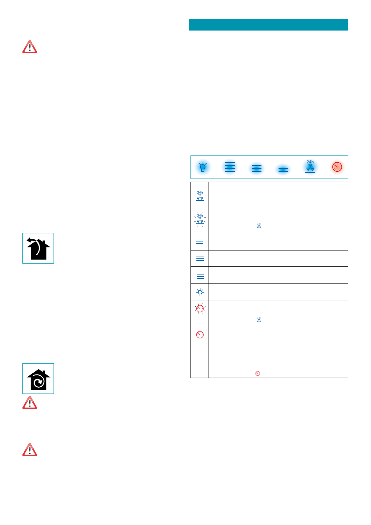
TOUCH PUSHBUTTON PANEL
ON/OFF (Blue led steady on)
Motor on/o and Speed 1
ON/OFF (blue led ashing)
If pressed for more than 3 seconds, it activates the 24h cycle (1h ON -> 3h
OFF -> 1h ON)
the function deactivates if:
- The motor turns o (key
)
- After 24h
Speed 2 activation
Speed 3 activation
Speed 4 activation for a few minutes only
Light on/o
TIMER (Red LED ashing)
Auto switch-o after 15 min.
The function deactivates (red LED o ) if:
- The motor turns o (key
).
- The speed is changed.
With hood open:
FILTER ALARM (red LED steady on)
Anti-grease lter maintenance after approximately 30 hours of operation.
Press the meter for 3 seconds to reset.
With hood closed:
If pressed for over 3 seconds, the hood opens for maintenance.
No control active.
To close the hood, press (
) again for 3 seconds.
23
ENGLISH
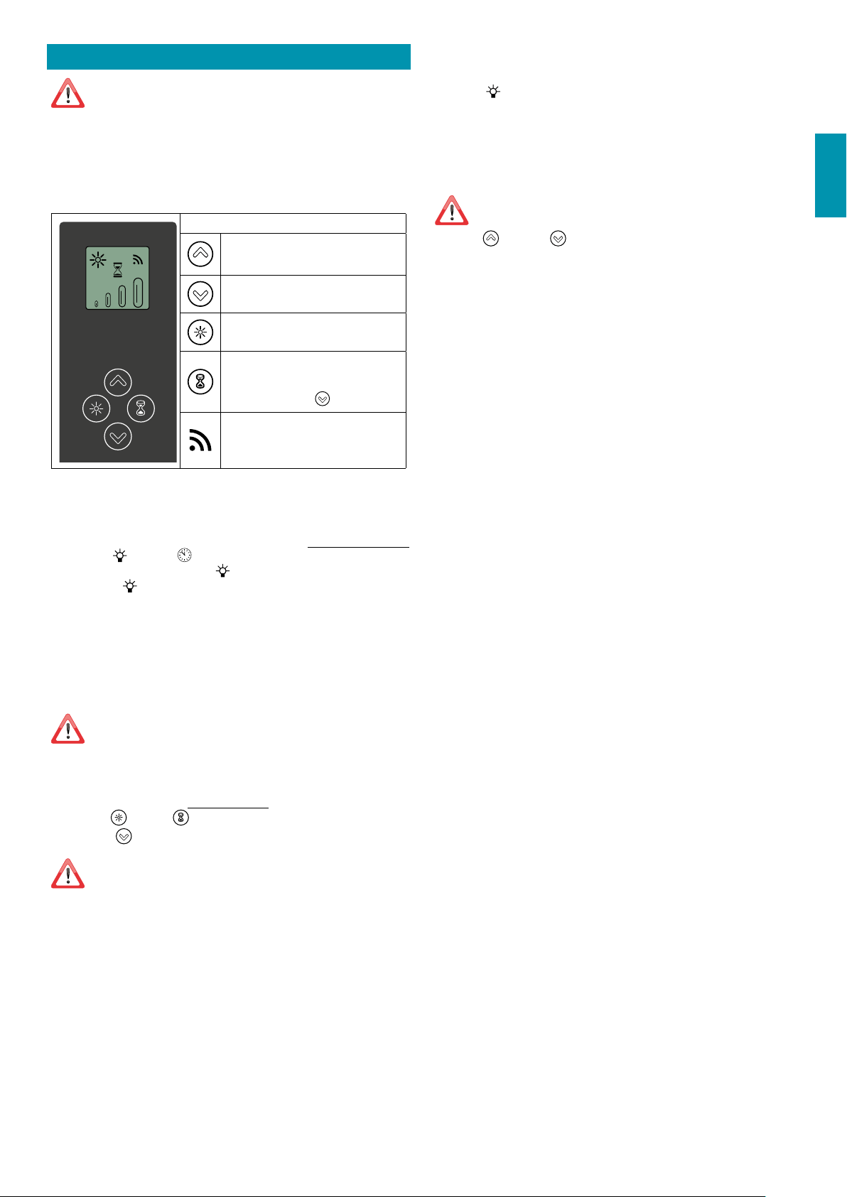
USING THE RADIO CONTROL
WARNINGS!:
Place the hood away from sources of electromagnetic waves (e.g. micro-
wave ovens), which could interfere with the radio control and with the hood
electronics.
The maximum operating distance is 5 metres, that may vary according to the pres-
ence of electromagnetic interferences.
Radio control operated at 433.92MHz.
The radio control consists of two parts:
- the receiver built into the hood;
- the transmitter shown here in the gure.
DESCRIPTION OF TRANSMITTING COMMANDS
UP
Motor switch-on and speed increase from 1
to 4. Speed 4 is only active for a few minutes.
DOWN
Speed decrease and motor switch-o.
Light ON-OFF
TIMER ON: The motor automatically switch-
es o after 15 min.
The function is automatically disabled if the
motor is switched o (
key)
Command transmission active
ACTIVATION PROCEDURE
Before using the radio control, follow the procedure below on the hood pushbutton panel:
t Press LIGHT (
) and TIMER ( ) simultaneously until all LEDs start ashing.
t Release the two keys and press LIGHT (
) again until all LEDs are lit up.
t Release LIGHT (
): now the receiver is active.
This procedure is also used to deactivate the receiver.
RADIO CONTROL CODE CHANGE
With only one radio control, go directly to point 2.
With several radio controls in the same room, a new code can be created by following the
procedure below.
Disconnect the power to the hood before starting the procedure.
1) - CREATE A NEW CODE
The procedure is to be carried out on the radio control.
t Press LIGHT
and TIMER simultaneously until the display starts ashing.
t Press DOWN
on the radio control: saving is conrmed by three brief ashes of the
display. The new code cancels and replaces the previous default code.
Reconnect the hood to the electrical power supply, making sure that the
lights and motor are o.
2) - ASSOCIATING THE RADIO CONTROL WITH THE HOOD
USING THE TOUCH PUSHBUTTON PANEL
press LIGHT (
) on the hood pushbutton panel for 2 seconds:
the red LED lights up.
press any key on the radio control within 10 seconds.
RESTORING DEFAULT CODE
the procedure is to be carried out if the hood is disposed of, sold or transferred.
Disconnect the power to the hood before starting the procedure.
t Press UP
and DOWN simultaneously on the radio control for more than 5 sec-
onds: reset is conrmed by three brief ashes of the display.
t Reconnect the hood to the electrical power supply.
t Proceed with associating the hood and the radio control, as described in point 2.
24
MAINTENANCE
Before cleaning or carrying out maintenance operations, disconnect the
equipment by removing the plug or switching o the main switch.
Do not use detergents containing abrasive, acidic or corrosive substances
or abrasive cloths.
Regular maintenance guarantees proper operation and performance over time.
Special attention is to be paid to the metal anti-grease lters : frequent cleaning of the
lters and their supports ensures that no ammable grease is accumulated.
CLEANING OF EXTERNAL SURFACES
You are advised to clean the external surfaces of the hood at least once every 15 days
to
prevent oily substances and grease from sticking to them. To clean the brushed stainless
steel hood, the Manufacturer recommends using "Magic Steel" wipes.
Alternatively and for all the other types of surfaces, it can be cleaned using a damp cloth,
slightly moistened with mild, liquid detergent or denatured alcohol.
Complete cleaning by rinsing well and drying with soft cloths.
Do not use too much moisture or water around the push button control
panel and lighting devices in order to prevent humidity from reaching
electronic parts.
The glass panels can only be cleaned with specic, non-corrosive or non-abrasive deter-
gents using a soft cloth.
The Manufacturer declines all responsibility for failure to comply with these instructions.
CLEANING OF INTERNAL SURFACES
Do not clean electrical parts, or parts related to the motor inside the hood,
with liquids or solvents.
For the internal metal parts, see the previous paragraph.
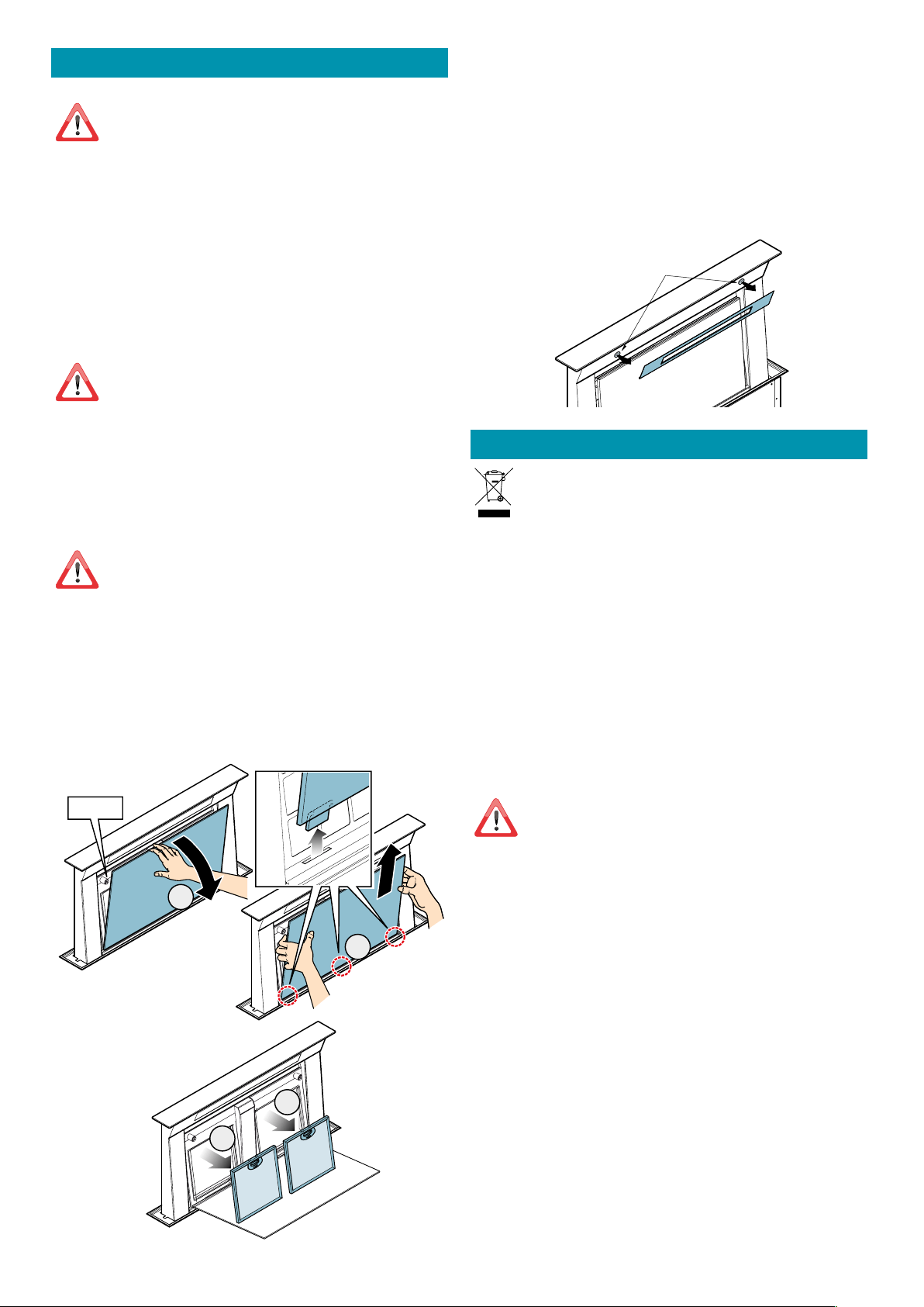
METAL ANTI-GREASE FILTERS
It is advised to frequently wash the metal lters (at least once a month) leaving them to
soak in boiling water and cleaning solution for 1 hour, taking care not to bend them.
Do not use corrosive, acid or alkaline detergents.
Rinse them well and wait for them to be completely dry before reassembling them.
Washing in a dishwasher is permitted, however, it may cause the lter material to darken: to
reduce the possibility of this problem from happening, use low-temperature washes (55°C
max.).
To extract and insert the metal anti-grease lters see the assembly instructions.
1
4
3
MAGNET
2
CARBON-ZEO FILTERS
Under normal conditions, they should be regenerated every 18 months and replaced after
3 years. To regenerate the lter, follow the following procedure:
- Remove the lter as described in the instructions.
- Place the 4 lters (3 x type A and 1 x type B) in a domestic oven at 200°C for about 2 hours.
- When the lter has cooled down, ret the 4 lters onto the metal structure of the KACL.930
lter.
LIGHTING
5IFSBOHFIPPEJTFRVJQQFEXJUIIJHIFîDJFODZMPXDPOTVNQUJPO-&%TQPUMJHIUTXJUIBO
extremely long life-span under normal use conditions.
Should replacement be required, contact a service centre.
Magnets
DISPOSAL AFTER END OF USEFUL LIFE
The crossed-out trash or refuse bin symbol on the appliance means that the
product is WEEE, i.e. “Waste electrical and electronic equipment'', accordingly it
must not be disposed of with regular unsorted waste (i.e. with ''mixed house-
hold waste''), but it must be disposed of separately so that it can undergo specif-
ic processing for its re-use, or a specic treatment, to remove and safely dispose of any
substances that may be harmful to the environment and remove the raw materials that can
be recycled. Proper disposal of these products contributes to saving valuable resources and
avoid potential negative eects on personal health and the environment, which may be
caused by inappropriate disposal of waste.
You are kindly asked to contact your local authorities for further information regarding the
designated waste collection points nearest to you. Penalties for improper disposal of such
waste can be applied in compliance with national regulations.
INFORMATION ON DISPOSAL IN EUROPEAN UNION COUNTRIES
The EU WEEE Directive was implemented dierently in each country, accordingly, if you wish
to dispose of this appliance we suggest contacting your local authorities or dealer to nd
out what the correct method of disposal is.
INFORMATION ON DISPOSAL IN NON-EUROPEAN UNION COUNTRIES
The crossed-out trash or refuse bin symbol is only valid in the European Union: if you wish
to dispose of this appliance in other countries, we suggest contacting your local authorities
or dealer to nd out what the correct method of disposal is.
WARNING!
The Manufacturer reserves the right to make changes to the equipment at any time and
without prior notice. Printing, translation and reproduction, even partial, of this manual are
bound by the Manufacturer's authorisation.
Technical information, graphic representations and specications in this manual are for in-
formation purposes and cannot be divulged.
This manual is written in Italian. The Manufacturer is not responsible for any transcription
or translation errors.

14
WARRANTY
All FALMEC rangehoods come with a 5 year parts and labour warranty. PR Kitchens &
Washrooms will correct, free of charge, any defects in material or workmanship for the
period of 5 years, subject to the terms of our warranty stated below.
This warranty will be void if a Falmec range hood is used for commercial purposes.
Some examples of commercial purposes but not limited to, include restaurants, cafes,
schools and clubs.
Rangehoods in the Falmec range (excluding BBQ models) are designed and
warranted “strictly” for indoor use only (household kitchen).
1. This warranty only applies for products installed by a qualified person and when
provided with a certificate of compliance in accordance with State/Territory laws.
2. This product must be used in accordance with the manufacturer’s instructions. This
warranty does not apply should the defect in or failure of the product be attributable to
misuse, abuse, accident or non-observation of the manufacturer’s instructions on the
part of the user. FALMEC appliances does not accept liability for any direct or
consequential loss, damage or other expense caused by or arising out of any failure to
install or use the product in accordance with the manufacturer’s instructions.
3. The warranty does not cover failures due to normal wear and tear with reasonable
use or consumable components such as globes, filters, etc.
4. PR Kitchens & Washrooms, at its own discretion may replace or repair any defective
component(s) to affect a repair due to any faulty workmanship and material. The
warranty does not cover breakage of outer glass panels attributed to external damage.
5. The warranty provided is a “Repair Warranty” and in an extreme event if a repair
cannot take place, a replacement will be provided of an equivalent current model where
the balance of the warranty period from the original date of purchase will take effect.
6. This warranty is immediately void if the serial or model number label is removed,
defaced, serviced or repaired by a unauthorised/unqualified personal or used for
industrial/commercial purposes.
7. Warranty will be only provided when a proof of the original purchase is presented to
an authorised dealer or reseller before or at the time of service.
8. This warranty does not cover any corrosion or defect as a result of the product being
installed in an environment in which the appliance is not protected from the weather.
9. It is the responsibility of the customer to ensure the appliance is easily accessible for
a service technician to carry out required repairs. Any obstruction prohibiting access to
the product by building materials of any kind will be required to be removed and
reinstalled by the customer.
10. PR Kitchens & Washrooms has a service network in all metropolitan areas and most
regional areas. Where the warranty claim has been made outside a radius of 50km from
any store where the product can be purchased, the customer is responsible for the cost
of delivery to the nearest service agent or the travel cost for a technician to travel to a
location outside the 50km radius.
PRODUCT SOLD IN AUSTRALIA ONLY:
At PR Kitchens & Washrooms our goods come with guarantees that cannot be
excluded under the Australian Consumer Law. You are entitled to a replacement or
refund for a major failure and compensation for any other reasonably foreseeable loss
or damage. You are also entitled to have the goods repaired or replaced if the goods
fail to be of acceptable quality and the failure does not amount to a major failure.
OUTDOOR USE RANGEHOODS
O
utdoor BBQ models from Falmec are warranted for use above barbecues and in
alfresco areas with one open wall and a solid roof such as that they are not exposed to
the elements.
Outdoor BBQ models MUST only have the specified 2010 m3/hr motor installed in
conjunction with the hood.
In the scenario where the hood is located near the ocean or exposed to salty air,
regular care and cleaning of the hood is recommended to prevent any corrosion.
REMOTE MOTOR RANGE HOODS
In addition to the standard 5 years parts and labour warranty stated above the remote
motors from the Professional series are covered for an additional 5 years as a part only
warranty therefore giving a total coverage of 10 years. This warranty is conditional by
the following items
• If installed in coastal applications the external housing must have anti-corrosive
coating applied. The internal fan may also require additional cleaning/washdown as a
result of exposure to salt in the air.
• Fan must be installed in a position that it will not be subjected to excessive duct
temperatures (40˚ covers all models).
• Filters must be in place within the rangehood and regularly maintained/cleaned/
replaced as needed.
SUPPORT
At PRKS we place great importance on customer satisfaction and that is why we have
established a dedicated and experienced customer support team that you can rely on.
Should you ever need to make a warranty related enquiry about your FALMEC
product, you can lodge the enquiry at:
AUSTRALIA
www.prkws.com
03 9700 9100
NEW ZEALAND
www.prkws.com
09 964 0400
We suggest you have the following information close at hand:
1.Model number of your product
2.A copy of your original purchase receipt
3.Address details of where the product is installed.
Any relevant pictures can be attached if lodging the claim online

NOTE - NOTES

15
NOTE - NOTES
Code 110033080 Ed. 02/2019
Codice / Code
Matricola / Serial Number
Falmec S.p.A
via dell’Artigianato, 42 z.i.
31029 Vittorio Veneto
Treviso — Italy
falmec.com
Australia
PR Kitchen & Washroom Systems
83 Bangholme Rd
Dandenong South
VIC — 3175
Australia
+61 3 9700 9100
info@prks.com.au
New Zealand
PR Kitchen & Washroom Systems NZ
P.O. Box 53171, Auckland Airport
Auckland — 2150
New Zealand
+09 964 0400
info@prks.com.nz
falmec.com.au
@falmecAustralia
@falmecaustralia