Loading ...
Loading ...
Loading ...
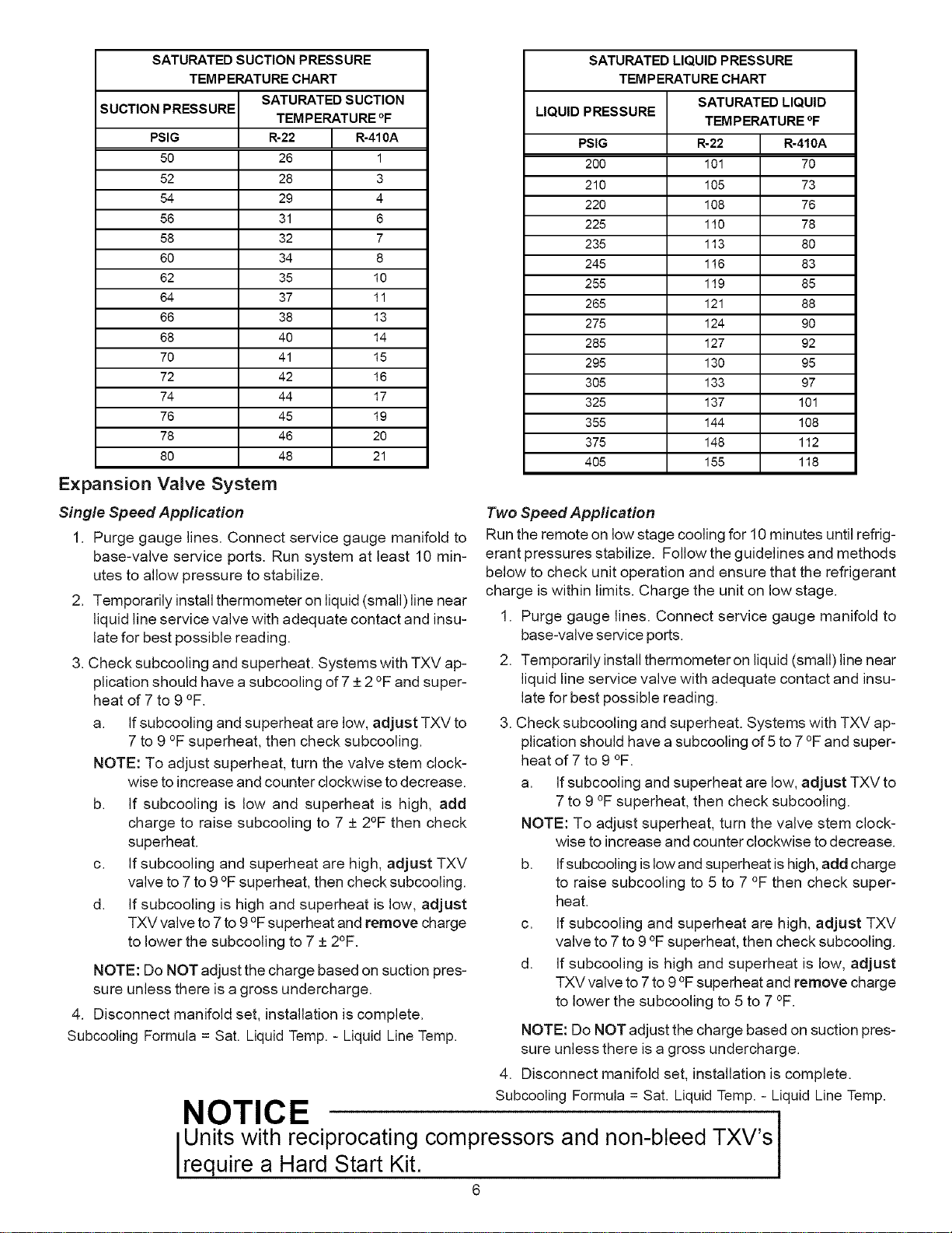
SATURATED SUCTION PRESSURE
TEMPERATURE CHART
SATURATED SUCTION
TEMPERATURE °F
R=22 R=410A
26 1
28 3
29 4
31 6
32 7
34 8
35 10
37 11
38 13
40 14
41 15
42 16
44 17
45 19
46 20
48 21
SUCTION PRESSURE
PSIG
5O
52
54
56
58
60
62
64
66
68
70
72
74
76
78
8O
Expansion Valve System
Single Speed Application
1. Purge gauge lines. Connect service gauge manifold to
base-valve service ports. Run system at least 10 min-
utes to allow pressure to stabilize.
2. Temporarily install thermometer on liquid (small)line near
liquid line service valve with adequate contact and insu-
late for best possible reading.
3. Check subcooling and superheat. Systems with TXV ap-
plication should have a subcooling of 7 _+2°F and super-
heat of 7 to 9 °F.
a. If subcooling and superheat are low, adjust TXV to
7 to 9 °F superheat, then check subcooling.
NOTE: To adjust superheat, turn the valve stem clock-
wise to increase and counter clockwise to decrease.
b. If subcooling is low and superheat is high, add
charge to raise subcooling to 7 _+2°F then check
superheat.
c. If subcooling and superheat are high, adjust TXV
valve to 7 to 9 °F superheat, then check subcooling.
d. If subcooling is high and superheat is low, adjust
TXV valve to 7 to 9 °Fsuperheat and remove charge
to lower the subcooling to 7 _+2°F.
NOTE: Do NOT adjust the charge based on suction pres-
sure unless there is a gross undercharge.
4. Disconnect manifold set, installation is complete.
Subcooling Formula = Sat. Liquid Temp. - Liquid Line Temp.
SATURATED LIQUID PRESSURE
TEMPERATURE CHART
SATURATED LIQUID
LIQUID PRESSURE
TEMPERATURE °F
PSIG R-22 R-410A
200 101 70
210 105 73
220 108 76
225 110 78
235 113 80
245 116 83
255 119 85
265 121 88
275 124 90
285 127 92
295 130 95
305 133 97
325 137 101
355 144 108
375 148 112
405 155 118
Two Speed Application
Run the remote on low stage cooling for 10 minutes until refrig-
erant pressures stabilize. Follow the guidelines and methods
below to check unit operation and ensure that the refrigerant
charge is within limits. Charge the unit on low stage.
1. Purge gauge lines. Connect service gauge manifold to
base-valve service ports.
2. Temporarily install thermometeron liquid (small)line near
liquid line service valve with adequate contact and insu-
late for best possible reading.
3. Check subcooling and superheat. Systems with TXV ap-
plication should have a subcooling of 5 to 7 °Fand super-
heat of 7 to 9 °F.
a. If subcooling and superheat are low, adjust TXV to
7 to 9 °F superheat, then check subcooling.
NOTE: To adjust superheat, turn the valve stem clock-
wise to increase and counter clockwise to decrease.
b. If subcooling islow and superheat is high, add charge
to raise subcooling to 5 to 7 °F then check super-
heat.
c. If subcooling and superheat are high, adjust TXV
valve to 7 to 9 °F superheat, then check subcooling.
d. If subcooling is high and superheat is low, adjust
TXV valve to 7 to 9 °Fsuperheat and remove charge
to lower the subcooling to 5 to 7 °F.
NOTE: Do NOT adjust the charge based on suction pres-
sure unless there is a gross undercharge.
4. Disconnect manifold set, installation is complete.
Subcooling Formula = Sat. Liquid Temp. - Liquid Line Temp.
NOTICE
Units with reciprocating compressors and non-bleed TXV's
require a Hard Start Kit.
6
Loading ...