Loading ...
Loading ...
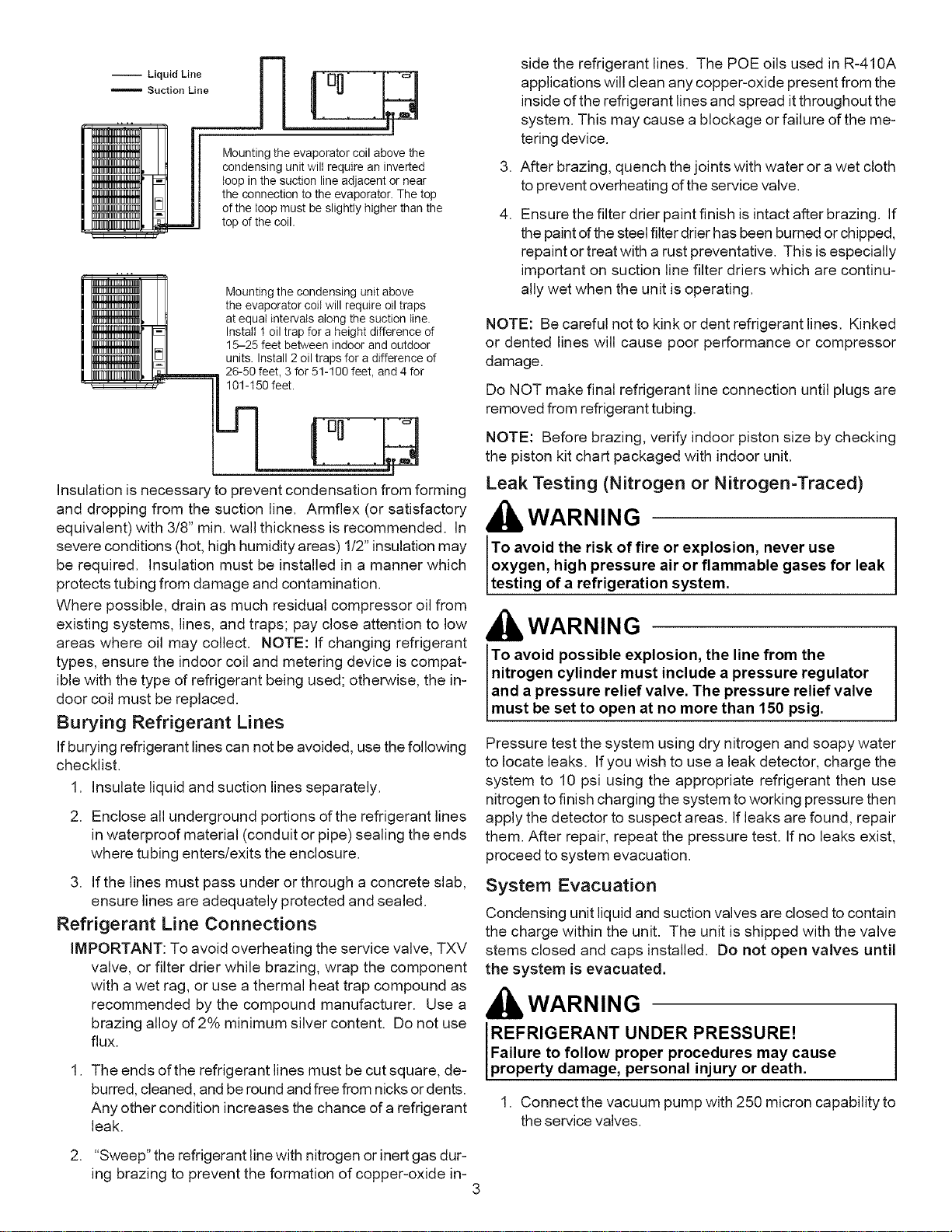
-- Liquid Line
Suction Line
Mounting the evaporator coil above the
condensing unit will require an inverted
loop in the suction line adjacent or near
the connection to the evaporator. The top
of the loop must be slightly higher than the
top of the coil.
Mounting the condensing unit above
the evaporator coil will require oil traps
at equal intervals along the suction line.
Install 1 oil trap for a height difference of
15-25 feet between indoor and outdoor
units. Install 2 oil traps for a difference of
m 26-50 feet, 3 for 51-100 feet, and 4 for
l_ _101-150 feet.
Insulation is necessary to prevent condensation from forming
and dropping from the suction line. Armflex (or satisfactory
equivalent) with 3/8" min. wall thickness is recommended. In
severe conditions (hot, high humidity areas) 1/2" insulation may
be required. Insulation must be installed in a manner which
protects tubing from damage and contamination.
Where possible, drain as much residual compressor oil from
existing systems, lines, and traps; pay close attention to low
areas where oil may collect. NOTE: If changing refrigerant
types, ensure the indoor coil and metering device is compat-
ible with the type of refrigerant being used; otherwise, the in-
door coil must be replaced.
Burying Refrigerant Lines
If burying refrigerant lines can not be avoided, use the following
checklist.
1. Insulate liquid and suction lines separately.
2. Enclose all underground portions of the refrigerant lines
in waterproof material (conduit or pipe) sealing the ends
where tubing enters/exits the enclosure.
3. If the lines must pass under or through a concrete slab,
ensure lines are adequately protected and sealed.
Refrigerant Line Connections
iMPORTANT: To avoid overheating the service valve, TXV
valve, or filter drier while brazing, wrap the component
with a wet rag, or use a thermal heat trap compound as
recommended by the compound manufacturer. Use a
brazing alloy of 2% minimum silver content. Do not use
flux.
1. The ends of the refrigerant lines must be cut square, de-
burred, cleaned, and be round and free from nicks or dents.
Any other condition increases the chance of a refrigerant
leak.
,
4.
side the refrigerant lines. The POE oils used in R-410A
applications will clean any copper-oxide present from the
inside of the refrigerant lines and spread itthroughout the
system. This may cause a blockage or failure of the me-
tering device.
After brazing, quench the joints with water or a wet cloth
to prevent overheating of the service valve.
Ensure the filter drier paint finish is intact after brazing. If
the paint ofthe steel filter drier has been burned or chipped,
repaint or treat with a rust preventative. This is especially
important on suction line filter driers which are continu-
ally wet when the unit is operating.
NOTE: Be careful not to kink or dent refrigerant lines. Kinked
or dented lines will cause poor performance or compressor
damage.
Do NOT make final refrigerant line connection until plugs are
removed from refrigerant tubing.
NOTE: Before brazing, verify indoor piston size by checking
the piston kit chart packaged with indoor unit.
Leak Testing (Nitrogen or Nitrogen-Traced)
kWARNING
To avoid the risk of fire or explosion, never use
oxygen, high pressure air or flammable gases for leak
testing of a refrigeration system.
WARNING
To avoid possible explosion, the line from the
nitrogen cylinder must include a pressure regulator
and a pressure relief valve. The pressure relief valve
must be set to open at no more than 150 ps g.
Pressure test the system using dry nitrogen and soapy water
to locate leaks. If you wish to use a leak detector, charge the
system to 10 psi using the appropriate refrigerant then use
nitrogen to finish charging the system to working pressure then
apply the detector to suspect areas. If leaks are found, repair
them. After repair, repeat the pressure test. If no leaks exist,
proceed to system evacuation.
System Evacuation
Condensing unit liquid and suction valves are closed to contain
the charge within the unit. The unit is shipped with the valve
stems closed and caps installed. Do not open valves until
the system is evacuated.
kWARNING
REFRIGERANT UNDER PRESSURE!
Failure to follow proper procedures may cause
property damage, personal injury or death.
1. Connect the vacuum pump with 250 micron capability to
the service valves.
2. "Sweep" the refrigerant line with nitrogen or inert gas dur-
ing brazing to prevent the formation of copper-oxide in-
3
Loading ...
Loading ...
Loading ...