Loading ...
Loading ...
Loading ...
Thermostat
Single-Stage Heating
w_t_
Single-StageCooiin
CAUTION
Use refrigerant certified to ARt standards. Used refrigerant
may cause compressor damage, and will void the warranty.
Most portable machines cannot clean used refrigerant to
meet ARI standards.
FURNACE OR
AIR HANDLER
REMOTE
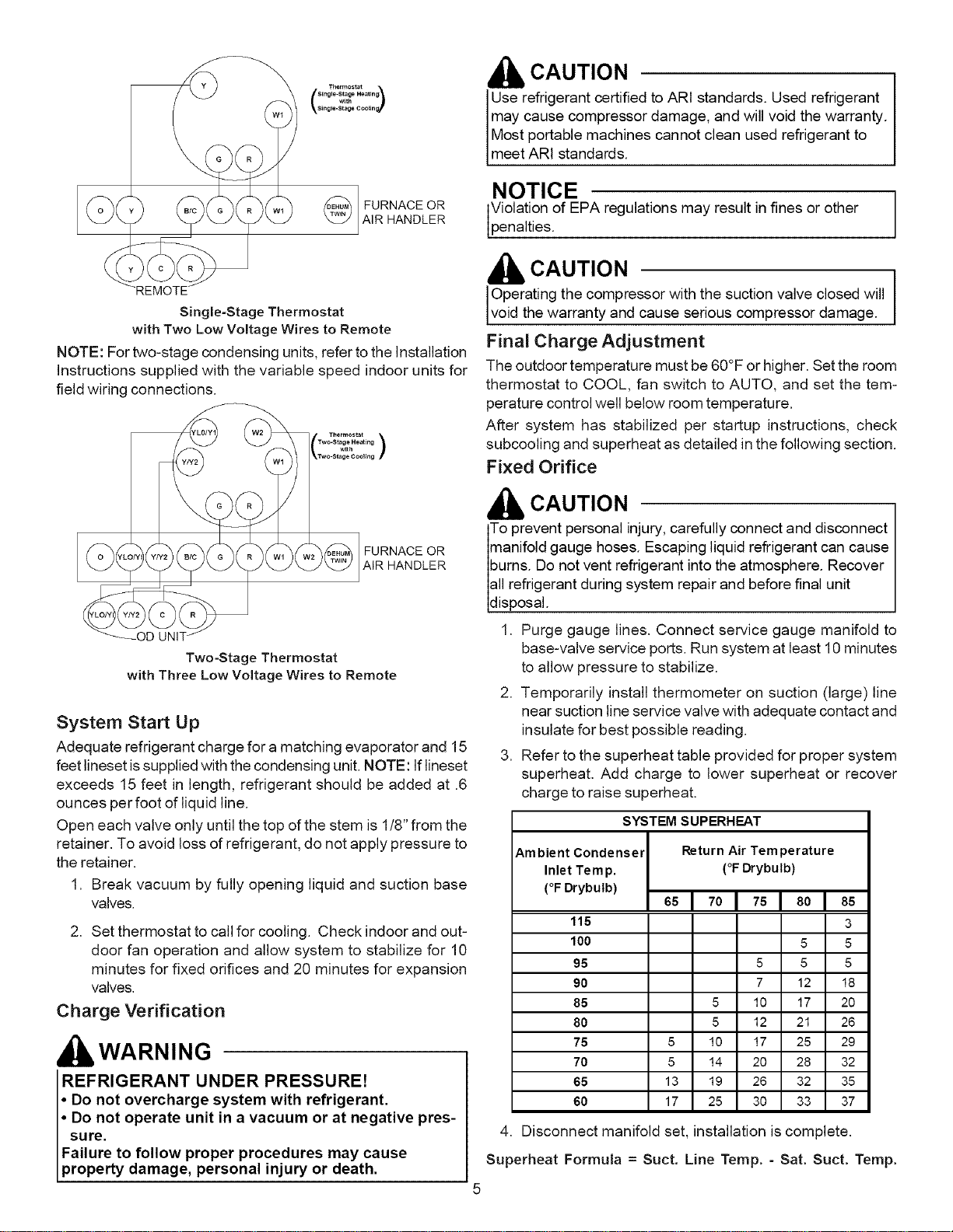
Single=Stage Thermostat
with Two Low Voltage Wires to Remote
NOTE: For two-stage condensing units, refer to the Installation
Instructions supplied with the variable speed indoor units for
field wiring connections.
NOTICE
Violation of EPA regulations may result in fines or other
pena t es.
CAUTION
Operating the compressor with the suction valve closed will
vo d the warranty and cause serous compressor damage.
Final Charge Adjustment
The outdoor temperature must be 60°F or higher. Set the room
thermostat to COOL, fan switch to AUTO, and set the tem-
perature control well below room temperature.
After system has stabilized per startup instructions, check
subcooling and superheat as detailed in the following section.
Fixed Orifice
FURNACE OR
AIR HANDLER
Two-Stage Thermostat
with Three Low Voltage Wires to Remote
System Start Up
Adequate refrigerant charge for a matching evaporator and 15
feet lineset issupplied with the condensing unit. NOTE: If lineset
exceeds 15 feet in length, refrigerant should be added at .6
ounces per foot of liquid line.
Open each valve only until the top of the stem is 1/8" from the
retainer. To avoid loss of refrigerant, do not apply pressure to
the retainer.
1. Break vacuum by fully opening liquid and suction base
valves.
2. Set thermostat to call for cooling. Check indoor and out-
door fan operation and allow system to stabilize for 10
minutes for fixed orifices and 20 minutes for expansion
valves,
Charge Verification
kWARNING
REFRIGERANT UNDER PRESSURE!
• Do not overcharge system with refrigerant.
Do not operate unit in a vacuum or at negative pres-
sure.
Failure to follow proper procedures may cause
property damage, personal injury or death.
CAUTION
To prevent personal injury, carefully connect and disconnect
manifold gauge hoses. Escaping liquid refrigerant can cause
burns. Do not vent refrigerant into the atmosphere. Recover
all refrigerant during system repair and before final unit
d sposa.
1. Purge gauge lines. Connect service gauge manifold to
base-valve service ports. Run system at least 10 minutes
to allow pressure to stabilize.
2. Temporarily install thermometer on suction (large) line
near suction line service valve with adequate contact and
insulate for best possible reading.
3. Refer to the superheat table provided for proper system
superheat. Add charge to lower superheat or recover
charge to raise superheat.
SYSTEM SUPERHEAT
Ambient Condenser
Inlet Tern p.
(°F Drybutb)
Return Air Temperature
(°F Drybutb)
5sl 701 751801
85
115 3
100 5 5
95 5 5 5
90 7 12 18
85 5 10 17 20
80 5 12 21 26
75 5 10 17 25 29
70 5 14 20 28 32
65 13 19 26 32 35
60 17 25 30 33 37
4. Disconnect manifold set, installation is complete.
Superheat Formula = Suct. Line Temp. - Sat. Suct. Temp.
Loading ...
Loading ...