

Visit warranty.waterdroplter.com and enter the product serial number.
The serial number is the last 7 digits of the barcode on the rear cover and packaging box.
This device complies with part 15 of the FCC Rules. Operation is subject to the
following two conditions: (1) This device may not cause harmful interference, and (2)
this device must accept any interference received, including interference that may
cause undesired operation. Any Changes or modications not expressly approved
by the party responsible for compliance could void the user's authority to operate
the equipment.
Find the installation video
Register 1-year manufacturer warranty*
* Please refer to Limited Product Warranty on Page 17
Search “Waterdrop D6 RO installation” on
Any questions, please contact us.
service@waterdroplter.com
1-888-352-3558 Mon-Fri 8:00 AM-5:00 PM (PST)
www.waterdroplter.com (live chat available)


Contents
Installation Instructions
Before Installation ··································································1
Product Introduction ·······························································2
Installation Tips ·········································································4
Installation Steps ····································································5
Step 1: Install the Feed Water Adapter
···············································5
Step 2: Install the Faucet
·································································6
Step 3: Install the Drain Saddle
························································7
Step 4: Position the RO System Housing
············································7
Step 5: Connect Tubing
································································8
Step 6: Connect the Faucet Power Cord
···························
······
············9
Step 7: Start up the System
············································
······
·········9
Owner’s Manual
Display and Operation ·····························································11
Section 1: Control Panel Display
····················································11
Section 2: Faucet Display
····························································11
Section 3: Filter Life Reminder
························································13
Section 4: Malfunction Display
······································· · · ···········13
Precautions ································· · · · ······································14
Troubleshooting ···································· ·······························16
Limited Product Warranty ·······················································17
1
Installation Instructions
Before Installation
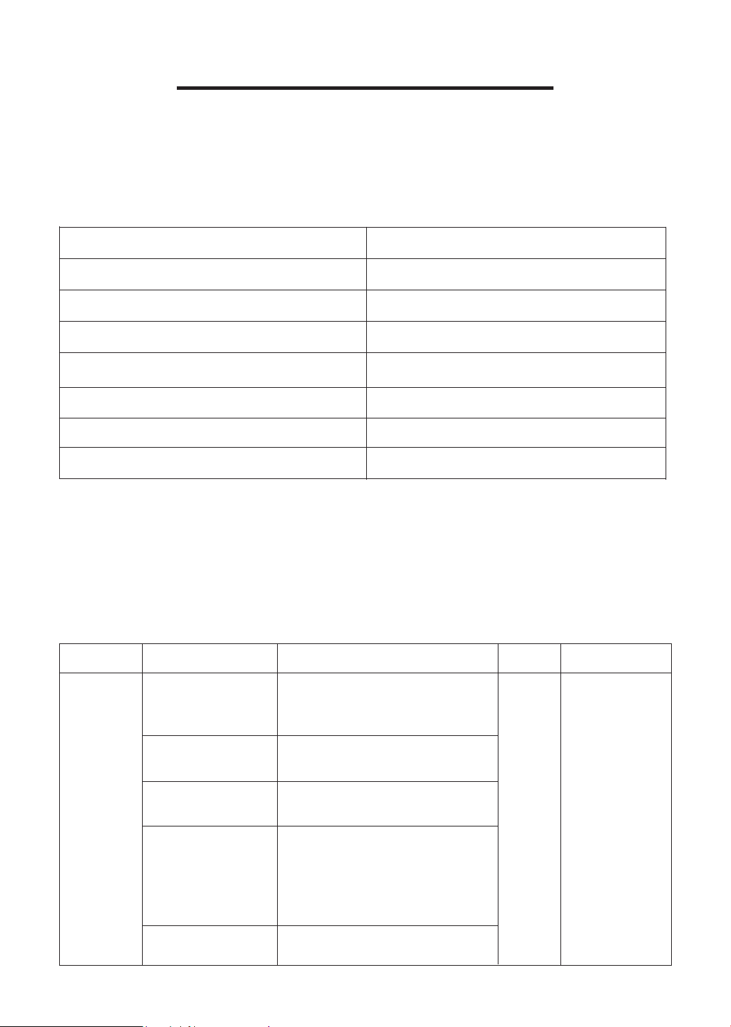
Product Specications
To achieve the optimal performance, it is highly recommended to use the system
within the operational parameters.
Filter Specications
Model Number
Name Filtration Media Purpose
Quantity
Recommended
Replacement Cycle
Total Filtration Capacity
Rated Voltage/Frequency
Rated Power
RO Membrane Working Pressure
Service Flow Rate
Feed Water Pressure
Feed Water Requirement
WD-D6-B
1,000 gallons
110~120V/60Hz
85W
58-115 psi
0.42 gal/min
Fist
Integral
Composite
Filter
14.5-87 psi
Municipal Tap Water
First PP
cotton layer
Filters out sediment, rust,
suspended solids, and other
large particles in water.
Removes organic matters,
chlorine, taste and odor.
Further removes suspended
matter and other impurities.
Improves the taste of water.
With a ltration accuracy of
0.0001 μm, it intercepts organic
matters and heavy metals in
water.
Activated carbon
block layer
1 12 months
Second PP
cotton layer
Reverse osmosis
membrane layer
Post-activated
carbon block layer
NOTE:
• The service ow rate is measured using an ambient temperature of 77±35.6°F, a
water temperature of 77±35.6°F, and a feed water pressure of 34.8±2.9 psi.
• If you are using well water as the source, please ensure that the feed water has
been through a pre-ltration system.

2
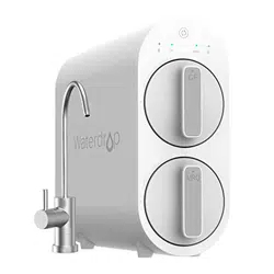
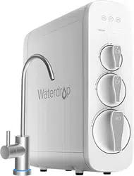
Product Overview
Parts List
Product Introduction
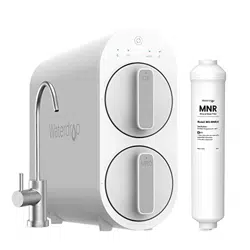
Fist Integral Composite Filter
Front Cover
Control Panel
Drain Saddle
Blue 1/4" PE Tubing
Red 1/4" PE Tubing
White 1/4" PE Tubing
Lock Clip
Smart Digital
Faucet
X 1 Set
X 1 Set
X 79"
X 79"
X 79"
System Housing
Feed Water Adapter
3/8" and 1/2"
X 1 Set
X 8 (2 Spare Clips)
3
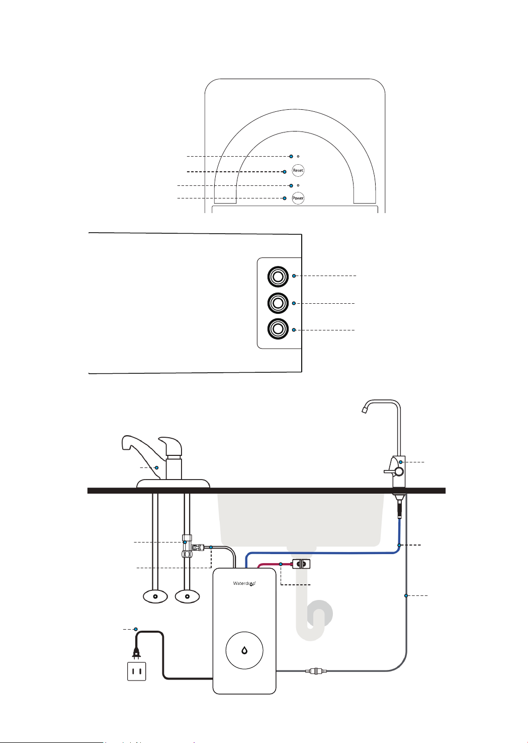
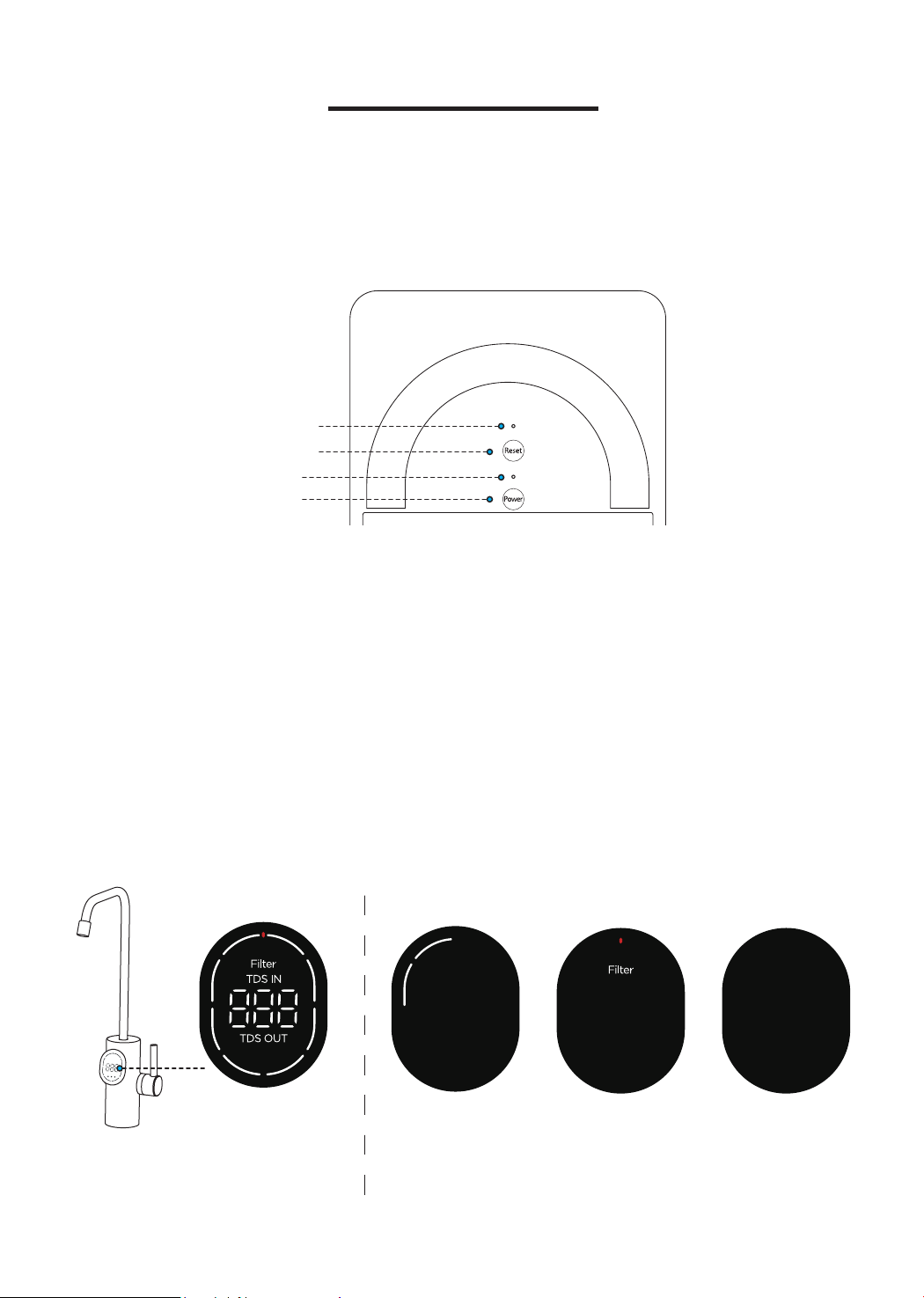
Drain Port
Inlet Water Port
Outlet Water Port
Filter Life Indicator
Power Indicator
Filter Reset Button
Power Button
Control Panel
Kitchen Faucet
Smart Digital
Faucet
Feed Water
Adapter
Drain Tubing
Inlet Water
Tubing
Power
ColdHot
Outlet Water
Tubing
Faucet Power
Cord
Press
Press
Pull
4
Installation Tips
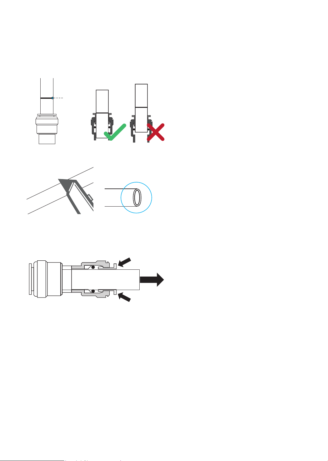
How to Use the Quick-Connect Fittings
To connect:
1. There is an existing mark (Figure 1)
at the end of the tubing that you can
use to conrm whether the tubing
is fully inserted into the tting. Push
the tubing into the tting until you
reach the mark on the tubing.
2. If the tubing is not fully inserted, it
will cause leakage. When the tubing
is fully inserted, put the blue lock clip
on the tting. It will lock the tubing in
place and prevent it from falling off.
3. If the tubing is too long, cut it to a
suitable length using a sharp utility
knife or pair of scissors. Cut the
tubing squarely and cleanly (Figure
2). Make sure the tubing is fully
inserted.
To disconnect:
1. Remove the blue lock clip from the
tting.
2. Use your thumb and index nger
to press down on the lock sleeve.
Use your other hand to pull out the
tubing from the tting (Figure 3).
NOTE: Please do not pull out the
tubing directly, or else it will damage
the tting and cause leakage.
Figure 2
Figure 1
Figure 3
Mark for
Full Insert
Cut Cleanly
and Squarely
How to Drill a Hole into Your Sink or Countertop (Optional)
NOTE:
• Please conrm if there is an existing hole available to install the faucet. If not,
please drill a hole in accordance with the following steps.
• If the countertop is thicker than 2.95 inches, the faucet cannot be installed. It’s
highly recommended to watch the YouTube video “How to Drill Faucet Holes”
for a better understanding of the process. There is also a sticker for your
reference when you drill the hole. Remember to wear safety glasses to protect
your eyes while drilling the faucet hole.

5
Step 1:
Install the Feed Water Adapter (3/8" or 1/2")
Installation Steps
NOTE:
• Before installation, remove the RO system from the box and choose an easy-
to-access area under the sink to place it. An adequate at area is necessary to
allow the system to rest securely. Do not lay it on its side, on its back, or upside
down.
• Also before installation, ensure that there is a power outlet in the cabinet or
on the wall connected to the lower cabinet space. Additionally, ensure that the
system does not share the same power outlet as the garbage disposal.
• The RO system must be connected to the COLD water supply ONLY.
• Do not install the system where it will be exposed to direct sunlight or harmful
chemicals, nor in any place where it may be damaged.
• Do not install the system near any heat source.
• Do not install the system outdoors.
Prior to installation, it is highly recommended to watch the video “Waterdrop
D6 RO
installation
” on .
1. Choose a diamond core bit for granite, and a carbide drill bit for stainless steel.
Do not use a hammer drill on natural stone, glass, or ceramic.
2. Glue the sticker to your sink or countertop, and drill a hole referring to the size
shown on the sticker (1⅜").
3. Make an indent with a center punch on a stainless-steel sink before drilling to
help guide the bit.
4. Be careful when drilling on a porcelain sink, as it can be easily chipped. Apply
downward pressure rmly to the bit until breaking through the surface.
5. Starting at the lowest speed, hold the drill straight with rm pressure to prevent
the bit from walking on the counter.
6. Once breaking through the surface, swirl the drill a little to apply pressure in a
circle evenly.
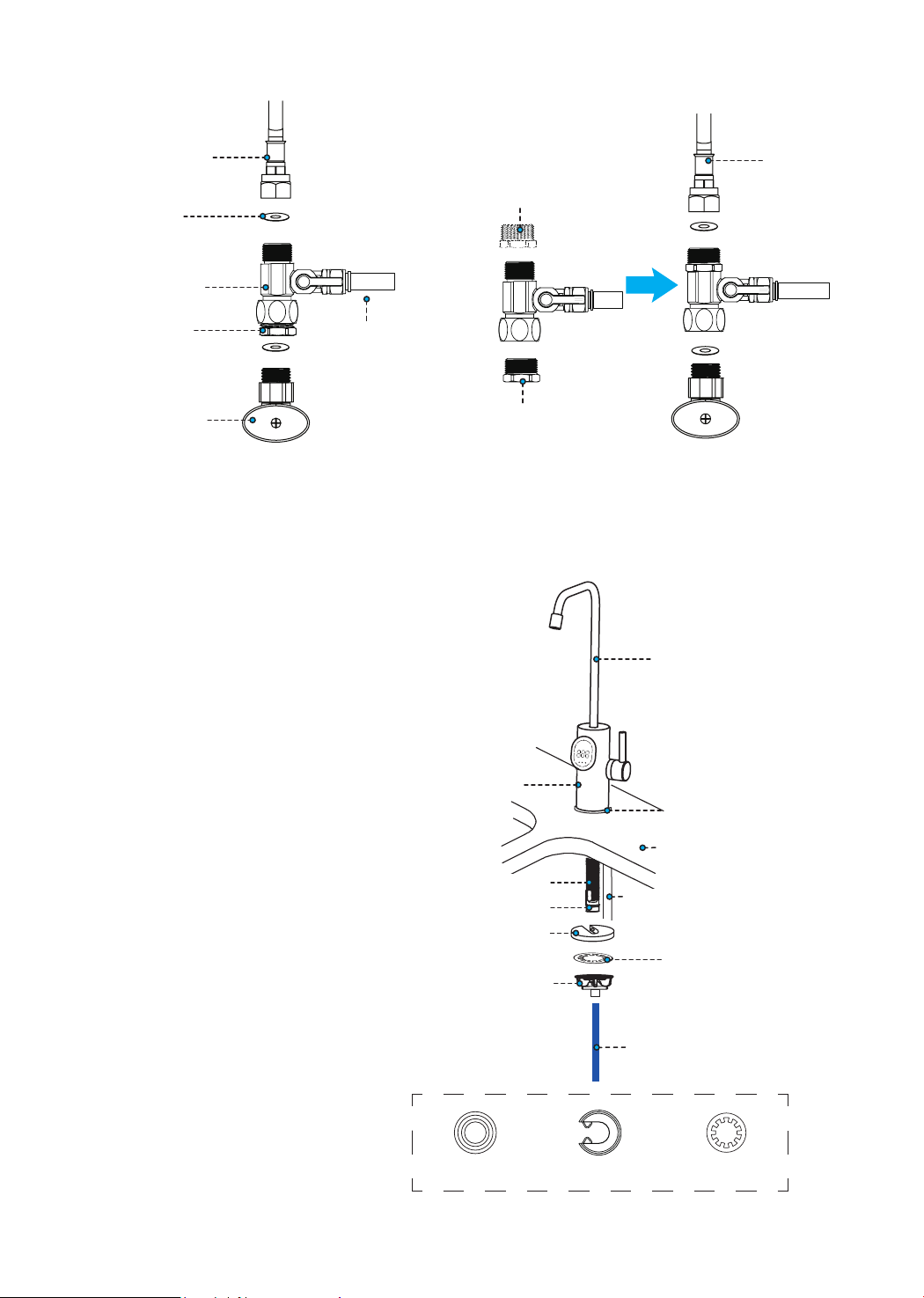
1. Shut off the water supply. Turn on the faucet to release the water pressure.
NOTE: Make sure the water has stopped before proceeding to the next step.
Use a towel or bucket to catch any excess water.
2. Disconnect the cold water pipe from the cold water supply valve.
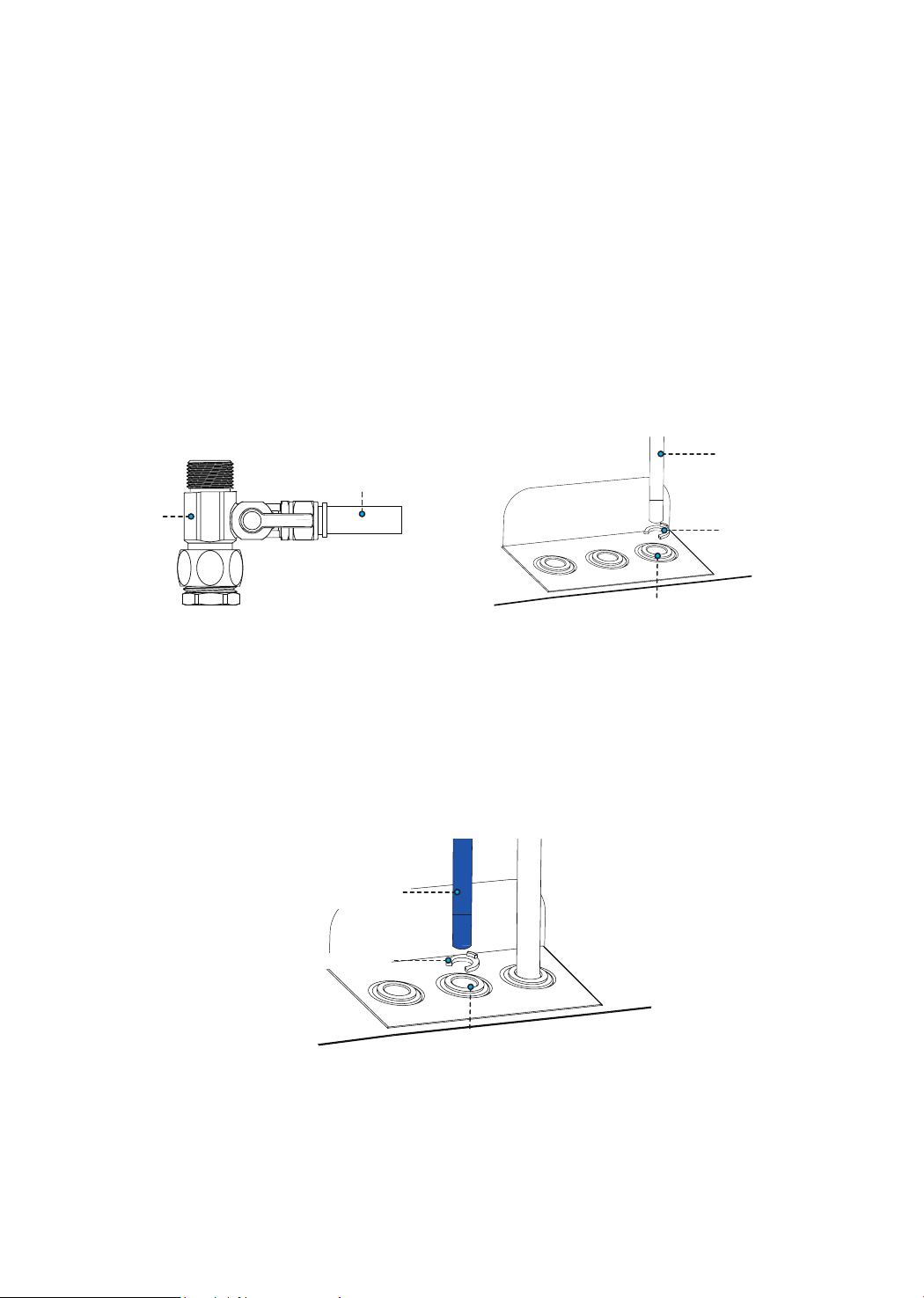
3. Connect the white 1/4” inlet water tubing to the feed water adapter and pop the
lock clip on the tting.
NOTE: Make sure it is fully inserted until you reach the mark on the tubing.
4. Tighten the converter. Twist the feed water adapter onto the cold water supply
valve (with its washer) and tighten it using an adjustable wrench (Figure 4).
NOTE: If the cold water pipe is 1/2”, unscrew the converter from the A end of
the feed water adapter, and then screw it on the B end of the feed water adapter
(Figure 5). Next, follow step 4.
5. Twist the cold water pipe (with its washer) onto the feed water adapter and
tighten it with an adjustable wrench.
6
Step 2:
Install the Faucet
NOTE: If there is no hole in
your kitchen sink or countertop,
you have to drill one (1⅜")
or use the hole in the soap
dispenser. Refer to Page 4.
3/8"
Cold Water Pipe
1/2"
Cold Water Pipe
Washer
Converter
Unscrew
1/4'' Inlnet Water
Tubing
Feed Water
Adapter
Cold Water
Supply Valve
Figure 4 Figure 5
Screw
B
A
Faucet Body
Countertop
Mounting Washer 1
Mounting Washer 3
Quick-Connect Fitting
Faucet Spout
Faucet Stem
Mounting Washer 2
Nut
Faucet Power Cord
1. Insert the faucet stem
and power cord into
mounting washer 1.
2. Insert the faucet stem
and power cord into the
hole on the countertop.
Fix mounting washer 1
on the countertop.
3. Under the sink, put
mounting washer 2 and 3
on the faucet stem. Slip
on the nut and tighten it.
4. Insert one end of the
blue 1/4” PE tubing into
the quick-connect tting
on the faucet and pop in
the lock clip on the tting.
*Mounting Washer 1 Mounting Washer 2 Mounting Washer 3
Outlet Water Tubing
*NOTE: Please use the black mounting washer that has the groove. You
won’t need the other black mounting washer.
7
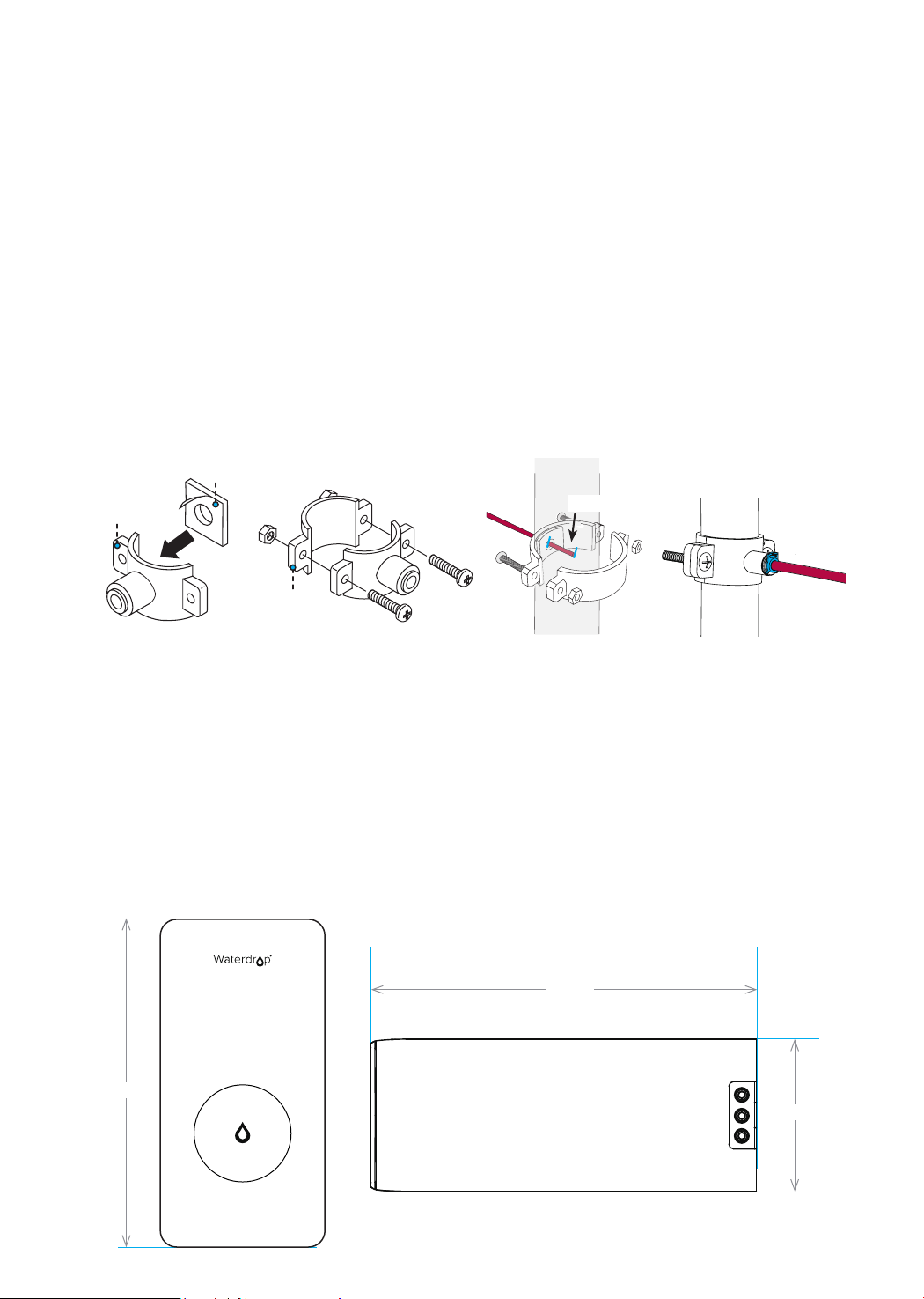
Step 3:
Install the Drain Saddle
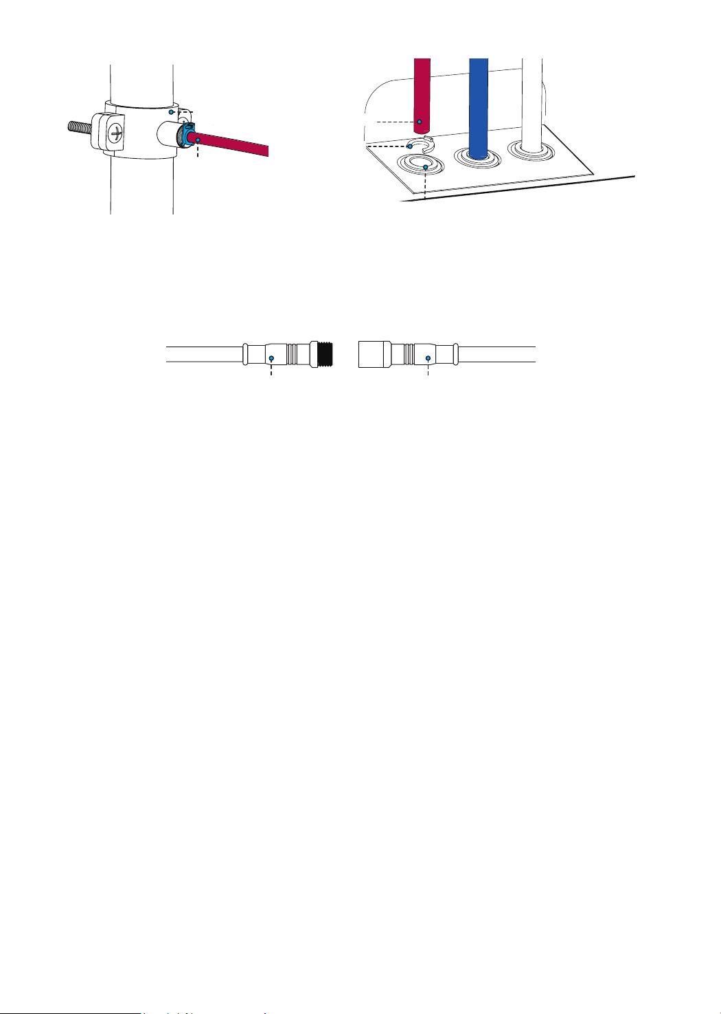
1. Stick the foam seal on the front plate of the drain saddle. Ensure that the hole
of the foam seal is aligned with the hole of the front plate (Figure 6). Choose a
spot on the drainpipe that is convenient for installing the drain saddle.
NOTE: It’s recommended to install the drain saddle on the vertical drainpipe.
2. Drill a 1/4" hole in the drainpipe. Be sure not to penetrate the opposite side of
the pipe.
3. Slip the front plate on one end of the tubing (without a mark) and insert the
tubing into the drilled hole for about 0.6" (Figure 7).
4. Position the back plate on the drainpipe by tightening the screws and nuts
evenly while leaving the tubing in the hole.
5. Pop the lock clip onto the tting to secure the connection (Figure 8).
NOTE: In some areas, the drain tubing must be connected to the drainpipe
through the air gap. Consumers must purchase air gap accessories separately.
5.98"
15.98"
Step 4:
Position the RO System Housing
Ensure that there is sufcient space under the countertop to install the system
(15.98" *5.98" *11.97"). Set aside 2 inches of space around the system to avoid
placing the system against the cabinet.
NOTE: Position the front panel facing toward you, which will be convenient for
future lter replacement and indicator checking. You can also adjust the placement
direction of the RO system according to the layout under the sink.
11.97"
Figure 6
Figure 7
Figure 8
Foam Seal
About 0.6"
Back Plate
Front Plate
Step 5:
Connect Tubing
NOTE:
• Conrm the tubing length you need rst. Then cut the tubing if it is too long,
referring to “How to Use the Quick-Connect Fittings” on page 4.
• Before connecting the PE tubing to the system, remove the plug from the water
port. Press and hold the lock sleeve while pulling out the plug.
2. Install the Outlet Water Tubing
Inlet Water Port
3. Install the Drain Tubing
• Connect the red 1/4" PE tubing to the drain saddle.
• Insert the other end of the tubing into the drain port and pop the lock clip on the
tting.
NOTE: Make sure it is fully inserted to the point where you reach the mark on
the tubing.
1. Install the Inlet Water Tubing
• Identify the white 1/4" PE tubing that has been connected to the feed water
adapter.
• Insert the other end of the tubing into the inlet water port and pop the lock clip
on the tting.
NOTE: Make sure it is fully inserted until you reach the mark on the tubing.
Inlet Water
Tubing
Lock Clip
8
Feed Water
Adapter
Inlet Water Tubing
• Identify the blue 1/4” PE tubing.
• Insert the other end of the tubing into the outlet water port and pop the lock clip
on the tting.
NOTE: Make sure it is fully inserted until you reach the mark on the tubing.
Outlet Water
Tubing
Lock Clip
Outlet Water Port
9
Step 7:
Start up the System
Step 6:
Connect the Faucet Power Cord
Faucet Connector System Connector
Connect the faucet to the system: Insert the power cord which is attached to the
RO faucet into the connector at the back of the housing.
Drain Saddle
Drain Tubing
Drain Tubing
Lock Clip
Drain Port
1. Turn on the cold water supply valve. Check for leaks.
2. Insert the power plug into the socket.
NOTE:
• The system will be powered on and beep 5 times. The lter indicator light will
ash 5 times and then stay on.
• If the system can’t be powered on after you insert the power plug, check the
power under the sink, as this mostly occurs when the power under the sink
is powered off. Also, check the connection between the power plug and the
power outlet, and ensure that the system has been plugged correctly into the
power outlet, as this may occur in a few cases. To test if there is a problem
with the system itself, just pick up the system and try another power outlet.
Please contact us if the system can’t be powered on. We will help you gure
it out.
• Every time you power on the system, it will automatically ush for 25
seconds. The reset button and power button will ash alternately. If you turn
on the faucet at this time, the outlet water ow will be slow. After ushing, the
reset button and power button will be on, and the outlet water ow will return
to normal.
3. Turn on the faucet, and allow it to run for 20 minutes. After ushing, the system
is ready for use. The system will drain residual water after every use to ensure
the system’s service life and ltered water quality. Every time you turn on the
faucet, the system will need some time to dispense water. There may be a
3-second delay before water dispenses, which is normal.
NOTE:
• Be sure to carefully check the tightness of each part of the system while
ushing. Ensure that all the tubing is installed correctly and completely. Make

10
sure there are no leaks at the joints, ttings, valves, or tubing connections.
• The water will be undrinkable during the ushing process. The water might
appear black at rst.
• You will need to do the timekeeping for the 20-minute ushing yourself. Note
that when the system continuously works for over 40 minutes, it will enter
timeout protection mode. The lter indicator light will ash and the system
will not be able to dispense water. Press the power button for 3 seconds. The
lter indicator light will turn off. Then press the power button for 3 seconds.
The system will return to normal.
4. Before turning off the faucet, make sure the ushing is complete and that there
are no leaks in any of the parts.
NOTE:
• When the system stops operation for 10 minutes, it will switch to self-ushing
mode. The system will automatically ush for 20 seconds and then switch to
standby mode. After 10 minutes, the system will not automatically ush again.
• When the system stops dispensing water for 24 hours, it will switch to self-
ushing mode. The system will automatically ush for 90 seconds and then
switch to standby mode. The timer will reset. After 24 hours, the system will
not automatically ush again.
Owner’s Manual
Display and Operation
• Powering on mode: The lter life indicator ashes 5 times.
• Standby/Dispensing water mode: The lter life indicator stays on. When the
lter expires, the lter life indicator ashes.
• Energy-saving mode: When the system stands by for 3 hours, it will switch to
energy-saving mode. All indicators will be off. When you press a button or turn
on the faucet, the system will exit energy-saving mode.
1. The system is powered on: All indicators ash 5 times (Figure 9).
2. The faucet is turned off: When the RO system is powered on, the screen will
show the lter’s status. If there is no operation for 1 minute, the screen will switch to
standby mode (Figure 10).
Section 1: Control Panel Display
11
Section 2: Faucet Display
Smart Digital
Faucet
Smart Display
Screen
When the lter has
not expired, the
screen will show
the remaining life
of the lter.
The lter has
expired.
Standby mode
(no operation for
1 minute)
Filter Life Indicator
Power Indicator
Filter Reset Button
Power Button
Figure 9
Figure 10
12
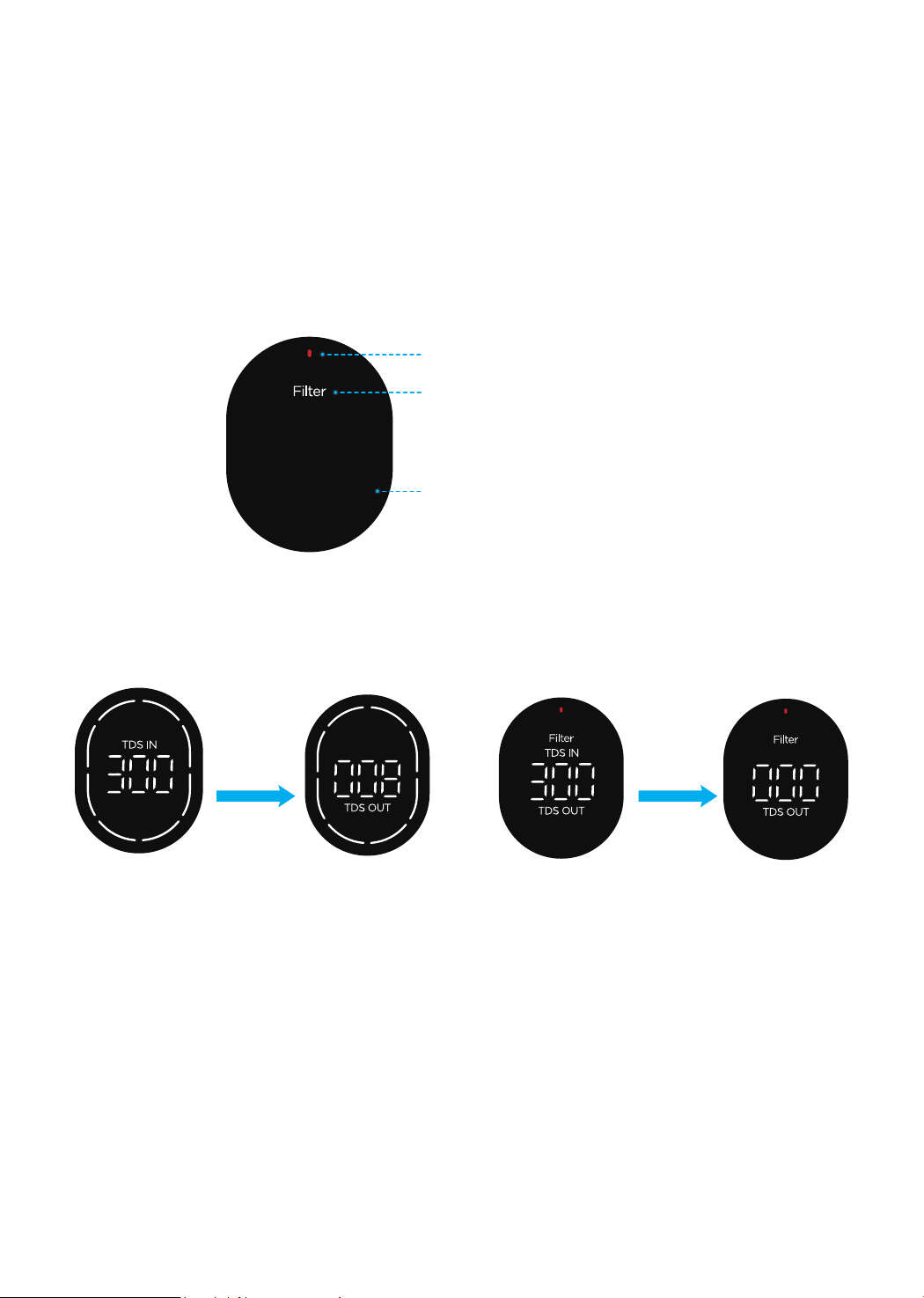
3. Filter life reminder (when the faucet is turned on)
• If the lter has not expired, every segment of the ring light will be on. Then, they
will be off one by one, and the remaining segments indicate the life of the lter.
NOTE:
When there are two segments of the ring light on the screen, the life
of the lter remains about 4%-15% (40-150 gallons), which may vary based on
your water conditions. It is recommended that you prepare a replacement lter in
advance.
• If the lter has expired, the ring light will be off. Also, the lter replacement
indicator will turn red and the screen will display “Filter” after ashing 3 times
(Figure 11).
NOTE:
Every time you turn on the faucet, the TDS meter will display the TDS
value of unltered water (“TDS IN”) for the rst 2 seconds. After 2 seconds, it will
display the TDS value of ltered water (“TDS OUT”). (Figure 12)
4. Malfunction display
• E9: If the faucet is powered on and does not receive the correct data for 5
seconds, the screen will display “E9” and then switch to standby mode after 1
minute.
NOTE:
Check the power cord of the faucet to see whether it is plugged in. If
not, plug it in. Check on whether the power cord is damaged. If so, please contact
Waterdrop customer service.
• E6: When the system continuously works for over 40 minutes, it will enter
timeout protection mode. The screen will display “E6”.
NOTE:
Press the power button for 3 seconds. The lter indicator light will turn
off. Then press the power button for 3 seconds to power on the system. It will
a. The lter has not expired. b. The lter has expired.
Switch after
2 seconds
Switch after
2 seconds
The lter replacement indicator turns red.
The screen displays “Filter”.
The ring light is off.
Figure 11
Figure 12

Turn off the water supply and turn on the faucet. Press the power button for 3
seconds to turn off the power. Replace the lter according to the following steps.
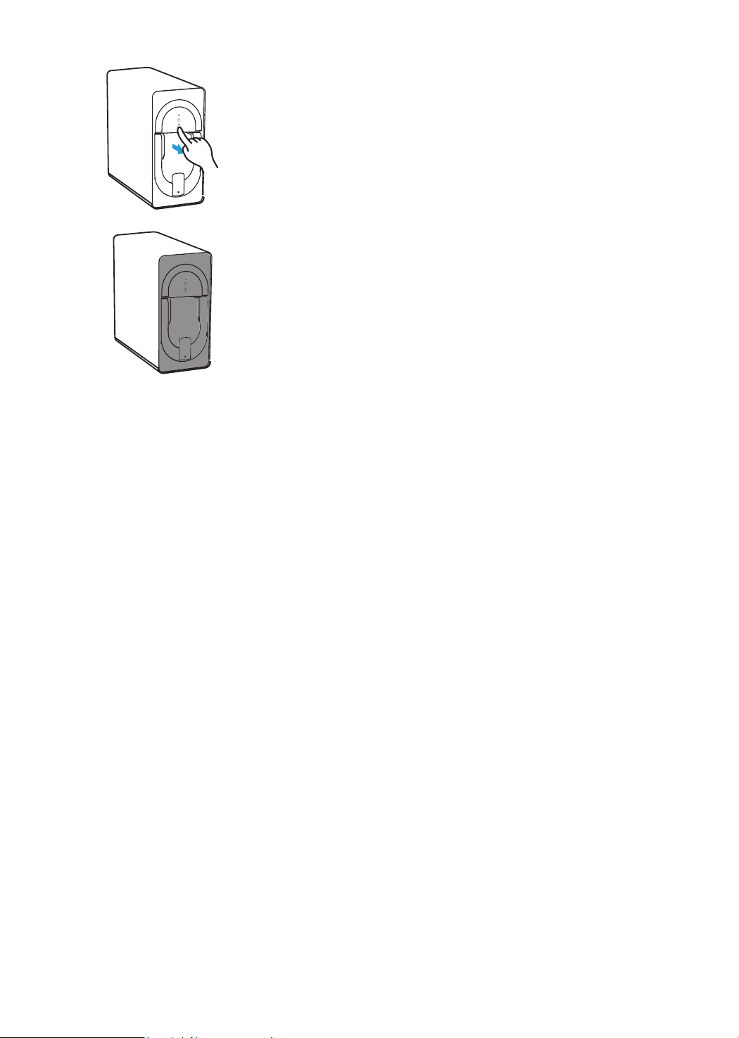
Section 4: Filter Replacement Guide
1. Remove the front cover.
3. Insert a new lter and push down
the locking handle. (You will have to
press hard with your hands.)
2. Pull up the locking handle (a)
and use the lter handle to pull out
the expired lter(b).
a
b
4. When you hear a snap and the locking
handle stays in place, the lter is locked.
The lock, locking handle, and front end
must be on the same vertical line.
Fist Integral Composite Filter has a service life of 12 months. Please replace the
lter when the situation shown in the gure occurs.
Section 3: Filter Life Reminder
The lter indicator light ashes.
Filter Life Indicator
13
automatically ush for 25 seconds. If you turn on the faucet during ushing, the
outlet water ow will be slow, which is normal.
• EA: When the TDS display is abnormal, the screen will display “EA”.
NOTE:
You will need to unplug the power and plug it in again. If the problem has
not been resolved, please contact Waterdrop customer service.
14
After resetting the lter, turn on the faucet and ush the system for 20 minutes until
the water eventually turns clear.
NOTE: If you need to replace the lter when the life has not expired, press the
reset button for 3 seconds. The lter indicator light will ash. Then press the button
for 3 seconds again. The timer will reset. The lter reset is complete.
Warning:
• Do not store the system in a location exposed to direct sunlight, as this may
cause the aging of the product parts. Do not store or expose the system to an
area below 32°F.
• Do not store the system near appliances with strong magnets, which can cause
re, product damage, or circuit malfunction. Wet or dusty areas may cause
circuit damage.
• Do not place heavy objects on the system.
• Do not allow young children to operate, touch, or climb on the system.
• To prevent the system from breaking when you unplug it, do not pull the power
cord directly. Keep the power plug clean and do not plug or unplug the system
with wet hands. Do not use a step-up transformer to connect to the power plug.
• Do not place ammable or volatile substances near the system.
• Do not place the system near heat sources or re.
Precautions
5. After replacing the lter, press the power button for 3
seconds. The indicator light will be on and you will hear a
“ding” sound. (Note: The system will automatically ush
for 25 seconds, and the reset button and power button will
ash alternately. 25 seconds later, these two buttons will
be on.) After ushing, press the reset button for 3 seconds.
Release it when you hear a “ding” sound. The indicator light
will change from ashing to constant.
6. Put back the front cover and press the button to
lock it. The lter reset is complete.
Caution:
• Do not crush, fold, knot, or damage the power cord.
• When the inlet water does not meet municipal tap water standards (including
large amounts of sediment, excessive oxygen in the water, etc.), a pre-
treatment device should be installed before the installation of this system.
• The feed water pressure of this system is 14.5-87 psi. If the water pressure is

• Applicable water quality: municipal tap water.
• The feed water pressure of this system is 14.5-87 psi. When the water pressure
is lower or higher, install a pressurizer or a pressure reducer accordingly.
• The recommended temperature range of the product is 39-100°F. Do not install
the system where the ambient temperature and water temperature are higher
than 104°F or below 32°F.
• Check whether the tubing connected to the system is incorrect and aging.
• Make sure all tubing is fully inserted to the point where you reach the mark on
the tubing.
• Use only authorized WD-D6-B parts and lters.
• Check the tightness of the feed water adapter and make sure there is no water
leakage.
• When the quick-connect tting leaks, do not replace only the lock clip. You must
replace the entire quick-connect tting.
• Do not omit any lock clips.
• Do not lay the system on its side, on its back, or upside down.
• Do not use a lter that has not been ushed. Flush the new lter for 20 minutes.
• Do not cut the tubing with tools other than a utility knife. Do not bend the tubing.
• Use the new quick-connect ttings that come with the system. The old quick-
connect ttings cannot be reused.
• Do not insert the drain tubing into the sewer. It must be connected to the
drainpipe using the drain saddle.
• A xed power socket of 110V is required. Ensure that the power socket and
adapter are in a dry place indoors to prevent moisture from accumulating in the
system.
Installation Precautions
15
lower or higher, install a pressurizer or pressure reducer accordingly.
• The ow rate will decrease when the ambient temperature is low, which is an
inherent characteristic of the lter.
• When the system is dispensing water, there will be a slight vibration and noise,
which is normal.
• This system is designed for indoor use only. A oor drain should be located
within 1.5 meters of the system to avoid loss caused by water leakage and poor
drainage.
• If the system will not be used for a long time, turn off the power and the feed
water adapter. Flush the system for 5 minutes before using it again.
NOTE: In the event of a water outage or pipeline maintenance, turn off the power
and the feed water adapter. When the water supply returns to normal, turn on other
faucets to drain the sediment. Then turn on the feed water adapter. Otherwise, a
large amount of sediment may block the lter. Replace and ush the lter regularly.

16
• The System Cannot Be Powered on After You Insert the Power
Plug
a. Check the power under the sink, as this occurs primarily when the power under the
sink is powered off. Also, check the connection between the power plug and the
power outlet to ensure that the system has been correctly plugged into the power
outlet. To test whether there is a problem with the system itself, simply pick up the
system and try another power outlet. Please contact us if the system cannot be
powered on. We will help you gure it out.
• No Output Water from the Faucet
a. The lter is expired: Check the lter life indicator to conrm whether the lter must
be replaced; if it does, replace it immediately.
b. Low water pressure: Check and conrm that the water pressure is between 14.5 psi
and 87 psi.
c. Water supply is off: Turn on the feed water adapter or the water supply valve.
d. Incorrect lter installation: Reinstall the lter and make sure it is tted into
properly.
e. A tubing is crimped: Check all the tubing and remove any crimps.
• Low Water Flow at the Faucet
a. A tubing is crimped or there is a leak from the tubing connection: Check to
ensure that all tubing is installed correctly and completely.
b. The lter is expired: Check the lter life indicator to conrm whether the lter
needs to be replaced; if it does, replace it immediately.
c. Low water temperature: Be sure to use the system at a temperature of 39-100°F.
d. The lter has been clogged: If you are using well water as the source, please
ensure that the feed water has been through a pre-ltration system. Otherwise,
large particles in the well water will easily clog the lter and shorten the lter life.
Troubleshooting
• High TDS in the Filtered Water
When working properly, the system will provide a 90%+ TDS rejection rate (tested
under standard laboratory conditions). If the TDS reading is high, the following are
possible causes:
a. The system hasn’t been used in a while. Turn on the faucet and allow the water
to run for a while. The TDS reading will return to normal.
b. The lter is expired: Check the lter life indicator to conrm whether the lter
needs to be replaced; if it does, replace it immediately.
c. The drain tubing may be crimped or clogged: Check and remove the crimps.
Realign the drain saddle and the drainpipe.
d. The source water may have a high TDS: Test the source water and the ltered
water. The ltered water’s TDS should be about 5%-10% of your source water’s
TDS. This is a normal range. If the source water has a high TDS, it may reduce
the system’s service life. When the ltered water’s TDS creeps up to 15%-20%
of the source water’s TDS, please perform routine lter replacement.

17
Limited Product Warranty
The warranty of our product covers defects in materials and workmanship from
the original date of purchase. During the warranty period, we will replace or repair
any part which is deemed to be defective, if the product has not been subjected to
tampering, alteration, lack of regular maintenance or improper use after delivery.
The cost of repair or replacement under those excluded circumstances shall be
borne by the consumer. This limited warranty does not cover the following items:
lters and all other parts or components that require regular replacement as a
result of ordinary usage. This limited warranty only applies if the system is installed,
used, and maintained in compliance with all instructions and requirements
enclosed with the system.
This limited warranty shall only be valid if:
1. The feed water pressure is no less than 14.5 psi and no more than 87 psi.
2. The feed water temperature must be no less than 39
°F
and no more than 100
°F
.
3. The feed water must have a pH between 6.5 and 8.5.
4. Turbidity must be less than 1.0 NTU.
Any information or suggestions with respect to our product concerning applications,
• The System Hasn’t Been Used in a While
a. Deposits in the tubing may block the lter. Before using the system, turn on
the regular tap and allow the water to run for a while. Turn on the ltered water
faucet and ush the system.
• Filtered Water from the Faucet Tastes Like Tap Water
a. Incorrect tubing installation: Make sure the drain tubing is not connected to the
faucet.
b. The lter is expired: Check the lter life indicator to conrm whether the lter
needs to be replaced; if it does, replace it immediately.
• Water Leakage
a. Check all the joints, ttings, and tubing connections to locate the leakage. Make
sure the lter is well installed.
• Loud Sound from the RO System
The sound will not exceed 55 dB, which is a standard level for everyday life (55
dB is tested under standard laboratory conditions and the feed water pressure is
between 14.5 psi and 87 psi). A loud sound may be caused by any of the following:
a. The system is not positioned in a at area. Make sure the system is placed
smoothly without shaking.
b. The system is placed against the cabinet. Do not place the system against the
cabinet. The system may vibrate when it is in operation.
c. The water pressure is unstable. Check and conrm that the water pressure is
between 14.5 psi and 87 psi. The sound will decrease when the water pressure
becomes stable.

specications, or standards is provided solely for your convenience.
The quality of water supplies may vary seasonably or over a period of time. Your
water usage may vary as well. The manufacturer shall assume no liability for the
determination of the proper equipment necessary to meet your requirements, and
we do not authorize others to assume such obligation on our behalf. You must
verify and test the suitability of any information with respect to the product for your
specic application.
This limited warranty shall be void if:
1. The cartridge lters are not replaced according to the recommended
maintenance schedule.
2. The product is purchased someplace other than our ofcial website or from
someone other than our authorized dealers, as in such cases we cannot verify
or guarantee the integrity or authenticity of the product.
Our sole obligation under this warranty shall be the repair or replacement of a
non-conforming product or parts of this product or, at our option, the return of the
product and a refund of the purchase price. Our obligation does not include the
cost of transportation. We are not responsible for damage in transit. A claim for
such damage should be presented to the carrier by the customer.
The warranties set forth herein are the only warranties we have made with respect
to the product. We make no warranties, expressed or implied, including, but not
limited to, any warranties of tness or merchantability, except as expressly set forth
above.
NOTE: In case some states do not allow limitations on how long an implied
warranty lasts, you may choose to return the system. If you choose to keep
it, you agree that the above limitations still apply to you.
Warranty Registration
Please visit our website warranty.waterdroplter.com and go to the “Warranty
Registration” tab to register your product for the warranty.
We offer a 30-day money back guarantee, a 1-year manufacturer warranty,
and lifetime tech support for all our products. Please be sure to ll in the order
information upon registration of your system. For any questions and concerns
about the product, please feel free to contect us. Your satisfaction is our top
priority!
How to Contact Us
service@waterdroplter.com
1-888-352-3558 Mon-Fri 8:00 AM-5:00 PM (PST)
www.waterdroplter.com (live chat available)