
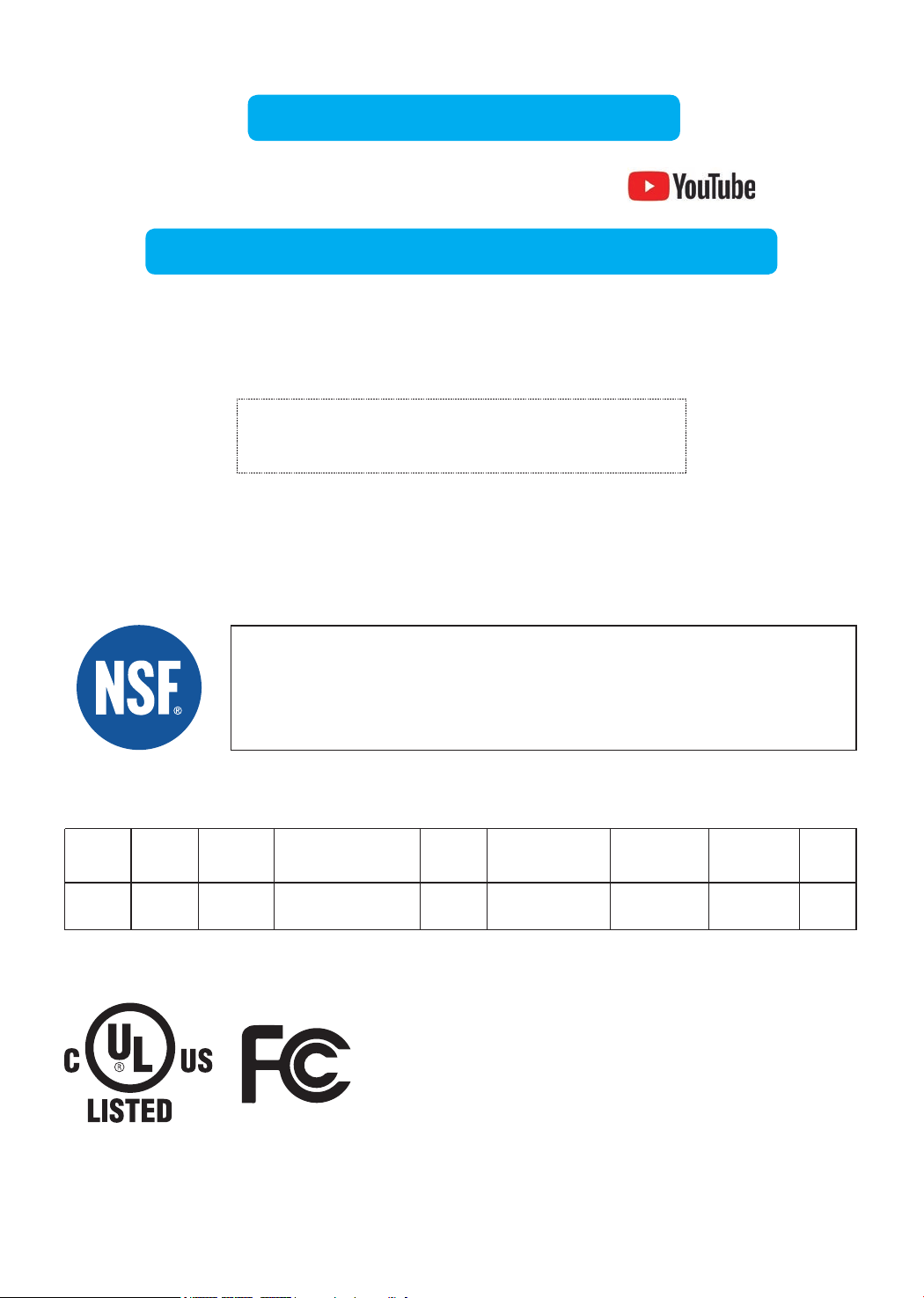
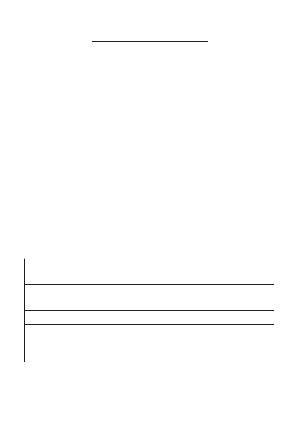
TDS 750 mg/L 92.90% 62 mg/L 187 mg/L ≥75%
J-00356525
750 mg/L ± 20%NSF58
Standards Substance Inf. Average
Ave. %
Reduction
Max Permissible
Product Water
Concentration
Average Product
Water Concentration
NSF Reduction
Requirements
NSF Test
Report
NSF Specified
Challenge Concentration
Visit warranty.waterdroplter.com
and enter the product serial number:
Any questions, please contact Waterdrop
by phone: 1-888-352-3558 Mon-Fri 8:00 AM-5:00 PM (PST) or
by email: service@waterdroplter.com
This device complies with part 15 of the FCC Rules. Operation is
subject to the following two conditions: (1) This device may not cause
harmful interference, and (2) this device must accept any interference
received, including interference that may cause undesired operation.
Any Changes or modications not expressly approved by the party
responsible for compliance could void the user's authority to operate
the equipment.
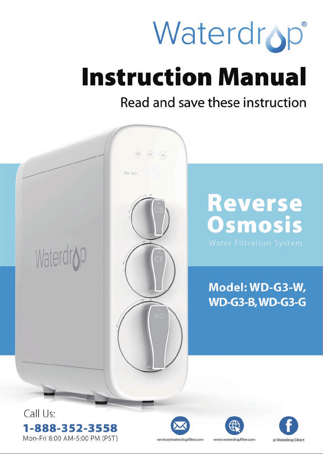
Tested and Certied by NSF International in Model WD-G3-W
against NSF/ANSI Standard 58 for the reduction of the claims
specied on the Performance Data Sheet, and to NSF/ANSI
372 (≤0.25% lead).
Find the installation video
Register 1-year manufacturer warranty*
* Please refer to Limited Product Warranty on Page 19
Search “Waterdrop G3 RO installation” on
Performance Data Sheet


Contents
Installation Instructions
Before Installation ···············································1
Parts List ·························································2
Product Introduction ·············································3
Installation Tips ···················································4
Installation Steps ················································5
Step 1: Install the Feed Water Adapter
·································5
Step 2: Install the RO Faucet
·········································6
Step 3: Install the Drain Saddle
······································7
Step 4: Position the RO System Housing
·······························7
Step 5: Connect Tubing
·············································8
Step 6: Connect Power Cord
············································9
Step 7: Install the Filters
·············································9
Step 8: Start up the System
·········································10
Owner’s Manual
Display and Operation ···········································12
Section 1: TDS Display
·············································12
Section 2: Filter Life Reminder
·······································12
Section 3: Filter Replacement Guide
··································14
Section 4: Automatic Flushing
······································15
Sect
ion 5: Malfunction Display
······································15
System Maintenance ···········································16
Troubleshooting ·················································17
Limited Product Warranty ·······································19
1
Installation Instructions
Before Installation
Inspect the Package
Open the box and take out the system housing, all the components and connect
ttings. Inspect them according to the parts list to ensure nothing is left out or
damaged during shipping. If there are any parts cracked or broken, please do not
proceed with the installation and contact Waterdrop by phone: 1-888-352-3558
Mon-Fri 8:00 AM-5:00 PM (PST) or by email: service@waterdroplter.com. Identify
and get familiar with all components for quick installation.
Specications
To achieve the optimal performance, it is highly recommended to use the system
within the operational parameters.
Model
RO System Size (L
*
W
*
H)
Feed Water Pressure
Feed Water Temperature
Daily Production Rate
Feed Water Requirement
Power Specication
WD-G3-W / WD-G3-B / WD-G3-G
18.06”
*
5.68”
*
17.76”
14.5-87 PSI / 0.1-0.6 MPa
41-100 °F / 5–38 °C
400 GPD
Municipal Tap Water
Input 110~120V AC
Output 24V DC
NOTE:
• The Daily Production Rate is measured under 30 PSI dynamic feed water
pressure and 77 °F water temperature.
Required Tools:
• Variable speed drill
• Drill bit: 1/4” (for the waste line), 1⅜” (for faucet hole)
• Adjustable wrench, pliers
• Screwdriver
• Utility knife or scissors
• Flashlight
• Towel
2
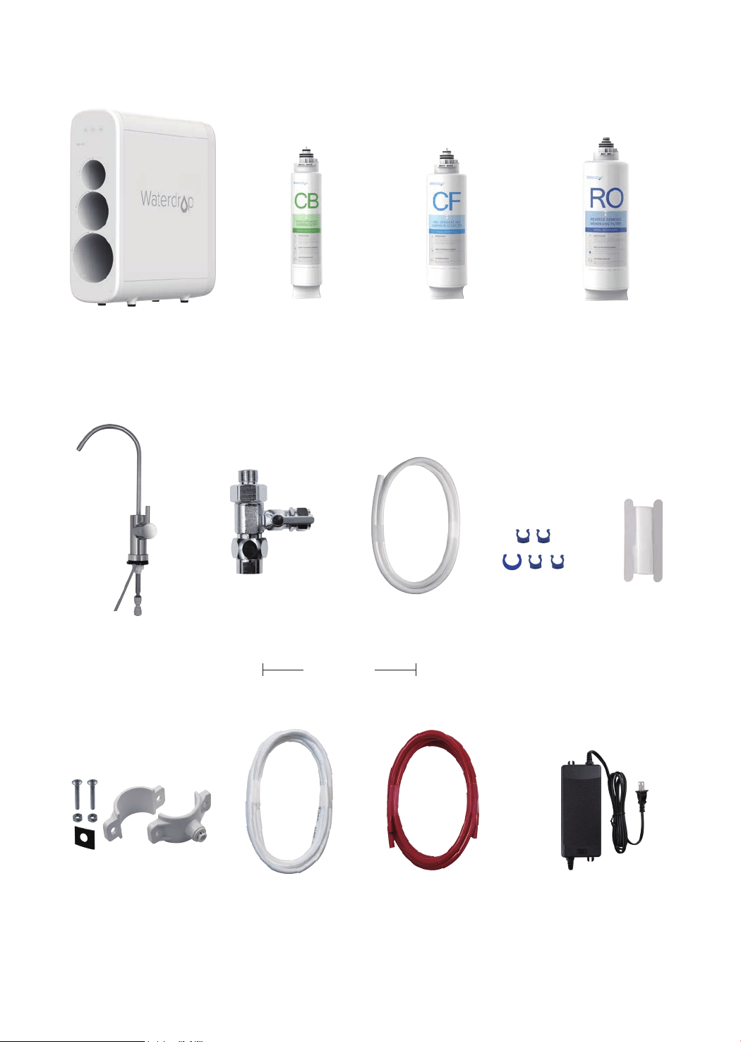
Parts List
System Housing
Feed Water Adapter
3/8”-1/2”
White 1/4” PE Tubing
RO Faucet
Power AdapterDrain Saddle 1/4”
Teon Tape
Red 1/4” PE Tubing
White 3/8” PE Tubing Lock Clip
X 1 Set
X 1 Set
X 1 Set
X 1 Set
X 1
X 1 Set
X 60” X 60”
X 60” X 5
Pre-sediment and
Carbon Block Filter
(CF: WD-G3-N1CF)
X 1
Reverse Osmosis
Membrane Filter
(RO: WD-G3-N2RO)
X 1
Activated Carbon Filter
(CB: WD-G3-N3CB)
X 1
Preinstalled
3
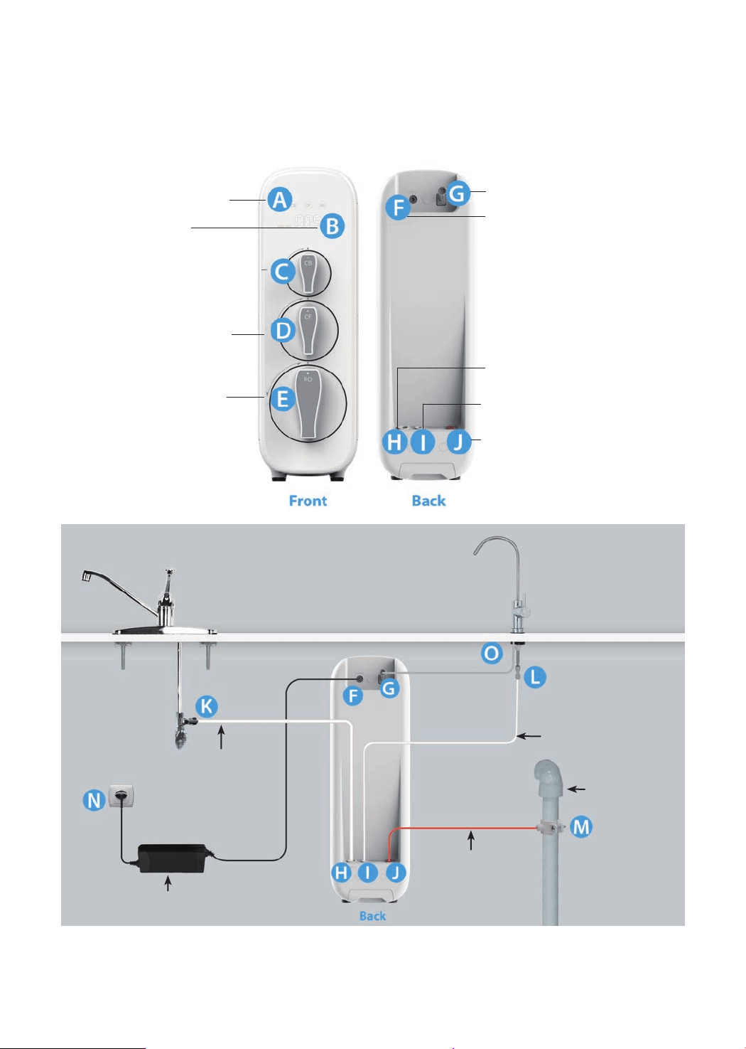
Product Introduction
The brief introduction of various parts and sample connections are presented as
follows. Please identify and get familiar with these parts and connection points for
a smooth installation.
K
→
H, From Feed Water Adapter to “INPUT” Water Port
L
→
I, From Faucet Quick-Connect Fitting to “FILTERED” Water Port
M
→
J, From Drain Saddle to “WASTE” Water Port
O
→
G, From Faucet Power Cord to “FAUCET” Connector
F
→
N, From “POWER” Port to Power Socket
H:
“INPUT” Water Port
I:
“FILTERED” Water Port
J:
“WASTE” Water Port
Filtered Water Tubing
1/4" PE Tube
Input Water Tubing
3/8"PE Tube
Waste Water Tubing
1/4" PE Tube
Drain Pipe
Power Adapter
A:
Filter Life Indicators
F:
“POWER” Port
G:
“FAUCET” Connector
B:
Display Screen
C:
Activated Carbon Filter
(CB)
D:
Pre-sediment and
Carbon Block Filter (CF)
E:
Reverse Osmosis
Membrane Filter (RO)
Sample Connection
4
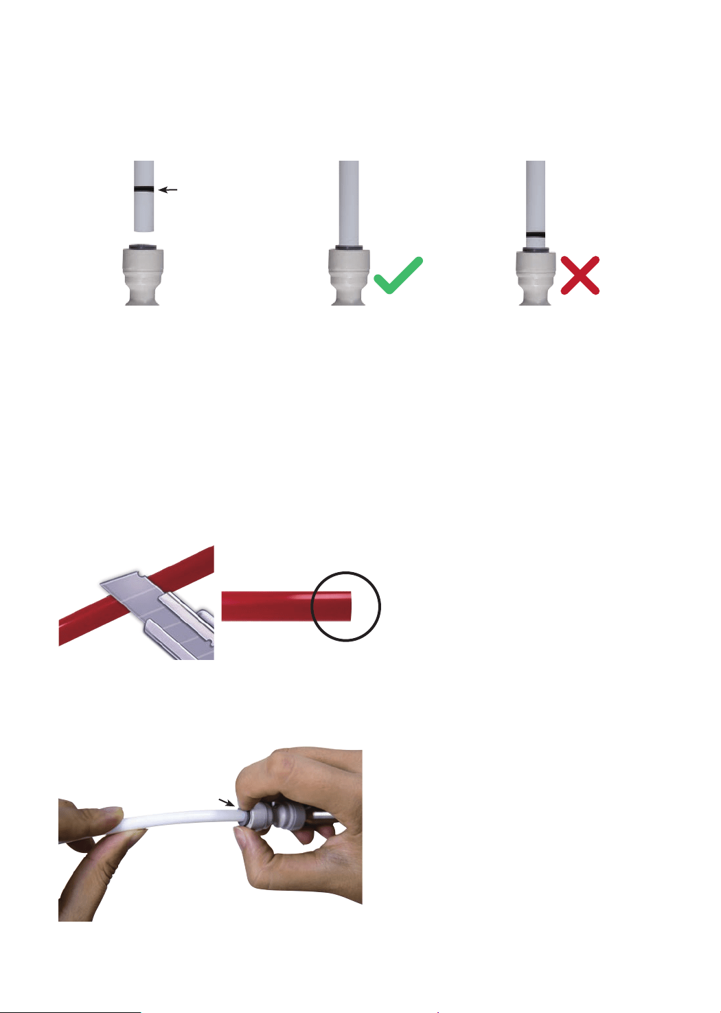
Installation Tips
How to Use the Quick-Connect Fittings
To connect:
NOTE: There is an existing mark (Figure 1) at the end of the tubing for you to
conrm if the tubing is fully inserted into the tting.
• Push the tubing into the tting until you reach the mark on the tubing.
NOTE: If the tubing is not fully inserted, no seal will be created and leakage will
occur.
• When the tubing is fully inserted, put the blue lock clip on the tting. It will lock
the tubing in place and prevent it from falling off.
To disconnect:
• Remove the blue lock clip from the
tting;
• Use your thumb and index nger
to press down the lock sleeve. Use
your other hand to pull out the tube
from the tting (Figure 3).
NOTE: Please do not pull out the
tubing directly. This will damage the
tting and cause leakage.
Figure 1
Figure 2
Figure 3
NOTE: If the tubing is too long,
cut it to a suitable length with a
sharp utility knife or scissors. Cut
the tubing squarely and cleanly
(Figure 2). Make sure the tubing
is fully inserted (about 0.8”).
Mark for
Full Insert
Press
Cut Cleanly
and Squarely

5
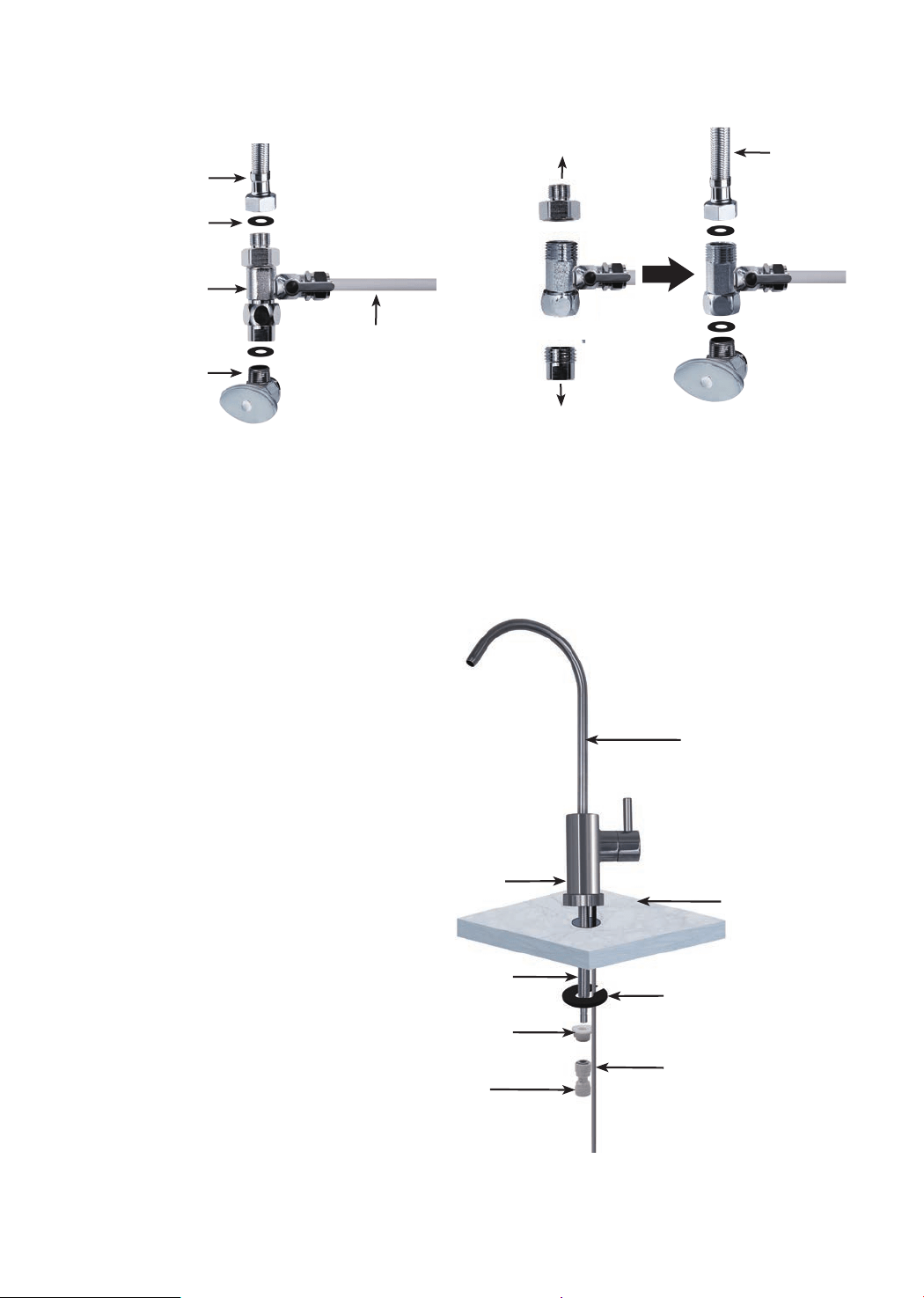
Step 1:
Install the Feed Water Adapter (3/8” or 1/2”)
NOTE: The “INPUT” water tubing has been attached to the feed water adapter for
easy installation.
1. Shut off the water supply. Turn on the kitchen faucet to release the water pressure;
NOTE: Make sure the water has stopped before proceeding to the next step. Get a
towel or bucket to catch any excess water.
2. Disconnect the cold water pipe from the cold water supply valve;
3. Twist the feed water adapter onto the cold water supply valve (with its washer) and
tighten it with an adjustable wrench (Figure 4);
NOTE: If the cold water pipe is 1/2”, unscrew the two converters from the feed
water adapter (Figure 5), and then implement step 3.
4. Twist the cold water pipe (with its washer) onto the feed water adapter and tighten
with an adjustable wrench.
Installation Steps
NOTE:
• The RO system must be connected to the COLD water supply ONLY.
• Do not install the system in exposure to direct sunlight or harmful chemicals, nor
any place where it may be damaged.
• Do not install the system near any heat source.
• Do not install the system outdoors.
How to Drill a Hole into Your Sink or Countertop (Optional)
NOTE: Please conrm if there is an existing hole available to install the RO faucet.
If not, please drill a hole in accordance with the following steps.
It’s highly recommended to watch the YouTube video “How to Drill Faucet Holes”
for a better understanding of the process. There is also a reference sticker to help
you drill the hole. Remember to wear safety glasses to protect your eyes while
drilling the faucet hole.
1. Choose a diamond core bit for granite, and a carbide drill bit for stainless steel.
Do not use a hammer drill on natural stone, glass or ceramic;
2. Glue the sticker on your sink or countertop, and drill a hole referring to the
sticker hole size (1⅜”);
3. Make an indent with a center punch on a stainless-steel sink before drilling to
help guide the bit;
4. Be careful when drilling on a porcelain sink, as it can be easily chipped. Apply
downward pressure rmly on the bit until you break through the surface;
5. Starting at the lowest speed, and hold the drill straight with rm pressure to
prevent the bit from walking on the counter;
6. Once you break through the surface, swirl the drill a little to apply pressure in a
circle evenly.
Prior to installation, it is highly recommended to watch the video “Waterdrop G3 RO
Installation” on YouTube.
6
Step 2:
Install the RO Faucet (Non-Air Gap Faucet)
NOTE: If your kitchen sink
or countertop does not
have an existing hole, you
will have to drill one (1⅜”).
Refer to Page 5.
1. Insert the faucet spout
into the faucet body;
2. Insert the faucet
stem and power cord
into the hole on the
countertop;
3. Under the sink, put the
mounting washer on
the faucet stem, slip
on the nut and tighten
it up;
4. Insert the quick-
connect tting onto the
faucet stem fully and
rmly.
Faucet Body
3/8"
Cold Water Pipe
1/2"
Cold Water Pipe
Washer
Unscrew
Unscrew
3/8" INPUT Water
Tubing
Feed Water
Adapter
Cold Water
Supply Valve
Mounting Washer
Nut
Faucet Stem
Countertop
Faucet Spout
Faucet Power Cord
Quick-Connect
Fitting
Figure 4 Figure 5
Figure 6
7
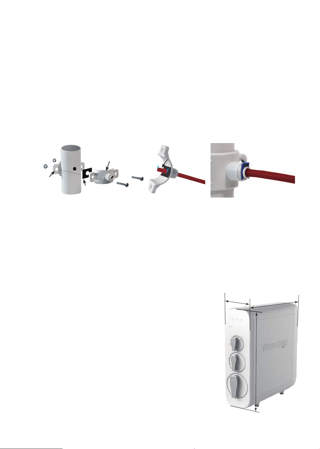
Step 3:
Install the Drain Saddle
1. Choose a spot on the drainpipe that is convenient for installing the drain saddle;
NOTE: It’s recommended to install the drain saddle on the vertical drainpipe.
2. Drill a 1/4” hole in the drainpipe. Be sure not to penetrate the opposite side of the
pipe;
3. Slip the front plate on one end of the tubing (without the mark), and insert the tubing
into the drilled hole for about 0.6” (Figure 8);
4. Position the back plate on the drainpipe by tightening the screws and nuts evenly
while leaving the tubing in the hole;
5. Pop the lock clip on the tting to secure the connection (Figure 9).
NOTE: In some cases, the “WASTE” water tubing needs to be connected to the
drainpipe through air gap. Consumers need to purchase air gap accessories additionally.
Figure 7 Figure 8 Figure 9
Foam Seal
Front Plate
About 0.6"
Back
Plate
Step 4:
Position the RO System Housing
Check and ensure there is sufcient space under the countertop to install the system
(18.06”
*
5.68”
*
17.76”). Position the front panel facing toward you, which will be
convenient for future lter replacement and indicator checking.
NOTE: It is not recommended to place the housing against the cabinet, as there may
be vibrations when the system works.
a) The power-supply receptacle for the appliance shall
be installed in a cabinet or on a wall adjacent to the
undercounter space in which the appliance is to be
installed;
b) There should be an opening through the partition
between the compartments specied in (a) that is large
enough for the attachment plug to pass through. The
longest dimension of the opening shall not be more than
1-1/2 in (38 mm);
c) If the partition is wood, the edges of the opening
specied in (b) should, be smooth and rounded. If the
partition is metal, it should be covered with an edge
protector provided for this purpose by the manufacturer;
d) Care should be exercised when the appliance is
installed or removed in order to reduce the likelihood of
damage to the supply cord.
17.76”
18.06”
5.68”
Figure 10
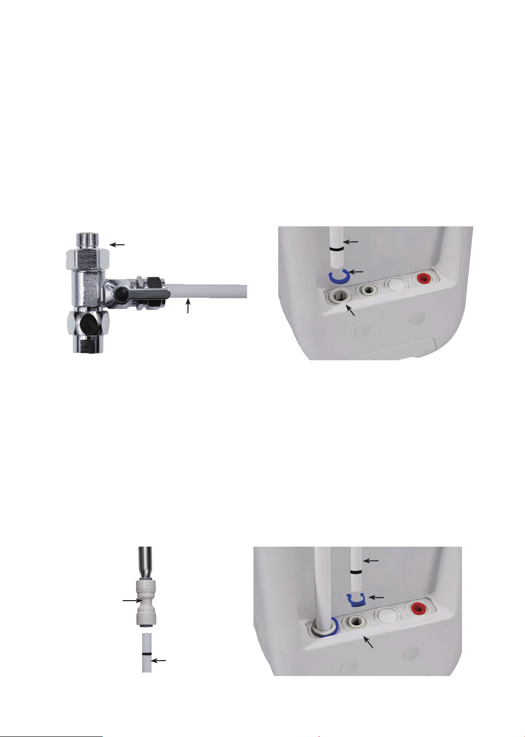
Step 5:
Connect Tubing
1. Install the “INPUT” Water Tubing
• Remove the plug from “INPUT” water port;
• Identify the white 3/8” PE tubing which has been attached to the feed water
adapter (Figure 11);
• Insert the other end of the tubing into the “INPUT” water port (Figure 12), and pop
the lock clip on the tting.
NOTE: Make sure it is fully inserted until you reach the mark on the tubing.
NOTE: Conrm the tubing length you need rst, and then cut the tubing if it’s too
long, referring to “How to Use the Quick-Connect Fittings” on page 4.
8
2. Install the “FILTERED” Water Tubing
• Remove the plug from the “FILTERED” water port;
• Identify the white 1/4” PE tubing;
• Insert one end of the PE tubing into the quick-connect tting on the RO faucet
(Figure 13), and pop in the lock clip on the tting;
NOTE: Make sure it is fully inserted until you reach the mark on the tubing.
• Insert the other end of the tubing into the “FILTERED” water port (Figure 14), and
pop the lock clip on the tting.
NOTE: Make sure it is fully inserted until you reach the mark on the tubing.
Quick-connect
Fitting on RO Faucet
“FILTERED”
Water Tubing
“INPUT” Water Port
“INPUT” Water
Tubing
Lock Clip
Lock Clip
“FILTERED” Water
Tubing
Feed Water Adapter
“INPUT” Water Tubing
Figure 11
Figure 13
Figure 12
Figure 14
“FILTERED” Water Port
9
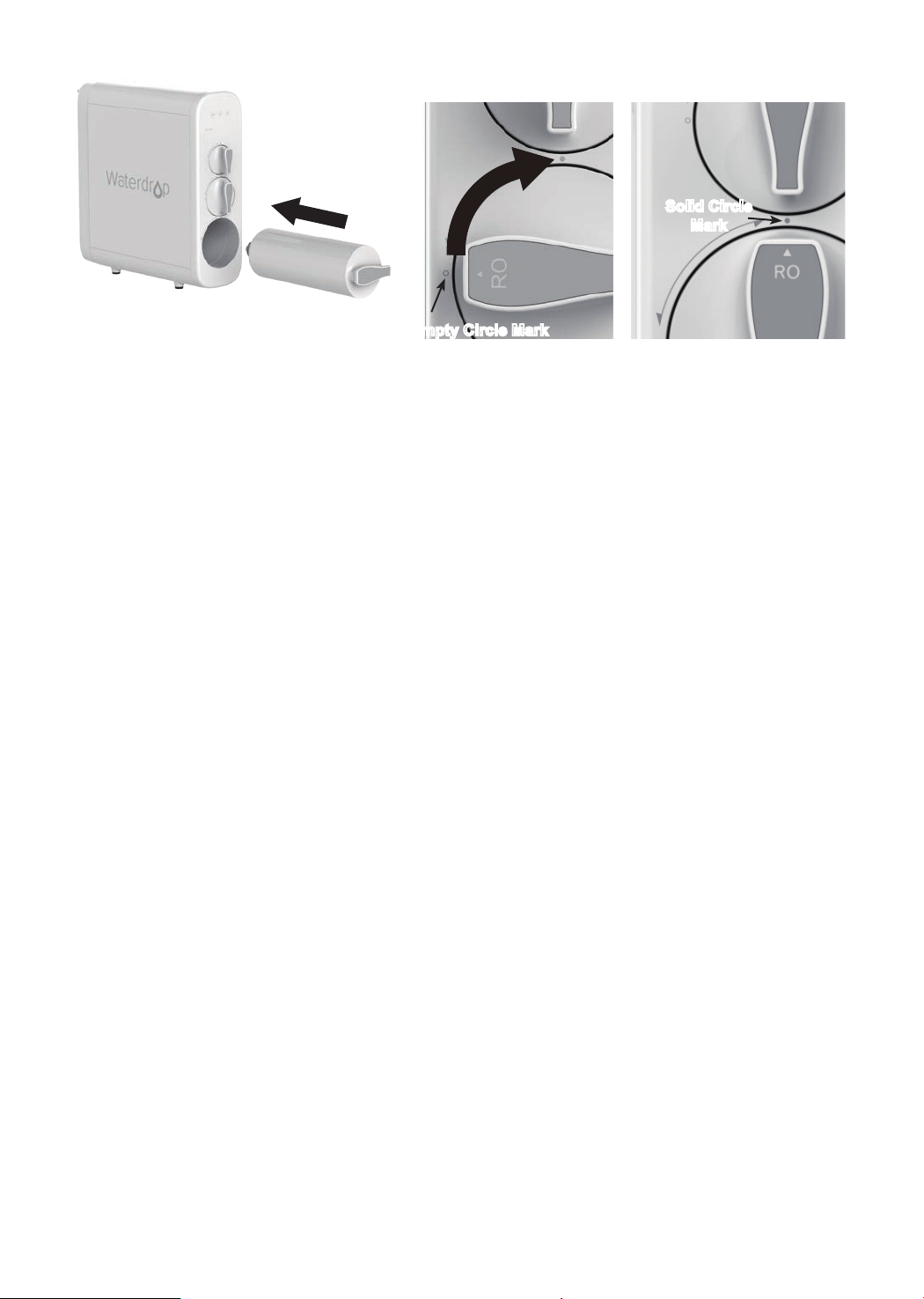
Step 7:
Install the Filters
Each lter is marked with a logo (CB/CF/RO) and an installation arrow.
1. Remove the wrapping and protective cap from the lter;
2. Insert the lter into its corresponding hole (Figure 19), align the arrow with the
empty circle on the housing (Figure 20);
3. Twist the lter with a little force forward in a clockwise direction for 90 degrees,
until the arrow is aligned with the solid circle on the housing (Figure 21). You
may hear a clicking sound when the lter is tted into place properly;
4. Repeat the above steps to install the other two lters.
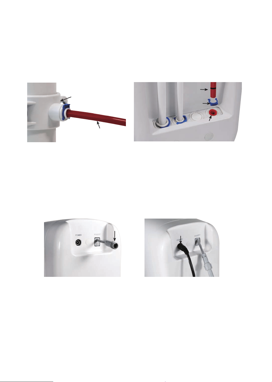
“FAUCET” Connector
“POWER” Port
Figure 17 Figure 18
Drain
Saddle
“WASTE”
Water Tubing
“WASTE”
Water Port
Lock Clip
“WASTE” Water
Tubing
Figure 15 Figure 16
Step 6:
Connect Power Cord
Connect the RO faucet to with the system: Insert the power cord which is attached
to the RO faucet into the “FAUCET” connector (Figure 17) at the back of the
housing, and tighten the nut.
Connect Power Adapter: Insert the DC head of the power adapter into the “POWER”
port at the back of the housing (Figure 18).
NOTE: Please do not connect power socket now.
3. Install the “WASTE” Water Tubing
• Remove the plug from the “WASTE” water port;
• Identify the red 1/4” PE tubing which has been attached to the drain saddle (Figure
15);
• Insert the other end of the tubing into the “WASTE” water port (Figure 16), and
pop the lock clip onto the tting.
NOTE: Make sure it is fully inserted until you reach the mark on the tubing.
10
Figure 19 Figure 20 Figure 21
Solid Circle
Mark
Empty Circle Mark
Step 8:
Start up the System
1. Turn on the cold water supply valve. Check for leaks;
2. Insert the plug of power adapter into the socket;
NOTE: If the system can’t be powered on after you insert the plug of power
adapter, check the power under the sink, as this mostly occurs when the power
under the sink is powered off. Also, check the connection between the plug and
the power outlet, and ensure that the system has been plugged correctly into
the power outlet, as this may occur in a few cases. To test if there is a problem
with the system itself, just pick up the system and try another power outlet.
Please contact us if the system can’t be powered on. We will help you gure it
out.
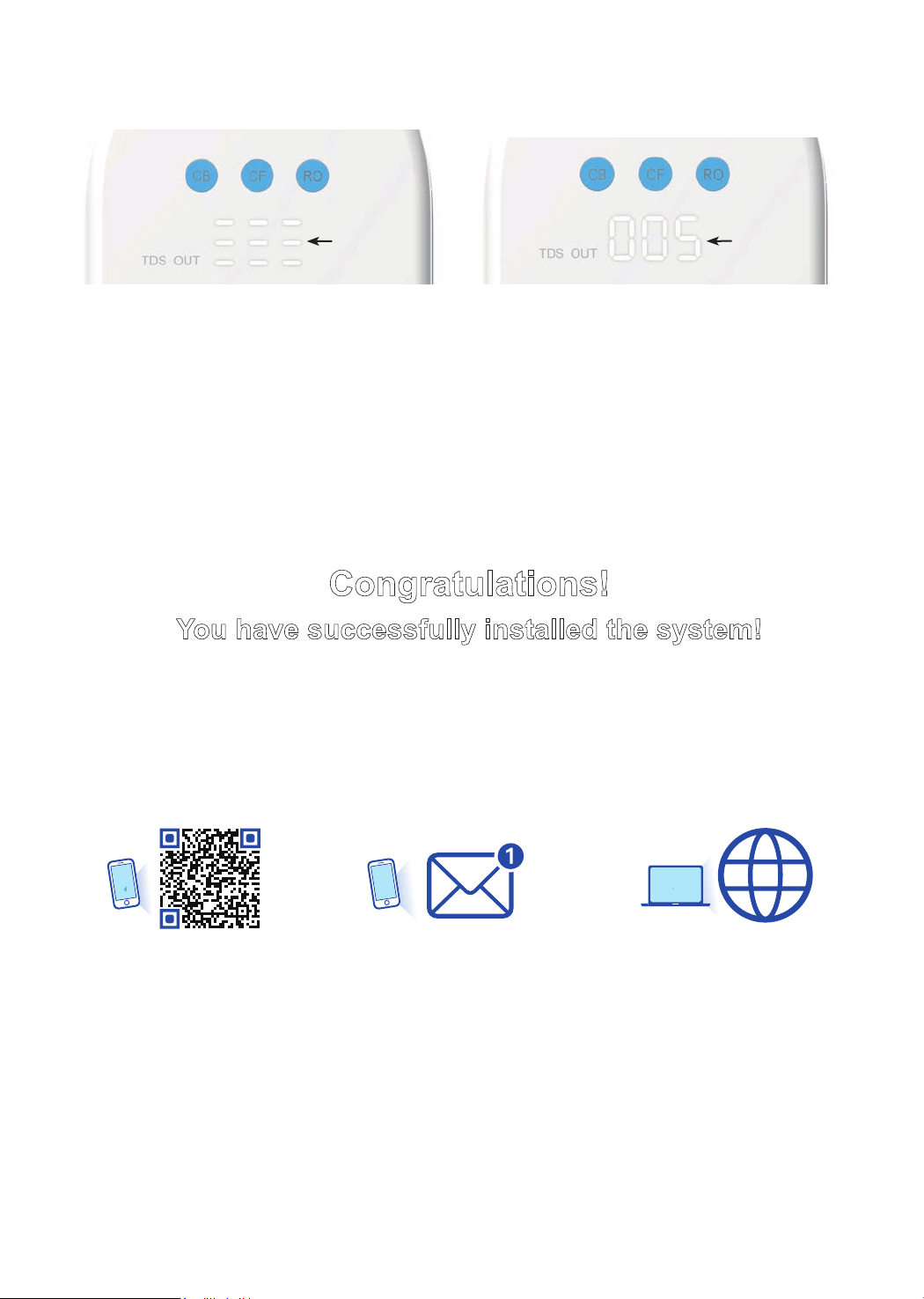
3. The system starts ushing automatically for 5 minutes;
NOTE: There will be one beep. The lter life indicators will ash blue, yellow
and red in turn and then turn blue for 5 minutes (Figure 22). Do not turn on the
RO faucet. Allow the system to ush automatically for 5 minutes. The three
indicator lights will be off when the ush is complete.
NOTE: A slow water ow is normal if the RO faucet is turned on, and water is
not drinkable during the automatic ush.
4. Turn on the RO faucet, and allow it to run for 30 minutes until the front panel
screen starts displaying a TDS reading (Figure 23);
NOTE: Be sure to carefully check the tightness of each part of the system while
ushing. Check and ensure all tubing is installed correctly and completely. Make
sure there are no leaks at the joints, ttings, valves and tubing connections.
NOTE: The water is not drinkable during the ushing. The 30 minutes are
accumulative. If the ush is stopped in advance, the system will continue to
ush when you open the RO faucet again until it reaches 30 minutes.
5. Conrm the ush is completed before turning off the RO faucet and ensure it’s
not leaking.
11
Congratulations!
You have successfully installed the system!
Register your product now for
1 YEAR MANUFACTURER WARRANTY*
* Please note that the reading in the gure is only used as an example, and the actual reading may vary
according to different water conditions.
Visit
Scan the QR code or Text
WDRO to 31996 or
Figure 22 Figure 23
TDS Reading
Flushing
Status
warranty.waterdroplter.com
12
Owner’s Manual
Display and Operation
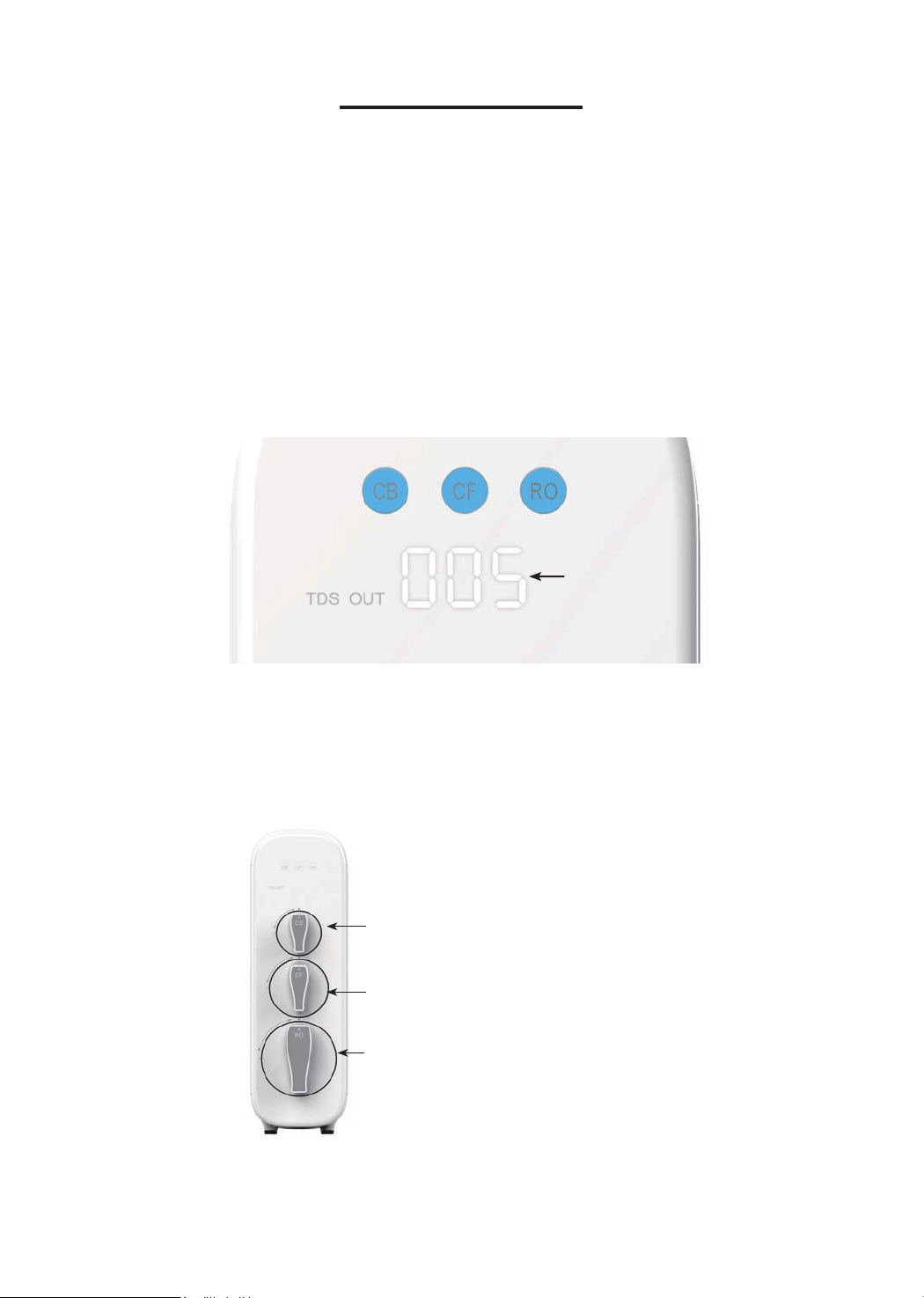
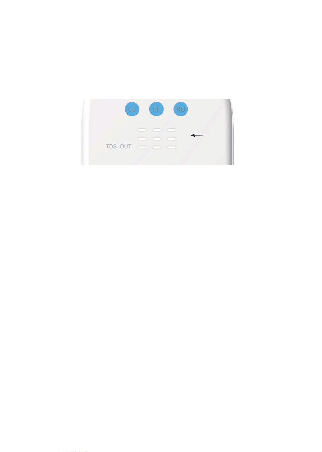
Section 1: TDS Display
The built-in TDS sensor detects the water quality when the system begins to work,
and shows the TDS reading on the front panel display screen (Figure 25).
NOTE:
The system will provide above a 90% TDS rejection rate when working properly,
which may vary with a deviation of 10% depending on the source water quality and
water usage. The TDS reading may vary as the water is owing.
The TDS display will go off after 5 minutes when the system stops making water.
Section 2: Filter Life Reminder
Figure 25
TDS Reading
Pre-sediment and Carbon Block Filter (CF)
Reverse Osmosis Membrane Filter (RO)
Activated Carbon Filter (CB)
Filter Life: 6 months or 550 gallons
Filter Life: 24 months or 2,200 gallons
Filter Life: 12 months or 1,100 gallons
NOTE: Filter life may vary depending on source water quality and water usage.
Please replace the lter according to the reminder of the lter life indicators.
* Please note that the reading in the gure is only used as an example, and the actual reading may vary
according to different water conditions.
13
Display Status:
Status
Status
Replace Soon
Replace Now
Good
Normal
Pre-warning
Warning
≤15
≤ 0
≤40
≤ 0
>15 >40 Blue
Yellow
Red
N/A
Beeps 2 times when
dispensing water
Keeps beeping when
dispensing water
Indication
Light Buzzer
Remaining
Life (Day)
Remaining Capacity (G)
NOTE: The indicators will notify you according to the usage time or processing
capacity of the lters, whichever comes rst.
Display Time:
• All indicators will go off after 5 minutes when the system stops making water.
• Check the lter life status by touching the indicators, and the lights will go off in
30 seconds.
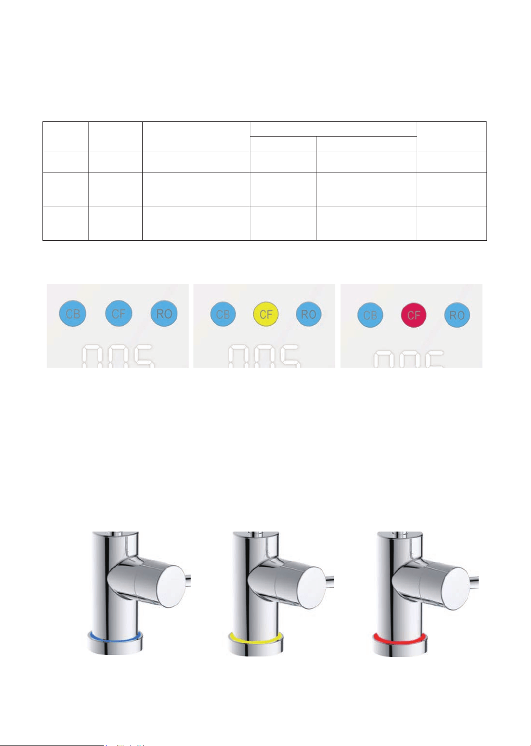
1. Filter Life Indicator on System Housing
There are helpful electronic lter indicators (CF/CB/RO) on the front panel (Figure
26) that will notify you to perform a routine lter replacement by color change. Be
sure to reset the lter life indicator every time you replace your lter.
2. Filter Life Indicator on the RO Faucet
Different light colors will be displayed on the RO faucet corresponding to the lter
life status (Figure 27).
Figure 26
Good Replace Soon Replace Now
Blue Yellow Red
Figure 27
14
NOTE: If the lter expires, please purchase and replace the lter immediately.
Otherwise, the ltration efciency will decrease signicantly and affect the
performance.
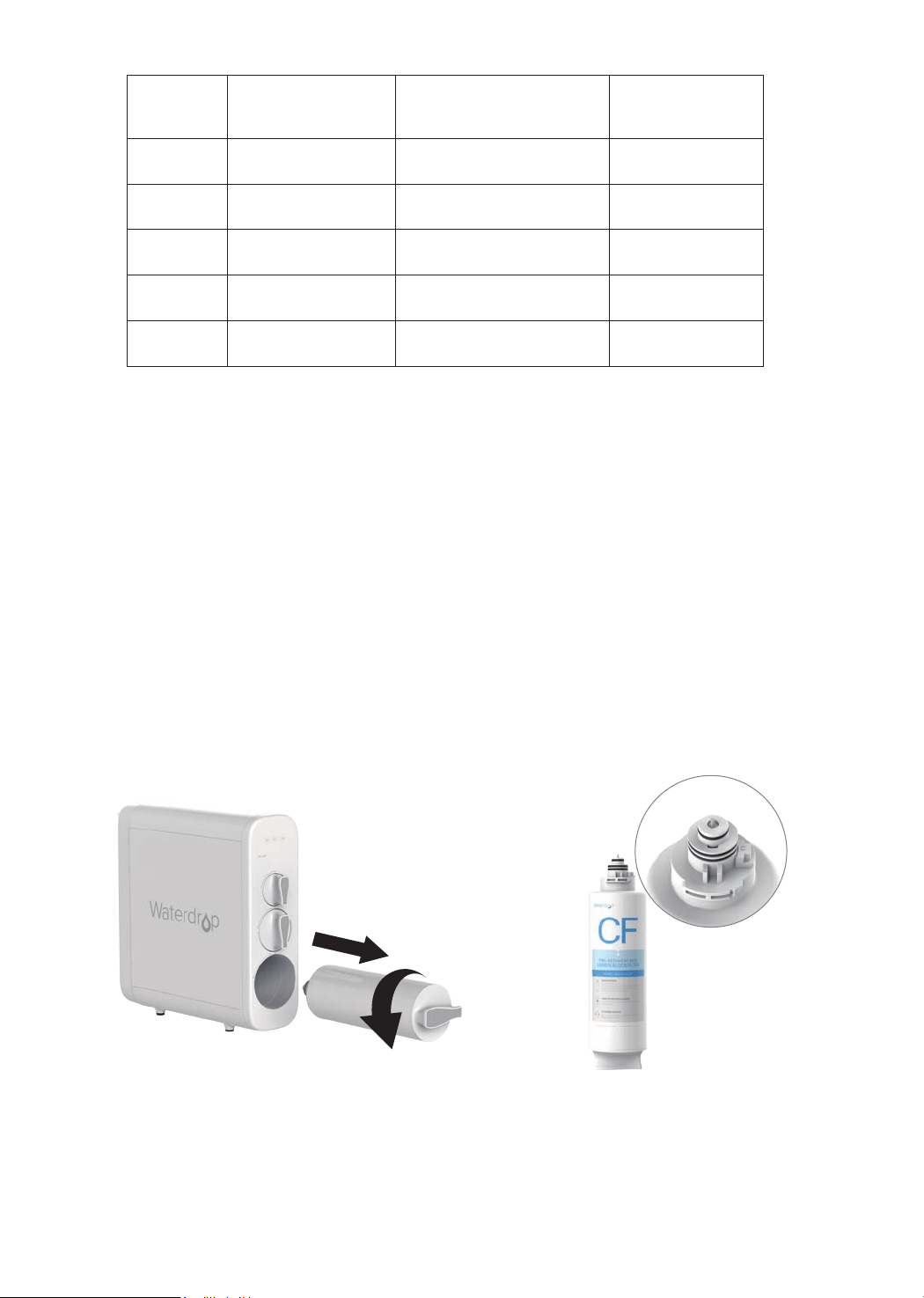
Section 3: Filter Replacement Guide
How to Replace Filters:
The lters could be replaced directly without cutting off the power and water
supplies, and there will be no water and electric leakage.
1. Twist off the lter that needs to be replaced in a counterclockwise direction (Figure
28).
NOTE: After replacing the CF and CB lter, it’s recommended to press the
center knob (Figure 29) protruding at the top of the old lter to release the
pressure to avoid water spills. Get a towel or bucket to catch any excess water;
2. Twist the new lter into the housing in a clockwise direction;
3. Reset the lter life indicator and ush the lter after replacement (please refer
to the following steps).
How to Reset the Filter Life Indicator (Taking Reset of CB Filter
Life Indicator as an Example):
Press and hold the CB lter life indicator for 7 seconds until the system beeps.
NOTE: The lter life reset of CF and RO is the same as the reset of CB.
Figure 28
Figure 29
Status
Blue
Blue Flash
Red Flash
Yellow
Red
≤15
≤ 0
/
/
/
/
≤40
≤ 0
>15 >40
Good
Replace Soon
Replace Now
Flushing
Malfunction
Light
Remaining Life (Day)
Remaining Capacity (G)
15
How to Flush the Filter after Replacement:
NOTE: The display screen will show the ushing status (Figure 30) during the
process.
For CF lter: It will be ushed automatically for 5 minutes without turning on the
RO faucet;
For CB lter: Turn on the RO faucet to ush for 15 minutes;
For RO membrane lter: Turn on the RO faucet to ush for 30 minutes.
Figure 30
Flushing Status
Section 4: Automatic Flushing
The system will be automatically ushed under the following circumstances:
Flush for Accumulative Working Time over 2 Hours:
To maintain and extend the life expectancy of the lters, the system will be
automatically ushed for 20 seconds when it accumulatively works up to 2 hours,
where the front panel screen will show a display as in Figure 30. If the user takes
water during the ushing, the system will quit ushing and switch to dispensing.
Flush for No Working within 24 Hours (Holiday Mode):
To ensure fresh and healthy drinking water, the system will be automatically
ushed for 1 minute when there is no water dispensing for 24 hours.The front panel
screen will display as seen in Figure 30. If the user takes water during ushing, the
system will quit ushing and switch to dispensing.
Flush for Power Restore
When power is restored from a blackout, the system will be forced to ush
automatically for 20 seconds, and the front panel screen will display as seen in
Figure 30. The blue, yellow and red lights will ash in turn for one second, and then
the blue light will be on for 20 seconds. The indicators will be off when the ushing
is complete.
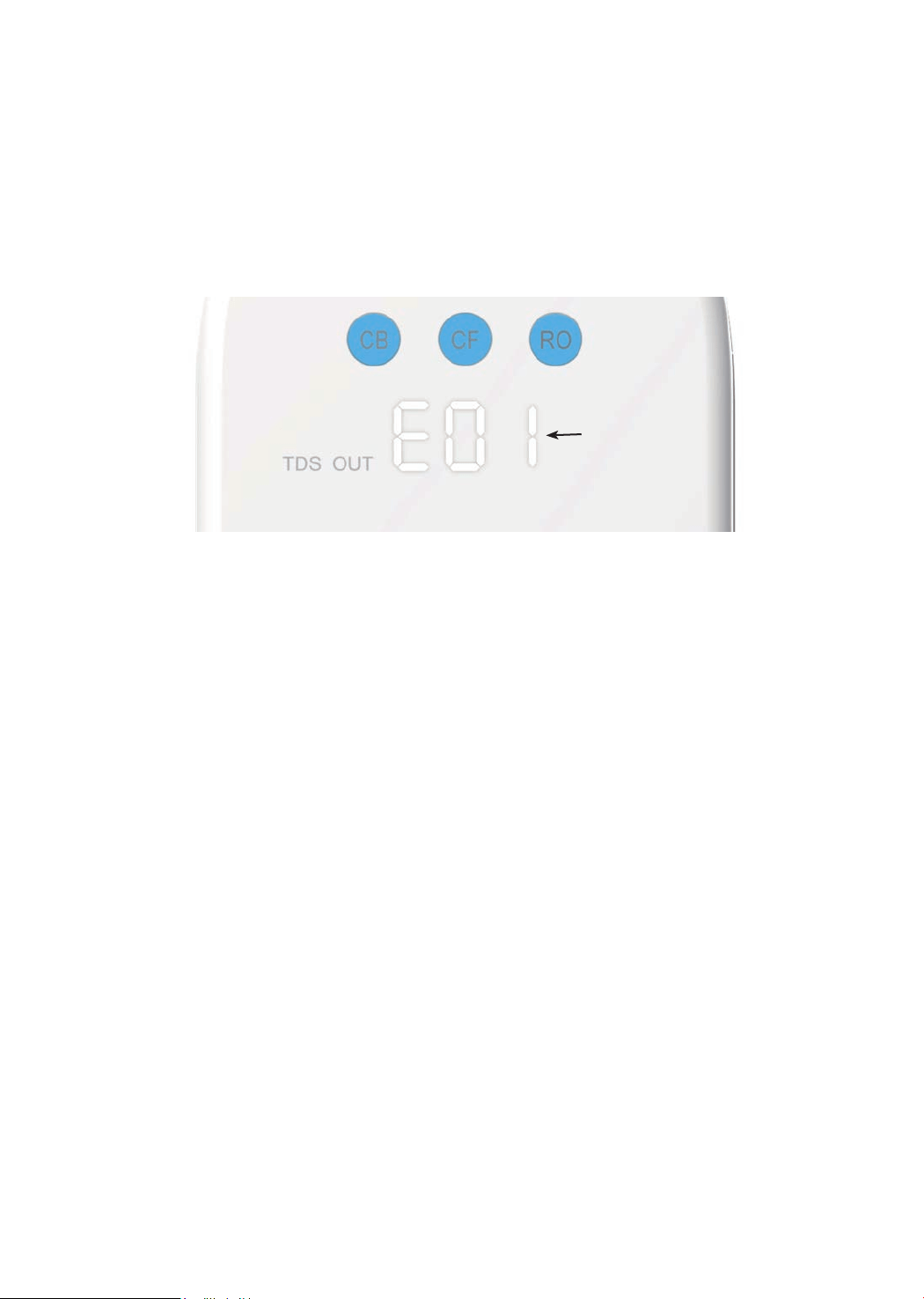
Section 5: Malfunction Display
When the system is in fault, the malfunction indicates as follows:
• E01: For water shortage, the buzzer sounds 3 times. When the inlet water
pressure returns to normal and the water shortage reminder disappears, the
system will automatically return to normal;
• E02: For inside water leakage, the buzzer keeps beeping;
• NOTE: Please pull out the water container at the back and check if there's any
water. If there is, clean the container and re-install it back. The malfunction
should be xed automatically. If E02 shows again shortly, please contact the
16
• If you don’t use the system for more than one week, turn on the RO faucet, shut
off the cold water valve, and disconnect the power. Seal the lters and store it in
the refrigerator (not the freezer). You need to open the RO faucet and allow it to
run for 10 minutes rst before using the system again. Otherwise, you need to
replace the lters, as bacteria may grow when the system is not used for a long
time.
• Please replace the lter regularly according to the lter life indicator.
• NOTE: While the testing was performed under standard laboratory conditions,
actual performance may vary depending on the source water quality and water
usage. In case of premature blockage and failure of the lters, it’s recommended
to replace the lter in accordance with the actual usage.
• Clean the system with clear water. Do not spray the water directly. Do not use
steel wool, an abrasive cleaner or corrosive liquid such as gasoline or acetone.
• When cleaning, do not pour other liquids into the lter to avoid damage to the
lter system.
• Keep the waste water pipe unobstructed to avoid damage to the lter or internal
components.
• When the drainpipe is blocked, do not use the system (please turn off the
power) to avoid waste water from soaking the oor.
• Check the system and water pipe ttings regularly for water leakage to avoid
any property damage.
• Regularly check whether the power supply and wires are damaged or loose to
avoid major accidents caused by electric leakage.
System Maintenance
Figure 31
Malfunction
Code
customer service hotline 1-888-352-3558 Mon-Fri 8:00 AM-5:00 PM (PST) for
assistance.
• E03: If the booster pump overworked, the buzzer beeps for 3 minutes. The
system will need to be powered on again to recover;
• E04: If the booster pump starts and stops frequently, the buzzer sounds 5
times. The system will need to be powered on again to recover.
NOTE: Please refer to “Troubleshooting” for detailed solutions concerning
malfunction code reminders.

17
• No Output Water from RO Faucet
a. Filter expired. Check the lter life indicators to conrm which lter needs to be
replaced and replace it immediately.
b. Low water pressure. Check and conrm the water pressure is between 14.5 PSI
and 87 PSI.
c. Water supply is off. Turn on the feed water adapter or water supply valve.
d. Incorrect lter installation. Reinstall the three lters, and make sure they are
tted properly.
e. A tubing is crimped. Check all tubing and remove any crimps.
• Low Water Flow at the RO Faucet
a. Leak from tubing connection. Check and ensure all tubing is installed correctly
and completely.
b. Filter expires. Check the lter life indicators to conrm which lter needs to be
replaced and replace it immediately.
c. Low water temperature. Be sure to use the system at a temperature of 41-100
°F
.
•If the System Cannot Be Powered on After You Insert the Plug
of Power Adapter
a. Check the power under the sink, as this mostly occurs when the power under
the sink is powered off. Also, check the connection between the plug and the
power outlet, and ensure that the system has been plugged correctly into the
power outlet, as this may occur in a few cases. To test if there is a problem with
the system itself, just pick up the system and try another power outlet. Please
contact us if the system can’t be powered on. We will help you gure it out.
• No Display on the System
a. To save power, the screen display and indicators will go off after 5 minutes
when the system stops making water, which is normal in this case.
b. No power or power adapter is broken. Check and make sure the power adapter
is plugged in. Change a new power adapter if it is broken.
Troubleshooting
• Water Leakage
a. Check all joints, ttings and tubing connections to locate the leakage. Make
sure the lters are well installed.
b. If the front panel screen shows the code E02, which means there is water
leakage inside the system, please pull out the water container at the back and
check if there’s any water. If there is, clean the container and re-install it. The
malfunction should be xed automatically. If E02 shows again shortly, please
contact the customer service hotline 1-888- 352-3558 Mon-Fri 8:00 AM-5:00
PM(PST) for assistance.

18
•Water Shortage Reminder
The front panel screen shows code E01 and the buzzer sounds 3 times.
a. Check if it is out of water. Turn on the feed water adapter or the water supply
valve.
b. The inlet water tubing is crimped. Check and remove crimps.
• TDS Reading Fluctuates When Dispensing Water
a. The TDS reading displayed is the TDS of the owing ltered water. Therefore,
the content of the dissolved solids may vary slightly as the water ows, causing
the uctuation of the TDS reading.
b. The built-in TDS sensor has deviation, causing the uctuation of the TDS
reading.
• The Difference between the TDS Reading Tested by the TDS
Meter and the Displayed Reading
a. The reading tested by the TDS Meter is the TDS of static water in the container
while the TDS reading displayed by the system is the TDS of owing water. As
a result, the TDS readings are different.
b. There are errors in the TDS Meter tests.
•Filtered Water from the RO Faucet Tastes Like Tap Water
a. Incorrect tubing installation. Make sure the waste water tubing is not connected
with RO faucet.
b. The lters are not well-installed. Make sure the lters are placed properly.
c. Filter expires. Check the lter life indicators to conrm which lter needs to be
replaced and replace immediately.
•High TDS in Filtered Water
The system will provide a 90%+ TDS rejection rate (tested under standard
laboratory conditions) when working properly. If the TDS reading is high, the
following causes are possible:
a. The system hasn’t been used for a long time. Open the RO faucet, allow it to
run for a while. The TDS reading will return to normal.
b. The RO membrane lter expired. Replace the RO membrane lter immediately.
c. The waste water pipe may be crimped or clogged. Check and remove crimps.
Re-align the drain saddle and drainpipe.
d. The source water may have a high TDS. Test the source water and ltered
water. The ltered water’s TDS shall be about 5%-10% of your source water’s
TDS. This is a normal range. If there is a high TDS in the source water, it may
reduce the service life of the system. When the ltered water’s TDS creeps
up to 15%-20% of the source water’s TDS, please perform routine lter
replacement.

•Booster Pump Starting and Stopping Frequently Reminder
The front panel screen shows code E04. The buzzer sounds 5 times.
There is an internal pressure imbalance. Disconnect the power. Turn on or turn off
the RO faucet completely and remove all tubing crimps. Make sure the faucet is
not blocked and power on the system again.
•Loud Sound of RO System
The sound will not exceed 65 DB, which makes no difference to everyday lives (65
DB is tested under standard laboratory conditions, where the feed water pressure
is between 14.5 PSI and 87 PSI). A loud sound may be caused by the following
reasons:
a. The system is not positioned in a at area. Make sure the system is placed
smoothly without shaking.
b. The system is placed against the cabinet. Do not place the system against the
cabinet. The system may vibrate when it works.
c. The water pressure is unstable. Check and conrm the water pressure is
between 14.5 PSI and 87 PSI. The sound will decrease when the water
pressure becomes stable.
•Booster Pump Overworked Reminder
The front panel screen shows code E03. The buzzer keeps beeping for 3 minutes.
a. Continuously dispensing water for more than 30 minutes. Power on the system
again to recover.
b. There is a leak at the tubing connection between the system and the RO
faucet. Turn off the power. Check the tubing connection, make sure the tubing
is inserted into the quick-connect tting properly and rmly, and power on the
system again.
19

20
Limited Product Warranty
The warranty of our product covers defects in materials and workmanship from
the original date of purchase. During the warranty period, we will replace or repair
any part deemed defective, as long as the product has not been subjected to
tampering, alteration, lack of regular maintenance or improper use after delivery.
The cost of repair or replacement under those excluded circumstances shall be
borne by the consumer. This limited warranty does not cover the following items:
lters and all other parts or components that require regular replacement as a
result of ordinary usage. This limited warranty only applies if the system is installed,
used, and maintained in compliance with all instructions and requirements
enclosed with the system.
This limited warranty shall only be valid if:
1. The system is to be used with municipal water only;
2. The feed water pressure is no less than 14.5 PSI and no longer than 87 PSI;
3. The feed water temperature must be no less than 41
°F
and no more than 100
°F
;
4. The feed water must have a pH between 6.5 and 8.5;
5. Turbidity must be less than 1.0 NTU.
Any information or suggestion with respect to our product concerning applications,
specications or standards is provided solely for your convenient reference. The
quality of water supplies may vary seasonably or over a period of time. Your
water usage may vary as well. The manufacturer assumes no liability for the
determination of the proper equipment necessary to meet your requirements, and
we do not authorize others to assume such obligation on our behalf. You must
verify and test the suitability of any information with respect to the product for your
specic application.
This limited warranty shall be void if:
1. The cartridge lters are not replaced on the recommended maintenance
schedule;
2. The product is purchased from someone other than our ofcial website or our
authorized dealers, as we cannot verify or guarantee the integrity or authenticity
of the Product.
Our sole obligation under this warranty shall be repair or replacement of a non-
conforming product or parts of this product, or at our option, return of the product
and a refund of the purchase price. Our obligation does not include the cost of
transportation. We are not responsible for damage in transit, and claims for such
damage should be presented to the carrier by the customer.
The warranties set forth herein are the only warranties made by us with respect to the
product. We make no warranties, expressed or implied, including, but not limited to, any
warranties of tness or merchantability, except as expressly set forth above.

21
NOTE: In case some states do not allow limitations on how long an implied
warranty lasts, you may choose to return the system. If you choose to keep
it, you agree that the above limitations still apply to you.
Warranty Registration
Please visit our website www.waterdroplter.com and go to the “Warranty
Registration” tab to register your product for the warranty.
We offer a 30-day money back guarantee, a 1-year manufacturer warranty,
and lifetime tech support for all our products. Please be sure to ll in the order
information upon registration of your system. For any questions and concerns
about the product, please feel free to call or email us. Your satisfaction is our top
priority!
If you are happy with our products and service, please share with your friends or
share on Amazon. We highly appreciate your voice and support. Thank you!
How to Contact Us
Tel: 1-888-352-3558 Mon-Fri 8:00 AM-5:00 PM (PST)
Email: service@watedroplter.com
HongKong Ecoaqua Co., Limited.
Made in China