Loading ...
Loading ...
Loading ...
MAINTENANCE INSTRUCTIONS .............................
TRACTION DRIVE BELT SERVICE ...................
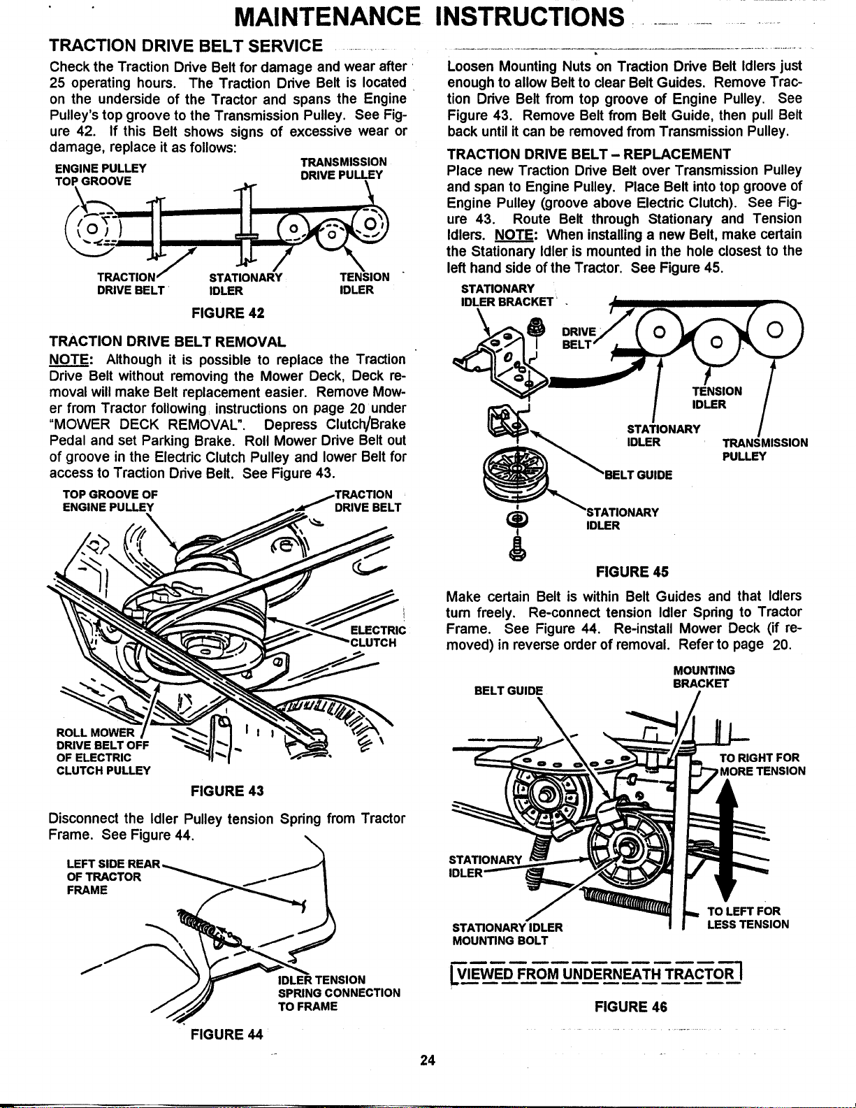
Check the Traction Drive Belt for damage and wear after
25 operating hours. The Traction Drive Belt is located
on the underside of the Tractor and spans the Engine
Pulley's top groove to the Transmission Pulley. See Fig-
ure 42. If this Belt shows signs of excessive wear or
damage, replace it as follows:
ENGINE PULLEY TRANSMISSION
TOP GROOVE DRIVE PULLEY
__lll__/ STATIONARY TENSION
DRIVE BELT IDLER IDLER
FIGURE 42
TRACTION DRIVE BELT REMOVAL
NOTE: Although it is possible to replace the Traction
Drive Belt without removing the Mower Deck, Deck re-
moval will make Belt replacement easier. Remove Mow-
er from Tractor following: instructions on page 20 under
"MOWER DECK REMOVAL". Depress Clutch/Brake
Pedal and set Parking Brake. Roll Mower Drive Belt out
of groove in the Electric Clutch Pulley and lower Belt for
access to Traction Drive Belt. See Figure 43.
TOP GROOVE OF
ENGINE PULLEY DRIVE BELT
Loosen Mounting Nuts on Traction Drive Belt Idlers just
enough to allow Belt to clear Belt Guides. Remove Trac-
tion Drive Belt from top groove of Engine Pulley. See
Figure 43. Remove Belt from Belt Guide, then pull Belt
back until it can be removed from Transmission Pulley.
TRACTION DRIVE BELT- REPLACEMENT
Place new Traction Drive Belt over Transmission Pulley
and span to Engine Pulley. Place Belt into top groove of
Engine Pulley (groove above Electric Clutch). See Fig-
ure 43. Route Belt through Stationary and Tension
Idlers. NOTE: When installing a new Belt, make certain
the Stationary Idler is mounted in the hole closest to the
left hand side of the Tractor. See Figure 45.
STATIONARY
IDLER BRACKET _ . /| ,, -.
j_/ll BELT" _ _ _ I._ /
STATIONARY I
IDLER TRANSMISSION
PULLEY
BELT GUIDE
(_ IDLER
I
ELECTRIC
CLUTCH
ROLL MOWER
DRIVE BELT OFF
OF ELECTRIC
CLUTCH PULLEY
FIGURE 43
Disconnect the Idler Pulley tension Spring from Tractor
Frame. See Figure 44.
OF TRACTOR
FRAME
FIGURE 44
IDLER TENSION
SPRING CONNECTION
TO FRAME
FIGURE 45
Make certain Belt is within Belt Guides and that Idlers
turn freely. Re-connect tension Idler Spring to Tractor
Frame. See Figure 44. Re-install Mower Deck (if re-
moved) in reverse order of removal. Refer to page 20.
MOUNTING
BRACKET
BELT GUIDE /
1 1 _ _ HT FOR
MOUNTING BOLT
LVIEWED FROM UNDERNEATH TRACTOR ]
FIGURE 46
24
Loading ...
Loading ...
Loading ...