Loading ...
Loading ...
Loading ...
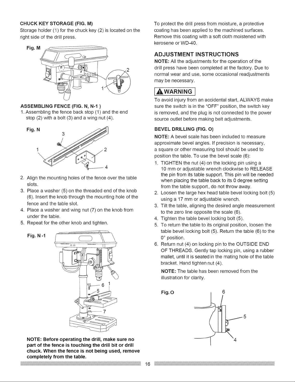
CHUCKKEYSTORAGE(FIG.M)
Storage holder (1) for the chuck key (2) is located on the
right side of the drill press,
Fig. M
ASSEMBLING FENCE (FIG. N, N-1 )
1. Assembling the fence back stop (1) and the end
stop (2) with a bolt (3) and a wing nut (4).
To protect the drill press from moisture, a protective
coating has been applied to the machined surfaces.
Remove this coating with a soft cloth moistened with
kerosene or WD-40.
ADJUSTMENT INSTRUCTIONS
NOTE: All the adjustments for the operation of the
drill press have been completed at the factory. Due to
normal wear and use, some occasional readjustments
may be necessary.
,,AWARNING
To avoid injury from an accidental start, ALWAYS make
sure the switch is in the "OFF" position, the switch key
is removed, and the plug is not connected to the power
source outlet before making belt adjustments.
Fig. N
3
2
4
2. Align the mounting holes of the fence over the table
slots.
3. Place a washer (5) on the threaded end of the knob
(6). Insert the knob through the mounting hole of the
fence and the table slot.
4. Place a washer and wing nut (7) on the knob from
under the table.
5. Repeat for the other knob and tighten.
Fig. N-1
BEVEL DRILLING (FIG. O)
NOTE: A bevel scale has been included to measure
approximate bevel angles. If precision is necessary,
a square or other measuring tool should be used to
position the table. To use the bevel scale (6):
1. TIGHTEN the nut (4) on the locking pin using a
10 mm or adjustable wrench clockwise to RELEASE
the pin from its table support. This pin will be needed
when placing the table back to its 0 degree setting
from the table support, do not throw away.
2. Loosen the large hex head table bevel locking bolt (5)
using a 17 mm or adjustable wrench.
3. Tilt the table, aligning the desired angle measurement
to the zero line opposite the scale (6).
4. Tighten the table bevel locking bolt (5).
5. To return the table to its original position, loosen the
table bevel locking bolt (5). Return the table (6) to the
0° position.
6. Return nut (4) on locking pin to the OUTSIDE END
OF THREADS. Gently tap locking pin, using a rubber
mallet, until it is seated in the mating hole of the table
bracket. Hand tighten nut (4).
NOTE: The table has been removed from the
illustration for clarity.
7
NOTE: Before operating the drill, make sure no
part of the fence is touching the drill bit or drill
chuck. When the fence is not being used, remove
completely from the table.
Fig.O
16
Loading ...
Loading ...
Loading ...