
MODEL NUMBER 917o251550
OWNER'S MANUAL
®
o Assembly
o Operation
Customer Responsibilities
• Service and Adjustments
o Repair Parts
CAUTION: Read and follow all safety rules and instructions before operating this equipment.
SAFETY RULES
_it Safe Operation Practices for Ride-On Mowers &
IMPORTANT: THIS CUTTING MACHINE tS CAPABLE OF AMPUTATING HANDS AND FEET AND THROWING OBJECTS.
FAILURE TO OBSERVE THE FOLLOWING SAFETY INSTRUCTIONS COULD RESULT iN SERIOUS INJURY OR DEATH.
I. GENERAL OPERATION
• Read, understand, and follow all instructionsin the manual
and on the machine before starting_
• Only allow responsible adults, who are familiar with the
instructions,to operate the machine.
• Clear the area of objects such as rocks, toys, wire, etc.,
which could be picked up and thrown by the blade°
• Besure the areais clear of otherpeople before mowing_ Stop
machine if anyone enters the area.
• Never carry passengers.
• Do not mow in reverse unless absolutely necessary° Always
look down and behind before and while backing.
• Be aware of the mower discharge direction and do not point
it at anyone. Do not operate the mower without either the
entire grass catcher or the guard in ptace.
• Slow down before turning.
• Never leave a running machine unattended. Always turn off
blades, set parking brake, stop engine, and remove keys
before dismounting_
• Turn off blades when not mowing
,, Stop engine before removing grass catcher or unclogging
chute.
• Mow only in daylight or good artificial light.
• Do not operate the machine while under the influence of
alcohol or drugs..
• Watch for trafficwhen operating near or crossing roadways.
• Use extra care when loading or unloading the machine into
a trailer or truck.
I1, SLOPE OPERATION
Slopes are a major factor related to toss-of-control and
tipover accidents, which can result in severe injury or death_
All slopes require extra caution. If you cannot back up the
slope or if you feel uneasy on it, do not mow it.
DO:
° Mow up and down slopes, not across
• Remove obstacles such as rocks, tree limbs, etc..
,, Watch for holes, ruts, or bumps. Uneven terrain could
overturn the machine. Tall grass can hide obstacies
• Use slow speed.. Choose a low gear so thatyou will not have
to stop or shift while on the slope.
• Follow the manufacturer's recommendations for wheel
weights or counterweights to improve stability.
• Use extra care with grass catchers or other attachment&
These can change the stability of the machine.
• Keep all movement on the slopes slow and gradual Do not
make sudden changes in speed or direction°
• Avoid starting or stopping on a slope, if tires lose traction,
disengage the blades and proceed slowly straight down the
slope..
DO NOT:
• Do not turnon slopes unless necessary, and then,turnslowly
and gradually downhill, if possible.
• Do not mow near drop-offs, ditches, or embankments. The
mower could suddenly turn over if a wheel is over the edge
of a cliffor ditch, or if an edge caves in.
• Do not mow on wet grass. Reduced traction could cause
sliding.
• Do not trytostabilize the machine by putting your foot on the
ground
• Do not use grass catcher on steep slopes..
!11. CHILDREN
Tragic accidents can occur if the operator is not alert to the
presence of children, Children are often attracted to the
machine and the mowing activity. Never assume that
children will remain where you last saw them.
• Keepchildrenoutof the mowing area and under the watchful
care of another responsible adult.
• Be alert and turn machine off if children enter the area
• Before and when backing, look behind and down for small
children.
• Never carry children. They may fall off and be seriously
injured or interfere with safe machine operation.
• Never allow childrento operate the machine_
- Use extra care when approaching blind corners, shrubs,
trees, or other objects that may obscure vision.
IV.
o
2
e
SERVICE
Use extracare in handling gasolineand other fuels They are
flammable and vapors are explosive.
Use only an approved container.
Never remove gas cap or add fuel with the engine
running. Allow engine to cool before refueling Do not
smoke,
Never refuel the machine indoors
Never store the machine or fuel container inside where
there is an open flame, such as a water heater.
Never run a machine insidea closed area.
Keep nuts and bolts, especially blade attachment bolts, tight
and keep equipment in good condition.
Never tamper with safety devices Check their proper
operation regularty_
Keep machine free of grass, leaves, or'other' debris build-up_
Clean oil or fuel spillage Allow machine to cool before
storing
Stop and inspect the equipment if you strike an object,
Repair, if necessary, before restarting,
Never make adjustments or repairs with the engine running,
Grass catcher components are subject to wear, damage, and
deterioration, which could expose moving parts or aJlow
objecls to be thrown. Frequently check components and
replace with manufacturer's recommended pads. when nec-
essary_
Mower bfades are sharp and can cut, Wrap the blade(s) or
wear' gloves, and use extra caution when servicing them.
Check brake operation frequently, Adjust and service as
required
,IUI,I,H,HU,I,lllIHII/Jlll I I J I
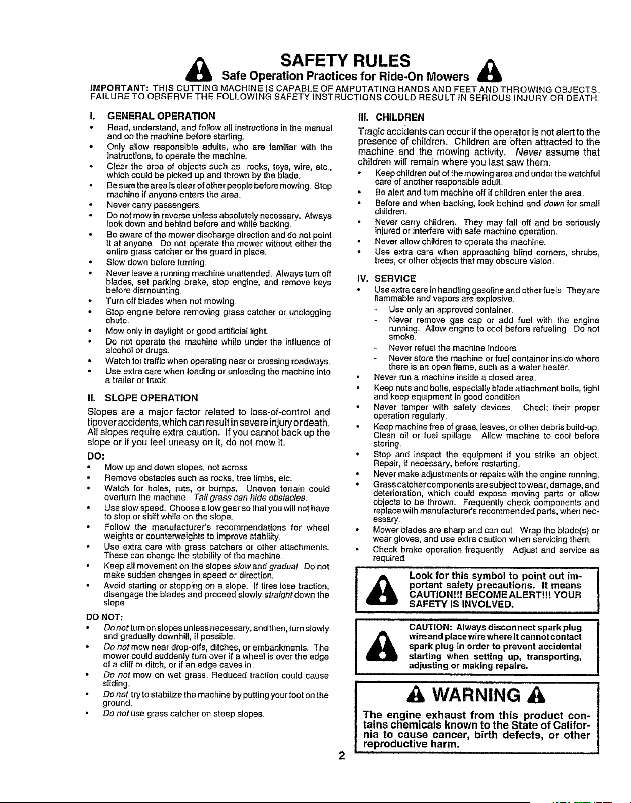
Look for this symbol to point out im-
portant safety precautions. It means
CAUTION!!! BECOME ALERT!!! YOUR
SAFETY' IS INVOLVED.
iii ll/uli lll
,Jllllll,uuui/iull/i iii ii ,i i llll i i
CAUTION: Always disconnect spark plug
wire and place wire where it can not contact
spark plug in order' to prevent accidental
starting when setting up, transporting,
adjusting or making repairs.
IHIJ"IIW"U I I
& WARNING & I
"l'he engine exhaust from this product con-
tains cliemicals known to the State of Califor-
nia to cause cancer, birth defects, or other
repr°ductive harm. .......

CONGRATULATIONS on your purchase of a Sears
Tractor,, It has been designed, engineered and manufac-
tured to give you the best possible dependability and
performance.
Should you experience any problem you cannot easily
remedy, please contact your nearest Sears Authorized
Service CentedDepartmenL We have competent, weIF
trained technicians and the proper tools to service or repair
this tractor+.
Please read and retain this manual The instructions will
enable you to assemble and maintain your unit properly.
Always observe the "SAFETY RULES".
MODEL
NUMBER
SERIAL
NUMBER
917+251550
DATE OF PURCHASE
THE MODELAN D SERIAL NUMBERS WILL BE FOUND
ON A PLATE UNDER THE SEAT.
YOU SHOULD RECORD BOTH SERIAL NUMBER AND
DATE OF PURCHASE AND KEEP IN A SAFE PLACE
FOR FUTURE REFERENCE,
MAINTENANCE AGREEMENT
A Sears Maintenance Agreement is available on this prod-
uct. Contact your nearest Sears store for details.
PRODUCT SPECIFICATIONS
HORSEPOWER: 225
GASOLINE CAPACITY 3+5GALLONS
AND TYPE: UNLEADED REGULAR
OIL TYPE (API-SF!SG): SAE 10W30 (above 32°F)
SAE 5W-30 (below 32°F)
OIL CAPACITY: W/FILTER: 4.2 PINTS
W!O FILTER: 3.7 PINTS
SPARK PLUG: CHAMPION RC12YC
(GAP: +030")
VALVE CLEARANCE: NOT ADJUSTABLE
GROUND SPEED (MPH):' Forward LO HI
1st 0.74 1_73
2nd 1.39 3..26
3rd 229 5.,40
Reverse 0.89 2.09
TRANSAXLE OIL 4 QUARTS
CAPACtTY AND TYPE: SAE 30 API+SG
TIRE PRESSURE: FRONT: 14 PSI
REAR: 10 PSI
CHARGING SYSTEM: 15 AMPS @ 3600 RPM
BATTERY: AMP]HR: 35
MIN_.CCA: 280
CASE SIZE: U1R
BLADE BOLT TORQUE: 30-35 FT.+LBS+
CUSTOMER RESPONSIBILITIES
o Read and observe the safety rules..
, Fo!low a regular schedule in maintaining, caring for and
using your tractor.
• Follow the instructions under"Customer Responsibili-
ties and Storage sections of this owner s manual.
WARNING: This tractor is equipped with an internal
combustion engine and should not be used on or near any
unimproved forest-covered, brush-covered or grass-coy-
ered land unless the engine's exhaust system is equipped
with a spark arrester meeting applicable local or state laws
(if any),, If a spark arrestor is used, it should be maintained
in effective working order by the operator.
In the state of California the above is required by law
(Section 4442 of the California Public Resources Code)+
Other states may have similar laws+ Federal laws apply on
federal lands. A spark arrester for the muffler is available
through your nearest Sears Authorized Service Center/
Department (See REPAIR PARTS section of this manual),
IIIIH lUUJJJJJJiiJJllllllllllllllllli iiii , ijjjjIJLIIIIiiiiiii iiiiiii
LIMITED TWO YEAR WARRANTY ON ELECTRIC START RIDING EQUIPMENT
For two (2) years from the date of purchase, if this dding equipment is maintained, lubricated and tuned up according to the
instructionsin the owner's manual, Sears will repair or replace, free of charge, any parts found to be defective in material or
workmanship.
This Warranty does not cover:
• Expendable items which become worn during normal use, such as btades, spark plugs, air cleaners and bells
• Tire replacement or repair caused by punctures from outside objects, such as nails, thorns, stumps, or glass.
• Repairs necessary because of operator abuse, negligence, improper storage or accident or the failure to maintain the
equipment according to the instructionscontained in the owner's manual
• Riding equipment used for commercial or rental purposes_
LIMITED 90 DAY WARRANTY ON BATTERY
For ninety (90) days from date of purchase, if any battery included with this riding equipment proves defective in material or
workmanship and our testingdetermines the battery will not hold a charge, Sears will replace the battery at no charge+
WARRANTY SERVICE IS AVAILABLE BY RETURNING THE RIDING EQUIPMENT TO THE NEAREST SEARS SERVICE
CENTER/DEPARTMENT IN THE UNITED STATES,
This Warranty gives you specific legal rights, and you may also have other rights which may vary Irom state to state.
SEARS, ROEBUCK AND CO+, D/817 WA, HOFFMAN ESTATES, ILLINOIS 60179
3
SAFETY RULES ............................................................ 2
PRODUCT SPECIFICATIONS ...................................... 3
CUSTOMER RESPONSIBILITIES ..................... 3, 1548
WARRANTY .................................................................. 3
TRACTOR ACCESSORIES .......................................... 5
ASSEMBLY ............................................................. 7-10
OPERATION .......................................... ................ 11-14
MAINTENANCE SCHEDULE ..................................... 15
SERVICE AND ADJUSTMENTS ........................... 19-26
STORAGE ................................................................... 27
TROUBLESHOOTING ........................................... 28-29
REPAIR PARTS - TRACTOR ................................ 31-49
REPAIR PARTS - ENGINE .................................... 50-57
PARTS ORDERING/SERVICE ............... BACK COVER
INDEX
A
Accessories ...........................................................5
Adjustments:
Brake ....................................................21
Carburetor .................................................26
Clutch Putiey ........................................21
Gauge Wheels .......................................13
Mower
Front-To-Back ................,,...............20
Side-To-Side .........................................19
Throttle Control Cable ..........................23
Air Filter, Engine...........................................18
Air Screen, Engine ...........................................18
Assembly ......................................................7-10
B
Battery:
Charging ....................................................8
Cleaninc ................................................16
Starting with Weak Battery ...............23
Storage .................................................27
Terminals ..................................................16
Belt:
Motion Drive
Removal/Replacement ...............22
Mower' Drive
Removal/Replacement ........... 20
Mower' Blade Drive
Removal/Replacement ..............2t
Blade:
Sharpening ...........................................16
Replacement ............................................16
Brake Adjustment ................................................21
C
Carburetor Adjustment ............................26
Clutch Pulley ...................................................21
Controls, Tractor .................................................11
Customer Responsibilities...................15-! 8
Engine:
Air Filter ...................................................18
A# Scree ........................................18
Cooling Fins ................................18
Engine Oil .................................................17
Fuel Filter .......................................18
Spark Plug(s) ......................................18
Tractor:
Battery ................................................17
Blade ....................................................16
Lubrication Chart ....................... 15
Maintenance Schedule ..................I5
Tire Care .....................................8,16,23
Transaxle ..................................................16
Cutting Height, Mower ..................................12
E
Electrical:
Interlocksand Relays ......................23
Schematic .......................................................31
Wiring Diagram .....................................32
Engine:
Air Filter .........................................................18
Air Screen ................................................18
Cooling Fins ............................................18
Oil Change ...................................................17
Oil Level ....................................................t3,17
Oil Type ...........................................17
Preparation ...............................................13
Repair Parts ......................................50-57
Starting .........................................................14
Storage .....................................................27
F
Filter:
Air Filter ..........................................................18
Fuel .................................................................18
Oil ................................................................17
Fuel:
Storage ..............................................27
Type ..........................................................12
Fuse ........................................................23
H
Headlights .........................................................23
Hood Removal/Installation ......................24
L
Leveling Mower Deck ...................................19
Lubrication:
Chart .............................................. 15
M
Maintenance Schedule .................................15
Mower:
Adjustment, Front-to-Back ..................20
Adjustment, Side-to-Side ....................19
Blade Sharpening ...........................16
Blade Replacement ....................................16
Cutting Height ............................... 12
Installation....................................................19
Operation ............................................................13
Removal ......................i..............................19
Mowing Tips .....................................................14
Muffler ..................................................................18
Spark Arrester .....................................3,40
Oi!:
O
Cold Weather Conditions ............13,17
Engine .........................................................17
Storage ...................................................27
Operation .....................................................11-14
Operating Mower ..........................................13
Options:
Accessories ..................................................5
Spark Ar-rester _.....................................3,40
P
Parking Brake .........................................12
PartsBag .........................................................6
Parts, Replacement/Repair. .............31-49
Product Specifications ...................................3
R
Repair Parts ..................................................31-49
S
Safety Rules ..................................................2
Seat .................................................................8
Service and Adjustments ...................19-26
Carburetor .....................................................26
Clutch Pulley ......................................21
Fuse ............................................................. 23
Hood Removal/Installation ................24
Motion Drive Belt
Removal/Replacement ...................22
Mower Dive Belt
Removal/Rep[acement ..............20
Mower' Blade Drive
Removal/Replacement ...............21
Mower Adjustment
Front-to.Back ...............................20
Side-to-Side ......................................20
Mower Removal ......................................19
Tire Care ................................................ 8,16,23
Slope Guide Sheet ........................................59
Spark Plug(s) .................................................18
Specifications .............................................................3
Starting the Engine ......................... 13-14
Steedng Wheel .........................................7,22
Stopping the Tractor'. ...............................12
Storage .................................................................27
T
Throttle Control Cable Adjustment ...... 25
Tires...............................................:..................8,t6,23
TroubEe Shooting Chart ......................28-29
Transaxie .....................................................................16
Warranty ..............................................................3
Wiring Diagram ........................................................32
Wiring Schematic .....................................31
4
ACCESSORmES
AND ATTACHIVIENTS
These accessories and attachments were available throughmost Sears retail outiets and service centers when the tractor was purchased.
Most Sears stores can order these items for you when you provide the model number of your tractor,
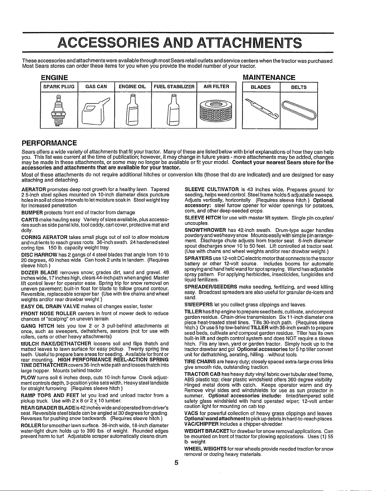
ENGINE
SPARK PLUG
GAS CAN ENGINE OIL
FUEL STABILIZER
AtR FILTER
MAINTENANCE
BLADES ] BELTS t1
PERFORMANCE
Sears offersa wide variety of attachments that fit your tractor.. Many of these are listedbelow with bdef explanations of how they can help
you° This list was current at the time of publication; however, it may change in future years - more attachments may be added changes
may be made in these attachments, or some may no longer be available or fit your model Contact your nearest Sears store for the
accessories and attachments that are available for your tractor.
Most of these attachments do not require additional hitches or conversion kits (those that do are indicated) and are designed for easy
attaching and detaching,
AERATOR promotes deep root growth for a healthy lawn. Tapered
25-inch steel spikes mounted on 10-inch diameter discs puncture
holestnsotlatcloseintervalstoletmoisturesoakin Steelweight tray
for increased penetration
BUMPER protects front end of tractor from damage.
CARTS make hauling easy Variety of sizes available, ptus accesso-
ries such as side panel kits, tool caddy, cart cover, protective mat and
dolly,
CORING AERATOR takes small plugs out of soil to allow moisture
andnutrienlstoreachgrassroots 36-inahswath, 24 hardened steel
coring tips, 150 Ib,, capacity weight tray,
DISC HARROW has 2 gangs of 4 steel blades that angle from 10 to
20 degrees, 40 inches wide Can hook 2 units in tandem, (Requires
sleeve hitch.)
DOZER BLADE removes snow; grades dirt, sand and gravel, 48
inches wide, 17 inches high, clears 44qnch path when angled. Master
lift control lever for operator ease. Spring tdp for snow removal on
uneven pavement; built-in float for blade to follow ground contour.
Reversible, replaceable scraper bar, (Use with tire chains and wheel
weights and/or rear drawbar weight,)
EASY OIL DRAIN VALVE makes oil changes easier, taster,
FRONT NOSE ROLLER canters in front of mower deck to reduce
chances of "scalping" on uneven terrain.
GANG HITCH Iets you tow 2 or 3 pull-behind attachments at
once, such as sweepers, dethatchers, aerators (not for use with
rollers, carts or other heavy' attachments)
MULCH RAKE/DETHATCHER loosens soil and flips thatch and
matted leaves to lawn surface for easy pickup. Twenty spring tine
teeth, Usefulto prepare bare areas forseeding, Avai]ablefor front or
rear mounting. HIGH PERFORMANCE REEL-ACTION SPRING
TINE DETHATCHER covers 36-inch wide path and tosses thatch into
large hopper, Mounts behind tractor,
PLOW turns soil 6 inches deep, cuts 10-inch furrow, Crank adjust-
ment controls depth, 3-position yoke sets width. Heavy steel iandside
for straight furrowing, (Requires sleeve hitch )
RAMP TOPS AND FEET let you load and unload tractor from a
pickup truck, Use wilh 2 x 8 or 2 x 10 lumber°
REAR GRADER BLADEfs 42 inches wide and operated from drwer's
seat. Reversible steel blade can be angled at 30 degrees for grading.
Reverses forpushing snow backwards (Requires sleeve hitch, )
ROLLER for smoother lawn surface, 36-inch wide, 18-inch diameter
water-tight drum holds up to 390 lbs, of weight. Rounded edges
prevent harm to turf, Adiustabte scraper automaticalfy cleans drum
SLEEVE CULTIVATOR is 43 inches wide. Prepares ground for
seeding, helps weed control Steel frame holds 5 adjustable sweeps.
Adjusts vertically, horizontally, (Requires sleeve hitch.) Opttonat
accessory: steel furrow opener for wider openings for potatoes,
corn, and other deep.seeded crops,
SLEEVE HITCH for use with master lift system,, Singie pin couples/
uncouples,
SNOWTHROWER has 42-inch swath., Drum-type auger handles
powdery and wellheavy snow, Mounts easilywith simple pin arrange-
ment. Discharge chute adjusts from tractor seat, 6-inch diameter
spout discharges snow 10 to 50 feet., Lift controlled at tractor seat,,
(Use with chains and wheel weights and/or rear drawbar weight,)
SPRAYERS use 12-volt DC electric motor that connects to the tractor
baltery or other 12-volt source, Includes booms for automatic
spraying and hand heldwand for spot spraying, Wand has adjustable
spray pattern For applying herbicides, insecticides, fungicides and
liquid fertilizers,
SPREADERISEEDERS make seeding, fertilizing, and weed killing
easy, Broadcast spreaders are also useful for granular de-icers and
sand.,
SWEEPERS let you collect grass clippings and leaves,,
TILLER has 8 hp engine to prepare seed beds, cultivate, and compost
garden residue. Chain-ddve transmission. Six 11-inch diameter one
piece heat4reated steel tines. Tills 30-inch path° (Requires sleeve
hitch.) Or use 5 hp tow-behind TILLER with 36-inch swath to prepare
seed beds, cultivate and compost garden residue, Tiller has its own
built-in lift and depth control system and does NOT require a sleeve
hitch° Fits any lawn, yard or garden tractor. Simply hook up to the
tractor drawbar and go! Optional accessories for 5 hp tiller convert
unit for dethatching, aerating, hilling..,without tools.
TIRE CHAINS are heavy duty; closely spaced extra-large cross links
give smooth fide, oulstanding traction°
TRACTOR CAB has heavy duty vinyl fabric over tubular steel frame,
ABS plastic top; clear plastic windshield offers 360 degree visibility
Hinged metal doors with catch. Keeps operator warm and dry.
Remove vinyl sides and windshields for use as sun protector in
summer. Optional accessories include: tintedltempered solid
safety glass windshield with hand operated wiper;, 12-volt amber
caution light for mounting on cab top,
VACS for powerful collection of heavy grass clippings and leaves
Optional wand attachment to pick up debris in hard-to-reach places,
VAC/CHIPPER includes a chipper-shredder,
WEIGHT BRACKET for drawbar for snow removal applications,, Can
be mounted on front of tractor for plowing applications, Uses (1) 55
Ib weight
WHEEL WEIGHTS for rear wheels provide needed traction for snow
removal or dozing heavy materials,
CONTENTS OF HARDWARE PACK
,,,,,, ,,, ,,,,,,,,,,,,,llllllllll i ill
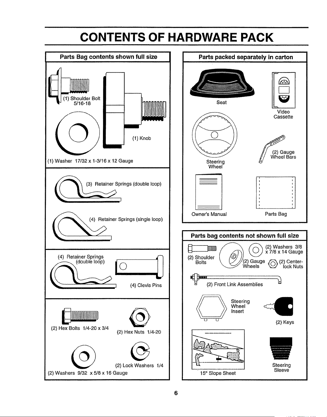
Parts Bag contents shown full size
(1) Shoulder Bolt
5/16-18
__ 1
(t) Knob
(1) Washer 17/32 x 1-3/16 x 12 Gauge
SPlrings (double loop)
_,. (4) Retainer Springs (single loop)
(4) Clevis Pins
(2) Hex Bolts 1/4-20 x 3/4
@
(2) Hex Nuts 1/4-20
__ (2) Lock Washers 1/4
(2) Washers 9/32 x 5/8 x 16 Gauge
: llllllll
Parts packed separately in carton
Seat
Steering
Wheel
Owner's Manual
Video
Cassette
auge
Bars
H
l
Parts Bag
Parts bag contents not shown full size
/_, _ (2)Washers 3/8
(2) Shoulder (/_) k___x7/Sx14Gauge
Bolts \ I_J//(2) Gauge _ (2) Center-
Wheels _ lock Nuts
_"="(2) Fr0nl
Link Assemblies
Steering
Wheel
Insert
(2) Keys
15° Slope Sheet
6
Steering
Sleeve
ASSEMBLY
i,llll illJl ui N,I i
Your new tractorhas been assembted at the factorywith the exceptionofthosepartsleft unassembledfor shippingpurposes°
To ensure safe and proper operation of your tractorall partsand hardware youassemble must be tightened securely. Use
the correct tools as necessary to insure proper tightness_
TOOLS REQUIRED FOR ASSEMBLY
A socket wrenchset will make assembly easier° Standard
wrench sizes are listed.
(2) 7/16" wrenches Tire pressure gauge
(1) I/2" wrench Utility knife
(1) 9/16" wrench
(1) 3/4" socket with drive ratchet
When right or left hand is mentioned in this manual, it
means when you are in the operating position (seated
behind the steering wheel).
TO REMOVE TRACTOR FROM CARTON
UNPACKCARTON
° Remove all accessible loose parts and parts cartons
from carton (See page 6).
• Cut, from top to bottom, along lines on all four corners
of carton, and lay panels flat.
BEFORE ROLLING TRACTOR OFFSKID
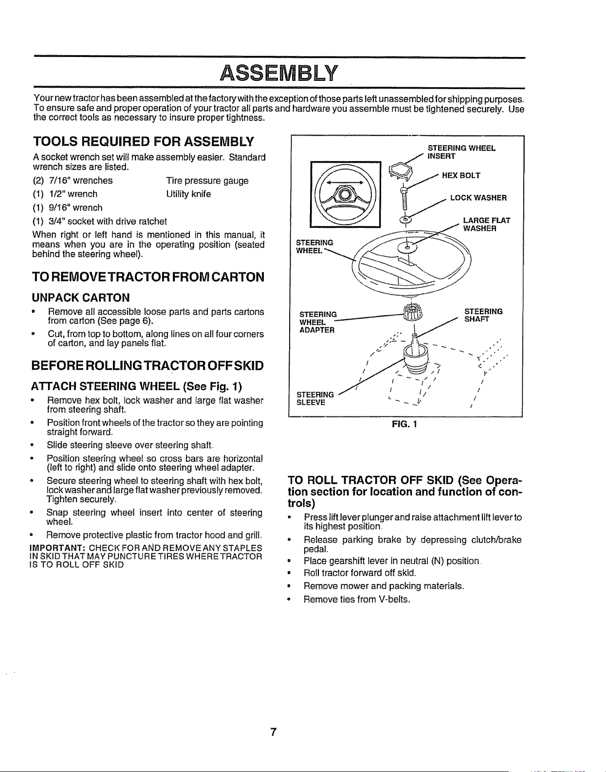
ATTACH STEERING WHEEL (See Fig. 1)
• Remove hex bolt, lock washer and large flat washer
from steering shaft.
° Position front wheels of the tractor so they are pointing
straight forward..
, Slide steering sleeve over steering shaft..
° Position steering wheel so cross bars are horizontal
(left to right) and slide onto steering wheel adapter°
° Secure steering wheel to steering shaft with hex bolt,
lock washer and large flat washer previously removed°
Tighten securely_
° Snap steering wheel insert into center of steering
wheel.
° Remove protective plastic from tractor hood and grill
IMPORTANT: CHECK FORAND REMOVE ANY STAPLES
IN SKID THAT MAY PUNCTURE TIRES WHERETRACTOR
IS TO ROLL OFF SKID
STEERING WHEEL
SLEEVE
FIG. 1
TO ROLL TRACTOR OFF SKID (See Opera-
tion section for location and function of con-
trols)
° Press lift lever plunger and raise attachment lift lever to
its highest position.
, Release parking brake by depressing clutch/brake
pedal_
° Place gearshift lever in neutral (N) position.
° Roll tractor forward off skid..
° Remove mower and packing materials_
, Remove ties from V-belts.
7
ii i iillll
ASSEMBLY
CONNECT BATTERY (See Fig. 2)
i ,,,,uJnuJt
CAUTION: Do not short battery termi-
nals. Before connecting battery, re-
move metal bracelets, wristwatch
bands, rings, etc.
Positive terminal must be connected
first to prevent sparking from acciden-
tal grounding.
• Lifthood to raised position°
• Open termina! access doors, remove terminal protec-
tive caps and discard.
. If this battery is put into service after month and year
indicated on label (label located between terminals)
charge battery for minimum of one hour at 6-10 amps.
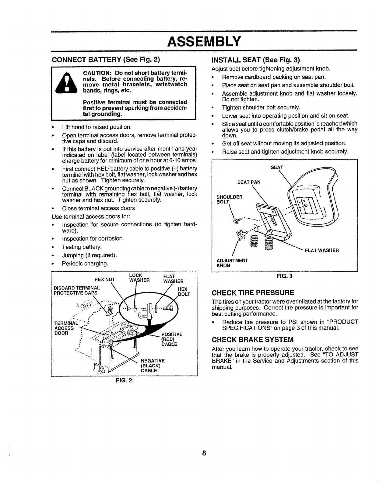
• First connect RED battery cable to positive (+) battery
terminal with hex bolt, fiat washer, lockwasher and hex
nut as shown Tighten securely.
• Connect BLACK grounding cable to negative (-)battery
terminal with remaining hex bolt, flat washer, lock
washer and hex nut. Tighten securely.
• Close terminal access doors..
Use terminal access doors for:
• Inspection for secure connections (to tighten hard-
ware),
• inspectionfor corrosion_
• Testing battery_
• Jumping (if required).
• Periodic charging.
INSTALL SEAT (See Fig. 3)
Adjust seat before tighteningadjustment knob.
• Remove cardboard packing on seat pan
• Place seat on seat pan and assemble shoulder bolt,
• Assemble adjustrnent knob and fiat washer loosely,
Do not tighten.
• Tighten shoulder bolt securelyo
• Lower seat intooperating positionand sit on seat°
° Slide seat untilacomfortableposition is reached which
allows you to press clutch/brake pedal all the way
down_
• Get off seat without moving its adjusted position_
• Raise seat and tighten adjustment knob securety_
SEAT PAN
SHOULDER
BOLT
SEAT
ADJUSTMENT
KNOB
FLAT WASHER
LOCK
HEX NUT WASHER
DISCARDTERMINAL X
PROTECTIVE CAPS "\
ACCESS
: I _.,'_ " J
FLAT
WASHER
CABLE
NEGATIVE
(BLAC_
CABLE
FIG. 3
CHECK TIRE PRESSURE
The tires on your tractor were overinflated at the factory for
shipping purpose& Correct tire pressure is important for
best cutting performance..
• Reduce tire pressure to PSI shown in "PRODUCT
SPECIFICATIONS" on page 3 of this manual.
CHECK BRAKE SYSTEM
After you learn how to operate your tractor,check to see
that the brake is properly adjusle& See "TO ADJUST
BRAKE" in the Service and Adjustments section of this
manual
FIGo2
8
ASSEMBLY
INSTALL MOWER AND DRIVE BELT
(See Figs. 4 and 7)
Be sure tractor is on love! surface and mower suspension
arms are raised with attachment lift control,, Engage park-
ing brake°
o Cut and remove ties securing anti-sway bar and belts.
Swing anti-sway bar to left side of mower deck,
= Slide mower under tractorwith discharge guardto right
side of tractor.
IMPORTANT: CHECK BELT FOR PROPER ROUTING IN
ALL MOWER PULLEY GROOVES. INSTALL BELT INTO
ELECTRIC CLUTCH PULLEY GROOVE.,
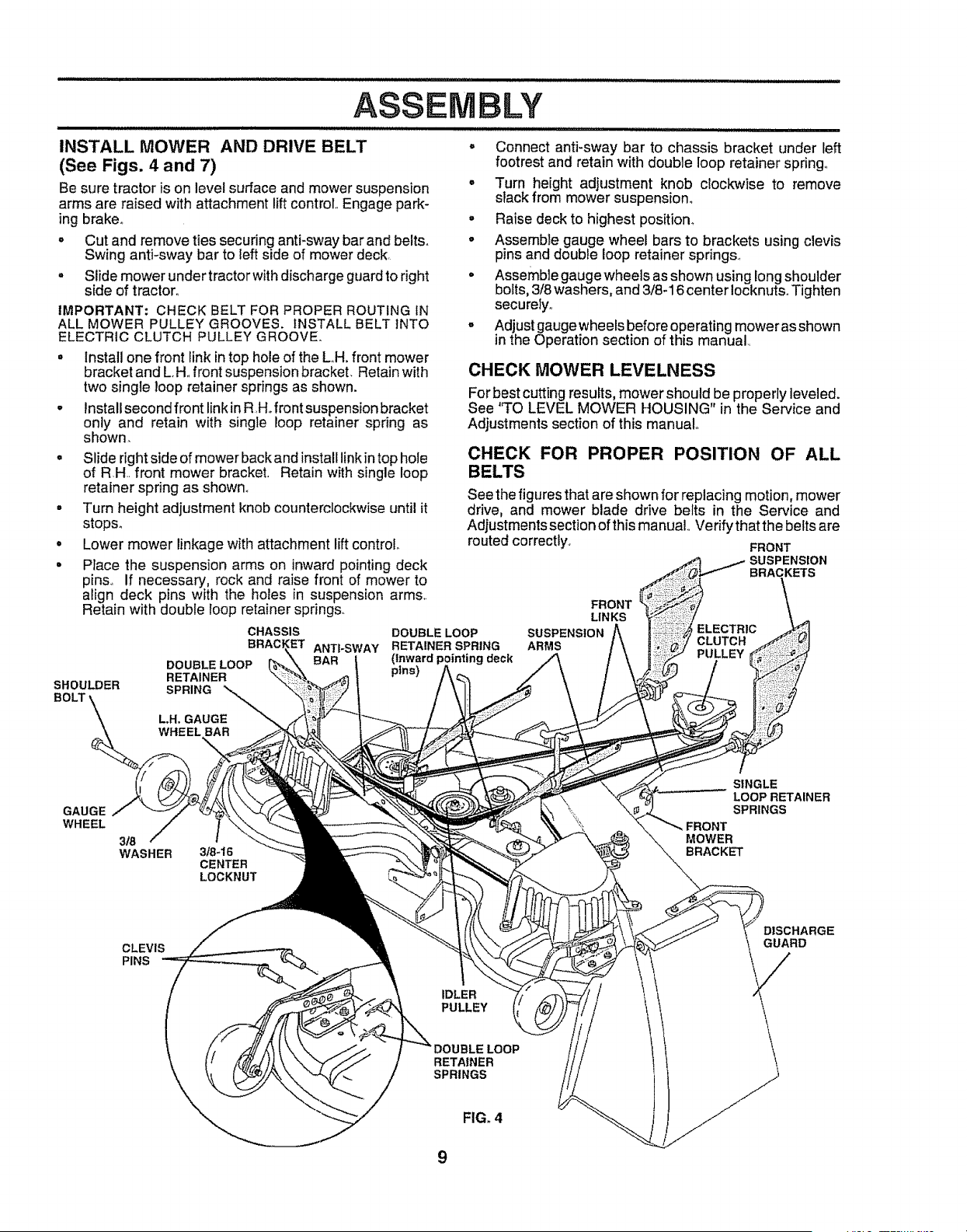
• Install one front link intop hole of the LH, front mower
bracket and L,H,,front suspension bracket. Retain with
two single loop retainer springs as shown.
° Install second front linkin R,Hofront suspension bracket
onty and retain with single loop retainer spring as
shown.
• Slide right side of mower back and install linkin top hole
of RH.. front mower bracket. Retain with single loop
retainer spring as shown°
• Turn height adjustment knob counterclockwise until it
stops°
• Lower mower linkage with attachment lift control
° Place the suspension arms on inward pointing deck
pins., If necessary', rock and raise front of mower to
align deck pins with the holes in suspension arms,.
Retain with double roop retainer springs.
SHOULDER
BOLT'
CHASSIS
BRACI
DOUBLELOOP
RETAINER
SPRING
ANTI-SWAY
= Connect anti-sway bar to chassis bracket under left
footrest and retain with double loop retainer spring.,
° Turn height adjustment knob clockwise to remove
slack from mower suspensiom
° Raise deck to highest position°
° Assemble gauge wheel bars to brackets using clevis
pins and doubie loop retainer springs.,
• Assemble gaugewheels as shown using long shoulder
bolts, 3/8 washers, and 3/8-16 center Iocknuts.Tighten
securely,,
= Adjustgaugewheels before operating mowerasshown
in the Operation section of this manual,,
CHECK MOWER LEVELNESS
For best cutting results, mower should be properly leveled.
See 'q'O LEVEL MOWER HOUSING" in the Service and
Adjustments section of this manual°
CHECK FOR PROPER POSITION OF ALL
BELTS
See the figures that are shown for replacing motion, mower
drive, and mower blade drive belts in the Service and
Adjustmentssectionofthis manual Verifythatthe beltsare
routed correctly., FRONT
SUSPENSION
BRACKETS
DOUBLE LOOP
RETAINER SPRING
(Inward p, deck
pins)
FRONT
LINKS
SUSPENSION ELECTRIC
ARMS CLUTCH
PULLEY
L.H, GAUGE
WHEEL BAR
GAUGE
WHEEL
3_
WASHER
3/8-16
CENTER
LOCKNUT
SINGLE
LOOP RETAINER
SPRINGS
FRONT
MOWER
BRACKET
CLEVIS
PINS
IDLER
PULLEY
DISCHARGE
GUARD
LOOP
RETAINER
SPRINGS
FIG. 4
9
ASSEMBLY
v" CHECKLIST
BEFORE YOU OPERATE AND ENJOY YOUR NEW
TRACTOR, WE WISH TO ASSURE THAT YOU RECEIVE
THEBEST PERFORMANCEAND SATISFACTION FROM
THIS QUALITY PRODUCT.
PLEASE REVIEW THE FOLLOWING CHECKLIST:
,/ All assembly instructions have been completed.
,/ No remaining loose parts in carton_
,/ Battery isproperly prepared and charged. (Minimum
1 hour at 6 amps)..
,f Seat is adjusted comfortably and tightened securely.
#' All tires are propedy inflated. (For shipping purposes,
the tires were overinflated at the factory)..
J Be sure mower deck is properly leveled side-to-side/
front-to-rear for best cutting results. (Tires must be
properly inflated for leveling).
J Check mower and drive belts. Be sure they are routed
properly around pulleys and inside all belt keepers_
J Check wiring.. See that all connections are still secure
and wires are properly clamped.
WHILE LEARNING HOW TO USE YOUR TRACTOR,
PAYEXTRA ATTENTION TO THE FOLLOWING IMPOR-
TANT ITEMS:
,/ Engine oil is at proper level.
v" Fuel tank is filled with fresh, clean, regular unleaded
gasoline._
#" Become familiar' with all controls - their location and
function. Operate them before you start the engine..
v" Be sure brake system is in safe operating condition°
10
OPERATION
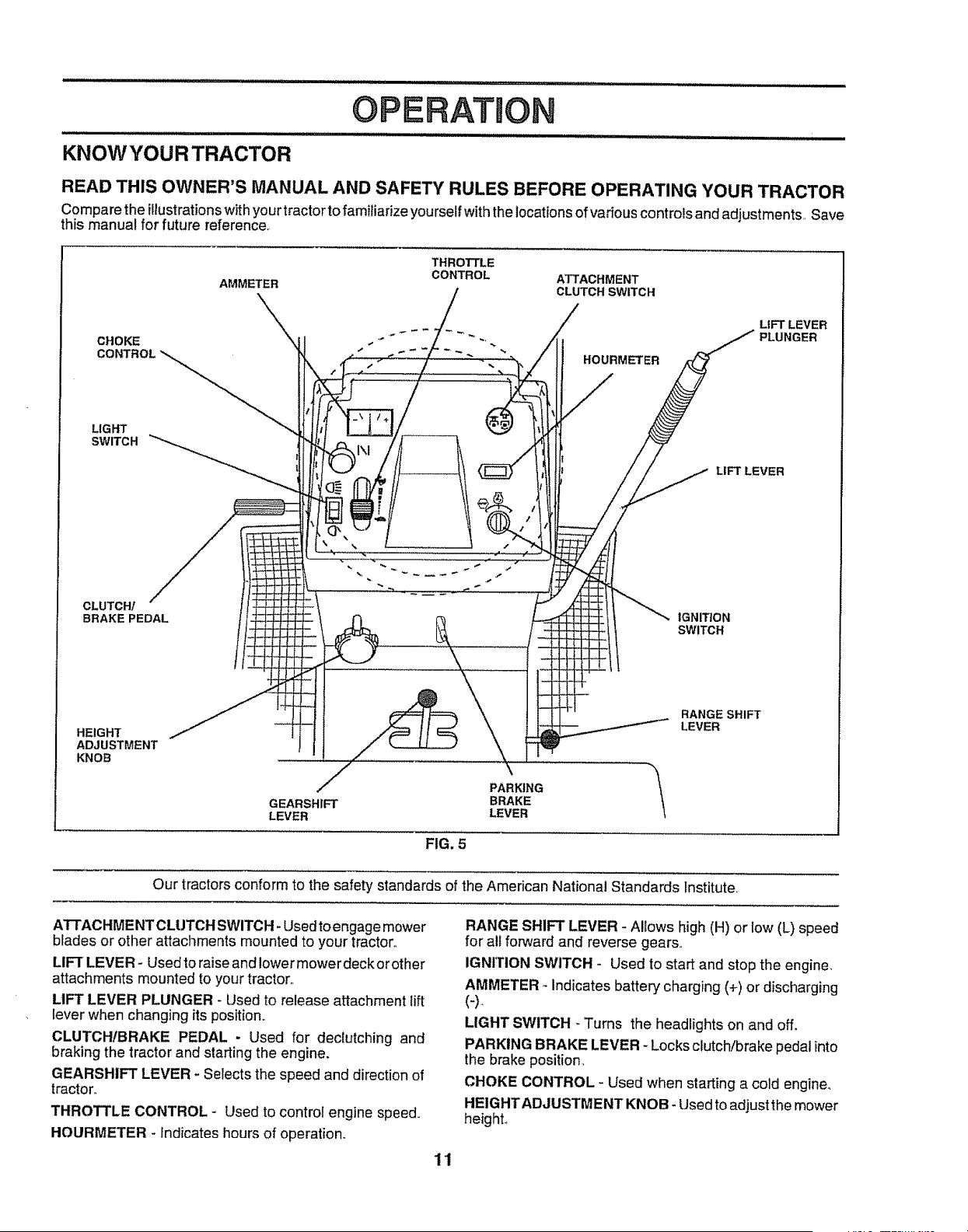
KNOWYOURTRACTOR
READ THIS OWNER'S MANUAL AND SAFETY RULES BEFORE OPERATING YOUR TRACTOR
Compare the illustrationswithyour tractorto familiarize yourself withthe locationsof variouscontrolsand adjustments, Save
this manual for future reference.
CHOKE
CONTROL
LIGHT
SWITCH
CLUTCH/
BRAKE PEDAL
THROTTLE
AMMETER CONTROL ATTACHMENT
CLUTCH SWITCH
"\_'\. \ LIFT LEVER
PLUNGER
HOURMETER
LIFT LEVER
IGNITION
SWITCH
HEIGHT
ADJUSTMENT
KNOB
RANGE SHIFT
LEVER
PARKING _'_\lGEARSHIFT BRAKE
LEVER LEVER
FIG. 5
Our tractorsconform to the safety standards of the American National Standards Institute.
ATTACHMENTCLUTCH SWITCH +Usedto engage mower
blades or other attachments mounted to your tractor,,
LIFT LEVER- Used to raise and lower mower deck or other
attachments mounted to your tractor.,
LIFT LEVER PLUNGER - Used to release attachment lift
lever when changing its position,,
CLUTCHtBRAKE PEDAL - Used for dectutching and
braking the tractor and starting the engine.
GEARSHIFT LEVER + Selects the speed and direction of
tractor.
THROTTLE CONTROL + Used to controi engine speed+
HOURMETER +Indicates hours of operation°
RANGE SHIFT LEVER - Allows high (H) or low (L) speed
for all forward and reverse gears,,
IGNITION SWITCH - Used to start and stop the engine,
AMMETER - Indicates battery charging (+) or discharging
LIGHT SWITCH - Turns the headlights on and off.
PARKING BRAKE LEVER - Locks clutch!brake pedal into
the brake position_
CHOKE CONTROL - Used when starting a cold engine_
HEIGHTADJUSTMENT KNOB- Used to adjust the mower
height+
11
OPERATION
.................................. iiiii iiii iii1,11 i,,i,
, ,, , ,,,, ,, ,,,, ,,, ,,,,,,,,,,,,,,, ,liliiH
The operation of any tractor can result in foreign objects thrown into the eyes, which can result
in severe eye damage. Always wear safety glasses or eye shields while operating your tractor
or performing any adjustments or repairs. We recommend a wide vision safety mask over the
spectacles or standard safety glasses.
iiiiii ..............................................
HOW TO USE YOUR TRACTOR
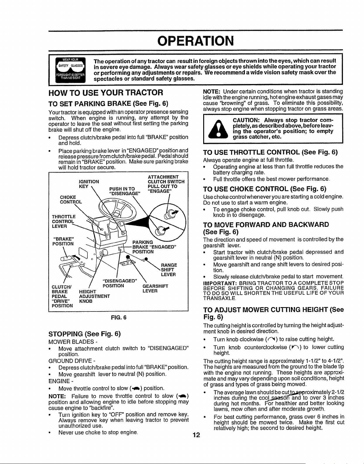
TO SET PARKING BRAKE (See Fig. 6)
Your'tractor isequipped withan operator presence sensing
switch. When engine is running, any attempt by the
operator to leave the seat without first setting the parking
brake will shut off the engine.
• Depress clutch/brake pedal into full "BRAKE" position
and hold_
• Place parking brake lever in"ENGAGED" position and
release pressure from clutch/brake pedal,, Pedalshould
remain in"BRAKE" position,, Make sure parking brake
will hold tractor secure_
ATTACHMENT
IGNITION CLUTCH SWITCH
KEY -- USH IN TO PULL OUT TO
P_ .......... "ENGAGE"
CHOKE "\ _._-,-,,--_ ",,, /
CONTROL ._ .'_V_-_f-.._"-_ \ _..L
"BRAKE" :-V "-J
PARKING
POSITION -.... _ _-----'-'_ _
\ _ _,_ BRAKE "ENGAGED"
\ l_ J F_L')J_T-_--_PosrnoN
"_\/ '.".. _ -J/ "" I \ _, SHIFT
,.% / ......!........ \ LEVER
/ "DISENGAGED" \
CLUTCH/ / POSITION GEARSHIFT
BRAKE HEIGHT LEVER
PEDAL ADJUSTMENT
"DRIVE" KNOB
POSITION
FIG. 6
STOPPING (See Fig. 6)
MOWER BLADES -
• Move attachment clutch switch to "DISENGAGED"
position,,
GROUND DRIVE -
• Depress clutch/brake pedat into full "BRAKE" position.
° Move gearshift lever to neutral iN) position.
ENGINE -
• Move throttle control to slow (,,J_) position.
NOTE: Failure to move throttle control to slow (.,m_)
position arid allowing engine to idle before stopping may
cause engine to "backfire".
• Turn ignition key to "OFF" position and remove key.
Always remove key when leaving tractor to prevent
unauthorized use,.
° Never use choke to stop engine,.
NOTE: Under certain conditions when tractor is standing
idlewiththe engine_nning, hotengine exhaustgases may
cause "browning" of grass. To eliminate this possibility,
always stop engine when stopping tractor on grass areas.
CAUTION: Always stop tractor com-
pletely,asdescribed above, before leav-
ing the operator's position; to empty
grass catcher, etc.
TO USE THROTTLE CONTROL (See Fig. 6)
Always operate engine at full throttle_
° Operating engineat less than full throttle reduces the
battery chargingrate°
• Full throttleoffersthe best mower performance_
TO USE CHOKE CONTROL (See Fig. 6)
Use choke controlwhenever you are startinga coldengine.
Do not use to start a warm engine_
° To engage choke control,pull knob ouL Slowly push
knob in to disengage.
TO MOVE FORWARD AND BACKWARD
(See Fig. 6)
The directionand speed of movement iscontrolledby the
geat'shift lever.
° Start tractor' with clutch/brake pedal depressed and
gearshift lever in neutral iN) position.
- Move gearshift and range shift levers to desired posi-
tion.
• Slowly release clutch/brake pedal to start movement.
IMPORTANT: BRING TRACTOR TO A COMPLETE STOP
BEFORE SHIFTING OR CHANGING GEARS. FAILURE
TO DO SO WILL SHORTEN THE USEFUL LIFE OF YOUR
TRANSAXLE.
TO ADJUST MOWER CUTTING HEIGHT (See
Fig. 6)
The cutting height is controlled by turning the height adjust-
ment knob in desired direction.
• Turn knob clockwise (("_) to raise cutting height.
- Turn knob counterclockwise (1_'_) to lower cutting
height.
The cutting height range is approximately 1-1/2" to 4-1/2",
The heights are measured from the ground to tile blade tip
with the engine not running. These heights are approxi-
mate and may vary depending upon soil conditions, height
of grass and types of grass being mowed,.
• The average lawn should be cutt=t.J.g.approximately2-1/2
inches during the cool_d'_ and to over 3 inches
during hot months, For healthier and better looking
lawns, mow often and after moderate growth_
• For best cutting performance, grass over 6 inches in
height should be mowed twice. Make the first cut
relativelyhigh; the second to desired height.
12
OPERATION
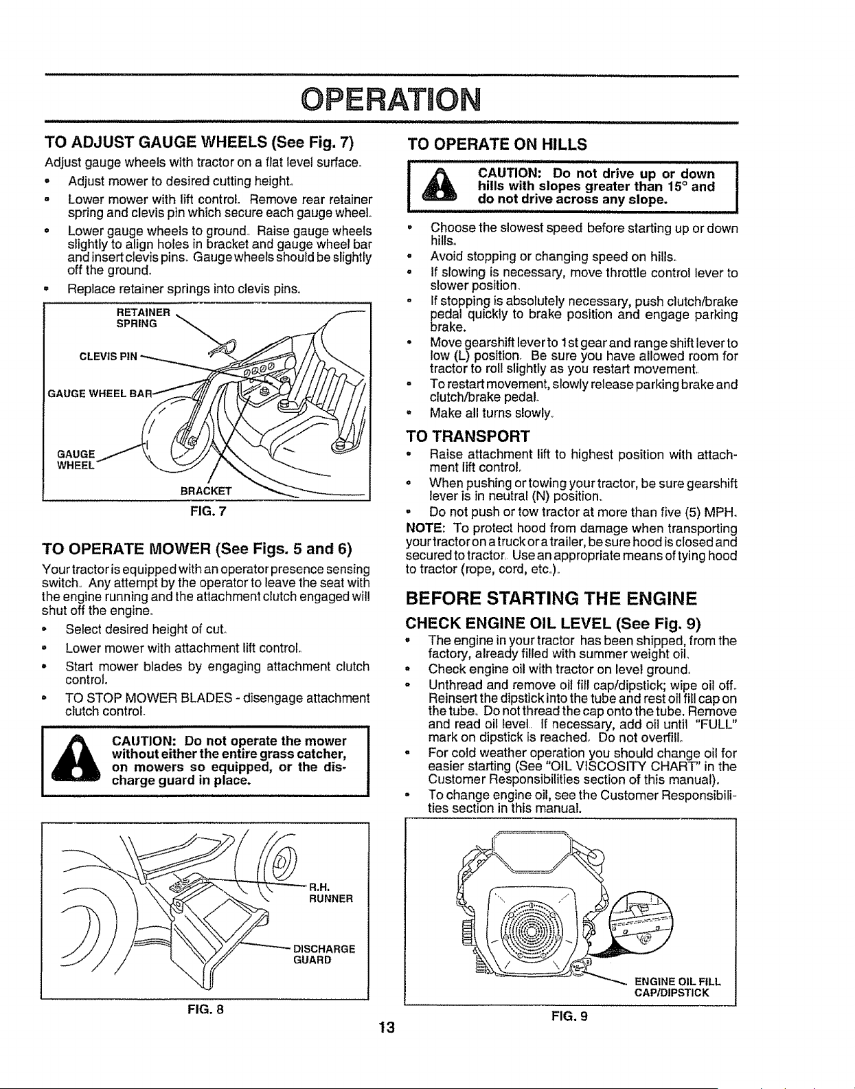
TO ADJUST GAUGE WHEELS (See Fig. 7)
Adjust gauge wheels with tractor on a flat level surface°
o Adjust mower to desired cutting height°
- Lower mower with lift control. Remove rear retainer
spring and clevis pin which secure each gauge wheel.
o Lower gauge wheels to ground. Raise gauge wheels
slightly to align holes in bracket and gauge wheel bar
and insert clevis pins° Gaugewheels should be slightly
off the ground°
° Replace retainer springs into clevis pins.
RETAINER
SPRING
CLEVIS PiN
GAUGE WHEEL BA
GAUGE
WHEEL
BRACKET
FIG. 7
TO OPERATE MOWER (See Figs. 5 and 6)
Your tractor is equipped with an operator presence sensing
switch Any attempt by the operator to leave the seat with
the engine running and the attachment clutch engaged will
shut off the engine°
- Select desired height of cut°
- Lower mower with attachment lift control.
° Start mower blades by engaging attachment clutch
control°
° TO STOP MOWER BLADES- disengage attachment
clutch control.
CAUTION: Do not operate the mower
without either the entire grass catcher,
on mowers so equipped, or the dis-
charge guard in place.
TO OPERATE ON HILLS
I _ CAu_oN" Do notdriveup ordown .........J
hills with slopes greater than 15° and
do not drive across...a,nyslope.
• Choose the slowest speed before starting up or down
hills.
° Avoid stopping or changing speed on hills.
° If slowing is necessary, move throttle control lever to
slower position_
- If stopping is absolutely necessary, push clutch/brake
pedal quickly to brake position and engage parking
brake.
• Move gearshift lever to 1st gearand range shift lever to
low (L) position. Be sure you have allowed room for
tractor to roll slightly as you restart movement
° To restart movement, slowly release parking brake and
clutch/brake pedal.
• Make all turns slowly
TO TRANSPORT
° Raise attachment lift to highest position with attach-
ment lift control
o When pushing or towing your tractor, be sure gearshift
lever is in neutral (N) position.
• Do not push or tow tractor at more than five (5) MPH.
NOTE: To protect hood from damage when transporting
your tractor on a truck oratrailer, be sure hood is closed and
secured to tractor. Use an appropriate means oftying hood
to tractor (rope, cord, etc)
BEFORE STARTING THE ENGINE
CHECK ENGINE OIL LEVEL (See Fig. 9)
° The engine in your tractor has been shipped, from the
factory, already filled with summer weight oil
, Check engine oil with tractor on level ground_
° Unthread and remove oiJfill cap/dipstick; wipe oil off°
Reinsert the dipstick into the tube and rest oil fill cap on
thetube. Do notthread thecap ontothe tube. Remove
and read oil level if necessary, add oil until "FULL"
mark on dipstfck is reached° Do not overfill
- For cold weather operation you should change oil for
easier starting (See "OIL VISCOSITY CHART" in the
Customer Responsibilities section of this manual)°
• To change engine oil, see the Customer Responsibili-
ties section in this manual.
RUNNER
DISCHARGE
GUARD
FIG. 8
E.G,.EO,'F,LL
CAP/DIPSTICK
FIG. 9
13
OPERATION
ADD GASOLINE
• Fill fuel tank, Use fresh, clean, regular unleaded
gasoline with a minimum of 87 octane. (Use of leaded
gasoline wil! increase carbon and lead oxide deposits
and reduce valve life). Do not mix oil with gasoline.
Purchase fuel in quantities that can be used within 30
days to assure fuel freshness.
IMPORTANT: WHEN OPERATING IN TEMPERATURES
BELOW 32°F(0°C), USE FRESH, CLEAN WINTER GRADE
GASOLINE TO HELP INSURE GOOD COLD WEATHER
STARTING.
WARNING: Experience indicates that alcohol blended
fuels (called gasohol or using ethanol or methanol) can
attract moisture which leads to separation and formation of
acids during storage. Acidic gas car] damage the fuel
system of an engine while in storage. To avoid engine
problems, the fuel system should be emptied before stor-
age of 30 days or longer. Drain the gas tank, start the
engine and let it run until the fuel lines and carburetor are
empty. Use fresh fuel next season. See Storage Instruc-
tions for' additional information. Never use engine or
carburetor cleaner products in the fuel tank or permanent
damage may occur.
'"& CAUTION; Fill to bottom of gas tank
fiilerneck. Do notoveffill. Wipeoffany
spilled oil or fuel. Do not store, spill or
use gasoline near an open flame.
TO START ENGINE (See Fig. 6)
This engine on this product is designed for maximum
performance and Fifeif operated with the choke (!\l) fully
open and the throttle control in the fast (,_) position_To
open the choke fully requires an engine warm-up pedod of
several seconds to several minutes, depending on the
temperature°
After starting the engine, first open the choke slowly until
the engine just begins to run smoothly. Then open the
choke in small steps, allowing the engine to accept small
changes in speed and load, until the choke is fully open..
During engine warm-up, the equipment can be operated.
When starting engine for the first time or if engine has run
out of fuel, it will take extra cranking time to move fuel from
the tank to the engine.
• Depress clutch/brake pedal and set parking brake.
• Place gearshift lever in neutral (N) position.
• Move attachment clutch to "DISENGAGED" position°
• Pull choke control out to choke (N) position for cold
engine start. For warm engine start do not use choke
control.
• Move throttle control to midway between fast ('_) and
slow (._) positions.
- Insert key into ignitionandturn keyclockwise to"START"
position and release key as soon as engine starts. Do
not run starter continuously for more than fifteen
seconds per minute. If engine does not start after
several attempts, move throttle control to fast (,_)
position, wait a few minutes and try again.
• When engine starts, slowly push choke control in.
• Move throttle control to fast (._) position.
• Allow engine to warm up for a few minutes before
engaging drive or attachments.
NOTE= If at a high altitude (above 3000 feet) or in cold
temperatures (below 32°F), the carburetor fuel mixture
may need to be adjusted for best engine performance. See
,,TO ADJUST CARBURETOR" in the Service and Adjust-
ments section of this manual.
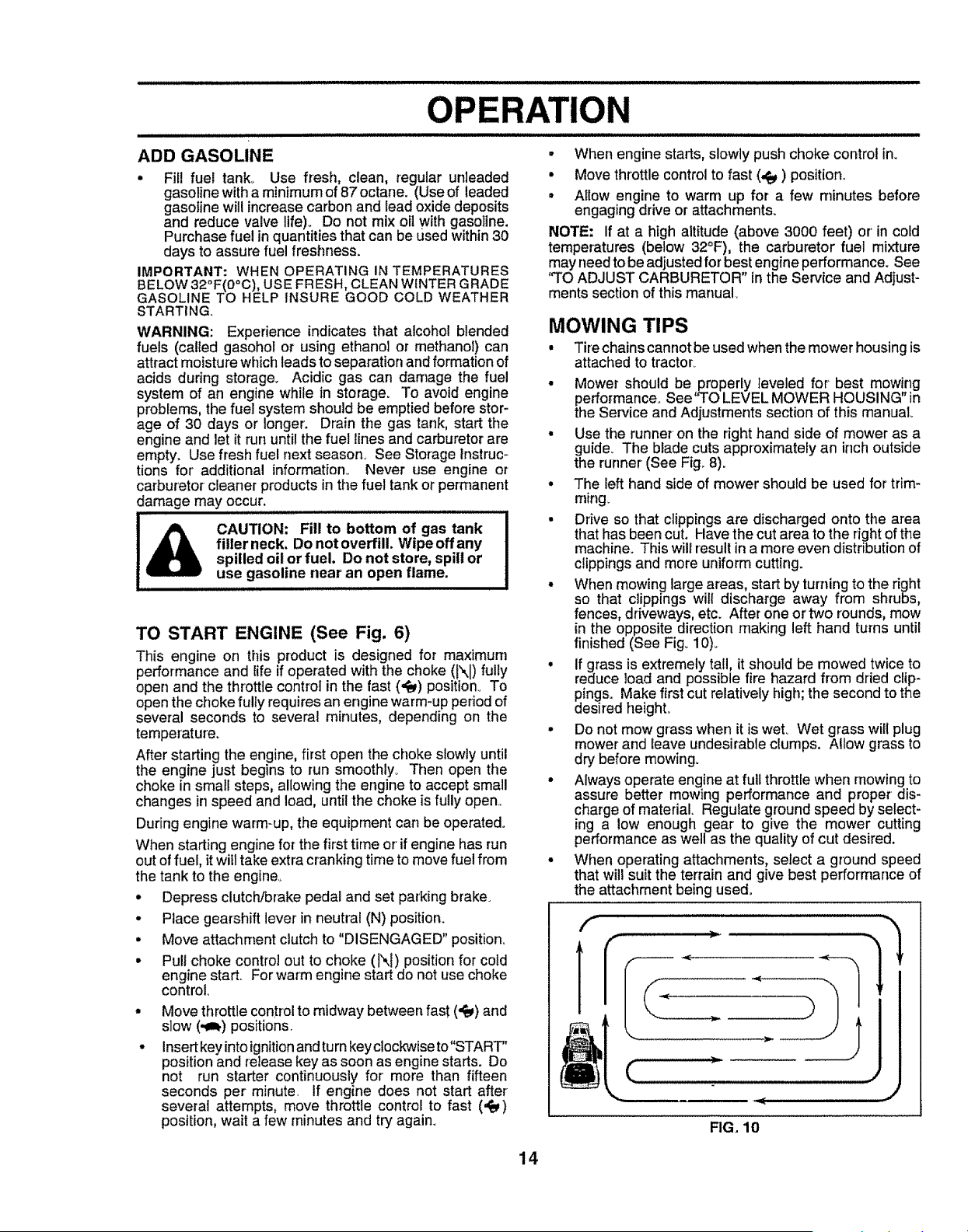
MOWING TIPS
• Tirechainscannot be used when the mower housing is
attached to tractor.
• Mower should be properly leveled for' best mowing
performance_ See'q"O LEVEL MOWER HOUSING" in
the Service and Adjustments section of this manual
• Use the runner on the right hand side of mower as a
guide_ The blade cuts approximately an inch outside
the runner (See Fig° 8).
= The left hand side of mower should be used for trim-
ming_
• Drive so that clippings are discharged onto the area
that has been cut. Have the cut area to the fight of the
machine. This will result in a more even distribution of
clippings and more uniformcutting.
• When mowing large areas, start by turning to the right
so that clippings will discharge away from shrubs,
fences, driveways, etc. After one or two rounds, mow
in the opposite direction making left hand turns until
finished (See Fig_10)_
• if grass is extremely tall, it should be mowed twice to
reduce load and possible fire hazard from dried clip-
pings. Make first cut relatively high; the second to the
desired heighL
= Do not mow grass when it is wet_ Wet grass will plug
mower and leave undesirable clumps. Allow grass to
dry before mowing.
• Always operate engine at full throttle when mowing to
assure better mowing performance and proper dis-
charge of material Regulate ground speed by select-
ing a low enough gear to give the mower cutting
performance as well as the quality of cut desired.
• When operating attachments, select a ground speed
that will suit the terrain and give best performance of
the attachment being used.
FIG. 10
14
CUSTOMER RESPONSmBIUTIES
F,LL,NDATES
AS YOU COMPLETE
REGULAR SERV1CE _'___'SERVICE DATES
CheckBrakeOpe,atfon .......................i _
Sharpen/Replace Mower Blades
Lubrication Chart
Check Tire Pressure
T Check for Loose Fasteners
c
T Check Battery kevel/Rech,ar,g_......
0 Clean Battery and Terminals
R Check Transaxle Cooling
Adjust Blade Bait(s) Tension
Adjust Motion Drive Belt(s) Tension
Check Engine Oil Level ............
Change Engine Oil
!= Clean Air Filter
N Clean Air Screen .....
!G Inspect Mufffer/SparkArrester
I Replace Oil Filter (If equipped)
,/ V'
v'
v', e,'
................... n.,-
v"
_,"e
Ks
v"2
'" v,,,,,,
I
N O,eanEn0,oe 9'o,,ogF,ns........ii...............,"i,,ii"",,. ..... .............
Replace Spark Plug _#' 6#4
Replace Air Filter Paper Cartridge _2
Replace Fuel Filter
I - Change mere o|ten when operaling under a heavy toad or in hlgh ambient temperatures 5 - f_ equipped with adjustable system..
2 ,,Servicemoreoftenwhenoperating inditty or dusty conditions
3 - If equippedwith oilfiller, changeoil every50 hours
4 -RepIace bladesmore oftenwhenmowing in sandysoil
S - Not required if equipped with matr_lenance4ree ba_ler,j
7 _Tighten front axle pivot boil to 35 It -lbs maximum
Do not ovettighlen
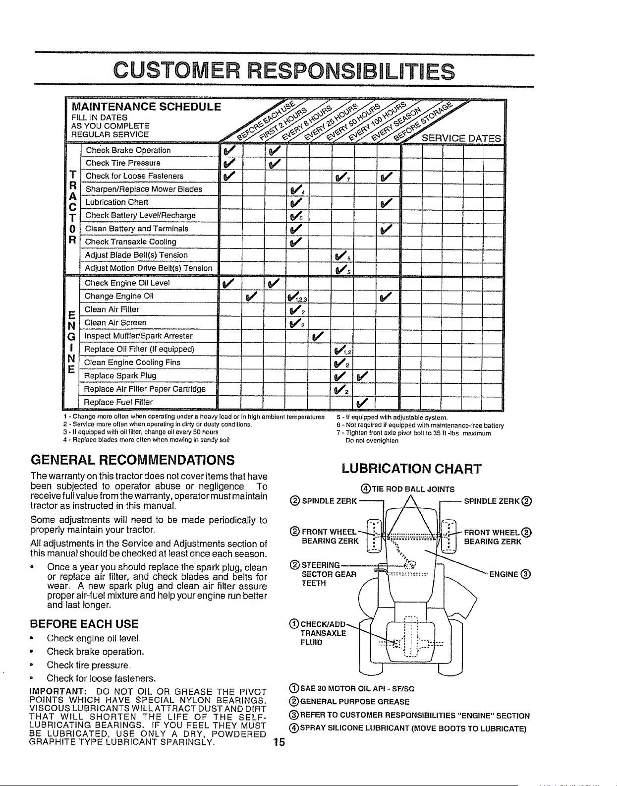
GENERAL RECOMMENDATIONS
The warranty on this tractor does not cover items that have
been subjected to operator abuse or negligence., To
receive full value from the warranty, operator must maintain
tractor as instructed in this manual
Some adjustments will need to be made periodically to
properly maintain your tractor,,
All adjustments in the Service and Adjustments section of
this manual should be checked at least once each season,,
Once a year you should replace the spark plug, clean
or replace air filter, and check blades and belts for
wear. A new spark plug and clean air filter assure
proper air4uel mixture and help your engine run better
and last longer.
BEFORE EACH USE
• Check engine oi! level,
• Check brake operation.
- Check tire pressure,,
• Check for loose fasteners.
IMPORTANT: DO NOT OIL OR GREASE THE PIVOT
POINTS WHICH HAVE SPECIAL NYLON BEARINGS.
VISCOUS LUBRICANTS WtLL ATTRACT DUST AND DIRT
THAT WILL SHORTEN THE LIFE OF THE SELF-
LUBRICATING BEARINGS. IF YOU FEEL THEY MUST
BE LUBRICATED, USE ONLY A DRY, POWDERED
GRAPHITE TYPE LUBRICANT SPARINGLY.
LUBRICATION CHART
(_)']'IE ROD BALL JOINTS
(_) SPINDLE ZERK __ t_ SPINDLE ZERK (_)
(_) STEERIr
SECTOR GEAR ENGINE (_
TEETH
O
TRANSAXLE
FLUID
'15
(_)SAE 30 MOTOR OIL AP! - SFISG
(_)GENERAL PURPOSE GREASE
(_)REFER TO CUSTOMER RESPONSIBILITIES "ENGINE" SECTION
(_)SPRAY SILICONE LUBRICANT (MOVE BOOTS TO LUBRICATE)
C RESPONSIBI
TRACTOR
Always observe safety rules when performing any mainte-
nance.
BRAKE OPERATION
o
e
o
If tractor requires more than six (6) feet stopping distance
at high speed in highest gear, then brake must be adjusted.
(See 'q'O ADJUST BRAKE" in the Service and Adjust-
ments section of this manual).
TIRES
• Maintain proper air pressure in all tires (See "PROD-
UCT SPECIFICATIONS" on page 3 of this manual).
• Keeptiresfree of gasoline, oil,or insectcontrol chemi-
cals which can harm rubber:
• Avoid stumps, stones, deep ruts, sharp objects and
other hazards that may cause tire damage.
BLADE CARE
For best results mower blades must be kept sharp,. Re-
place bent or damaged blades.
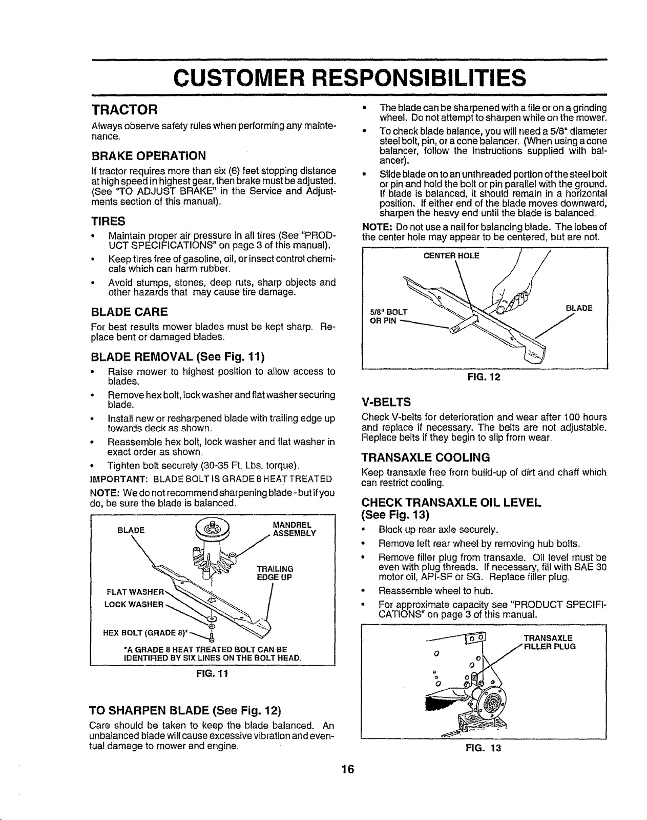
BLADE REMOVAL (See Fig. 11)
• Raise mower to highest position to allow access to
blades.
Remove hex bolt, lock washerand fiat washer securing
blade,
Install new or resharpened blade with trailing edge up
towards deck as shown.
Reassemble hex bolt, lock washer and flat washer in
exact order as shown.
• Tighten bolt securely (30-35 FtoLbs. torque),
IMPORTANT: BLADE BOLT IS GRADE 8 HEATTREATED
NOTE: We do not recommend sharpening btade- but ifyou
do, be sure the blade is balanced.
"_ MANDREL
BLADE _ ASSEMBLY
_" __TRAILING
EDGE UP
FLAT WASHER',, _ /
.ExBoLT(G.ADE
"A GRADE 8 HEAT TREATED BOLT CAN BE
,DEN.nEDBYs,xUNESO.THEBOLT.EAO.
FIG. 11
TO SHARPEN BLADE (See Fig. 12)
Care should be taken to keep the blade balanced° An
unbalanced blade will cause excessive vibration and even-
tual damage to mower and engine.
• The blade can be sharpened with a file or on a grinding
wheel, Do not attempt to sharpen while on the mower.
• To check blade balance, you wilt need a 5/8" diameter
steel bolt, pin, or a cone balancer. (When using a cone
balancer, follow the instructions supplied with bal-
ancer)_
• Slide blade on to an unthreaded portion of the steel bolt
or pin and hold the bolt or pin parallel with the ground.
If blade is balanced, it should remain in a horizontal
position, if either end of the blade moves downward,
sharpen the heavy end until the blade is balance&
NOTE: Do not use a nail for' balancing blade° The lobes of
the center hole may appear to be centered, but are not.
CENTER HOLE
5/8" BOLT
OR PIN
BLADE
FIG. 12
V-BELTS
Check V-belts for deterioration and wear' after 100 hours
and replace if necessary., The belts are not adjustable.
Replace belts if they begin to slip from wear.
TRANSAXLE COOLING
Keep transaxle free from buiid-up of dirt and chaff which
can restrict cooling.
CHECK TRANSAXLE OIL LEVEL
(See Fig, 13)
° Block up rear' axle securely.
• Remove left rear wheel by removing hub bolts_
• Remove filler plug from transaxle. Oil level must be
even with plug threads, if necessary, fill with SAE 30
motor oil, API-SF or SG. Replace filler plug_
• Reassemble wheel to hub.
• For approximate capacity see "PRODUCT SPECIFI-
CATIONS" on page 3 of this manual°
O (3
o
I
FIG. 13
TRANSAXLE
16
CUSTOMER
i ..................
BATTERY
Your tractor has a battery charging system which is suffi-
cient for norma_ use However, periodic charging of the
battery with an automotive charger will extend its life.
= Keep battery and terminals Clean
= Keep battery bolts tight
° Keep small vent holes open
• Recharge at 6-10 amperes for 1 hour
TO CLEAN BATTERY AND TERMINALS
Corrosion and dirt on the battery and terminals can cause
the battery to "leal¢' power°
° Remove terminal guard°
- Disconnect BLACK battery cable first then RED bat-
ter] cable and remove battery from tractor.
° Rinse the battery with plain water and dry°
° Clean terminals and battery cable ends with wire brush
until bright
• Coat terminals with grease or petroleum jelly
° Reinstall battery (See "CONNECT BATTERY" in the
Assembly section of this manual)
ENGINE
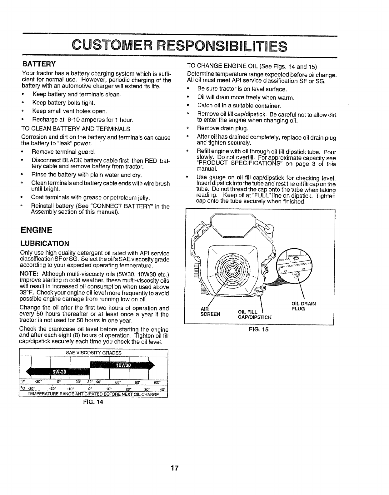
LUBRICATION
Only use high quality detergent oil rated with API service
classification SF or SG Select the oil's SAE viscosity grade
according to your expected operating temperature
NOTE: Although multi-viscosity oils (5W30, 10W30 etc)
improvestarting incold weather, these multi viscosity oils
will result in increased oil consumption when used above
32°F Check your engine oil levelmore frequently to avoid
possible engine damage from running low on oil
Change the oil after the first two hours of operation and
every 50 hours thereafter or at least once a year if the
tractor is not used for 50 hours in one yearn
Check the crankcase oil level before starting the engine
and after each eight (8) hours of operation Tighten oil fill
cap/dipstick securely each time you check the oil level
SAEVlSCOSfTYGRADES......
I
-20 ° O" 30" 32= 40 _ 60 _ 80' I00 _ .......
.......TEMPERATURE RANGE ANTICIPATEDBEFORE NEXTOILCHANGE
FIG. !4
,1111i ............
RESPONSmBmLJTmE$
HIll i iiii iiii i ii
TO CHANGE ENGINE OIL (See Figs° 14 and 15)
Determine temperature range expected before oil change°
All oil must meet API service classification SF or SG
° Be sure tractor is on Ievel surface°
° Oi! will drain more freely when warm°
= Catch oil in a suitable container
° Remove oil fill cap/dipstick Be careful not to allow dirt
to enter the engine when changing oil
= Remove drain plug
° After oil has drained completely, replace oil drain plug
and tighten securely
o Refill engine with oil through oil fill dipstick tube Pour
slowly Do not overfill For approximate capac ty see
"PRODUCT SPECIFICATIONS" on page 3 of this
manual
Use gauge on oil fill cap/dipstick for checking level
insertdipstick intothe tube and rest the oil fill cap on the
tube Do not thread the cap onto the tube when taking
reading° Keep oil at 'FULL' line on dipstick. Tighten
cap onto the tube securely when finished
AIR
SCREEN
OIL FILL i
CAP/DIPSTICK
OIL DRAIN
PLUG
FIG. 15
17
CUSTOMER
................................ , ,, ,, ,, ,,,
CLEAN AIR SCREEN (See Fig. 15)
Air screen must be kept free of dirt and chaff to prevent
engine damage from overheating_ Clean with a wire brush
or' compressed air to remove dirt and stubborn dried gum
fibers..
CLEAN AIR INTAKE/COOLING AREAS
To insure proper cooling, make sure the grass screen,
cooling fins, and other external surfaces of the engine are
kept clean at all times.
Every 100 hours of operation (more often under extremely
dusty, dirty conditions), remove the blower housing and
other cooling shrouds_Clean the cooling fins and external
surfaces as necessary. Make sure the cooling shrouds are
reinstalled,.
NOTE: Operating the engine with a blocked grass screen,
dirty or plugged cooling fins, and!or cooling shrouds re-
moved will cause engine damage due to overheating_
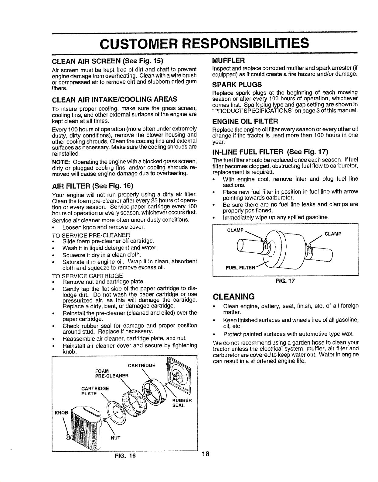
AIR FILTER (See Fig. 16)
Your engine will not run properly using a dirty air filter°
Clean the foam pre-cleaner after every 25 hours of opera-
tion or every season° Service paper cartridge every 100
hours of operation or' every season, whichever occurs first.
Service air cleaner more often under dusty conditions.
• Loosen knob and remove coverL
TO SERVICE PRE-CLEANER
• Slide foam pre-cleaner off cartridge.
• Wash it in liquid detergent and water
• Squeeze it dry in a clean cloth.
• Saturate it in engine oil. Wrap it in clean, absorbent
cloth and squeeze to remove excess oil.
TO SERVICE CARTRIDGE
• Remove nut and cartridge plate..
• Gently tap the flat side of the paper cartridge to dis-
MUFFLER
Inspect and replace corroded muffler' and spark arrester (if
equipped) as it could create a fire hazard and/or damage.
SPARK PLUGS
Replace spark plugs at the beginning of each mowing
season or after every i00 hours of operation, whichever
comes first. Spark plug type and gap setting are shown in
"PRODUCT SPECIFICATIONS" on page 3 of this manual.
ENGINE OIL FILTER
Replace tile engine oil filter ever,.#season or every otheroil
change if the tractor is used more than 100 hours in one
yearL
IN-LINE FUEL FILTER (See Fig. 17)
The fuel filter should be replacedonce each season. If fuel
filter becomesclogged, obstructingfuel flow to carburetor,
replacement is required.
• With engine cool, remove filter and plug fuel line
sections_
° Place new fuel filter in position in fuel line with arrow
pointing towards carburetor.
• Be sure there are no fuel line leaks and clamps are
properly positioned_
• Immediately wipe up any spiffed gasoline.
FIG. 17
lodge dirL Do not wash the paper cartridge or' use
pressurized air, as this wil! damage the cartridge,,
Replace a dirty, bent, or damaged cartridge_
• Reinstall the pre-cleaner (cleaned and oiled) over the
paper cartridge.
• Check rubber seat for damage and proper position
around stud_ Replace if necessary.
• Reassemble air cleaner, cartridge plate, and nuL
• Reinstall air cleaner cover and secure by tightening
knob.
CARTRIDGE
FOAM
PRE*CLEANER
CARTRIDGE
PLATE "X,
RUBBER
SEAL
NUT
CLEANING
* Clean engine, battery, seat, finish, etc_of all foreign
matter.
• Keep finished surfaces and wheels free of all gasoline,
oil, etc.
• Protect painted surfaces with automotive type wax_
We do not recommend using a garden hose to clean your
tractor unless the electrical system, muffler, air filter and
carburetor are covered to keep water out. Water in engine
can result in a shortened engine lifeo
FIG. 16 18
SERVmCE AND ADJUSTMENTS
,,,, ,,,,,,,,,, ,,
CAUTION: BEFORE PERFORMING ANY SERVICE OR ADJUSTMENTS:
= Depress clutch/brake pedal fully and set parking brake.
,, Place gearshift lever in neutral (N) position.
o Place attachment clutch in "DISENGAGED" position.
• Turn ignition key "OFF" and remove key.
° Make sure the blades and all moving parts have completely stopped.
°
Disconnect spark plug wire from spark plug and place wire where it cannot come in contact
with plug_
TRACTOR
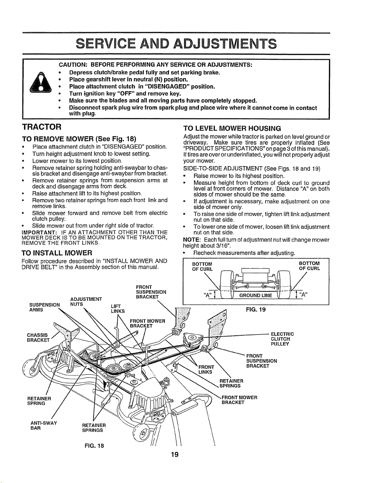
TO REMOVE MOWER (See Fig, 18)
• Place attachment clutch in "DISENGAGED" position,
• Turn height adjustment knob to lowest setting,
o Lower mower to its lowest position.
° Remove retainer spring holding anti-swaybar to chas-
sis bracket and disengage anti-swaybar from bracket°
= Remove retainer springs from suspension arms at
deck and disengage arms from deck_
° Raise attachment liftto its highest position_
• Remove two retainer springs from each front link and
remove linksr
= Slide mower forward and remove belt from electric
clutch pulley,
. Slide mower out from under right side of tractor,
IMPORTANT; 1F AN ATTACHMENT OTHER THAN THE
MOWER DECK IS TO BE MOUNTED ON THE TRACTOR,
REMOVE THE FRONT LINKS.
TO INSTALL MOWER
Follow procedure described in "INSTALL MOWER AND
DRIVE BELT" in the Assembly section of this manual.
ADJUSTMENT
SUSPENSION NUTS LIFT
ARMS LINKS
FRONT
SUSPENSION
BRACKET
\
FRONT MOWER
BRACKET
TO LEVEL MOWER HOUSING
Adjust the mower while tractor is parked on level ground or
driveway. Make sure tires are properly inflated (See
"PRODUCT SPECIFICATIONS" on page 3 of this manual).
If tires are ever or underinflated, you will not properly adjust
your mower,
SIDE-TO-SIDE ADJUSTMENT (See Figso18 and 19)
• Raise mower to its highest position.
° Measure height from bottom of deck curl to ground
level at front corners of mower_ Distance 'W' on both
sides of mower should be the same,
° If adjustment is necessary, make adjustment on one
side of mower only.
= To raise one side of mower, tighten lift link adjustment
nut on that side.
° To lower one side of mower, loosen lift link adjustment
nut on that side,
NOTE: Each full turn of adjustment nut wilt change mower
height about 3/I6"o
° Recheck measurements after adjusting°
BOTTOM BOTTOM
OF CURL OF CURL
FIG, 19
CHASSIS
ELECTRIC
CLUTCH
PULLEY
FRONT
SUSPENSION
BRACKET
RETAINER
SPRING
RETAINER
SPRINGS
BRACKET
ANTI-SWAY RETAINER
BAR SPRINGS
FIG. 18
19
ICE AND ADJUSTMENTS
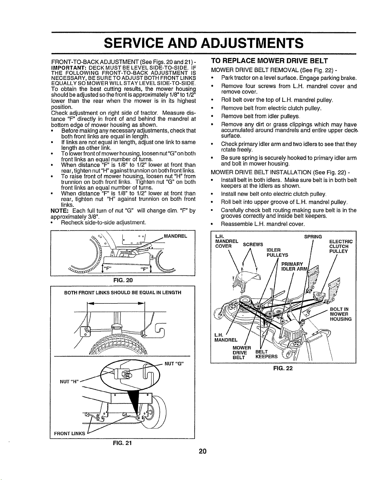
FRONT-TO-BACK ADJUSTMENT (See Figs. 20 and 21) -
IMPORTANT: DECK MUST BE LEVEL SIDE-TO-SIDE.. IF
THE FOLLOWING FRONT-TO-BACK ADJUSTMENT IS
NECESSARY, BE SURETO ADJUST BOTHFRONT LINKS
EQUALLYSO MOWER WILL STAY LEVEL SIDE-TO-SIDEo
TO obtain the best cutting results, the mower housing
should be adjusted so the front is approximately 1/8" to 1/2"
lower than the rear when the mower is in its highest
position_
Check adjustment on right side of tractor. Measure dis-
tance "F" directly in front of and behind the mandrel at
bottom edge of mower housing as shown_
Before making any necessary adjustments, check that
both front linksare equal in length.
• If links are not equal in length, adjust one link to same
length as other link.
- To lower front of mower housing, loosen nut"G" on both
front links an equal number of turns°
• When distance "F" is t/8" to 1/2" lower at front than
rear, tighten nut"H" against trunnion on both front links.
° To raise front of mower housing, loosen nut "H" from
trunnion on both front links. Tighten nut "G" on both
front links an equal number of turns.
• When distance "F" is 1/8" to 1/2" lower at front than
rear, tighten nut "H" against trunnion on both front
links.
NOTE: Each fult turn of nut "G" will change dim, "F" by
approximately 3/8".
• Recheck side-to-side adjustmenL
LlUJUJIIIJIL,UlJJlJJlJJII II II I I I I
TO REPLACE MOWER DRIVE BELT
MOWER DRIVE BELT REMOVAL (Se e Fig. 22)
° Park tractor on a level surface, Engage parking brake.
• Remove four' screws from L.H_ mandrel cover' and
remove cover.
• Roll belt over'the top of LH_ mandrel pulley.
• Remove belt from electric clutch pulley.
• Remove belt from idler pulleys,
• Remove any dirt or grass clippings which may have
accumulated around mandrels and entire upper deck_
surface°
° Check primary idler arm and two idlers to see that they
rotate freely_
• Be sure spring is securely hooked to primary idler arm
and bolt in mower housing,
MOWER DRIVE BELT INSTALLATION (See Fig. 22) -
• install bert in both idlers_ Make sure belt is in both belt
keepers at the idlers as shown.
° Install new belt onto electric clutch pulley.
° Roll belt into upper groove of L.H_mandrel putiey,
• Carefully check belt routing making sure belt is in the
grooves correctly and inside belt keepers.
• Reassemble L.H_ mandrei coven
MANDREL
"F" F"
FIG. 20
BOTH FRONT LINKS SHOULD BE EQUAL IN LENGTH
NUT "G"
NUT"H'
FRONT LINKS
L.H,
MANDREL
COVER
MANDREL
SCREWS
MOWER
DRIVE
BELT
SPRING
IDLER
PULLEYS
PRIMARY
IDLER ARM
BELT
KEEPERS
FIG, 22
ELECTRIC
CLUTCH
PULLEY
BOLT IN
MOWER
HOUSING
FIG, 21
20
SERVmCE AND ADJUSTMENTS
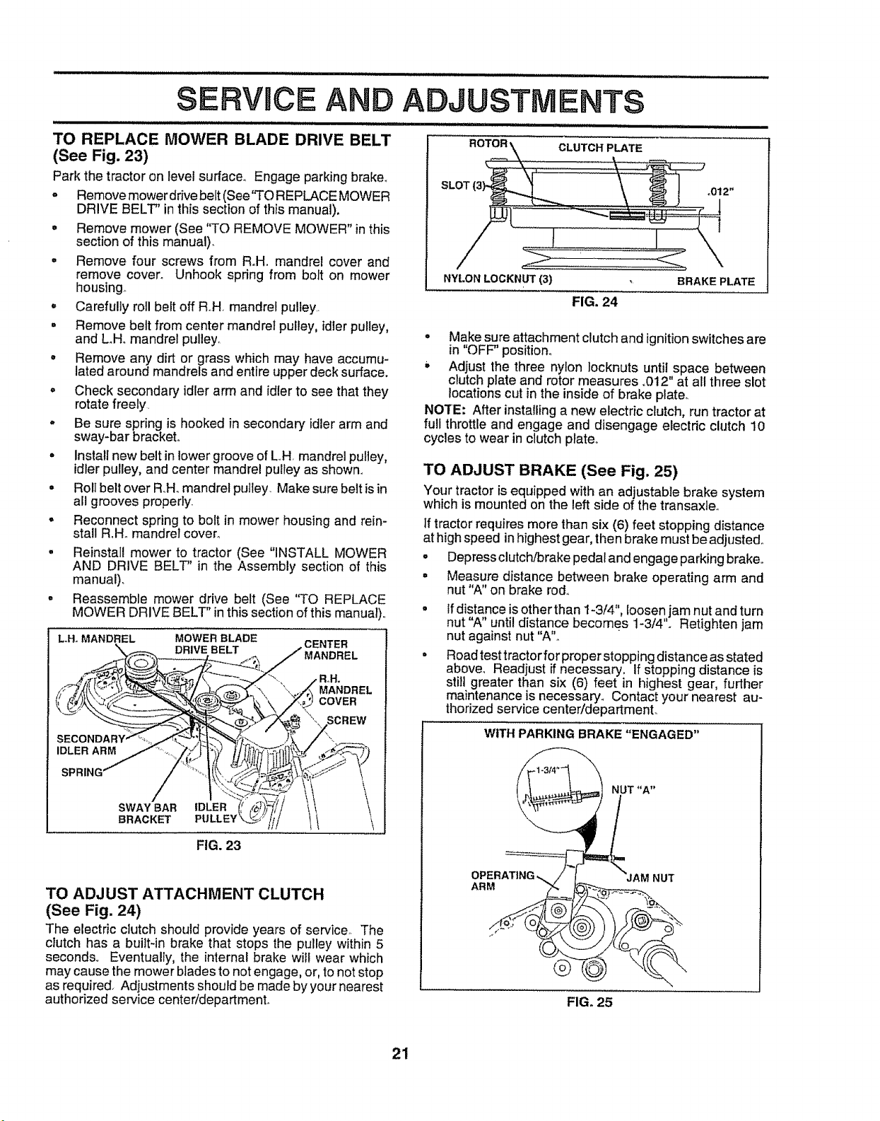
TO REPLACE MOWER BLADE DRIVE BELT
(See Fig. 23)
Park the tractor on level surface° Engage parking brake°
= Remove mower drive belt (See'70 REPLACE MOWER
DRIVE BELT" in this section of this manual),
= Remove mower (See 'q'O REMOVE MOWER" in this
section of this manual).
o Remove four screws from R,H. mandrel cover and
remove cover° Unhook spring from bolt on mower
housing°
- Carefully roll belt off R.H, mandrel pulley,
° Remove belt from center mandrel pulley, idler pulley,
and LH_ mandrel pulley.
. Remove any dirt or grass which may have accumu-
lated around mandrels and entire upper deck surface.
• Check secondary idler arm and idler to see that they
rotate freely.
o Be sure spring is hooked in secondary idler arm and
sway-bar bracket,.
. Install new belt in lower groove of L.H. mandrel pulley,
idlerpulley, and center mandrel pulley as shown°
• Roll belt over R,Homandrel pulley. Make sure belt is in
all grooves property.
° Reconnect spring to bolt in mower housing and rein-
stall Roll. mandrel cover°
= Reinstall mower to tractor (See "INSTALL MOWER
NYLON LOCKNUT(3)
FIG. 24
BRAKE PLATE
° Make sure attachment clutch and ignitionswitches are
in "OFF" position°
Adjust the three nylon locknuts until space between
clutch plate and rotor measures .012" at all three slot
locations cut in the inside of brake platen
NOTE: After installinga new electric clutch, run tractor at
full throttle and engage and disengage e_ectdc clutch 10
cycles to wear in clutch plate°
TO ADJUST BRAKE (See Fig, 25)
Your tractor isequipped with an adjustable brake system
which is mounted on the left side of the transaxle.
If tractor requires more than six (6) feet stopping distance
at high speed in highest gear, then brake must be adjusted,.
• Depress clutch/brake pedal and engage parking brake°
AND DRIVE BELT" in the Assembly section of this
manual)_
Reassemble mower drive belt (See "TO REPLACE
MOWER DRIVE BELT" inthis section of this manual),.
LHo MANDREL MOWER BLADE
CENTER
DRIVE BELT MANDREL
MANDREL
COVER
IDLER ARM
SPRING'
SWAY BAR IDLER i
BRACKET PULLEY
FIG. 23
°
°
TO ADJUST ATTACHMENT CLUTCH
(See Fig. 24)
The electric clutch should provide years of service.. The
clutch has a built-in brake that stops the pulley within 5
seconds.. Eventually, the internal brake witl wear which
may cause the mower blades to not engage, or, to not stop
as required_ Adjustments should be made by your nearest
authorized service center/department.
Measure distance between brake operating arm and
nut "A" on brake rod.,
Ifdistance is other than I-3/4", Ioosen jam nut and turn
nut "A" until distance becomes 1-3/4"o Retighten jam
nut against nut "A"_
Road test tractor for proper stopping dista rice as stated
above° Readjust if necessary, If stopping distance is
still greater than six (6) feet in highest gear, further
maintenance is necessary_ Contact your nearest au-
thorized service center/department_
WITH PARKING BRAKE "ENGAGED"
NUT "A"
ARM
AM NUT
®
FIG. 25
21
Ikll II IIll
VICE AND ADJUSTMENTS
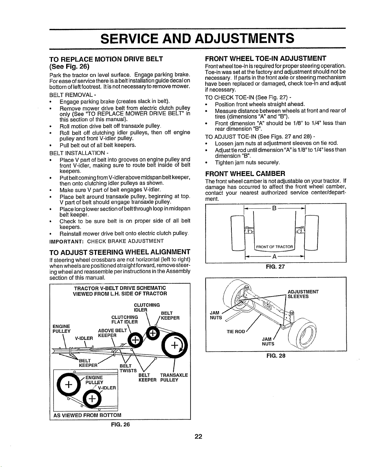
TO REPLACE MOTION DRIVE BELT
(See Fig. 26)
Park the tractor on level surface_ Engage parking brake_
For ease ofservice there is a belt installationguide decal on
bottom of left footrest. Itis not necessary to remove mower.
BELT REMOVAL -
° Engage parking brake (creates slack in belt).
° Remove mower' drive belt from electric clutch pulley
only (See 'q'O REPLACE MOWER DRIVE BELT" in
this section of this manual)°
° Roll motion drive belt off transaxle pulley.
- Rol! belt off clutching idler pulleys, then off engine
pulley and front Widler pulley,
• Pull belt out of all belt keepers.
BELT INSTALLATION -
• Place V part of belt into grooves on engine pulley and
front V-idler, making sure to route bett inside of belt
keepers.
• Put belt coming from V-idler above midspan belt keeper,
then onto clutching idler pulleys as shown.
° Make sure V part of belt engages V-idler..
° Place belt around transaxle pulley, beginning at top..
V part of belt should engage transaxle pulley.,
• Place long lower section of belt through loop in midspan
belt keeper_
• Check to be sure belt is on proper side of all bett
keepers°
• Reinstall mower drive belt onto electric clutch puliey
IMPORTANT; CHECK BRAKE ADJUSTMENT
TO ADJUST STEERING WHEEL ALIGNMENT
If steering wheel crossbars are not horizontal (left to right)
when wheels are positioned straight forward, remove steer-
ing wheel and reassemble per instructionsin the Assembly
section of this manual.
TRACTOR V-BELT DRIVE SCHEMATIC
VIEWED FROM LH. SIDE OF TRACTOR
ENGINE
PULLEY
CLUTCHING
IDLER
CLUTCHING \ BELT
EEPER
FLAT IDLER
ABOVE
V-IDLER
BE_'
KEEPER
BELT
TWISTS
BELT TRANSAXLE
KEEPER PULLEY
AS VIEWED FROM BOTTOM
FRONT WHEEL TOE-IN ADJUSTMENT
Frontwheeltoe-in is required for propersteering operation.
Toe-inwas set at the factory and adjustmentshould not be
necessary.,ff parts inthe front axle or steering mechanism
have been replaced or damaged, check toe-in and adjust
if necessary°
TO CHECK TOE-IN (See Fig° 27) -
• Position front wheels straight ahead.
= Measure distance between wheels at front and rear of
tires (dimensions "A" and "B").
= Front dimension "A" should be 1/8" to 1/4" Bessthan
rear dimension "B'L
TO ADJUST TOE-IN (See Figs. 27 and 28) -
° Loosen jam nuts at adjustment sleeves on tie rod°
° Adjusttie rod until dimension "A" is 1/8"to 1/4" less than
dimension "B"_
o Tighten jam nuts securely.
FRONT WHEEL CAMBER
The front wheel camber is not adjustable on your tractor_ If
damage has occurred to affect the front wheel camber,
contact your nearest authorized service center/depart-
ment.
FIG, 27
JAM
NUTS
ADJUSTMENT
SLEEVES
TIE ROD
NUTS
FIG, 28
FIG, 26
22
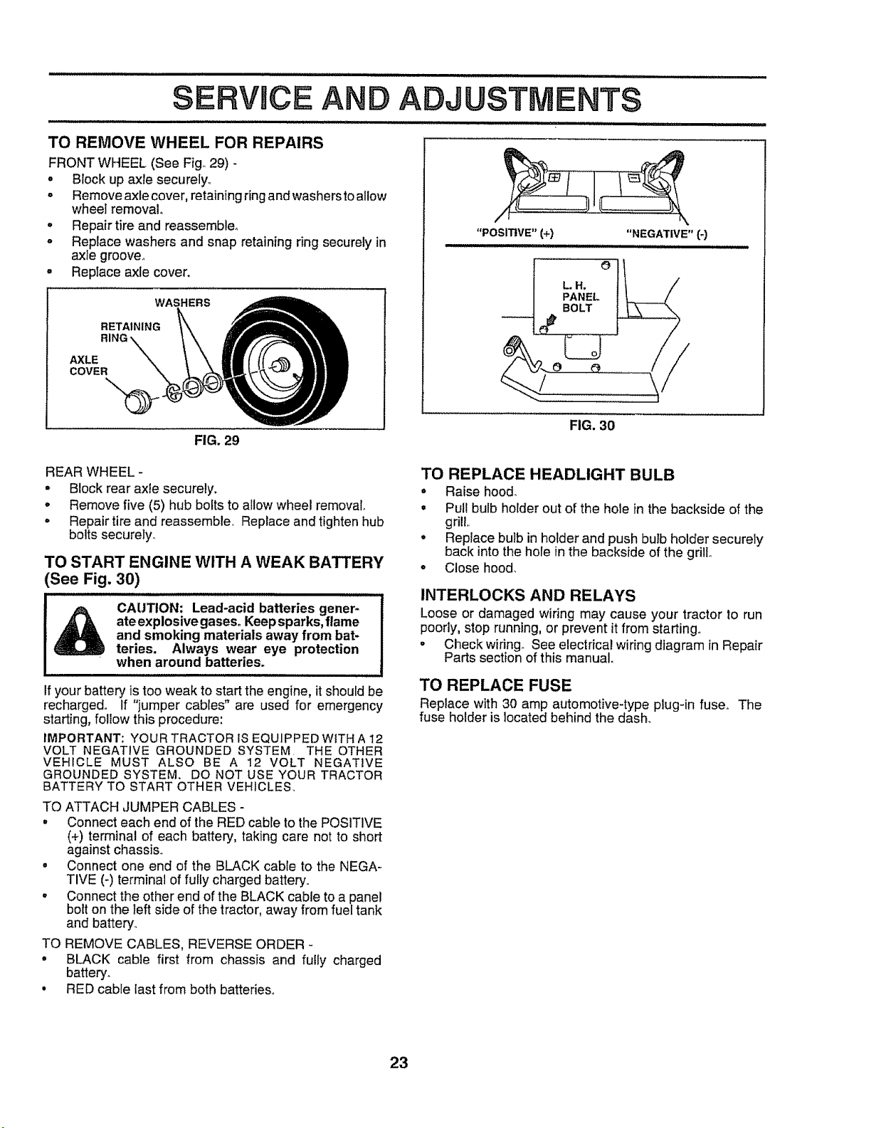
TO REMOVE WHEEL FOR REPAIRS
FRONT WHEEL (See Fig°29)
° Block up axle securely_
o Remove axle cover, retaining ring and washersto ailow
wheel removal.
° Repair tire and reassemble.
o Replace washers and snap retaining ring securely in
axle groove.
• Replace axle cover.
WASHERS
RETAINING
AXLE
COVER
FIG. 29
"POSITIVE" (+) "NEGATIVE" [-)
L.H.
PANEL
BOLT
FIG. 30
REAR WHEEL -
,, Block rear axle securely.
° Remove five (5) hub bolts to allow wheel removal.
° Repair tire and reassemble. Replace and tighten hub
bolts securely.
TO START ENGINE WITH A WEAK BATTERY
(See Fig. 30)
CAUTION: Lead-acid batteries gener_...........t
ateexplosive gases. Keepsparks, flame
and smoking materials away from bat- I
teries. Always wear eye protection |
when around batteries.
II
if your battery is too weak to start the engine, it should be
recharged° If "jumper cables" are used for emergency
starting, follow this procedure:
IMPORTANT: YOUR TRACTOR tS EQUIPPED WiTH A 12
VOLT NEGATIVE GROUNDED SYSTEM THE OTHER
VEHICLE MUST ALSO BE A 12 VOLT NEGATIVE
GROUNDED SYSTEM. DO NOT USE YOUR TRACTOR
BATTERY TO START OTHER VEHICLES
TO ATTACH JUMPER CABLES -
° Connect each end of the RED cable to the POSITIVE
(+) terminal of each battery, taking care not to short
against chassis,.
• Connect one end of the BLACK cable to the NEGA-
TIVE (_) terminal of fully charged battery,
° Connect the other end of the BLACK cable to a panel
bolt on the left side of the tractor, away from fuel tank
and battery
TO REMOVE CABLES, REVERSE ORDER -
° BLACK cable first from chassis and fully charged
battery.
, RED cable last from both batteries,.
TO REPLACE HEADLIGHT BULB
° Raise hoo&
° Pul! bulb holder out of the hole in the backside of the
grill.
° Replace bulb in holder and push bulb holder securely
back into the hole in the backside of the grill
• Close hood.
INTERLOCKS AND RELAYS
Loose or damaged wiring may cause your tractor to run
poorly, stop running, or prevent it from starting.
° Checkwiring_ See electrical wiring diagram in Repair
Parts section of this manual.
TO REPLACE FUSE
Replace with 30 amp automotive-type plug-in fuse, The
fuse holder is located behind the dash.
23
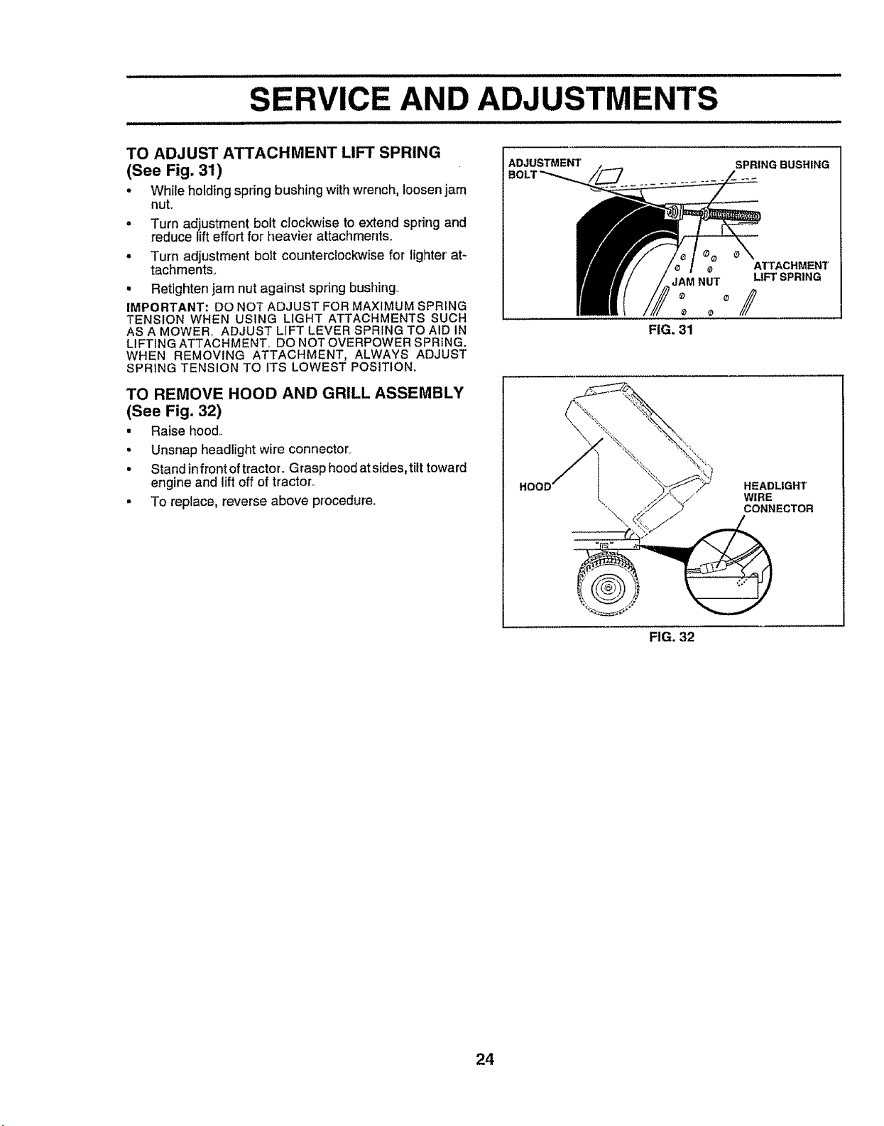
SERVICE AND ADJUSTMENTS
TO ADJUST ATTACHMENT LIFT SPRING
(See Fig. 31)
• While holding spring bushing withwrench,loosen jam
nut.
• Turn adjustment bolt crockwise to extend spring and
reduce lift effort for heavier attachments.,
° Turn adjustment bolt counterclockwise for lighter' at-
tachments°
• Retighten jam nut against spring bushing.
IMPORTANT: DO NOT ADJUST FOR MAXIMUM SPRING
TENSION WHEN USING LIGHT ATTACHMENTS SUCH
AS A MOWER.. ADJUST LIFT LEVER SPRING TO AID IN
LIFTING ATTACHMENT_ DO NOTOVERPOWER SPRING.
WHEN REMOVING ATTACHMENT, ALWAYS ADJUST
SPRING TENSION TO ITS LOWEST POSITION_
TO REMOVE HOOD AND GRILL ASSEMBLY
(See Fig. 32)
• Raise hood,,
• Unsnap headlight wire connector_
• Stand infrontoftractor_ Grasp hood at sides,tilt toward
engine and lift off of tractor.,
• To replace, reverse above procedure.
ADJUSTMENT'
SPRING BUSHING
¢
JAM NUT
ATTACHMENT
LIFT SPRING
°/
FIG. 31
"_" HEADLIGHT
/ WIRE
"_ CONNECTOR
FIG. 32
24
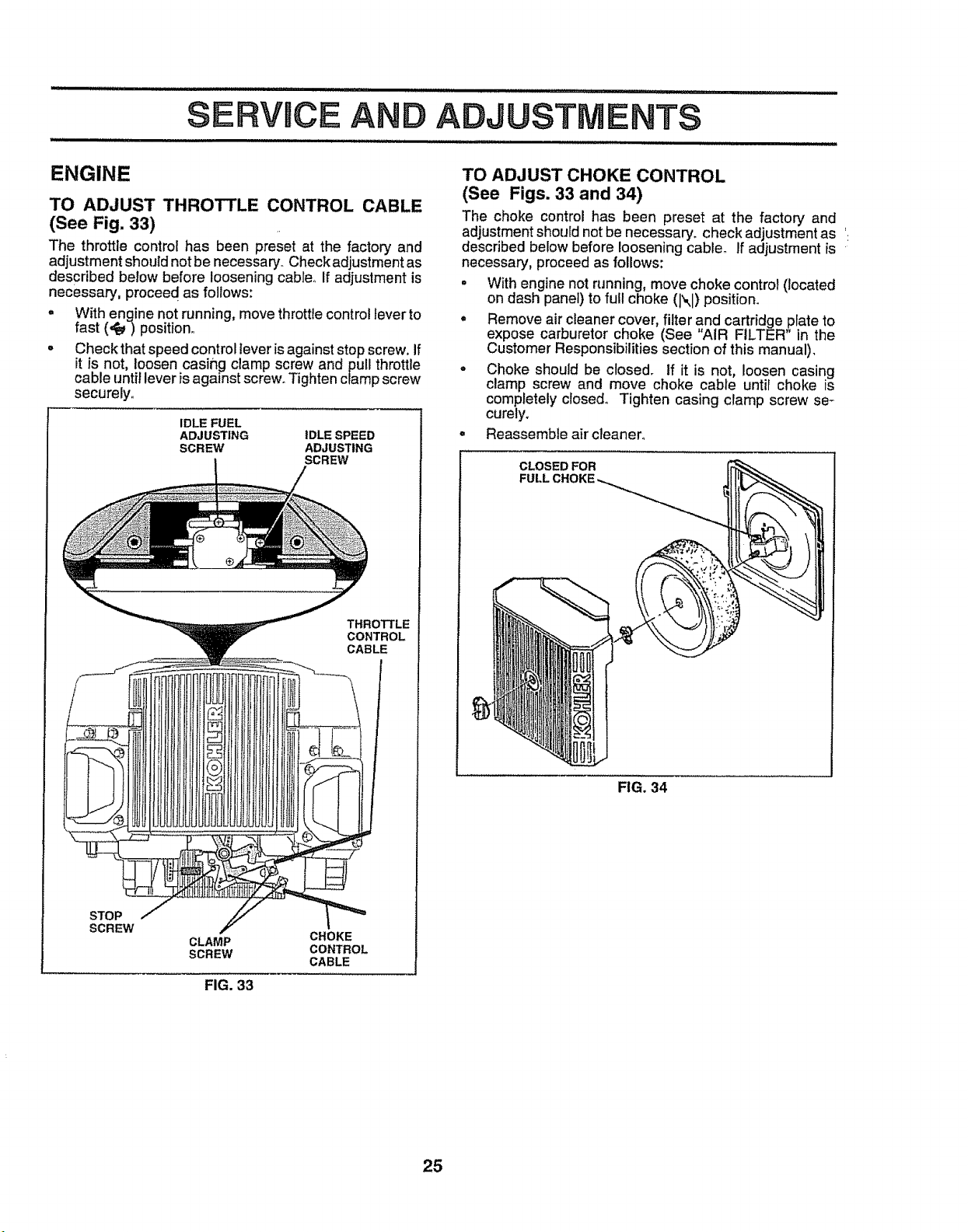
SERVmCE
ADJUSTMENTS
ENGINE
TO ADJUST THROTTLE CONTROL CABLE
(See Fig. 33)
The throttle control has been preset at the factory and
adjustmentshould notbe necessary Check adjustment as
described below before loosening cable. If adjustment is
necessary, proceed as follows:
, With engine not running, move throttle control lever to
fast (,¢e_)position.
- Check that speed control leveris against stop screw. If
it is not, loosen casing clamp screw and pull throttle
cable until lever isagainst screw. Tighten clamp screw
securely.
IDLE FUEL
ADJUSTING
SCREW
IDLE SPEED
ADJUSTING
SCREW
THROTTLE
CONTROL
CABLE
STOP
SCREW
CLAMP
SCREW
CHOKE
CONTROL
CABLE
TO ADJUST CHOKE CONTROL
(See Figs. 33 and 34)
The choke control has been preset at the factory and
adjustment should not be necessary, check adjustment as '.
described below before loosening cable_ If adjustment is
necessary, proceed as follows:
• With engine not running, move choke control (located
on dash panel) to full choke (1",,I)position.
° Remove air cleaner cover, filter and cartridge plate to
expose carburetor choke (See "AIR FILTER" in the
Customer Responsibilities section of this manual).
• Choke should be closed. If it is not, loosen casing
clamp screw and move choke cable until choke is
completely closed. Tighten casing clamp screw se _
curely.
• Reassemble air cleaner.
CLOSED FOR
FULL
FIG. 34
FIG. 33
25
TO ADJUST CARBURETOR (See Fig. 33)
The carburetor has been present at the factory and adjust-
merit should not be necessary_ However, minoradjustment
may be required to compensate for" differences in fuel,
temperature, altitude or load. If the carburetor does need
adjustment, proceed as follows:
In general, turning the adjusting needles in (clockwise)
decreases the supply of fuel to the engine giving a leaner
fuel/air mixture° Turning the adjusting needles out (coun-
terclockwise) increases the supply of fuei to the engine
giving a richer fuel/air mixture.
IMPORTANT; DAMAGE TO THE NEEDLES AND THE
SEATS 1N CARBURETOR MAY RESULT IF SCREW IS
TURNED IN TOO TIGHT.
PRELIMINARY SETTING -
• Be sure you have a clean air filter, and the throttle
control cable is adjusted proper!? (see q'O ADJUST
THROTTLE CONTROL CABLE in the Service and
Adjustments section of this manual),.
= With engine offturn idlefuel adjusting needle in (clock-
wise) closing it finger tight and then turn out (counter-
clockwise) 1 turn.
FINAL SETTING -
= Start engine and allow to warm for five minutes, Make
final adjustments with engine running and shift/motion
control lever in neutral (N) position°
° The high idle is set at the factory and cannot be
adjusted,
• Id!e...speedsetting - With throttle control lever'in slow
(._b) position, engine should idle at 1200 RPM. If
engine idles too slow or fast, turn idlespeed adjusting
screw in or out until correct idle is attained,
• Idle fuel needle settino_- With throttle control lever in
slow (.g_) position, turn idte fuei adjusting needfe in
(clockwise) until engine speed decreases and then
turn out (counterclockwise) approximately 3/4 turn to
obtain the best low speed performance,
• Recheck idle speed_ Readjust if necessary.
ACCELERATION TEST -
• Move throttle control lever from slow (,_) to fast (,_)
position_ If engine hesitates or dies, turn idle fuel
adjusting needle out (counterclockwise) 1/8 turn. Re-
peat test and continue to adjust, if necessary, until
engine accelerates smoothly.
High speed stop isfactory adjusted_ Do not adjust-damage
may result.
IMPORTANT: NEVER TAMPER WITH THE ENGINE
GOVERNOR, WHICH 1S FACTORY SET FOR PROPER
ENGINE SPEED. OVERSPEEDING THE ENGINE ABOVE
THE FACTORY HIGH SPEED SETTING CAN BE
DANGEROUS,. IF YOU THINKTHE ENGINE-GOVERNED
HIGH SPEED NEEDS ADJUSTING, CONTACT YOUR
NEAREST AUTHORIZED SERVICE CENTER/
DEPARTMENT, WHICH HAS PROPER EQUIPMENT AND
EXPERIENCE TO MAKE ANY NECESSARY
ADJUSTMENTS
26
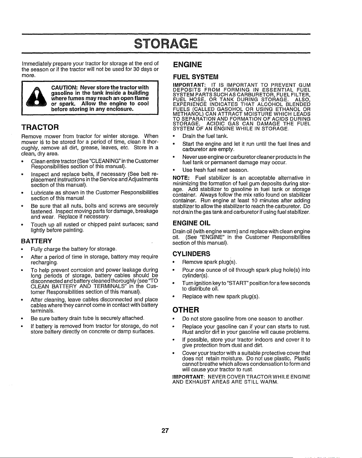
STORAGE
Immediately prepare your tractor for storage at the end of
the season or if the tractor will not be used for 30 days or
more.
I:,.......................
CAUTION: Never store the tractor with I
gasoline in the tank inside a building I
where fumes may reach an open flame i
or spark. Allow the engine to cool I
.............
before storing in any enclosure. I
TRACTOR
Remove mower from tractor for winter storage.. When
mower i_ to be stored for a period of time, clean it thor-
oughly, remove alt dirt, grease, leaves, etco Store in a
clean, dry are&
• Clean entire tractor (See "CLEANING" in the Customer
Responsibilities section of this manual)°
• Inspect and replace belts, if necessary (See belt re-
placement instructions in the Service and Adjustments
section of this manual)_
° Lubricate as shown in the Customer Responsibilities
section of this manual.
° Be sure that all nuts, bolts and screws are securely
fastened, inspect moving parts for damage, breakage
and wear. Replace if necessary.
• Touch up all rusted or chipped paint surfaces; sand
lightly before painting.
BATTERY
° Fully charge the battery for storage_
,, After a period of time in storage, battery may require
recharging,
° To help prevent corrosion and power leakage during
long periods of storage, batter/ cables should be
disconnected and battery cleaned thoroughly (see "TO
CLEAN BATTERY AND TERMINALS Jn the C[ s-
tomer Responsibilities section of this manual).
° After cleaning, leave cables disconnected and place
cables where they cannot come in contact with battery
terminals.
. Be sure battery drain tube is securely attached.
° If battery is removed from tractor for storage, do not
store battery directly on concrete or damp surfaces°
ENGINE
FUEL SYSTEM
IMPORTANT: IT IS IMPORTANT TO PREVENT GUM
DEPOSITS FROM FORMING IN ESSENTIAL FUEL
SYSTEM PARTS SUCH AS CARBURETOR, FUEL FILTER,
FUEL HOSE, OR TANK DURING STORAGE. ALSO,
EXPERIENCE INDICATES THAT ALCOHOL BLENDED
FUELS (CALLED GASOHOL OR USING ETHANOL OR
METHANOL) CAN ATTRACT MOISTURE WHICH LEADS
TO SEPARATION AND FORMATION OF ACIDS DURING
STORAGE. ACIDIC GAS CAN DAMAGE THE FUEL
SYSTEM OF AN ENGINE WHILE IN STORAGE.,
• Drain the fuel tank.
• Start the engine and let it run until the fuel lines and
carburetor are empty.,
• Never use engine or carburetor cleaner products inthe
fuel tank or permanent damage may occur.
° Use fresh fuel next season°
NOTE: Fuel stabilizer is an acceptable alternative in
minimizing the formation of fuel gum deposits during stor-
age° Add stabilizer to gasotine in fuel tank or storage
container° Always follow the mix ratio found on stabilizer
container. Run engine at least 10 minutes after adding
stabilizer to allow the stabilizerto reach the carburetor. Do
not drain the gas tank and carburetor if using fuel stabilizer.
ENGINE OIL
Drain oil (with engine warm) and replace with clean engine
oil. (See "ENGINE" in the Customer Responsibilities
section of this manua0_
CYLINDERS
° Remove spark plugis).
° Pour one ounce of oil through spark plug hofe(s) into
cylinder(s),
• Turn ignition key to"START' position for a few seconds
to distribute oil
• Replace with new spark plug(s),.
OTHER
• Do not store gasoline from one season to another,
, Replace your gasoline can if your can starts to rust°
Rust and/or dirt in your gasoline will cause problemso
° If possible, store your tractor indoors and cover it to
give protection from dust and dirt..
° Cover your tractor with a suitable protective cover that
does not retain moisture° Do not use plastic. PPastic
cannot breathe which allows condensation to form and
will cause your tractor to rust,
IMPORTANT: NEVER COVER TRACTOR WHILE ENGINE
AND EXHAUST AREAS ARE STILL WARM,.
27

TROUBLESHOOTING POINTS
PROBLEM
Will not ,start
uiJlul i ill illllll,,llll,
Hard to start
t'
i i i ,i,,i
Engine will not turn over
IL i ii ii iilllllllll/i
Engtne clicks but wltt not
start
Loss of power
Excess_Wevibration
CAUSE
1, Out of fuel.
2, Engine not "CHOKED" properly,
3 Engine flooded.
4. Bad spark plug,.
5, Dirty air filter,,
6. Dirty fuel filter,
7 Water tn fuel
8 Loose or damaged widng.
9, Carburetor out of adjustment
10 Engtna valves out of adjustment,
1, Dirty air filter,
2 Bad spark plug,
3 Weak or dead battery,,
4 Dirty fuel filler,
5 Stale or dirty fuel.
6 Loose or damaged wiring.
7 Carburetor out of adjustment
8o Engine valves out of adjustment
1, Clutch!brake pedal nol depressed
2. Attachment clutch is engaged.
3_ Weak or dead battery
4, Blown fuse
5,_ Corroded battery terminals,
6 Loose or damaged wldng.
7, Faulty ignition switch
8,, Faulty solenoid or starter.
9 Faulty operator presence switch(es),,
1,. Weak or dead battery
2. Corroded battery termtnals_
3_ Loose or damaged widng,
4 Faulty solenoid or starter,.
1. Cutting too much grass!too fast
2., Throttte In "CHOKE" position.
3, Build-up of grass, leaves and trash under mower_
4_ Dirty air filter.
5 Low oit levelldirty oil,
6, Faulty spark plug
7. Dirty fuel filter,.
B. Stale or dirty fuel
9,, Water in fuel
10,. Spark plug wire loose
11, Dtrty engine air screen/fins.
t2. Dirtylclogged muffler.
13. Loose or damaged wiring.
14 Carburetor out o! adjustment
15 Engine valves out of adjustment.
1, Worn, bent or loose blade
2,, Bent blade mandrel. =
3. Loose/damaged part(s)
8,
9
t0
2
3,
4_
5,,
6,,
7,
8,
1,
24
3,.
4
5
6
7
8
9_
1.
2.
3,
4.
1,
2
3,
4,
5.
6,
7
8,
9
10,
tt.
12,
13
14,
15,
1,
2.
3,
CORRECTION
1_ Fill fuel tank
2, See "TO START ENGINE" in Operation section,
3, Wait several mlnules before attempting to start.
4,, Replace spark plug.
5, Clean/replace air filter.
6. Replace fuel filter
7. Drain fuel tank and carburetor, refill tar_kwith fresh
gasoline and replace fuel filter'.
Check all wtdng.
Contact an authorized service center/department,
Contact an authorized serqice eentertdepartment.
Clean/replace air filter.
Replace spark plug
Recharge or replace battery
Replace fuel filter.
Drain fuel tank and refill with fresh gasoline.
Check all w[dng,
Contact an authorized service centaddepartment.
Contact an authorized service center/department.
Depress clutch/brake pedal
Disengage attachment clutch.
Recharge or replace battery
Replace fuse,,
Clean battery terminals,
Check all wiring
Check/replace ignition switch,,
Check/replace solenoid or starter,
Contact an authodzed service centeddepartmenL
Recharge or replace battery
Clean battery terminals,
Check all wiring.
Check/replace solenoid or starter,
Set In "Higher Cur' position/reduce speed,
Adjust throttle control
Clean underside of mower housing,
Ciean/replace air lifter..
Check eli leveVchange oii_
Clean and regap or change spark plug
Replace fuel filter,
Drain fue! tank and refit{ with fresh gasoline,
Drain fuel tank and carburetor, refill tank with fresh
gasoline and replace fuel filter,
Connect and tighten spark plug wire.
Clean engine air screen/fins,
Clean/replace muffler,.
Check all wiring.
Contact an authorized servtce center/department,
Contact an authorized service center/department.
Replace blade, Tighten blade bolt,
Replace blade mandrel.
Tighten loose part(s), Replace damaged parts,
28
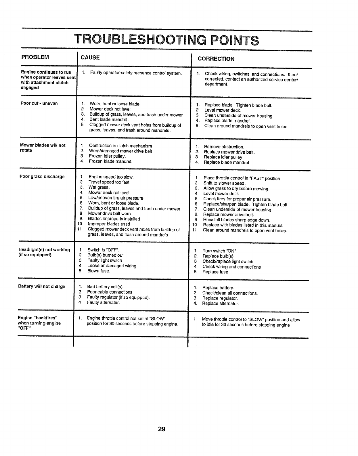
PROBLEM
Engine continues to run
when operator leaves seat
with attachment clutch
engaged
Poorcut*uneven
Mower blades wilt not
rotate
Poor grass d|scharga
Headlight(s) not working
(if so equipped)
Battery will not charge
Engine "backfires"
when turning eng|ne
"OFF"
iii ,,ll ,11JiiLHIII JLIII,, I I
TROUBLESHOOTmNG POmNTS
...................................... , .................... ,, ,, .....
CAUSE
t Faulty operator-safety presence control system.
1. Worn, bent or loose blade
2 Mower deck not levet,
3,, Buildup of grass, leaves, and trash under mower
4 Bent blade mandrel.
5,, Clogged mower deck vent holes from buildup of
grass, leaves, and trash around mandrels.
1. Obstruction in clutchmechanism.
2, Worn/damaged mower drive belt.
3. Frozen idler pulley.
4 Frozen blade mandrel
1, Engine speed too slow,
2. Traveispeed too fast.
3 Wet grass,
4 Mower deck not tave_
5 Low/uneven tire air pressure
6 Worn, bent or loose blade,,
7, Buildup of grass, leaves and trash under mower.
8 Mower drive belt worn
9, Blades improperly installed
t0. _mproper blades used
1I Clogged mower deck vent holes from buitdup of
grass, leaves, and trash a_ound mandrels
1 Swttch fs "OFF",
;2 Bulb(s) burned out.
3 Faulty light switch
4 Loose or damaged wiring
5 BIown fuse.
t, Bad battery ee_l(s)
2. Poor cable connections
3 Faulty regulator (if so equipped).,
4, Fautty alternator..
I, Engine throttle control not set at "SLOW"
position for 30 seconds before stopping engine.
CORRECTION
Check wiring, switches and connections,, If not
corrected, contact an authorized service center/
department,
ii, i JJJJJJii i ,ll JJJ/ i, uJJ,,,, ,,,,
t. Replace blade, Tighten blade bolt.,
2 Level mower deck,
3 Clean underside of mower housing
4. Replace blade mandrel
5 Clean around mandrels to open vent holes
1 Remove obstruction.,
2,, Replace mower ddve belt,,
3 Replace idfer pulley,
4r Replace blade mandrel,
1 Place throttle control In "FAST" position
2 Shift to slower speed,
3. Allow grass to dry before mow_ng.
4 Level mower deck,
5, Check tires for proper air pressure,,
6. Repiace/sharpen blade,, Tighten blade boft
7 Clean underside of mower housing
8 Replace mower drive bell
9, Reinstall blades sharp edge down,
10. Replace with blades I_stedin this manual,
t 1 Clean around mandrels lo open vent holes.,
1. Turn switch"ON"
2 Replace bulb(s),
3 Check/replace light switch,,
4. Check wiring and connections,
5. Replace fuse
., Replace battery,
2, Check]clean aft connections..
3 Replace regulator.
4. Replace alternator,
Move throttle controf to "SLOW" position and allow
to idle for 30 seconds before slopping engine,
29

SERVICE NOTES
30
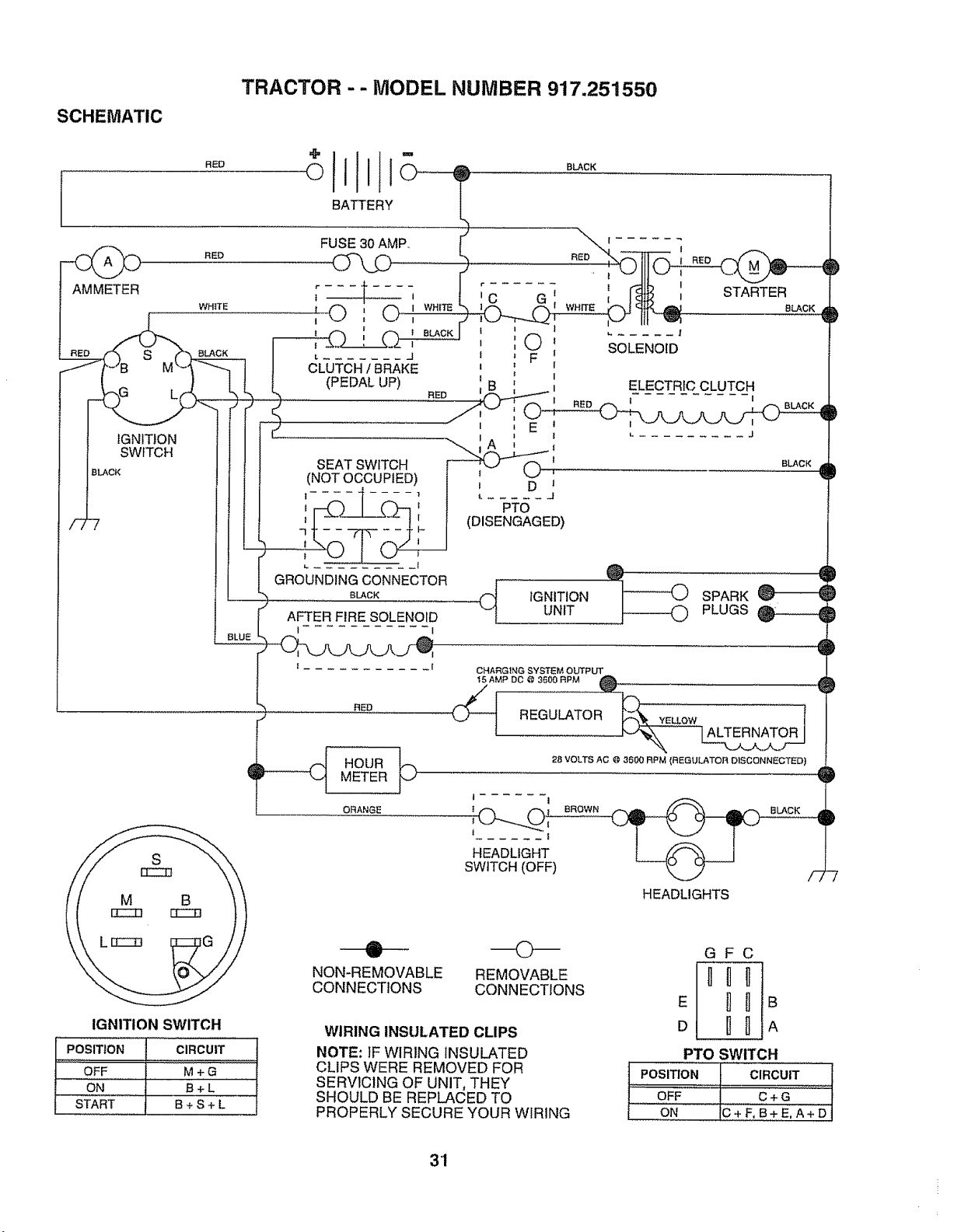
TRACTOR -- MODEL NUMBER 917.251550
SCHEMATIC
RED
BATTERY
BLACK
AMMETER
RED
WHITE
S aLAcK
FUSE 30 AMP_
t , i C
' © ' C> ,w.,_
! l i 1
l l ',O I
L ....... J I J F i
CLUTCH t BRAKE t _ I
(PEDAL UP) i I
I
FlED
IGNITION
SWITCH
BLACK
SEAT SWITCH
(NOT OCCUPIED)
AFTER FIRE SOLENOID
I I
--, RED
__@ HOUR
METER
ORANGE
IGNITION SWITCH
POSITION
OFF
ON
START
@
NON-REMOVABLE
CONNECTIONS
f
SOLENOID
@
IGNITION
UNIT
t l
i
I I
HEADLIGHT
SWITCH (OFF)
CIRCUIT
M+G
B+L
B+S+L
©
REMOVABLE
CONNECTIONS
WIRING INSULATED CLIPS
NOTE: IF WIRING INSULATED
CLIPS WERE REMOVED FOR
GFC
E
A
PTO SWITCH
POSITION CIRCUIT
SERVICING OF UNIT, THEY
SHOULD BE REPLACED TO
PROPERLY SECURE YOUR WIRING
,:,, ,,,,,... ...... .... ;.....
OFF C + G
ON IC+F,B+E,A+D
3'1
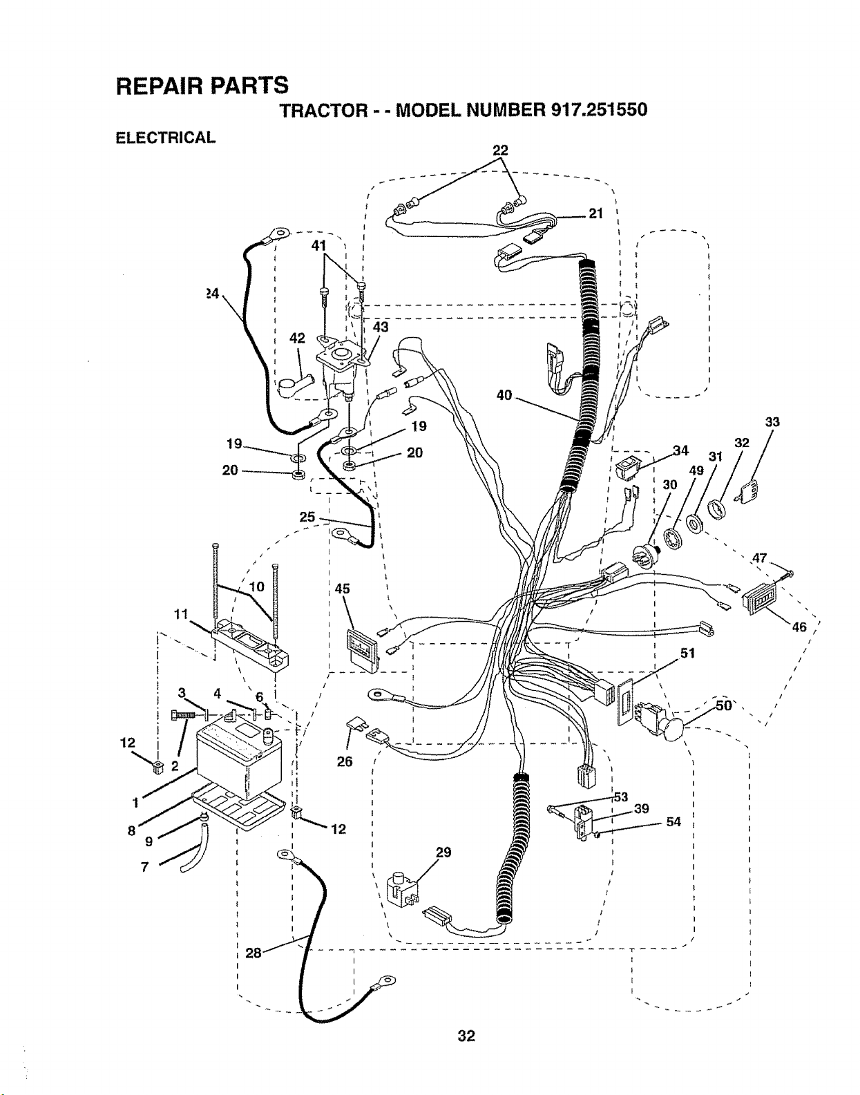
REPAIR PARTS
TRACTOR -- MODEL NUMBER 917,251550
ELECTRICAL
22
11
_'%,,
J '_
J
i
12 i /
2O
\
4
45
19
20
32
51
54
29
32
33
%
46
[
/
/
J
t
/
/
l
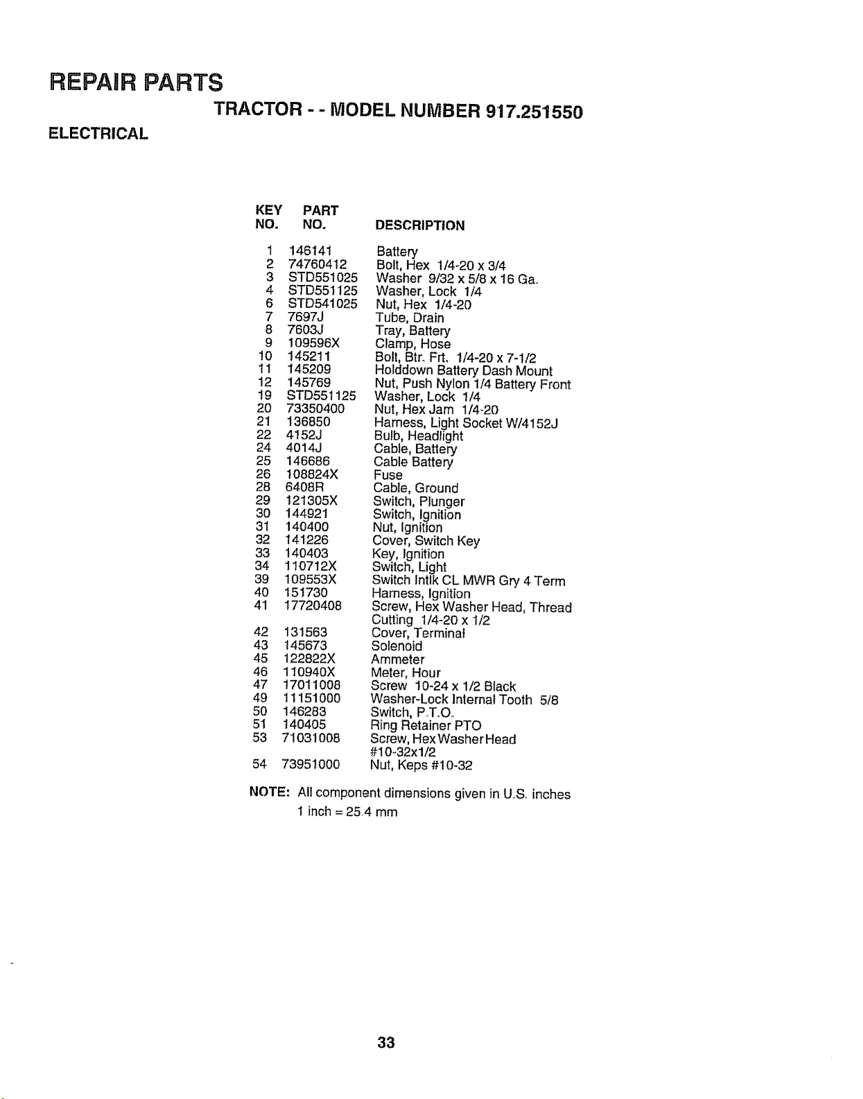
REPAIR PARTS
TRACTOR - - MODEL NUMBER 917.251550
ELECTRICAL
KEY PART
NO. NO. DESCRIPTION
1 146141 Battery
2 74760412 Bolt, Hex 1/4-20 x 3/4
3 STD551025 Washer 9/32 x 5/8 x 16 Ga,.
4 STD551125 Washer, Lock 1/4
6 STD541025 Nut, Hex 1/4-20
7 7697J Tube, Drain
8 7603J Tray, Battery
9 109596X Clamp, Hose
10 145211 Bolt, Btr. Frt, 1/4-20x7-1/2
11 145209 Holddown Battery Dash Mount
12 145769 Nut, Push Nylon 1/4 Battery Front
19 STD551125 Washer, Lock 1/4
20 73350400 Nut, HexJam 1/4_20
21 136850 Harness, Light Socket W/4152J
22 4152J Bulb, Headlight
24 4014J Cable, Batlery
25 146686 Cable Battery
26 108824X Fuse
28 6408R Cable, Ground
29 121305X Switch, Plunger
30 144921 Switch, Ignition
31 140400 Nut, Ignition
32 141226 Cover, Switch Key
33 140403 Key, Ignition
34 110712X Switch, Light
39 I09553X Switch Intlk CL MWR Gry 4 Term
40 15!730 Harness, Ignition
41 17720408 Screw, Hex Washer Head, Thread
Cutting 1/4-20 x 1/2
42 131563 Cover, Terminal
43 t45673 Solenoid
45 122822X Ammeter
46 110940X Meter, Hour
47 17011008 Screw !0-24x 1/2 Black
49 1! 151000 Washer-Lock Internal Tooth 5/8
50 146283 Switch, P..T,.O,.
51 140405 Ring RetainerPTO
53 71031008 Screw, HexWasher Head
#10-32xl/2
54 73951000 Nut, Keps #10-32
NOTE: All component dimensions given in US. inches
! inch = 25,4 mm
33
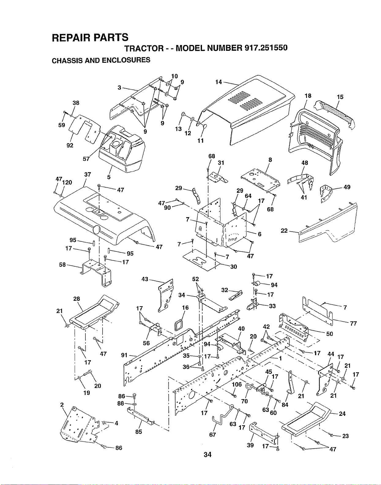
REPAIR PARTS
TRACTOR - - MODEL NUMBER 917.251550
CHASSIS AND ENCLOSURES
59
92
38
11
57
91
/
42
56
85
1
i
17
67
7O
86
39
34
18 15
/
48
41
49
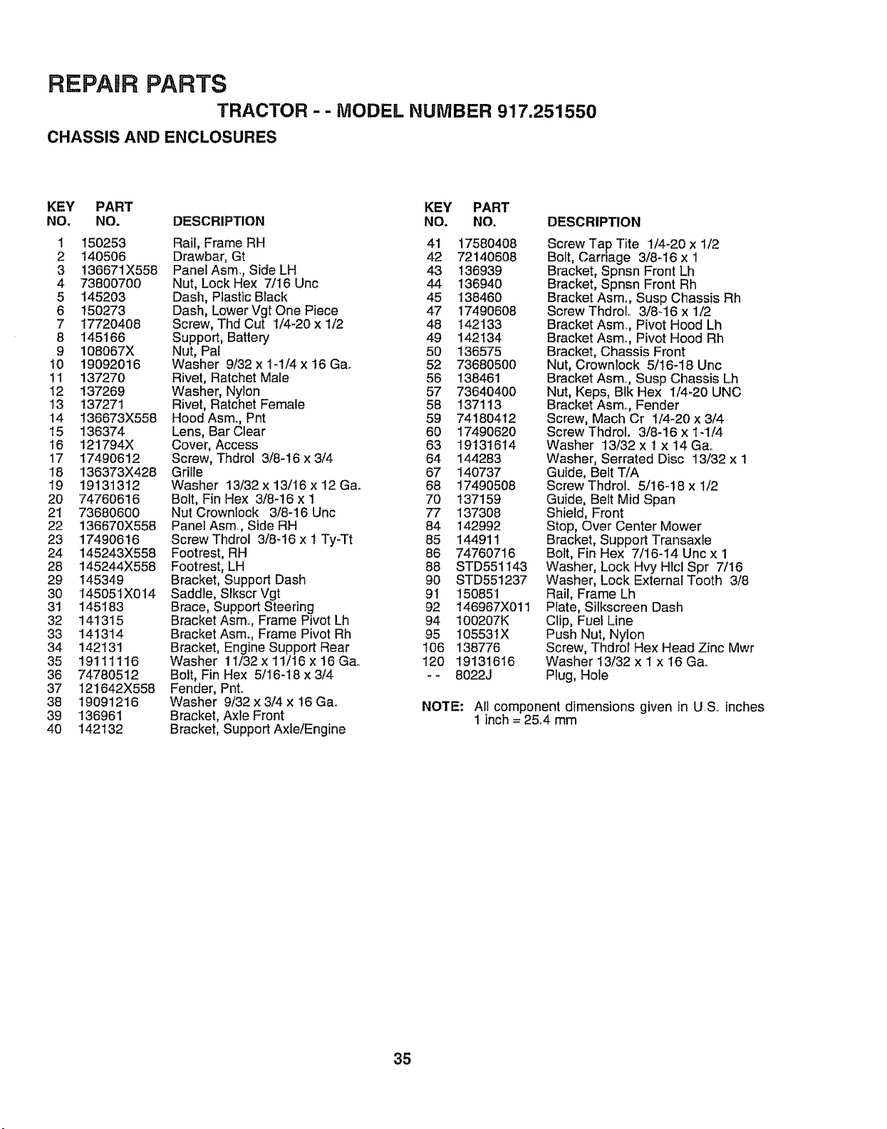
REPARR PARTS
TRACTOR -- MODEL NUMBER 917.251550
CHASSIS AND ENCLOSURES
KEY PART KEY PART
NO. NO. DESCRIPTION NO. NO. DESCRIPTION
1 150253 Rail, Frame RH 41 17580408
2 140506 Drawbar, Gt 42 72140608
3 136671X558 PanelAsm., Side LH 43 136939
4 73800700 Nut, Lock Hex 7/16 Unc 44 136940
5 145203 Dash, Plastic Btack 45 138460
6 150273 Dash, Lower Vgt One Piece 47 17490608
7 17720408 Screw, Thd Cut 1/4-20 x 1/2 48 142133
8 145166 Support, Battery 49 142134
9 108067X Nut, Pat 50 136575
10 19092016 Washer 9/32 x 1-1/4 x 16 Ga. 52 73680500
11 137270 Rivet, Ratchet Male 56 !38461
12 137269 Washer, Nylon 57 73640400
13 137271 Rivet, Ratchet Female 58 t371 t3
14 136673X558 Hood Asm., Pnt 59 74180412
15 136374 Lens, Bar Clear 60 17490620
16 121794X Cover, Access 63 19131614
17 17490612 Screw, Thdrol 3/8-16 x 3/4 64 144283
18 136373X428 Grille 67 140737
19 19131312 Washer 13/32x 13/+16x 12 Ga+ 68 17490508
20 74760616 Bolt, Fin Hex 3/8-t6 x 1 70 137159
21 73680600 Nut Crownlock 3/8-16 Unc 77 137308
22 136670X558 Panel Asm, Side RH 84 142992
23 17490616 Screw Thdrol 3/8-16 x ! Ty-Tt 85 144911
24 145243X558 Footrest, RH 86 74760716
28 145244X558 Footrest, LH 88 STD551 t43
29 145349 Bracket, Support Dash 90 STD551237
30 145051X014 Saddle, SIkscr Vgt 91 150851
31 145183 Brace, Support Steering 92 146967X011
32 141315 BracketAsm. Frame Pivot Lh 94 100207K
33 141314 Bracket Asm., Frame Pivot Rh 95 I05531X
34 142131 Bracket, Engine Support Rear 106 138776
35 19111116 Washer 11i32xlli16x16Ga,+ I20 19131616
36 74780512 Bolt, Fin Hex 5/16-18 x3/4 -- 8022J
37 121642X558 Fender, Pnt+
38 19091216 Washer 9i32x3/4x 16Ga.
39 136961 Bracket, Axle Front
40 142132 Bracket, Support Axle!Engine
Screw Tap Tite 1/4-20 x 1/2
Bolt, Carriage 3/8-16 x 1
Bracket, Spnsn Front Lh
Bracket, Spnsn Front Rh
Bracket Asm+, Susp Chassis Rh
ScrewThdroL 3/8+16 x 1/2
Bracket Asm+, Pivot Hood Lh
Bracket Asm. Pivot Hood Rh
Bracket, Chassis Front
Nut, Crownlock 5/16-18 Unc
Bracket Asm+, Susp Chassis Lh
Nut, Keps, BIk Hex 1/4+20 UNC
Bracket Asmo, Fender
Screw, Mach Cr 1/4-20 x 3/4
Screw Thdrol+ 3/8-16 x 1+1/4
Washer 13/32 x 1 x 14 Gao
Washer, Serrated Disc 13/32 x 1
Guide, Belt T/A
Screw ThdroL 5/16-18 x 1/2
Guide, Belt Mid Span
Shield, Front
Stop, Over Center Mower
Bracket, Support Transaxie
Bolt, Fin Hex 7/16-14 Unc x 1
Washer, Lock Hvy Hlcl Spr 7/16
Washer, Lock External Tooth 3/8
Rail, Frame Lh
PIate, Silkscreen Dash
Clip, Fuel Line
Push Nut, Nylon
Screw, Thdrol Hex Head Zinc Mwr
Washer 13/32 x 1 x 16 Ga,.
Plug, Hole
NOTE: All component dimensions given in U..S. inches
1 inch = 25,4 mm
35
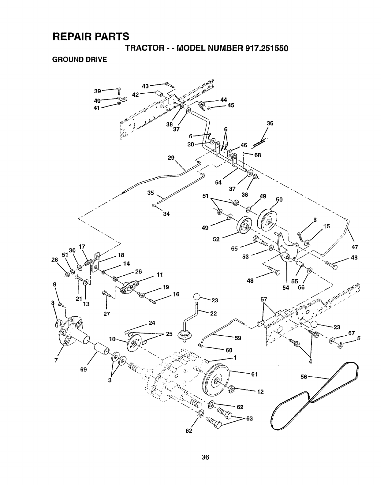
"" MODEL NUMBER 977"251550
4
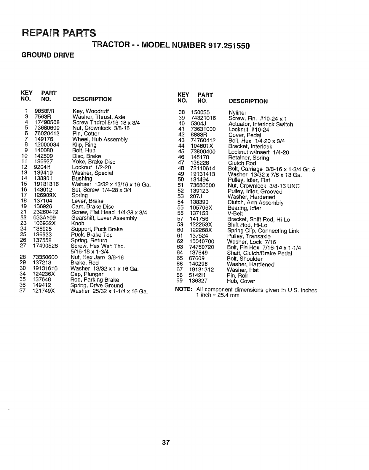
REPAIR PARTS
TRACTOR -- MODEL NUMBER 917.251550
GROUND DRIVE
KEY PART KEY PART
NO. NO. DESCRIPTION NO. NO. DESCRIPTION
1 9858M1 Key, Woodruff 38 150035
3 7563R Washer, Thrust, Axle 39 74321016
4 17490508 Screw Thdrol 5/16-18 x 3/4 40 5304J
5 73680600 Nut, Crownlock 3/8-16 41 73631000
6 76020412 Pin, Cotter 42 8883R
7 149176 WheeE,Hub Assembly 43 74760412
8 12000034 Klip, Ring 44 104601X
9 140080 Bolt, Hub 45 73800400
10 142509 Disc, Brake 46 145170
11 136927 Yoke, Brake Disc 47 138228
12 9204H Locknut 1/2-20 48 72110614
13 139419 Washer, Special 49 19131413
14 138901 Bushing 50 131494
15 19131316 Wahser 13/32 x 13/'16x 16 Ga.. 51 73680600
16 143012 Set, Screw 1/4-28 x 3/4 52 139123
17 126909X Spring 53 207J
18 137104 Lever, Brake 54 t38390
19 136926 Cam, Brake Disc 55 105706X
21 23260412 Screw, Flat Head t/4-28 x 3/4 56 137153
22 633At09 Gearshift, Lever Assembly 57 141756
23 106932X Knob 59 122253X
24 136925 Support, Puck Brake 60 122268X
25 136923 Puck, Brake Top 61 137524
26 137552 Spring, Return 62 10040700
27 17490528 Screw, Hex Wsh Thd. 63 74760720
5/16-18 x 1-3/4 64 137649
28 73350600 Nut, Hex ,Jam 3/8-16 65 67609
29 137213 Brake, Rod 66 140296
30 19131616 Washer 13/32 x 1 x 16 Ga. 67 19131312
34 124236X Cap, Plunger 68 5142H
35 137648 Rod, Parking Brake 69 136327
36 149412 Spring, Drive Ground
37 121749X Washer 25/32 x 1-1/4 x 16 Ga..
Nyliner
Screw, Fin. #10-24 x 1
Actuator, Interlock Switch
Locknut #10-24
Cover, Pedal
Bolt, Hex t/4-20 x 3/4
Bracket, Interlock
Locknut w/Insert 1/4-20
Retainer, Spring
Clutch Rod
Bolt, Carriage 3/8-16 x 1-3/4 Gr. 5
Washer 13/32 x 7/8 x 13 Ga..
Puliey, Idler, Flat
Nut, Crownlock 3/8-16 UNC
Pulley, Idler, Grooved
Washer, Hardened
Clutch, Arm Assembly
Bearing, Idler
V-Belt
Bracket, Shift Rod, Hi-Lo
Shift Rod, Hi-Lo
Spring Clip, Connecting Link
Pulley, Transaxie
Washer, Lock 7/16
Bolt, Fin Hex 7/16-14 x 1-1/4
Shaft, Clutch/Brake Pedal
Bolt, Shoulder
Washer, Hardened
Washer, Flat
Pin, Roll
Hub, Cover
NOTE: Air component dimensions given in US. inches
1 inch = 25.4 mm
37
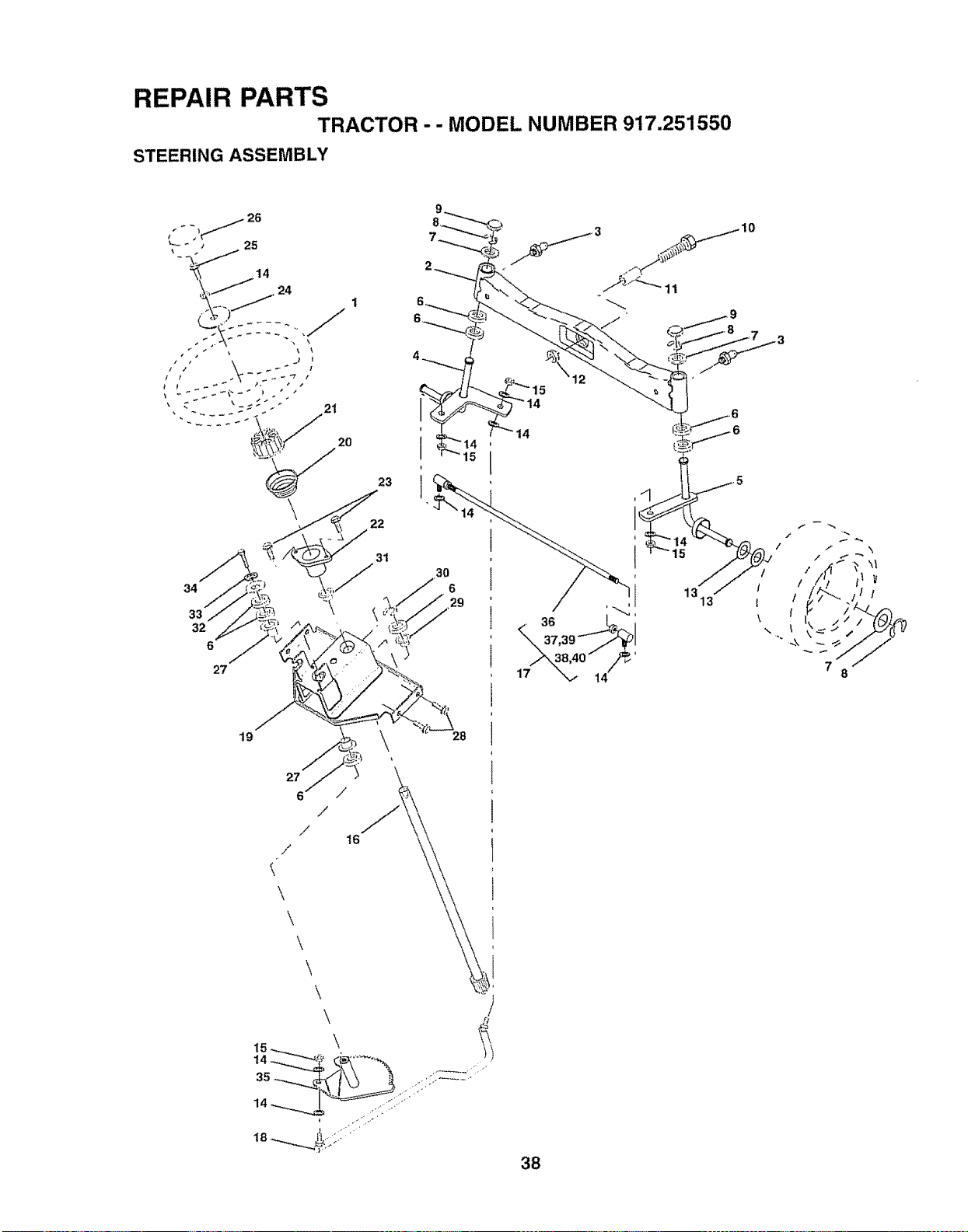
I_EPAIRPAt_TS
TRACTOR
STEERING ASSEMBLy
27
/
/
28
/
/
/
/
\ I
/
/
/
" " MODEL NUMBER 917.251550
/
/
38

REPAIR PARTS
TRACTOR -- MODEL NUMBER 917,251550
STEERING ASSEMBLY
KEY PART
NO_ NO. DESCRIPTION
1 121472X
2 137094
3 6855M
4 136960
5 136959
6 6266H
7 121748X
8 12000029
9 121232X
10 74781044
11 136518
12 73901000
13 121749X
14 10040600
15 73610600
16 145103
17 137347
18 137155
19 146611
20 145182
21 1007!1L
22 1554J
23 17431008
24 19133808
25 74780616
26 126805X
27 3366R
28 17490612
29 104239X
30 12000034
31 138136
32 19111610
33 1O040500
34 74760512
35 138059
36 137156
37 733606O0
38 109850X
39 73700600
40 109851X
Wheel, Steering
Axle Asm, Front
Fitting, Grease
Spindle Asm, LH
Spindle Asm., RH
Bearing, Race Thrust Harden
Washer 25/32 x 1-5/8 x 16 Ga.
Ring, Klip #75304-75
Cap, Spindle
Bolt, Fin Hex 5/8-! 1 x 2-3/4
Spacer, BrgoAxle Front
Nut, Lock Flange 5/8-!1 Unc
Washer 25/32 x 1-1/4 x 16 Ga.
i_lCasher,Lock Hvy Hlcl Spr 3/8
ut, Fin Hex 3/8-24 Unf
Shaft Asmo, Steering
Rod Asm., Tie Ball J Ball Vgt (lnc,.
Key No. 36-40)
Draglink, Ball Joint Solid Vgt
Support Asmo, Steering Vgt
Column, Steering
Adapter, Wheel Steering
Bushing, Strg. Blk
Screw, Stftp #10-16 x 1/2 Ty-b
Washer 13/32 x 2-3/8 x 8 Ga,.
Bolt, Fin Hex 3/8-16 x I Gr. 5
Cap, Wheel Steering
Bearing, Col. Strg.
Screw, Thrdrol 3/8-16 x 3/4
Bearing, Flange
Ring, Kiip Truarc #5304-75
Bushing, Nyliner Snap
Washer 11/32 x i x 10 Ga.
Washer, Lock Hvy Hlcl Spr 5/t6
Bolt, Hex Hd 5/16-18 x 3/4
Gear, Sector Steering
Tie Rod
Jam Nut RH Thread
Joint Asm. Ball RH Thread
Jam Nut LH Thread
Joint Asm. Bal! LH Thread
NOTE: All component dimensions given in U.,S.inches
1 inch = 25.4 mm
39
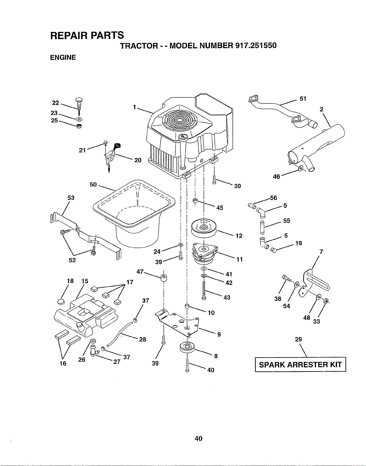
REPAIRPART8
ENQINE TRACTOR
""MODEL NUMBER 917.251550
S
16
23
52
t
26
"37
28
3g
//
9
41
42
39
12
11
5
j 55
38
54
48
33
29
51
7
2
40

REPAIR PARTS
TRACTOR -- MODEL NUMBER 917.251550
ENGINE
KEY PART
NO, NO. DESCRIPTION
1 140847
2 144636
5 13200300
7 143599
8 t21361X
9 145109
t0 !05432X
11 140923
12 143996
15 151346
16 109227X
17 106082X
18 151296
19 13290300
20 132755
21 17720410
22 132779
23 19132616
24 11050600
25 7361O6OO
26 3645J
27 139277
28 7834R
29 132920
33 73800600
37 123487X
38 74780624
39 1749O636
40 17490664
41 126197X
42 10040700
43 150280
45 128861
46 19131616
47 142040
48 19132007
50 143020
51 140787
52 1758O4O8
53 143528
54 19131414
55 13090336
56 13090308
Engine Kohrer 22 CV22 PS-67515
Muffler Asm
Elbow STD 90 Degree 3/8 - 18 NPT
Muffler Asm Guard
Pulley V-Idler
Stop Keeper Asm VGT
Bushing
Clutch Electric
Pulley Engine VGT Elect Clutch
Tank Fuel Rear 3.50 Yt/Gt 96
Pad Spacer
Pad Spacer
Cap Asm Fuel W/Gauge Vented
Plug Oil Drain (Order From Engine
Manufacturer)
Control Throttle
Screw Hex Thd Cut 1/4 - 20 X 5/8
Control Choke
Washer t3/32 X 1 _5/8 X 16 Ga
Washer Ext Tooth 3/8
Nut Fin Hex 3/8 - 24 UNF
Bushing
Stem Tank Fuel
Fuel Line
Spark Arrester Kit
Nut Lock Hex w/Inso 3/8 - 16
Clamp Hose
Bolt Fin Hex 3/8 - 16 x t-1/2
Screw TT 3/8-16 x 2-1/4 UNC
Screw TT 3/8-16 x 4 UNC
Washer 1-1/20D X 15/32 ID X °250
Washer Lock 7/16
Bolt Hex 7/16 - 20 X 4 - 1/4 Ga 5
Nut Flange 1/4-20 Starter Nut
Washer 13/32 x 1 x 16 Ga,,
Spacer Engine
Washer t3/32 x 1-1/4 x 7 Gao
Duct Air
Pipe Crossover
Screw Tap 1/4 - 20 x 1/2
Bracket Duct Air Rear Sup
Washer Flat 13/32 x 7/8 x 14 Ga,
Nipple Pipe 3/SNPT X 4-1/2
Nipple Pipe 3/8 x 1
NOTE: Altcomponent dimensions given in U.S. inches
linch = 25,4 mm
41
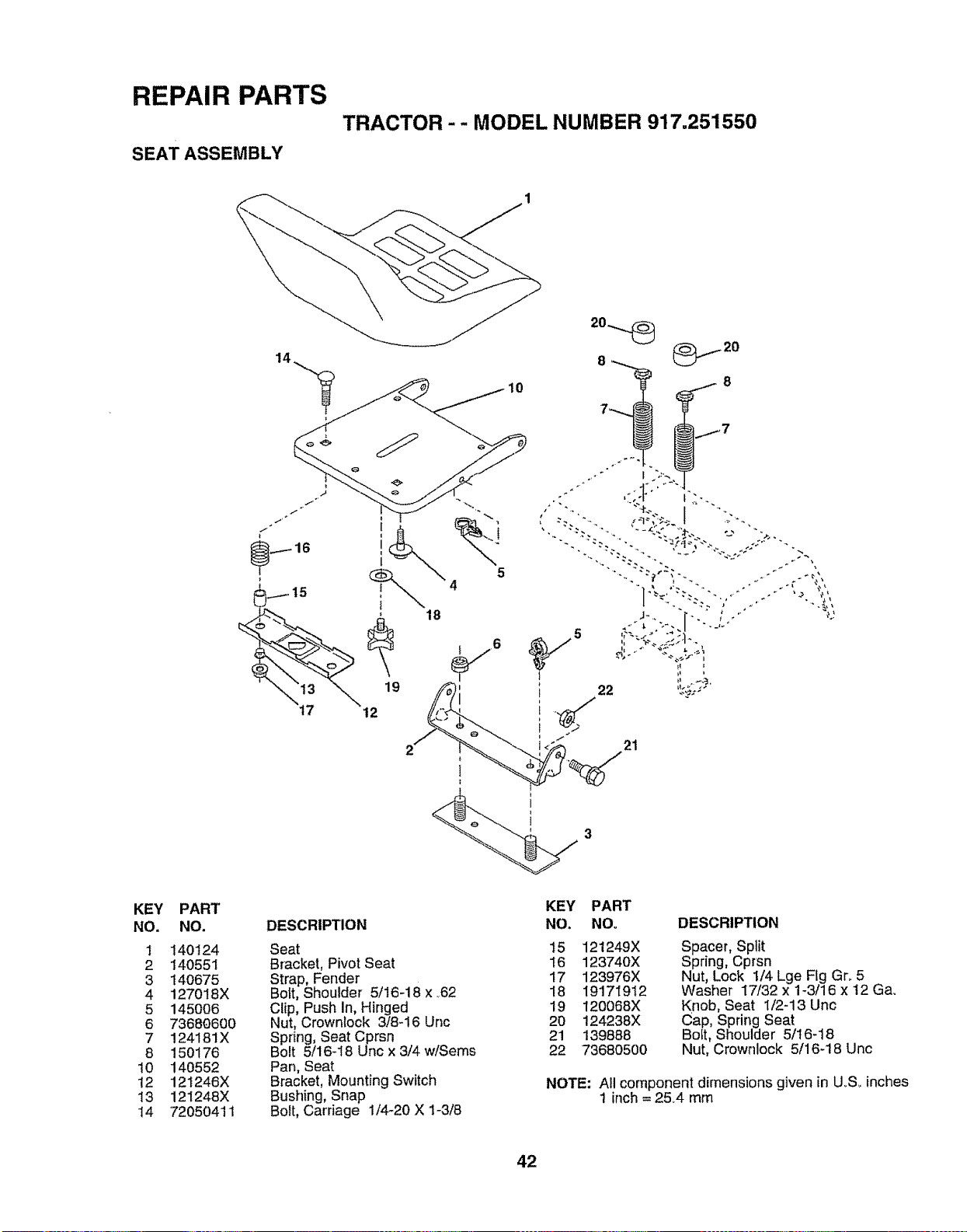
REPAIR PARTS
SEAT ASSEMBLY
TRACTOR-- MODEL NUMBER 917.251550
KEY PART
NO. NO.
1 140124
2 140551
3 140675
4 127018X
5 145OO6
6 73680600
7 !24181X
8 150176
t0 140552
12 121246X
13 121248X
14 72050411
18
19
12
!i !
2' 21
3
DESCRIPTION
Seat
Bracket, Pivot Seat
Strap, Fender
Bolt, Shoulder 5/16-18 x ,62
Clip, Push In, Hinged
Nut, Crownlock 3/8-16 Unc
Spring, Seat Cprsn
Bolt 5/16-18 Unc x 3/4 w/Seres
Pan, Seat
Bracket, Mounting Switch
Bushing, Snap
Bolt, Carriage 1/4_20 X 1-3/8
KEY PART
NO. NOo
15 121249X
16 123740X
17 123976X
18 19171912
19 120068X
2O 124238X
21 139888
22 73680500
DESCRIPTION
Spacer, Split
Spring, Cprsn
Nut, Lock 1/4 Lge Fig Gro 5
Washer 17/32 x 1-3/16 x 12 Ga,
Knob, Seat 1/2-13 Unc
Cap, Spring Seat
Boft, Shoulder 5/16-18
Nut, Crownlock 5/16-18 Unc
NOTE: All component dimensions given in U_S_inches
1 inch = 2&4 mm
42
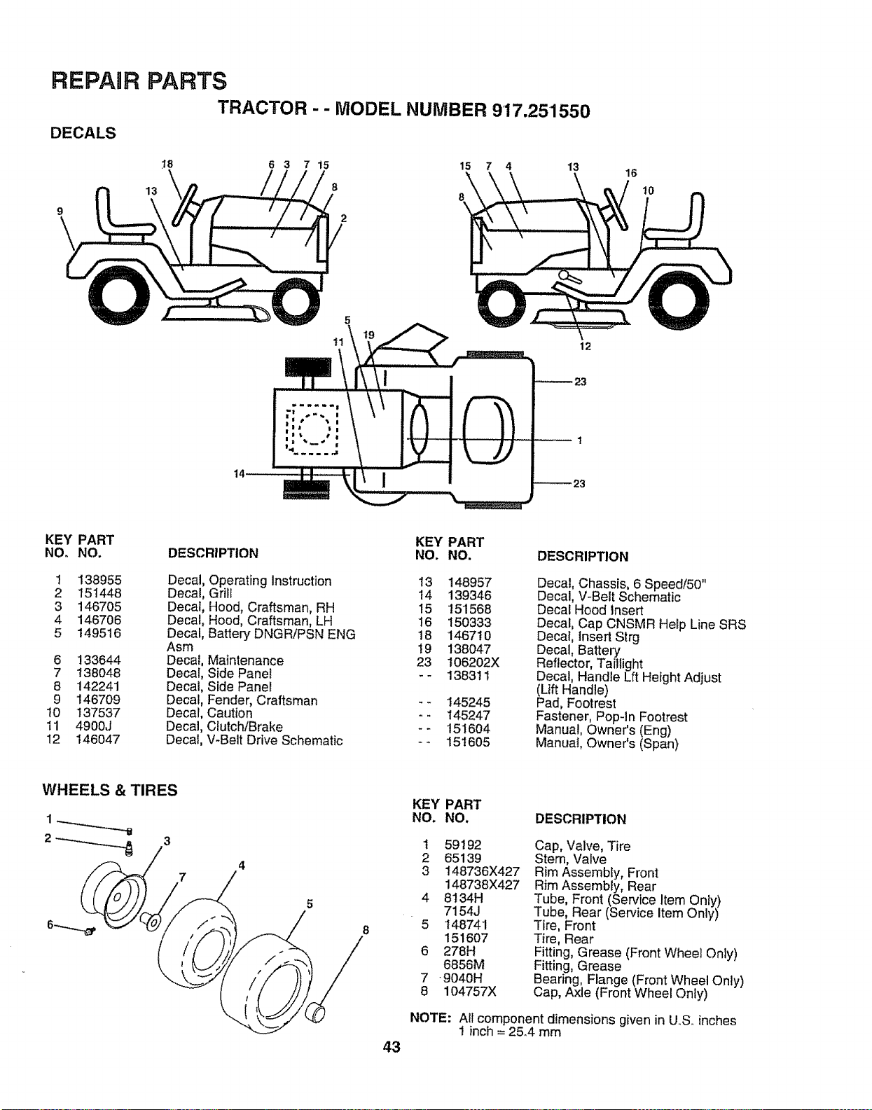
REPAIR
DECALS
PARTS
TRACTOR - - MODEL NUMBER 9'17.25'1550
13
:I8 6 3 7 15 15 7 4 13
8
8
\
16
10
5
11
12
KEY PART
NO° NO.
1 138955
2 151448
3 146705
4 146706
5 149516
6 133644
7 138048
8 142241
9 146709
t0 137537
11 4900J
12 146047
KEY PART
DESCRIPTION NO. NO,
Decal, Operating Instruction 13 148957
Decal, Grill 14 139346
Decal, Hood, Craftsman, RH 15 151568
Decal, Hood, Craftsman, LH I6 150333
Decal, Battery DNGRiPSN ENG 18 146710
Asm 19 138047
Decal, Maintenance 23 I06202X
Decal, Side Panel -- 138311
Decal, Side Panel
Decal, Fender, Craftsman -- 145245
Decal, Caution - - 145247
Decal, Clutch/Brake - - 151604
Decal, V-Belt Drive Schematic -- 151605
DESCRIPTION
Decal, Chassis, 6 Speed/50"
Decal, V-Belt Schematic
Decal Hood Insert
Decal, Cap CNSMR Help Line SRS
Decal, Insert Strg
Decal, Battery
Reflector, Taillight
Decal, Handle Lft Height Adjust
(Lift Handle)
Pad, Footrest
Fastener, Pop-In Footrest
Manual, Owner's (Eng)
Manuat, Owner's (Span)
8
43
KEY PART
NO. NO.
DESCRIPTION
t 59192
2 65139
3 148736X427
148738X427
4 8134H
7154J
5 148741
151607
6 278H
6856M
7 9040H
8 104757X
Cap, Valve, Tire
Stem, Valve
Rim Assembly, Front
Rim Assembly, Rear
Tube, Front (Service Item Only)
Tube, Rear (Service Item Only)
Tire, Front
Tire, Rear
Fitting, Grease (Front Wheel Only)
Fitting, Grease
Bearing, Flange (Front Wheel Only)
Cap, Axle (Front Wheel Only)
NOTE: AII component dimensions given in U..S,.inches
i inch= 2&4 mm
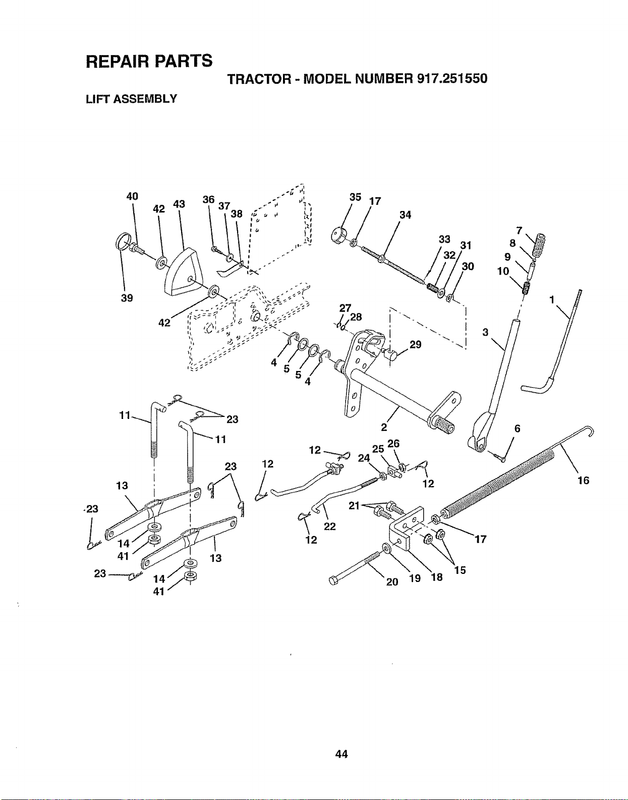
REPAIR PARTS
LIFT ASSEMBLY
TRACTOR - MODEL NUMBER 917.251550
40
42 43
39
42
!
13
41 13
4
12
35 17
34
29
22
12
15
20 19 18
44
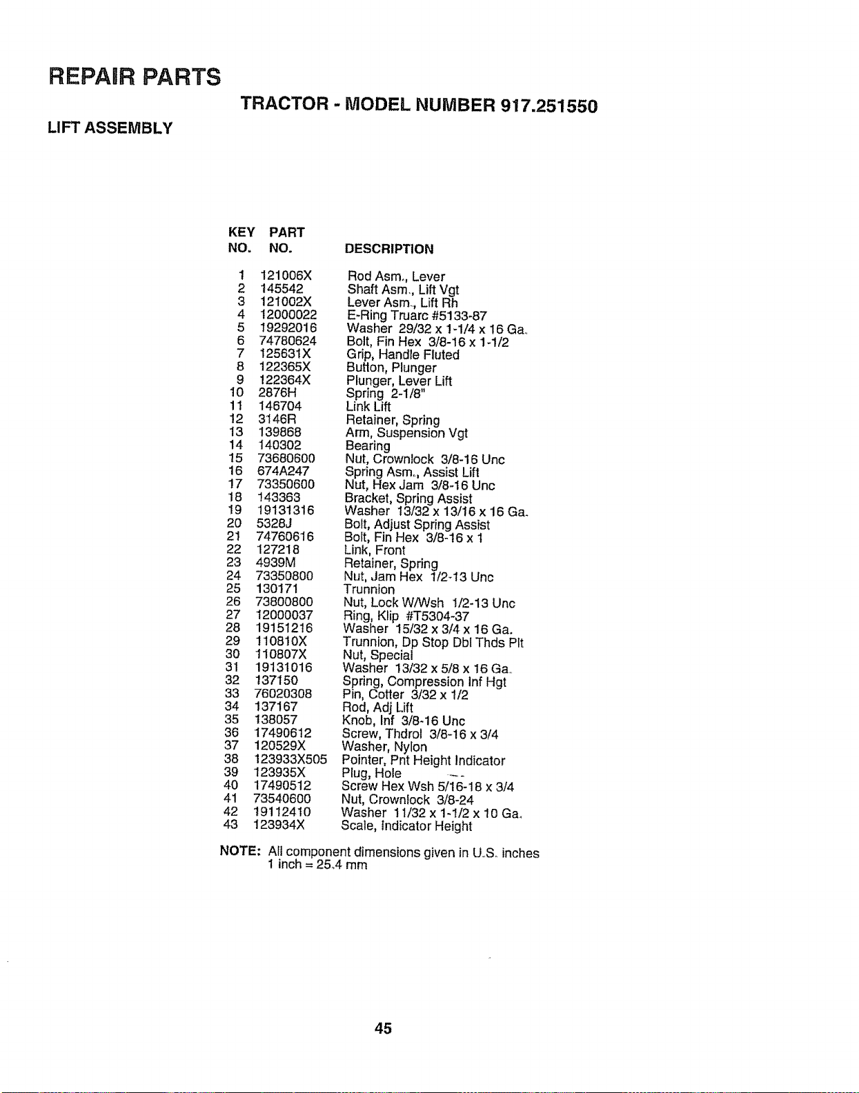
REPAIR PARTS
LIFT ASSEMBLY
TRACTOR - MODEL NUMBER 917.251550
KEY PART
NO. NO. DESCRIPTION
1 121006X
2 145542
3 12i002X
4 12000022
5 19292O16
6 74780624
7 128631X
8 122365X
9 122364X
10 2876H
11 146704
12 3146R
13 139868
14 14O302
15 73680600
16 674A247
!7 73350600
18 143363
19 19131316
20 5328J
21 74760616
22 127218
23 4939M
24 73350800
25 130171
26 73800800
27 12000037
28 19151216
29 110810X
30 110807X
31 19131016
32 137150
33 76020308
34 137167
35 138057
36 17490612
37 120529X
38 123933X505
39 123935X
40 17490512
41 73540600
42 19112410
43 123934X
Rod Asmo, Lever
Shaft Asm, LiftVgt
Lever Asm, Lift Rh
E-Ring Truarc #5133-87
Washer 29/32 x lq/4 x 16 Ga.
Bolt, Fin Hex 3/8-i6 x 1-1/2
Grip, Handle Fluted
Button, Plunger
Plunger, Lever Lift
Spring 2-1/8"
Link Lift
Retainer, Spring
Arm, Suspension Vgt
Bearing
Nut, Crownlock 3/8-16 Unc
Spring Asm.., Assist Lift
Nut, Hex Jam 3/8-16 Unc
Bracket, Spring Assist
Washer 13132x 13/16 x 16 Ga.
Bolt, Adjust Spring Assist
Bolt, Fin Hex 3/8-16 x 1
Link, Front
Retainer, Spring
Nut, Jam Hex 1/2-13 Unc
Trunnion
Nut, Lock WiWsh !/2-13 Unc
Ring, Klip #T5304-37
Washer 15/32 x 3/4 x 16 Ga.
Trunnion, Dp Stop Dbl Thds Pit
Nut, Special
Washer 13/32 x 5/8 x !6 Ga..
Spring, Compression inf Hgt
Pin, Cotter 3/32 x t/2
Rod, Adj Lift
Knob, Inf 3/8-16 Unc
Screw, Thdrol 3/8-16 x 3/4
Washer, Nylon
Pointer, Pnt Height Indicator
Plug, Hole
Screw Hex Wsh 5)16--18x 3/4
Nut, Crownlock 3/8-24
Washer 11/32 x 1-1/2 x 10 Ga_
Scale, Indicator Height
NOTE: Afl component dimensions given in U..S.inches
1 inch = 25A mm
45
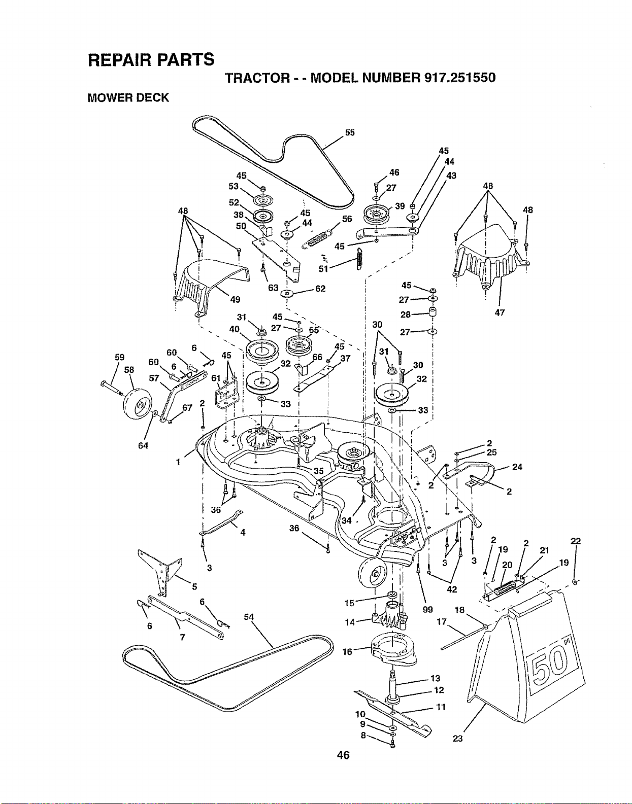
REPAIR PARTS
MOWER DECK
TRACTOR -- MODEL NUMBER 917.251550
60
59
60
58 _
57
64
1
48
55
36
6
54
99
45
42
18
4B
48
47
2
219 2 21 22
11
46
23
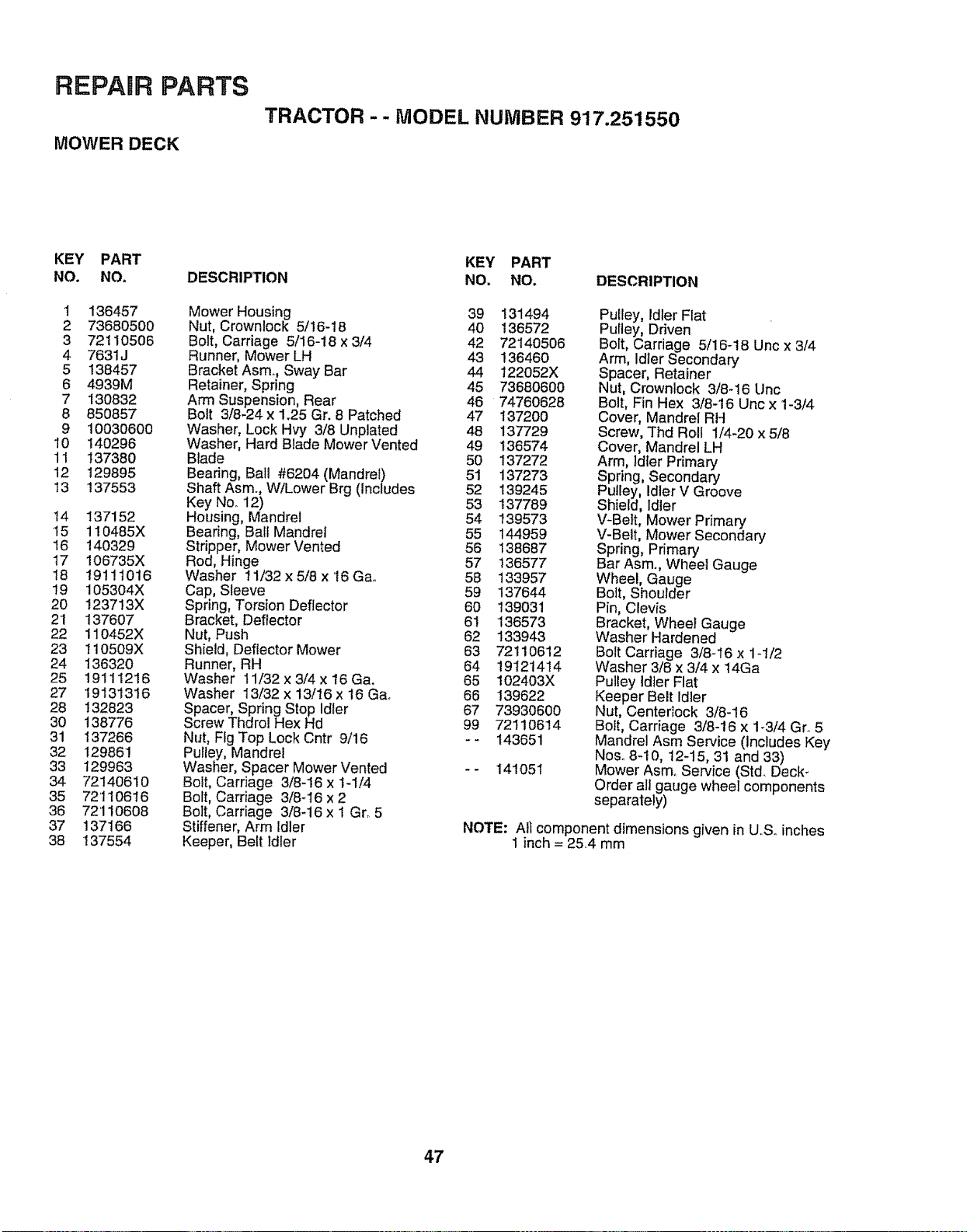
REPARR PARTS
MOWER DECK
TRACTOR -- MODEL NUMBER 917.251550
KEY PART
NO. NO.
1 136457
2 73680500
3 72110506
4 7631J
5 138457
6 4939M
7 130832
8 850857
9 10030600
10 140296
11 137380
12 129895
!3 137553
I4 137152
"15 110485X
16 140329
17 106735X
18 19111016
19 105304X
20 123713X
21 137607
22 110452X
23 110509X
24 136320
25 19111216
27 19131316
28 132823
30 138776
31 137266
32 129861
33 129963
34 72140610
35 72110616
36 72'110608
37 137166
38 137554
DESCRIPTION
Mower Housing
Nut, Crownlock 5/16-18
Bolt, Carriage 5/16-18 x 3/4
Runner, Mower LH
Bracket Asm. Sway Bar
Retainer, Spring
Arm Suspension, Rear
Bolt 3/8-24 x 1.25 Gr. 8 Patched
Washer, Lock Hw/ 3/8 Unptated
Washer, Hard Blade Mower Vented
Blade
Beadng, Ball #6204 (Mandrel)
Shaft Asm., W/Lower Brg (Includes
Key No..12)
Housing, Mandrel
Bearing, Ball Mandrel
Stripper, Mower Vented
Rod, Hinge
Washer 11/32 x 5/8 x 16 Ga°
Cap, Sleeve
Spring, Torsion Deflector
Bracket, Deflector
Nut, Push
Shield, Deflector Mower
Runner, RH
Washer 11/32 x 3/4 x 16 Ga.
Washer 13/32 x 13/16 x 16 G&
Spacer, Spring Stop Idler
Screw Thdrol Hex Hd
Nut, Fig Top Lock Cntr 9/16
Pulley, Mandrel
Washer, Spacer Mower Vented
Bolt, Carriage 3/8-16 x 1-1/4
Bolt, Carriage 3/8-'I6 x 2
Bolt, Carriage 3/8-16 x 1 Gr, 5
Stiffener, Arm Idler
Keeper, Belt Idler
KEY PART
NO, NO, DESCRIPTION
39 131494
40 136572
42 72140506
43 136460
44 122052X
45 73680600
46 74760628
47 137200
48 137729
49 136574
50 137272
51 137273
52 139245
53 137789
54 139573
55 144959
56 138687
57 136577
58 133957
59 137644
60 139031
61 136573
62 133943
63 72110612
64 19121414
65 102403X
66 139622
67 73930600
99 72110614
-- 143651
141051
Pulley, Idler Flat
Pulley, Driven
Bolt, Carriage 5/16-18 Unc x 3/4
Arm, Idler Secondary
Spacer, Retainer
Nut, Crownlock 3/8-16 Unc
Bolt, Fin Hex 3/8-16 Unc x 1-3/4
Cover, Mandrel RH
Screw, Thd Roll 1/4-20 x 5/8
Cover, Mandrel LH
Arm, Idler Primary
Spring, Secondary
Pulley, Idler V Groove
Shield, Idler
V-Belt, Mower Primary
V-Belt, Mower Secondary
Spring, Primary
Bar Asm., Wheel Gauge
Wheel, Gauge
Bolt, Shoulder
Pin, Clevis
Bracket, Wheel Gauge
Washer Hardened
Belt Carriage 3/8-16 x 1-1/2
Washer 3/8 x 3/4 x 14Ga
Pulley Idler Flat
Keeper Belt Idler
Nut, Centerlock 3/8-16
Bolt, Carriage 3/8-16 x 1-3/4 Gro 5
Mandrel Asm Service (Includes Key
Noso8-10, 12-15, 31 and 33)
Mower Asmo Service (Std. Deck_
Order all gauge wheel components
separately)
NOTE: Ali component dimensions given in U,.S.inches
1 inch = 25,4 mm
47
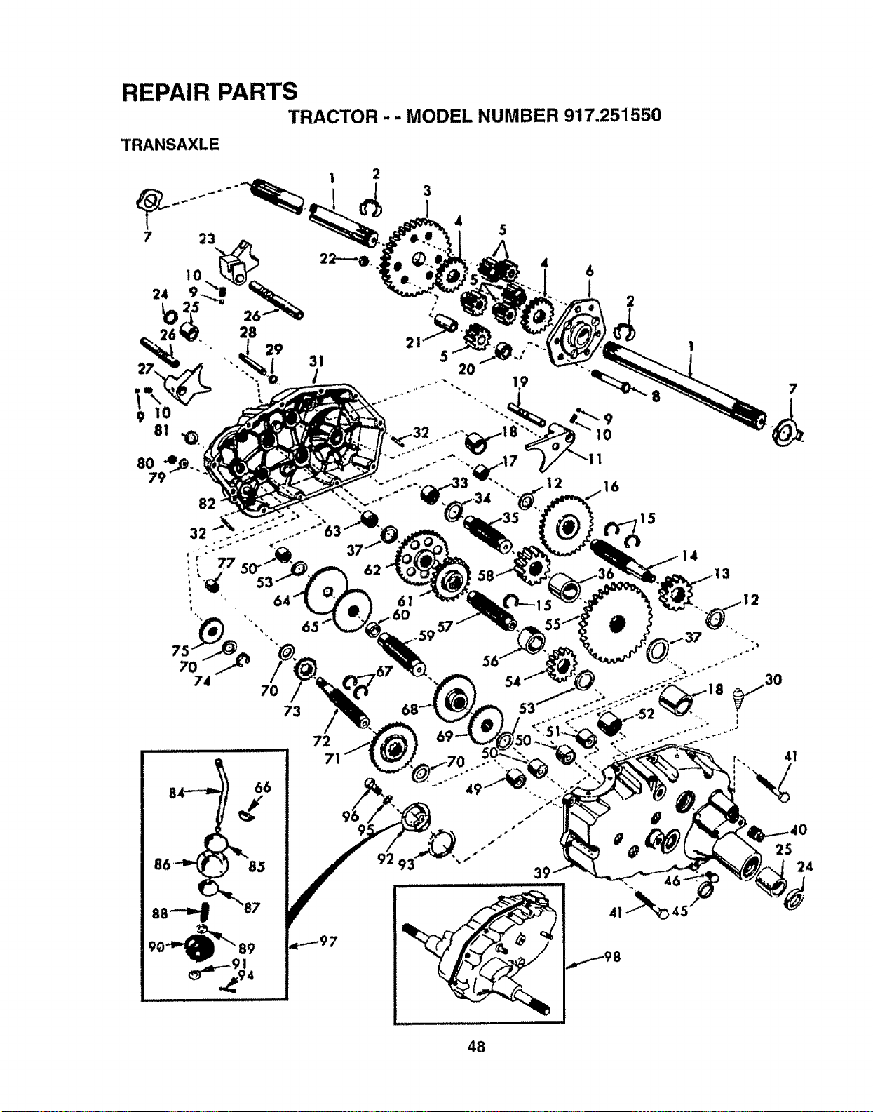
REPAIR PARTS
TRACTOR - - MODEL NUMBER 917.251550
TRANSAXLE
4
5
4
2O
19
6
2
9
10
16
7
I
74
7O
73
72
71
.59 57
92 93
14
3
53
r. 4!
25
41_ 45
24
48
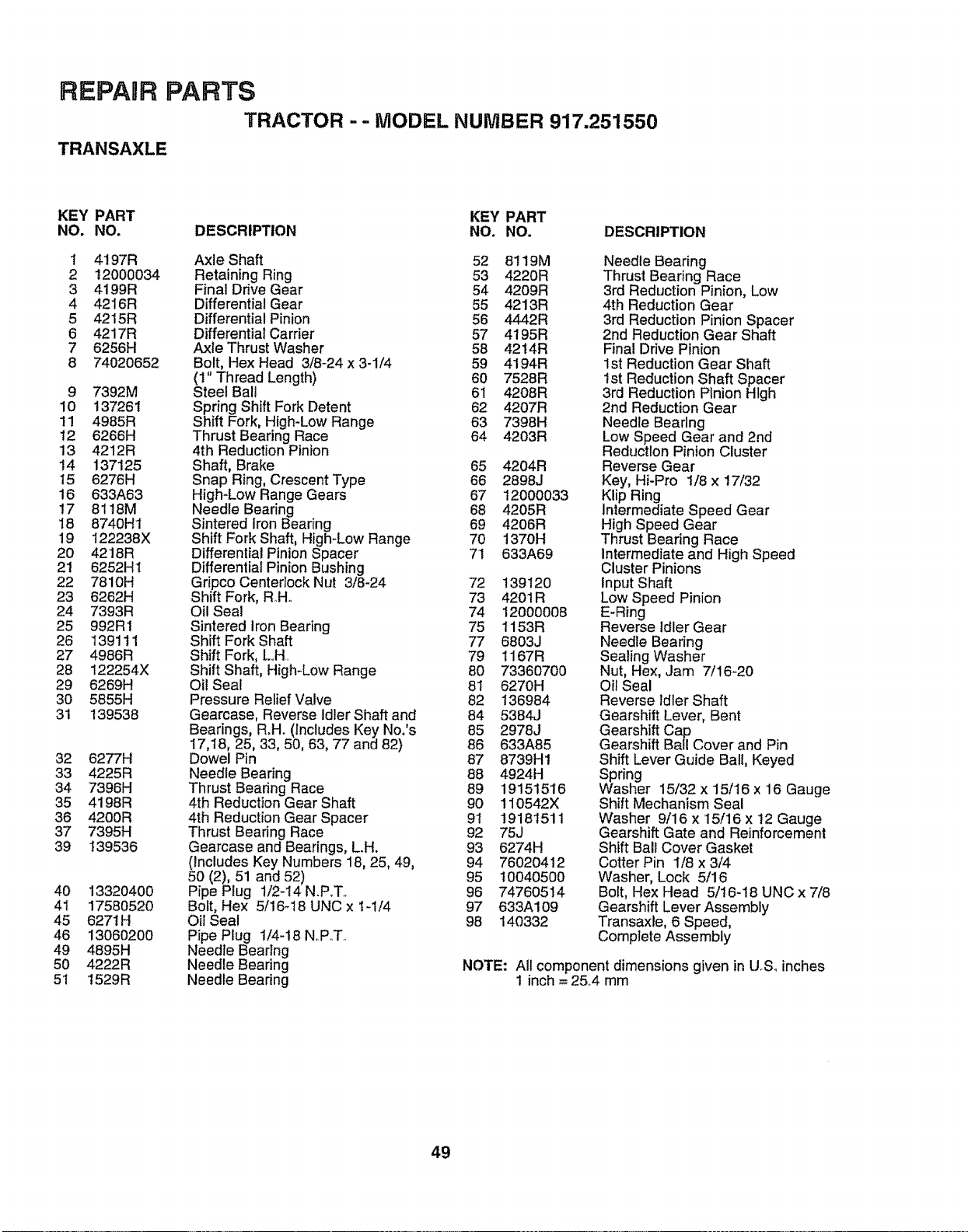
REPAUR PARTS
TRACTOR -- MODEL NUMBER 917.251550
TRANSAXLE
KEY PART KEY PART
NO. NO. DESCRIPTION NO. NO. DESCRIPTION
1 4197R Axle Shaft 52 8!19M
2 !2000034 Retaining Ring 53 4220R
3 4199R Final Drive Gear 54 4209R
4 4216R Differential Gear 55 4213R
5 4215R Differential Pinion 56 4442R
6 4217R Differential Carrier 57 4195R
7 6256H Axle Thrust Washer 58 4214R
8 74020652 Bolt, Hex Head 3/8-24 x 3-1/4 59 4194R
(1" Thread Length) 60 7528R
9 7392M Steel Ball 61 4208R
10 137261 Spring Shift Fork Detent 62 4207R
11 4985R Shift Fork, High-Low Range 63 7398H
12 6266H Thrust Bearing Race 64 4203R
13 4212R 4th Reduction Pinion
14 137125 Shaft, Brake 65 4204R
15 6276H Snap Ring, Crescent Type 66 2898J
16 633A63 High-Low Range Gears 67 12000033
17 8118M Needle Bearing 68 4205R
18 8740H1 Sintered Iron Bearing 69 4206R
19 122238X Shift Fork Shaft, High-Low Range 70 1370H
20 4218R Differential Pinion Spacer 71 633A69
21 6252H1 DifferentialPinion Bushing
22 7810H Gripco Centeriock Nut 3/8-24 72 139120
23 6262H Shift Fork, Roll. 73 4201R
24 7393R Oil Seal 74 12000008
25 992R1 Sintered iron Bearing 75 1153R
26 139111 Shift Fork Shaft 77 6803J
27 4986R Shift Fork, L..H. 79 1167R
28 122254X Shift Shaft, High-Low Range 80 73360700
29 6269H Oil Seal 81 6270H
30 5855H Pressure Relief Valve 82 136984
31 139538 Gearcase, Reverse idlerShaft and 84 5384J
Bearings, R.H. (Includes Key No.'s 85 2978J
17,18, 25, 33, 50, 63, 77 and 82) 86 633A85
32 6277H Dowel Pin 87 8739H1
33 4225R Needle Bearing 88 4924H
34 7396H Thrust Beanng Race 89 19151516
35 4198R 4th Reduction Gear Shaft 90 110542X
36 4200R 4th Reduction GearSpacer 91 19181511
37 7395H Thrust Bearing Race 92 75J
39 139536 Gearcase and Bearings, L.H. 93 6274H
(includes Key Numbers 18, 25, 49, 94 76020412
50 (2), 51 and 52) 95 10040500
40 13320400 Pipe Plug 1/2-14 N,P_T,, 96 74760514
41 17580520 Bolt, Hex 5/16-18 UNC x 1-1/4 97 633A109
45 627tH Oil Seal 98 140332
46 13060200 Pipe Plug 1/4-18 NoPoT,_
49 4895H Needle Bearing
50 4222R Needle Bearing
51 1529R Needle Bearing
Needle Bearing
Thrust Bearing Race
3rd Reduction Pinion, Low
4th Reduction Gear
3rd Reduction Pinion Spacer
2nd Reduction Gear Shaft
Final Drive Pinion
1st Reduction Gear Shaft
1st Reduction Shaft Spacer
3rd Reduction Pinion High
2nd Reduction Gear
Needle Bearing
Low Speed Gear and 2nd
Reduction Pinion Cluster
Reverse Gear
Key, Hi-Pro 1/8 x 17/32
Klip Ring
Intermediate Speed Gear
High Speed Gear
Thrust Bearing Race
Intermediate and High Speed
Cluster Pinions
input Shaft
Low Speed Pinion
E-Ring
Reverse Idler Gear
Needle Bearing
Sealing Washer
Nut, Hex, Jam 7/16-20
Oil Seal
Reverse idler Shaft
Gearshift Lever, Bent
Gearshift Cap
Gearshift Ball Cover and Pin
Shift Lever Guide Bali, Keyed
Spring
Washer 15/32 x 15/16 x 16 Gauge
Shift Mechanism Seal
Washer 9/16 x 15/16 x 12 Gauge
Gearshift Gate and Reinforcement
Shift Bali Cover Gasket
Cotter Pin 1/8 x 3/4
Washer, Lock 5/16
Bolt, Hex Head 5/16-!8 UNC x 7/8
Gearshift Lever Assembly
Transaxle, 6 Speed,
Complete Assembly
NOTE: All component dimensions given in USo inches
1 inch = 2&4 mm
49
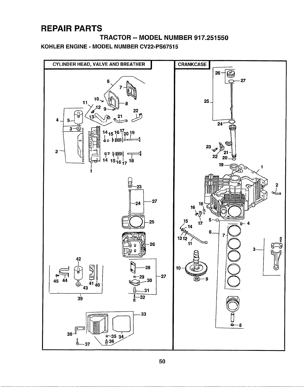
REPAIR PARTS
TRACTOR -- MODEL NUMBER 917.251550
KOHLER ENGINE - MODEL NUMBER CV22-PS67515
CYLINDER HEAD, VALVE AND BREATHER I
4_
11
141s16+_20.19
14 151617 18
42
45 44
43 0
[
39
_'-'23
_27
18
_-9
©
3_
2
Y
50
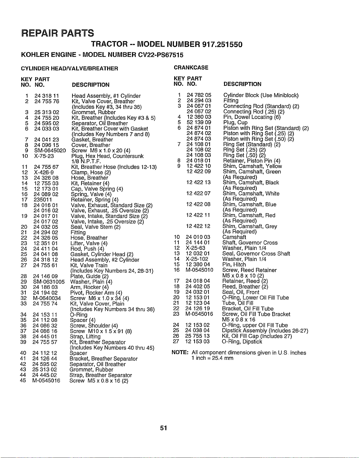
REPAIR PARTS
TRACTOR -- MODEL NUMBER 917.251550
KOHLER ENGINE - MODEL NUMBER CV22-PS67515
CYLINDER HEAD/VALVE/BREATHER
CRANKCASE
KEY PART KEY PART
NO. NO. DESCRIP_ON NO. NO. DESCRIPTION
1 2431811
2 24 755 76
3 25 31302
4 24 755 2O
5 24 595 02
6 24 033 03
7 24 04t 23
8 24 096 15
9 SM-0645020
10 X-75-23
11 24 755 67
12 X-426-9
13 24 326 08
14 12 755 03
15 12 173 01
16 24 089 02
17 235011
18 24 0t6 01
24 016 02
19 24 017 01
24 017 02
20 24 032 05
2t 24 294 02
22 24 326 05
23 12 351 01
24 24 411 04
25 24 041 08
26 24 318 12
27 24 755 61
28 24 146 09
29 SM-0631005
30 24 186 03
31 24 194 02
32 M-0640034
33 24 755 74
34 24 15311
35 24 112 O8
36 24 086 32
37 24 086 16
38 24 445 01
39 24 755 57
Head Assembly, #t Cylinder
Kit, Valve Cover, Breather
(includes Key #3, 34 thru 36)
Grommet, Rubber
Kit, Breather (Includes Key #3 & 5)
Separator, Oil Breather
Kit, Breather Cover with Gasket
(Includes Key Numbers 7 and 8)
Gasket, Breather
Cover, Breather
Screw M6 x 1..0x 20 (4)
Plug, Hex Head, Countersunk
1/8 NoP.T.F.
Kit, Breather Hose (Includes 12-13)
Clamp, Hose (2)
Hose, Breather
Kit, Retainer (4)
Cap, Valve Spring (4)
Spring, Valve (4)
Retainer, Spring (4)
Valve, Exhaust, Standard Size (2)
Valve, Exhaust, .25 Oversize (2)
Valve, Intake, Standard Size (2)
Valve, Intake, .25 Oversize (2)
Seal, Valve Stem (2)
Fitting
Hose, Breather
Lifter, Valve (4)
Rod, Push (4)
Gasket, Cylinder Head (2)
Head Assembly, #2 Cylinder
Kit, Valve Train
(includes Key Numbers 24, 28-31)
Plate, Guide (2)
Washer, Plain (4)
Arm, Rocker (4)
Pivot, Rocker Arm (4)
Screw M6 x 1.0 x 34 (4)
Kit, Valve Cover, Plain
(Includes Key Numbers 34 thru 36)
O-Ring
Spacer (4)
Screw, Shoulder (4)
Screw MIO x 1.5 x 91 (8)
Strap, Lifting
Kit, Breather Separator
(Includes Key Numbers 40 thru 45)
Spacer
Bracket, Breather Separator
Separator, Oil Breather
Grommet, Rubber
Strap, Breather Separator
Screw M5 x OB x 16 (2)
40 24 112 12
41 24 126 44
42 24 595 02
43 25 313 02
44 24 44502
45 M-0545016
1 24 782 05
2 24 294 03
3 24 067 0!
24 067 02
4 12 380 03
5 52 t39 09
6 24 87401
24 874 02
24 874 03
7 24 108 0t
24 108 02
24 108 03
8 24 018 01
9 12 422 10
12 422 09
12 422 13
12 422 07
12 422 08
12 422 11
12 42212
10 24 010 03
11 24 144 01
12 X-25-63
13 12 032 01
14 X-25-102
15 12 380 04
16 M-0545010
I7 24 018 04
18 24 402 O5
19 24 032 01
20 12 153 01
21 12 t23 04
22 24 12619
23 M-0545016
24 12 153 02
25 24 038 04
26 25 755 13
27 12 153 03
Cylinder Block (Use Miniblock)
Fitting
Connecting Rod (Standard) (2)
Connecting Rod (25) (2)
Pin, Dowel Locating (6)
Plug, Cup
Piston with Ring Set (Standard) (2)
Piston with Ring Set (°25) (2)
Piston with Ring Set (.50) (2)
Ring Set (Standard) (2)
Ring Set (.25) (2)
Ring Set (.50) (2)
Retainer, Piston Pin (4)
Shim, Camshaft, Yellow
Shim, Camshaft, Green
(As Required)
Shim, Camshaft, Black
(As Required)
Shim, Camshaft, White
(As Required)
Shim, Camshaft, Blue
(As Required)
Shim, Camshaft, Red
(As Required)
Shim, Camshaft, Grey
(As Required)
Camshaft
Shaft, Governor Cross
Washer, Plain 1/4
Seal, Governor Cross Shaft
Washer, Plain 1/4
Pin, Hitch
Screw, Reed Retainer
M5 x 0.8 x 10 (2)
Retainer, Reed (2)
Reed, Breather (2)
Seat, Oil, Front
O-Ring, Lower Oil Fill Tube
Tube, Oil Fill
Bracket, Oil Fill Tube
Screw, Oil Fill Tube Bracket
M5xOSx 16
O-Ring, upper Oil Fill Tube
Dipstick Assembly (Includes 26-27)
Kit, Oil Fill Cap (Includes 27)
O-Ring, Dipstick
NOTE: All component dimensions given in U.S. inches
1 inch= 25.4 mm
51
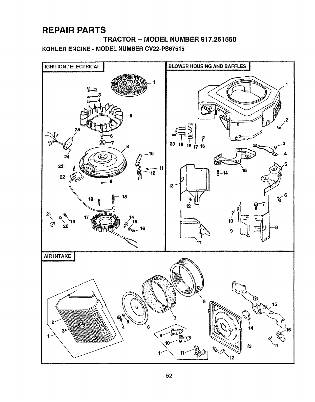
REPAIR PARTS
TRACTOR - MODEL NUMBER 917.251550
KOHLER ENGINE - MODEL NUMBER CV22-PS67515
_-.2
_..__3
_B-.--4
25_ 5
10
17
4 6
BLOWER HOUSING AND BAFFLES I
20 19 1 16
i
13f
12
1t
--8
7
15
16
52
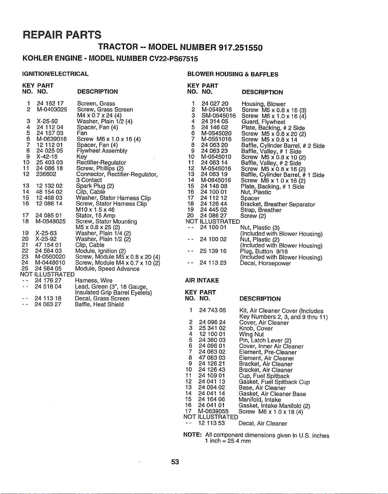
REPARR PARTS
TRACTOR -- MODEL NUMBER 917,251550
KOHLER ENGINE - MODEL NUMBER CV22-PS67515
IGNITION/ELECTRICAL
BLOWER HOUSING & BAFFLES
KEY PART KEY PART
NO. NO. DESCRIPTION NO. NO.
1
2
3
4
5
6
7
8
9
10
11
12
t3
14
15
16
17
18
24 162 17 Screen, Grass 1 24 027 20
M-0403025 Screw, Grass Screen 2 M-0549016
M4 x 0..7 x 24 (4) 3 SM-0645016
X-25-92 Washer, Plain 1/2 (4) 4 24 314 05
24 112 04 Spacer, Fan (4) 5 24 146 02
24 157 03 Fan 6 M-0545020
M-06390t6 Screw M6 x 1.0 x 16 (4) 7 M-0551016
12 112 01 Spacer, Fan (4) 8 24 063 20
24 025 05 Flywheel Assembly 9 24 063 23
X-42-15 Key 10 M-0545010
25 403 03 Rectifier-Regulator 11 24 063 14
24 086 18 Screw, Phillips (2) 12 M-0545016
236602 Connector, Rectifier-Regulator, 13 24 063 19
3 Contact 14 M-0645016
12 132 02 Spark Plug (2) t5 24 146 08
48 154 02 Clip, Cable 16 24 t00 01
12 468 03 Washer, Stator Harness Clip 17 24 ! 12 12
12 086 14 Screw, Stator Harness Clip 18 24 !26 44
M10x1.5x46 19 2444502
24 085 01 Stator, 15 Amp 20 24 086 27
M-0548025 Screw, Stator Mounting NOT
M5 x 0.8 x 25 (2) - -
X-25-63 Washer, Plain 1/4 (2)
X-25_92 Washer, Plain I/2 (2) - -
47 154 01 Clip, Cable
24 584 03 Module, Ignition (2) - _
M-0560020 Screw, Module M5 x 0.8 x 20 (4)
M-0448010 Screw, Module M4 x 0_7 x 10 (2) - -
24 584 05 Module, Speed Advance
ILLUSTRATED
24 176 27 Harness, Wire
- _ 24 518 04 Lead, Green (3", 18 Gauge,
Insulated Grip Barrel Eyelets)
- - 24 113 18 Decal, Grass Screen
- - 24 063 27 Baffle, Heat Shield
19
20
21
22
23
24
25
NOT
DESCRIPTION
Housing, Blower
Screw M5 x 0.8 x 16 (3)
Screw M6 x 1o0x 16 (4)
Guard, Flywheel
Plate, Backing, # 2 Side
Screw M5 x 0o8x 20 (2)
Screw M5 x 0.8 x 14
Baffle, Cylinder Barrel, # 2 Side
Baffle, Valley, # I Side
Screw M5 x 0.8 x 10 (2)
Baffle, Valley, # 2 Side
Screw M5 x 0.8 x 16 (2)
Baffle, Cylinder Barrel, # 1 Side
Screw M6 x t _0x 16 (2)
Plate, Backing, # 1 Side
Nut, Plastic
Spacer
Bracket, Breather Separator
Strap, Breather
Screw (2)
ILLUSTRATED
24 100 01 Nut, Plastic (3)
(Included with Blower Housing)
24 100 02 Nut, Plastic (2)
(Included with Blower Housing)
25 139 16 Plug, Button 9/16
(Included with Blower Housing)
24 113 23 Decal, Horsepower
AIR INTAKE
KEY PART
NO. NO. DESCRIPTION
24 743 05
2 24 096 24
3 25 341 02
4 12 100 01
5 24 38003
6 24096 01
7 24 083 02
8 47 083 03
9 24 126 21
10 24 126 43
11 24 109 01
12 24 041 13
13 24 094 02
14 24 041 14
15 24 164 06
16 24 041 01
17 M-0639055
NOT
Kit, Air Cleaner Cover (includes
Key Numbers 2, 3, and 9 thru 11)
Cover, Air Cleaner
Knob, Cover
Wing Nut
Pin, Latch Lever (2)
Cover, Inner Air Cleaner
Element, Pre-Cleaner
Element, Air Cleaner
Bracket, Air Cleaner
Bracket, Air Cleaner
Cup, Fuel Spitback
Gasket, Fuel Spitback Cup
Base, Air Cleaner
Gasket, Air Cleaner Base
Manifold, Intake
Gasket, Intake Manifold (2)
Screw M6 x 1.0 x I8 (4)
ILLUSTRATED
12 113 53 Decal, Air Cleaner
NOTE: All component dimensions given in U.S. inches
1 inch = 25,4 mm
53
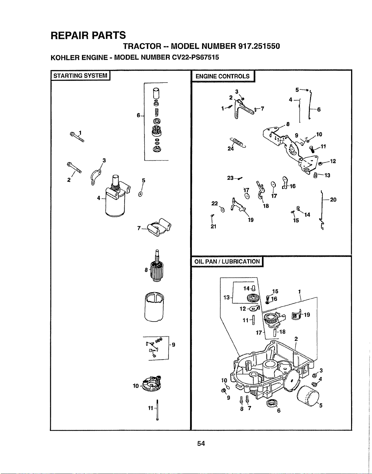
REPAIR PARTS
TRACTOR--MODEL NUMBER 917.251550
KOHLER ENGINE - MODEL NUMBER CV22-PS67515
i
STARTING SYSTEM I
%
3
/
_
ENGINE CONTROLS I
3
2,
i.-._
10
22
1"
21
23--,-
19
18
12 __\_i-- _ _ i
8 7 6
54
REPAIR PARTS
TRACTOR -- MODEL NUMBER 917,251550
KOHLER ENGINE - MODEL NUMBER CV22-PS67515
STARTING SYSTEM
ENGINE CONTROLS
KEY PART KEY PART
NO. NO, DESCRIPTION NO. NO.
1 M_0839070 Screw M8 x 1o25x 70
2 M-0839080 Screw M8 x 1.25 x 80
3 24 096 05 Cover, Pinion
4 25 098 03 Starter Assembty (Includes 6-11)
5 12 468 01 Washer (3)
6 12 755 54 Kit, Drive End
7 1222706 Cap, Drive End
8 45 170 03 Armature
9 82 755 28 Kit, Brush and Spring
10 12 227 11 Cap, Commutator End
11 12 086 25 Bolt, Thru (2)
OIL PAN/LUBRICATION
DESCRIPTION
KEY PART
NO. NO.
Oil Pan Assembly
Oil Pan
Plug, Hex, Countersunk,
3/8 N.P.T F.
Nipple, Oil Fiiter
Filter, Oil
Seal, Oil (PTO End)
Screw, Oil Pan M8 x 1.25 x 45
Screw, Oi! Pan M8 x 125 x 45 (9)
Plug, Solid, Square Head,
3/8 N_P.T_F_
O-Ring
Shaft, Governor Gear
Tab, Locking
Kit, Governor Gear with Pin
(Includes Key Number t4)
Pin, Governor Regulating
Screw M6 x 10 x 25 (2)
Washer, Plain (2)
Oil Pump Assembly (includes 18)
Tube, Oil Pickup
Screen, Oil
1 24 199 07
2 24 199 04
3 X-75-32
4 24 136 01
5 12 050 01
6 52 032 08
7 24 086 17
8 24 086 16
9 X-75-10
10 24 153 08
I1 12 144 02
12 52 448 02
13 24 043 12
14 12 380 01
15 M-0645025
16 SM-0631005
17 24 393 08
18 24 123 05
19 25 162 07
DESCRIPTION
1 SM-0642025 Screw M6x1Ox25
2 24090 14 Lever, Governor
3 SM-0641060 Nut M6x 1.0
4 24 089 01 Spring, Linkage
5 25 158 08 Bushing, Linkage Retaining
6 24 079 04 Linkage, Throttle
7 25 158 11 Bushing, Throttle Linkage
8 24 126 13 Bracket, Control
9 24 089 03 Spring, Choke Return
10 M-0547050 Locknut, Hex M5 x08
1! SM-0545016 Screw M5x0.Sx16
t2 M-0446030 Nut, Hex M4 x 0o7
13 SM-0645016 Screw M6x1_0x18(4)
14 12 237 01 Clamp, Cable (2)
15 SM-0545016 Screw M5 x 0o8X 16 (2)
16 24 090 07 Lever, Throttle Actuator
17 24 468 01 Washer (3)
18 24 090 13 Lever, Throttle Control
19 24 090 05 Lever, Choke
20 24 079 05 Linkage, Choke
21 SM-0545020 Screw M5 x 0°8 x 20
22 41 468 03 Washer, Wave
23 M-0403025 Screw M4 x 0_7x 24
24 24 089 18 Spring, Governor
NOTE: All component dimensions given in U S inches
1 inch = 25.4 mm
55
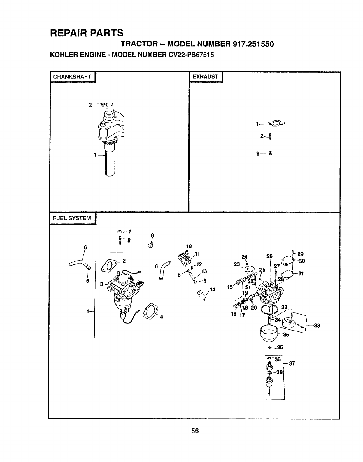
REPAIR PARTS
TRACTOR -- MODEL NUMBER 917.251550
KOHLER ENGINE - MODEL NUMBER CV22-PS67515
2--_
6
5
_-_7
9
p8
10
_12
/14
24
23
16 17
0----36
i- -- 37
38
-3 €.
56
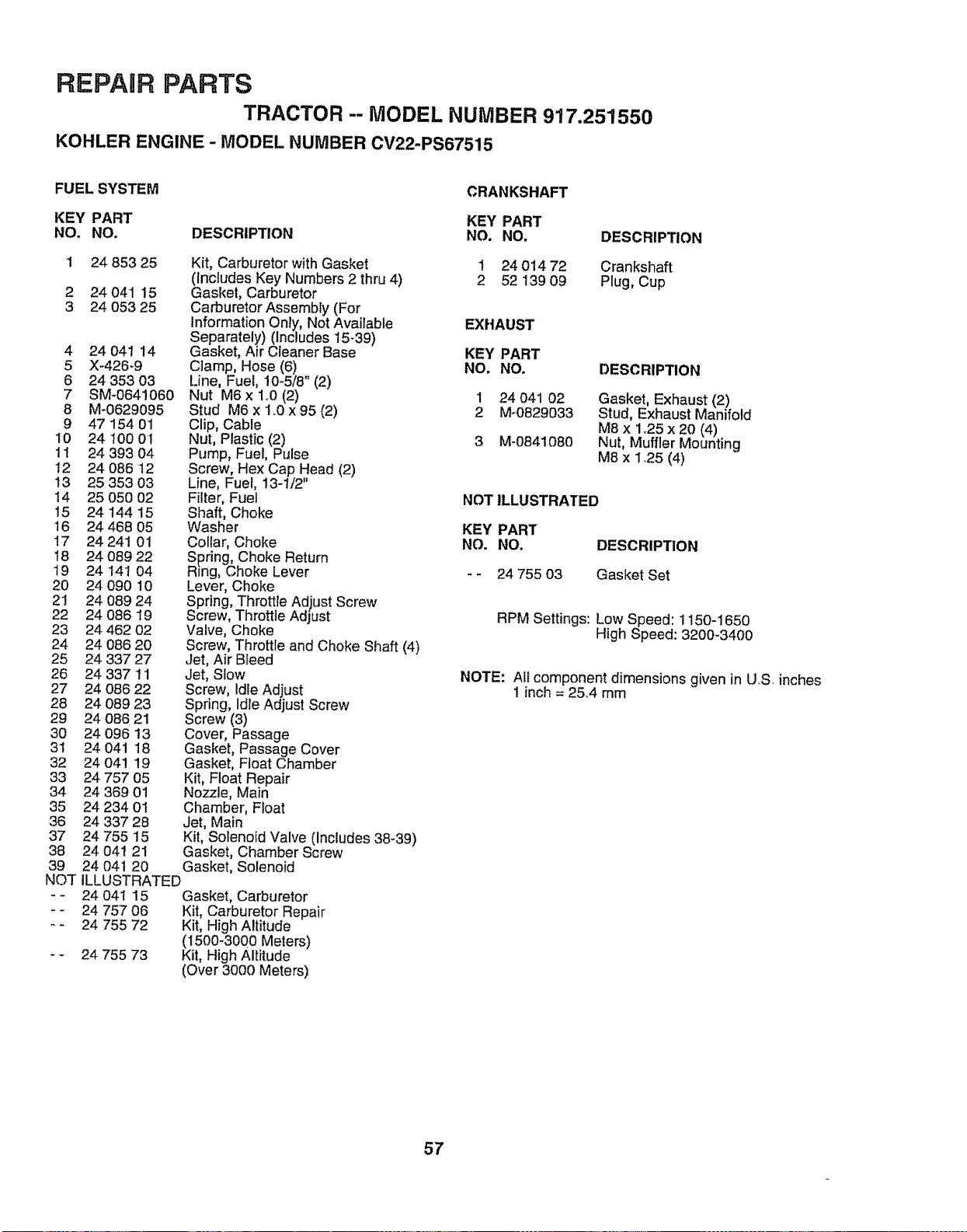
REPAIR PARTS
TRACTOR -- MODEL NUMBER 917.251550
KOHLER ENGINE - MODEL NUMBER CV22-PS67515
FUEL SYSTEM
KEY PART
NO. NO. DESCRIPTION
1 24 853 25
2 24 04'1 15
3 24 053 25
4 24 041 t4
5 X-426-9
6 24 353 03
7 SM-064!060
8 M-0629095
9 47154 01
10 24 100 01
11 24 393 04
12 24 086 12
13 25 353 03
14 25 050 02
15 24 144 15
16 24 468 05
17 24 241 01
18 24 089 22
t9 24141 04
20 24 090 10
2! 24 089 24
22 24 086 t9
23 24 462 02
24 24 086 20
25 24 337 27
26 24 337 !'1
27 24 086 22
28 24 089 23
29 24 086 21
30 24 096 13
31 24 041 18
32 24 041 19
33 24 757 05
34 24 369 01
35 24 234 01
36 24 337 28
37 24 755 15
38 24 041 21
39 24 041 20
NQT
_w
Kit, Carburetor with Gasket
(Includes Key Numbers 2 thru 4)
Gasket, Carburetor
Carburetor Assembly (For
Information Only, Not Available
Separately) (Includes 15_39)
Gasket, Air Cleaner Base
Clamp, Hose (6)
Line, Fuel, 10-5/8" (2)
Nut M6 x 140(2)
Stud M6 x 1,.0x 95 (2)
Clip, Cable
Nut, Plastic (2)
Pump, Fuel, Pulse
Screw, Hex Cap Head (2)
Line, Fuel, 13-1/2"
Filter, Fuel
Shaft, Choke
Washer
Collar, Choke
Spring, Choke Return
Rtng, Choke Lever
Lever, Choke
Spring, Throttle Adjust Screw
Screw, Throttle Adjust
Valve, Choke
Screw, Throttle and Choke Shaft (4)
Jet, Air BIeed
Jet, Slow
Screw, Idle Adjust
Spring, Idle Adjust Screw
Screw (3)
Cover, Passage
Gasket, Passage Cover
Gasket, Float Chamber
Kit, Float Repair
Nozzle, Main
Chamber, Float
Jet, Main
Kit, Solenoid Valve (Includes 38-39)
Gasket, Chamber Screw
Gasket, Solenoid
ILLUSTRATED
24 04t 15 Gasket, Carburetor
24 757 06 Kit, Carburetor Repair
24 755 72 Kit, High Altitude
(1500-3000 Meters)
24 755 73 Kit, High Altitude
(Over 3000 Meters)
CRANKSHAFT
KEY PART
NO. NO,
1 24 01472
2 52 139 09
DESCRIPTION
Crankshaft
Plug, Cup
EXHAUST
KEY PART
NO, NO. DESCRIPTION
1 24 041 02 Gasket, Exhaust (2)
2 M-0829033 Stud, Exhaust Manifold
M8 x 1°25 x 20 (4)
3 M_0841080 Nut, Muffler Mounting
1'918x 1,25 (4)
NOT ILLUSTRATED
KEY PART
NO. NO. DESCRIPTION
- - 24 755 03 Gasket Set
RPM Settings: Low Speed: 1150-1650
High Speed: 3200-3400
NOTE: All component dimensions given in US, inches
1 inch = 25,4 mm
57

SERVICE NOTES
58

SUGGESTED GUIDE FOR SiGHTiNG SLOPES FOR SAFE OPERATION
(j1
LO
SIGHTING "" --- ..,CUT
GUIDE TH_
ONLY RIDE UP AND DOWN HILL,
NOT ACROSS HILL
SIGHT AND HOLD THIS LEVEL WITH
SKY LINE OR TREE.
15° MAX.
IIHIIII I IIIIIIIIII .... IIIIIIIIII IIIIIII rr
I!
Operate your Tractor up and down the face of slopes (not I
greater than 15°), never across the face. Make turns gradu-
ally to prevent tipping or loss of control. Exercise extreme I
caution when changing direction on slopes.
I

OWNER'S
MANUAL
MODEL NO.
917.251550
IF YOU NEED
REPAIR SERVICE
OR PARTS:
FOR REPAIR SERVICE, CALL
THIS TOLL FREE NUMBER:
1-800-4-REPAIR
(1-800-473-7247)
FOR REPLACEMENT PARTS
INFORMATIONAND
ORDERING, CALL THIS
TOLL FREE NUMBER:
1-800-FON-PART
(1-800-366-7278)
MI:IN®
22.5 HP TWIN CYLINDER
ELECTRIC START
50" MOWER
6 SPEED TRANSAXLE
GARDEN TRACTOR
Each tractor has its own model number. Each engine has
its own model number:
The model number for your tractor will be found on the
mode! plate located under the seat.
The model number for your engine will be found on the
blower housing of the engine.
All parts listed herein may be ordered from arty Sears,
Roebuck and Co,. Service Center/Department and most Re-
tail Stores.
WHEN ORDERING REPAIR PARTS, ALWAYS GIVE THE
FOLLOWING INFORMATION:
" PRODUCT - TRACTOR
• MODEL NUMBER - 917.251550
• ENGINE MODEL NO, - 0V22-67515
- PART NUMBER
• PART DESCRIPTION
Your Sears merchandise has added value when you
consider Sears has service units nationwide staffed with
Sears trained technicians ..... professional technicians
specifically trained to insure that we meet our pledge to
you, we service what we see
IIIIIIIII
151604 Rev. 1 0&20_96 RH
IIIIIIII IIIIIIIIIIIIIIIIIIIIIIIIIIIIIII11111111111111111111111111111111111
Printed in U,,S.A.


