Loading ...
Loading ...
Loading ...
Installation instructions
iiiiiiiiiiiiii iiiiiiiiiiiii
iNSTALLING THE WATER LINE (CONT.)
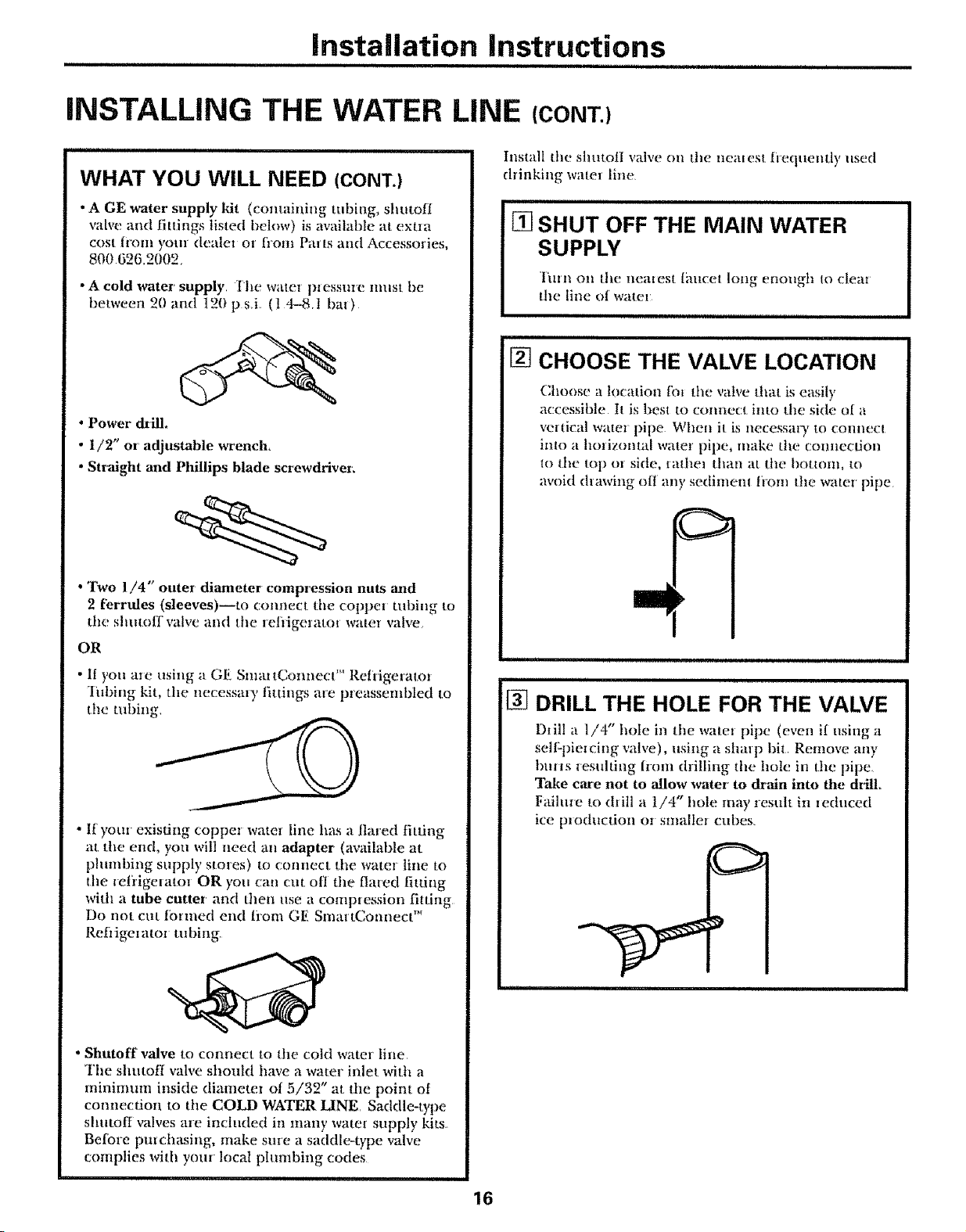
WHAT YOU WILL NEED (CONT.)
"A GE water supply ldt (containing tubing, slmtofI
vah,e and lillings listed below) is available at extra
cosl hom yore dealer ol tiom Pints and Accessories,
800 626.2002.
• A cold water' supply, lhe warm piessme inust be
between 211and 120 t) s,i, (1 4-81 bin)
• Power drill
• 1/2" or adjustable wrench,
, Straight and Phillips blade screwdriver,
• Two 1/4" outer diameter-compression nuts and
2 [errules (sleeves)--to connect the coppel tubing to
the shulolrvalve and lt_e _eliigeratol warm valve_
OR
• It you me using a GE Sm,u tConnect Retrigelatoz
Iid)ing kit, the necessmy fittings are preassembled to
the mbing
• lfyom existing coppm wate_ line has a llared fitting
at. tile end, you will need an adapter (available at
phmlbing supply stores) m connect tim water line to
the ve!'rigetamt OR you can cut oil ttle flayed fitting
with a tube cutter and then use a compression fitting
Do not cut ibtmed end liom GE Stoat tConnect"
Refiigmatol robing
, Shutoff valve to connect to tile cold water line
The shutoII wflve should have a water inlet with a
minimum inside diametel of 5/32" at die point o[
connecdoll to tile COLD WATER LINE. Saddle-type
shuto{t valves me included in many water supply kits.
Belore pmchasing, make sllve a saddle-type valve
complies with you! local phmlbing codes
Install the shmoll vah,e on the neat est hequently used
drinking warm line.
,i,ii1,1111111i, iii ii iii iii i i
[] SHUT OFF THE MAIN WATER
SUPPLY
linn on tile nea,est [aucet long enough to cleat
the line of water
iiiii iiiii iiiii illu,
[] CHOOSE THE VALVE LOCATION
Choose a location Ibm tile vah,e that is easily
accessible It is best to connect into the side oI a
vertical wate_ pipe When il is necessm T to connect
into a hofizomal water l)ipe, make the CollneclJOll
{o the lop t)_ side, rathe_ than at tim bottOIll, 10
avoid drawing o{I any sediment tiom the ware1 pipe
i
[] DRILL THE HOLE FOR THE VALVE
Drill a 1/4" hole i,l the wate, pipe (even il using a
self pier cing valve), vsing a sharp bit Remove any
t)mxs lesulting irom drilling the hole in tim pipe,
Take care not to allow water to drain into the drill°
Failure to dlitl a 1/4" hole may resuh in ,educed
ice production o_ smallm cubes.
16
Loading ...
Loading ...
Loading ...