Loading ...
Loading ...
Loading ...
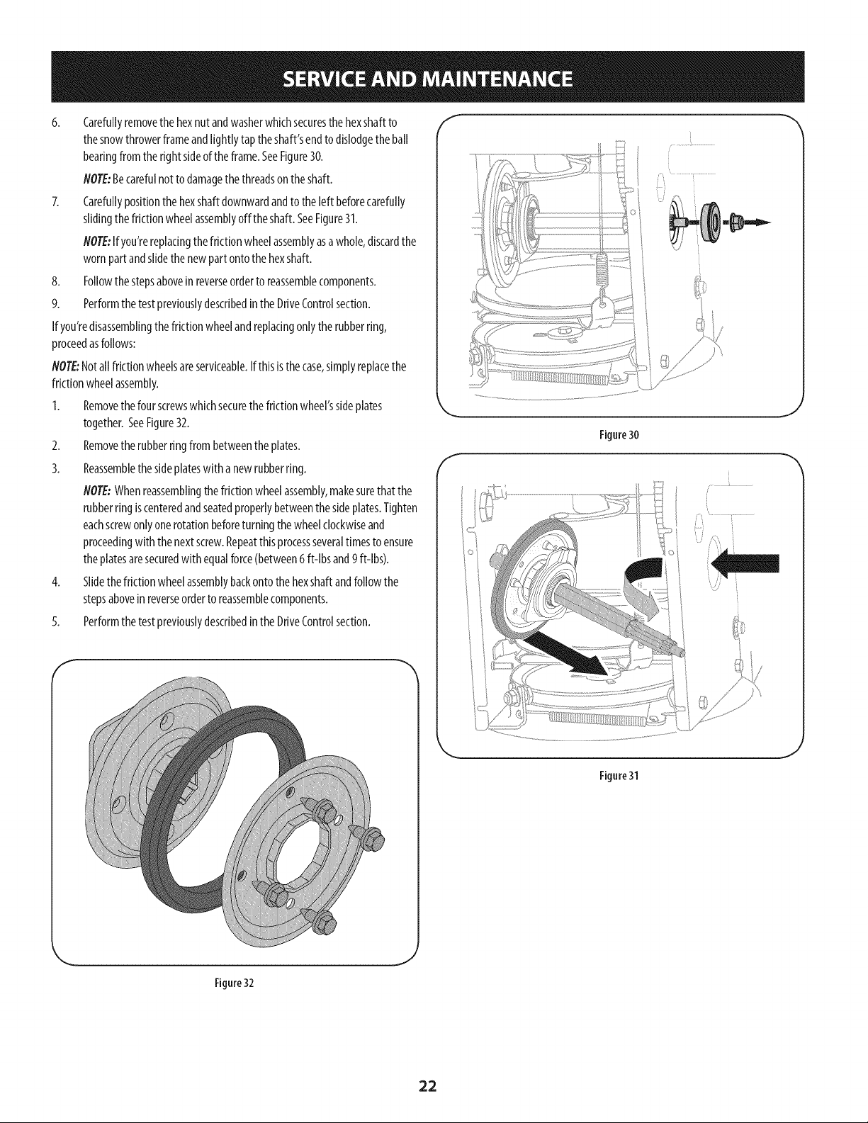
6. Carefullyremovethe hexnut andwasherwhichsecuresthe hexshaftto
thesnowthrowerframeandtightlytap theshaft'sendto dislodgethe ban
bearingfromthe rightsideofthe frame.SeeFigure30.
NOTE:Becarefulnotto damagethe threadsontheshaft.
7. Carefullypositionthe hexshaftdownwardandto the[eft beforecarefuNy
slidingthefrictionwheelassemblyoff the shaft.SeeFigure31.
NOTE:If you'rereplacingthe frictionwheelassemblyasawhole,discardthe
wornpartandslidethe newpartontothe hexshall
8. FoNowthestepsabovein reverseorderto reassemblecomponents.
9. Performthe test previouslydescribedintheDriveControlsection.
Ifyou'redisassemblingthe frictionwheelandreplacingonlytherubberring,
proceedasfollows:
NOTE:Notallfrictionwheelsareserviceable.If thisisthe case,simplyreplacethe
frictionwheelassembly.
1. Removethefour screwswhichsecurethe frictionwheel'ssideplates
together.SeeFigure32.
2. Removethe rubberringfrombetweenthe plates.
3. Reassemblethesideplateswith anewrubberring.
NOTE:Whenreassemblingthefriction wheelassembly,makesurethat the
rubberringiscenteredandseatedpropertybetweenthe sideplates.Tighten
eachscrewonlyonerotationbeforeturningthewheelclockwiseand
proceedingwith thenextscrew.Repeatthis processseveraltimesto ensure
theplatesaresecuredwith equalforce(between6ft-[bsand9ft-[bs).
4. Slidethe frictionwheelassemblybackontothehexshaftandfoNowthe
stepsabovein reverseorderto reassemblecomponents.
5. Performthe test previouslydescribedintheDriveControlsection.
f
f
Figure30
J
Figure31
J
Figure 32
,J
22
Loading ...
Loading ...
Loading ...