Loading ...
Loading ...
Loading ...
EN-6 452163.66.10 · FD 9506 www.dimplex.de
English
LA 17TU - LA 40TU
6Assembly
6.1 General
The following connections need to be established on the heat
pump:
Heating system flows and returns
Condensate outflow
Control line to the heat pump manager
Power supply
6.2 Connection on heating side
The heating system connections on the heat pump are to be
made inside the device. Refer to the device information for the
connection sizes. Route the connection hoses out of the device
in a downwards direction. An optional pipe kit is available as an
accessory, which can be used to lead the connections out to the
side.
Use a spanner to firmly grip the transitions when connecting the
heat pump.
Before connecting the heating water system to the heat pump,
the heating system must be flushed to remove any impurities, re-
sidue from sealants, etc. Any accumulation of deposits in the li-
quefier could cause the heat pump to completely break down.
ATTENTION!
The dirt trap included in the scope of supply is to be installed in the heat
return before the heat pump.
Cleaning and maintenance instructions can be found in the dirt
trap's installation and operating instructions.
Once the heat pump has been connected to the heating system,
it must be filled, de-aerated and pressure-tested.
Consideration must be given to the following when filling the sys-
tem:
Untreated filling water and make-up water must be of drink-
ing water quality (colourless, clear, free from sediments)
Filling water and make-up water must be pre-filtered (pore
size max. 5µm).
Scale formation in hot water heating systems cannot be comple-
tely avoided, but in systems with flow temperatures below 60°C
the problem can be disregarded.
With medium and high-temperature heating systems, tempera-
tures above 60 °C can be reached..
The following standard values should therefore be adhered to
concerning the filling water and make-up water (according to VDI
2035 Sheet 1):
Minimum heating water flow
The minimum heating water flow rate through the heat pump
must be assured in all operating states of the heating system.
This can be accomplished, for example, by installing either a dual
differential pressureless manifold or an overflow valve. The pro-
cedure for setting an overflow valve is described in the chapter
"Start-up". When the minimum heating water flow rate is under-
shot, the plate heat exchanger in the refrigeration circuit can
freeze, which can lead to total loss of the heat pump.
The nominal flow rate is specified depending on the max. flow
temperature in the device information and must be taken into ac-
count during planning. With design temperatures below 30 C in
the flow, the design must be based on the max. volume flow with
5 K spread for A7/W35.
NOTE
The use of an overflow valve is only recommended for panel heating and
a max. heating water flow of 1.3 m³/h. System faults may result if this is
not observed.
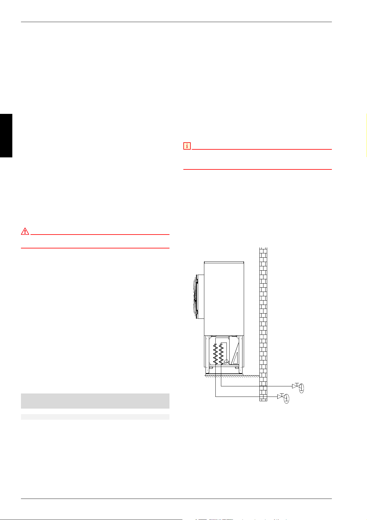
Antifreeze
Heat pump systems, which cannot be guaranteed to be frostfree,
should be equipped with a drainage option (see Fig.). The anti-
freeze function of the heat pump manager is active whenever the
manager and the heat circulating pump are ready for operation.
The system has to be drained if the heat pump is taken out of ser-
vice or in the event of a power failure. The heating circuit should
be operated with a suitable antifreeze if heat pump systems are
implemented in buildings where a power failure cannot be detec-
ted (holiday home).
Total heat
output in [kW]
Total alkaline earths
in mol/m³ and/or
mmol/l
Total
hardness in °dH
up to 200
2.0 11.2
200 to 600
1.5 8.4
> 600 < 0.02 < 0.11
Loading ...
Loading ...
Loading ...