Loading ...
Loading ...
Loading ...
EN-4 452163.66.10 · FD 9506 www.dimplex.de
English
LA 17TU - LA 40TU
3 Scope of supply
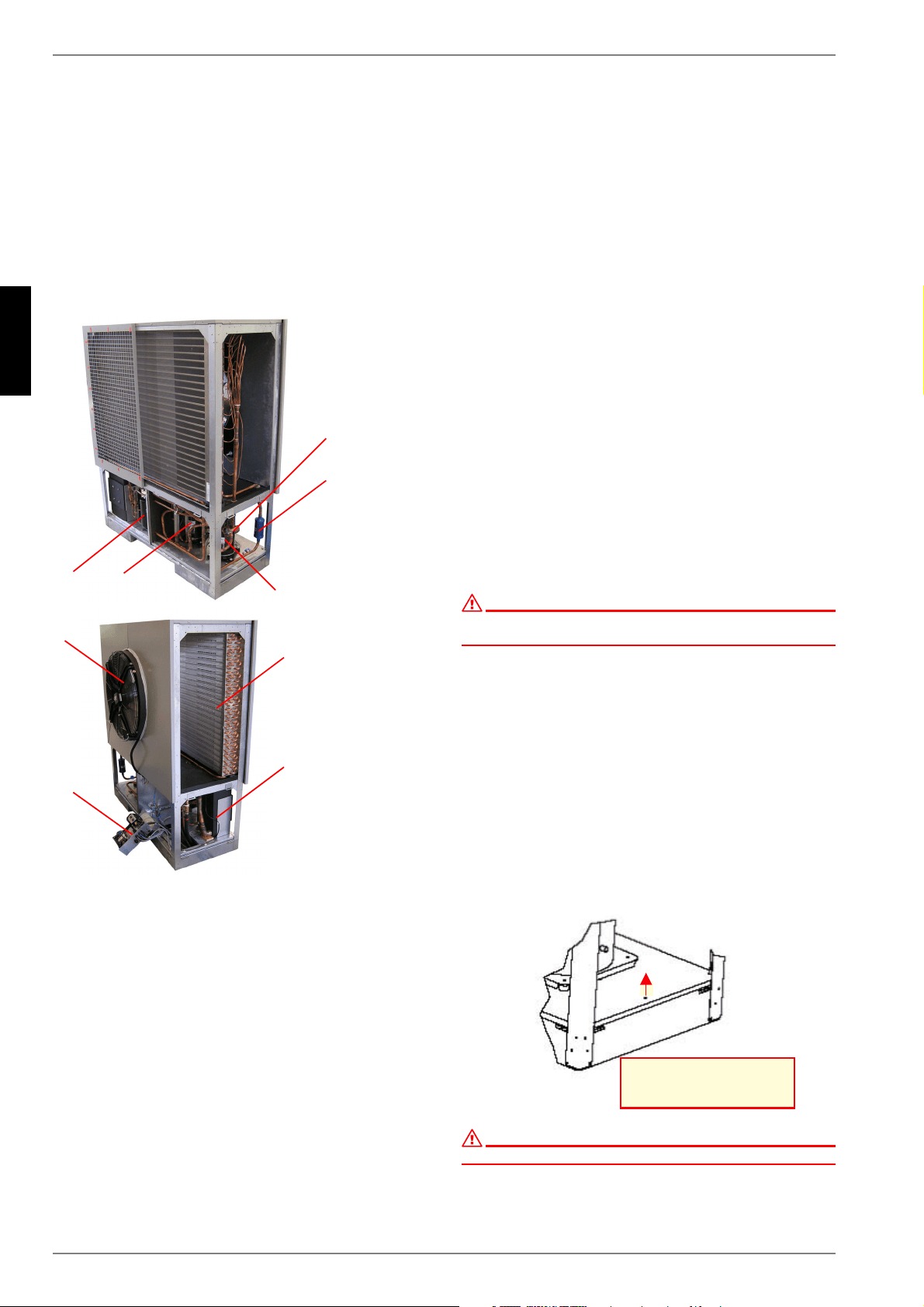
3.1 Basic device
The heat pump contains the components listed below.
The refrigerant circuit is hermetically sealed. It contains the
Kyoto protocol approved fluorinated refrigerant R404A with a
GWP value of 3922. It is CFC-free, non-ozone depleting and
non-combustible.
1) Evaporator
2) Liquefier
3) Ventilator
4) Switch box
5) Compressor 1
6) Compressor 2
7) Filter dryer
8) Expansion valve
9) Collector
3.2 Switch box
The switch box is located in the heat pump. It can be swung out
after removing the lower front cover and loosening the fastening
screw located in the upper right-hand corner.
The switch box contains the supply connection terminals as well
the power contactors and the soft starter unit.
The plug connectors for the control line are located on the switch
box panel near the pivotal point.
3.3 Heat pump manager
Use the heat pump manager included in the scope of supply to
operate the air-to-water heat pump.
The heat pump manager is a convenient electronic regulation
and control device. It controls and monitors the entire heating
system based on the external temperature, as well as domestic
hot water preparation and safety systems.
The customer must install the external temperature sensor,
which is included in the scope of supply of the unit heat pump
and manager together with the necessary fixing accessories.
The enclosed operating instructions describe the function and
use of the heat pump manager.
4 Transport
ATTENTION!
When transporting the heat pump, ensure that it is not tilted more than
45° (in any direction).
A pallet should be used to transport the heat pump to its final in-
stallation location. The heat pump is fixed to the transport pallet
by four transit bolts. These must be removed (only in the case of
LA 17TU and LA 25TU). The basic device can be transported
with a lift truck, a crane, or by means of 34" pipes fed
through the holes in the base plate. The holes are to be covered
at the installation location using the 8 black dust caps which are
included in the packaging of the device (only in case of LA 17TU
and LA 25TU):
The transport eyebolts must be removed after transportation,
and the sheet metal openings must be closed using the 4 vent
plugs supplied.
After transportation, the transport fastening in the device is to be
removed from both sides of the base.
ATTENTION!
Before start-up, the transport fastening must be removed.
5HPRYHVFUHZLQ
WUDQVSRUWORFN
Loading ...
Loading ...
Loading ...