4
MY1016-R (06-23-20)
INSTALLATION
1. Install pump in sump pit with minimum diameter of:
10” (254mm) for models equipped with vertical
switches
Sump depth should be:
13” (330mm) for vertically switched models.
Construct sump pit of tile, concrete, steel or plastic.
Check local codes for approved materials and for proper
installation.
2. Install pump in pit so that switch operating mechanism has
maximum possible clearance.
3. Pump should not be installed on clay, earth or sand surfaces.
Clean sump pit of small stones and gravel which could clog
pump. Keep pump inlet screen clear.
4. Install discharge plumbing. Use rigid plastic pipe and wrap
threads with
PTFE pipe thread sealant tape
. Screw pipe into
pump hand tight plus 1-1/2 turns. Do not use ordinary pipe joint
compound on plastic pipe as it can attack plastics.
If a flexible discharge hose is used, make sure pump is secured
in sump to prevent movement. Failure to secure pump may
allow pump movement, switch interference and prevent pump
from starting or stopping.
5. To reduce motor noise and vibrations, a short length of rubber
hose (1-7/8” (47.6mm) I.D., e.g. radiator hose) can be connected
into discharge line near pump using suitable clamps.
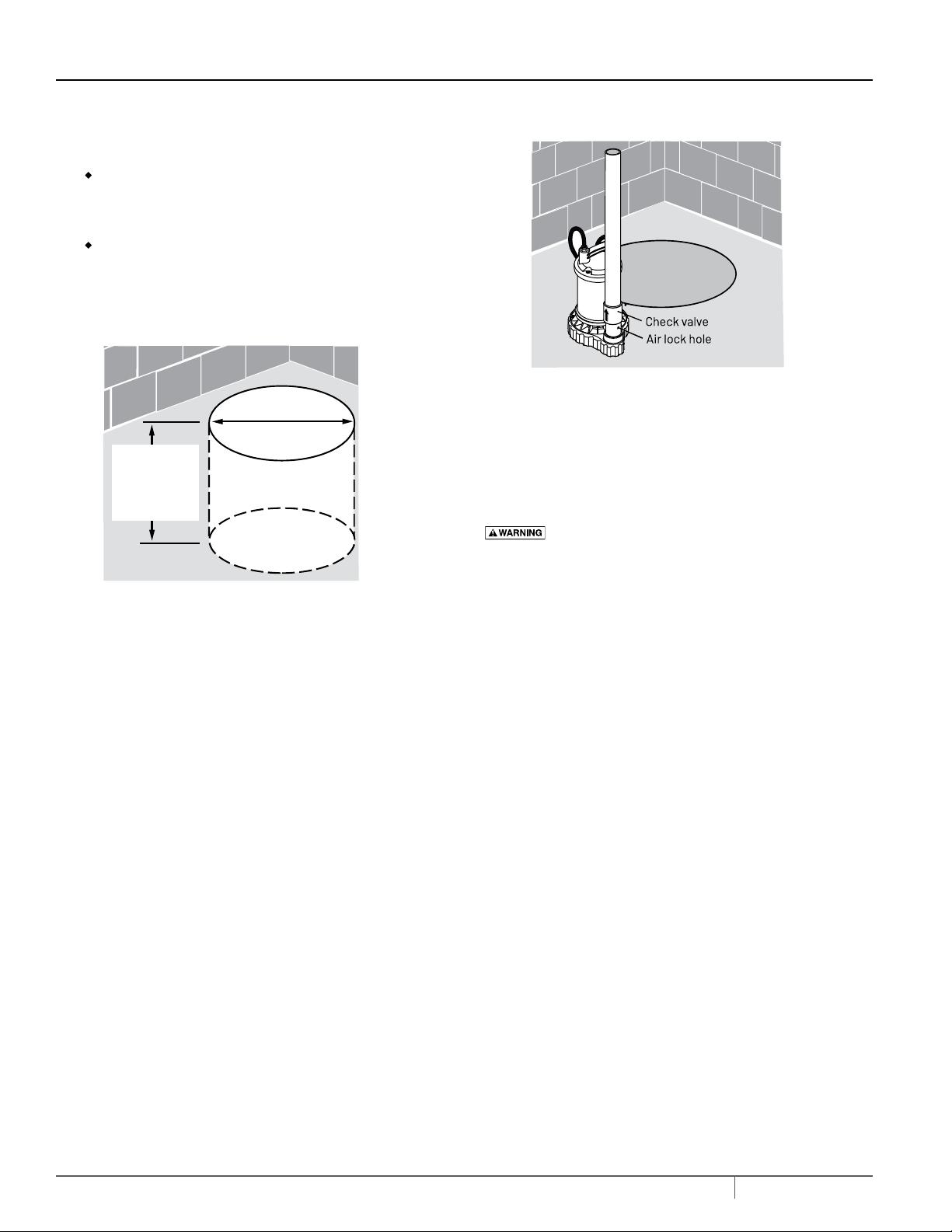
6. Install an in-line check valve or an in-pump check valve to
prevent flow backwards through pump when pump shuts off.
NOTE: If check valve is not equipped with an air bleed hole to
prevent airlocking pump, drill a 1/8” (3.2 mm) hole in discharge
pipe just above where the discharge pipe screws into the
pump discharge. Be sure the hole is below the waterline and
the check valve to prevent air locks.
7. Power Supply: Pump is designed for 115 V., 60 Hz., operation and
requires a minimum 15 amp individual branch circuit. Both pump and
switch are supplied with 3-wire cord sets with grounding-type plugs.
Switch plug is inserted directly into outlet and pump plug inserts
into opposite end of switch plug.
Risk of electric shock.
Can shock, burn or kill. Pump
should always be electrically grounded to a suitable electrical
ground such as a grounded water pipe or a properly grounded
metallic raceway, or ground wire system. Do not cut off round
ground pin.
8. If pump discharge line is exposed to outside sub-freezing
atmosphere, portion of line exposed must be installed so any water
remaining in pipe will drain to the outfall by gravity. Failure to do this
can cause water trapped in discharge to freeze which could result in
damage to pump.
9. After piping, check valve and float switch have been installed, the
unit is ready for operation.
10. Secure power cords to the discharge pipe so they are out of the way
for proper float switch operation, prior to testing the unit.
INSTALLATION
Sump Pit
Hard Surface –
No Sand, Clay,
Gravel
10” Minimum
with Vertical Switch
13” Min. with
Vertical Switch
Figure 1 - Sump Pit
Figure 2 - Air Lock Hole
5
MY1016-R (06-23-20)
11. Check the pump operation by filling sump with water and
observing pump operation through one complete cycle. For switch
settings see the Electrical and Switch Specifications chart in this
manual.
Risk of flooding.
Can cause personal injury and/or
property damage. Failure to make this operational check may lead
to improper operation, premature failure, and flooding.
OPERATION
1. Shaft seal depends on water for lubrication. Do not operate pump
unless it is submerged in water as seal may be damaged if allowed
to run dry.
Risk of electric shock. Can shock, burn or kill. Do not
handle a pump or pump motor with wet hands or when standing on
wet or damp surface, or in water.
2. Motor is equipped with automatic reset thermal protector. If
temperature in motor should rise excessively, switch will cut off all
power before damage can be done to motor. When motor has cooled
sufficiently, switch will reset automatically and restart motor. If
protector trips repeatedly, pump should be removed and checked
as to cause of difficulty. Low voltage, long extension cords, clogged
impeller, very low head or lift, or a plugged or frozen discharge pipe,
etc., could cause cycling.
3. Pump will not remove all water. If operating a pump manually, and
suddenly no water comes out of the discharge hose, shut off the
unit immediately. The water level is probably very low and the unit
has broken prime.
Risk of electric shock. Can shock, burn or kill. Before
attempting to check why unit has stopped operating, disconnect
power from unit.
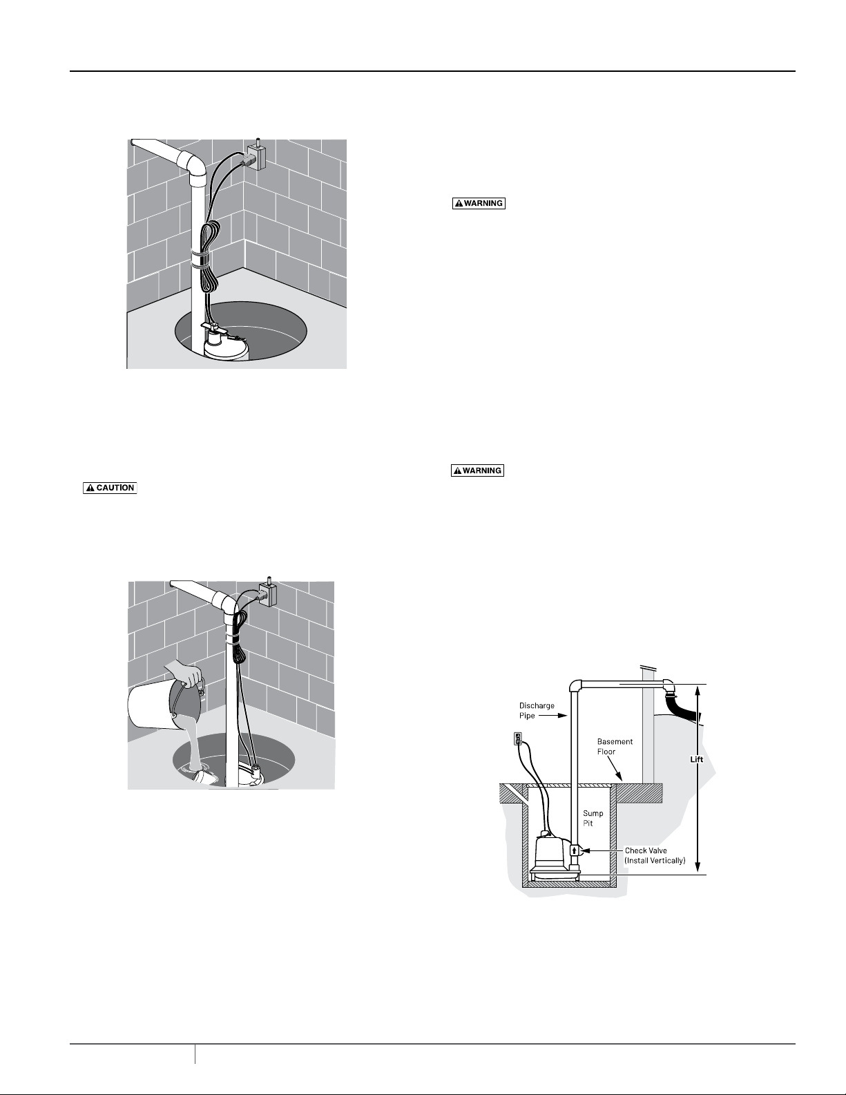
Lift is the vertical distance the pump actually lifts water. The higher
the lift, the lower the flow.
The friction caused by water running through the pipe will also,
on longer pipe runs, reduce the flow. Pipe smaller than the pump
discharge also reduces flow.
INSTALLATION/OPERATION
Figure 3 - Secure Power Cords
Figure 4 - Check Pump
Figure 5 - Lift