pentair.com
MY1000-R (06-22-20) ©2020. All Rights Reserved.
INSTALLATION AND
OPERATION MANUAL
SUBMERSIBLE PLASTIC SUMP PUMP
MSP33T10-R
ENGLISH: 1-9
FRANCAIS: 10-18
ESPANOL: 19-27

2
MY1000-R (06-22-20)
TABLE OF CONTENTS
SECTION ................................................................................................................................................................................................ PAGE
Safety Information ................................................................................................................................................................................ 3
Installation ........................................................................................................................................................................................... 4
Performance & Specications .............................................................................................................................................................. 6
Parts List .............................................................................................................................................................................................. 7
Troubleshooting .................................................................................................................................................................................... 8
Warranty ............................................................................................................................................................................................... 9
3
MY1000-R (06-22-20)
SAVE THESE INSTRUCTIONS: This manual contains important
instructions that should be followed during installation,
operation, and maintenance of the product.
SAFETY SYMBOLS
This is the safety alert symbol. When you see this symbol
on your pump or in this manual, look for one of the following
signal words and be alert to the potential for personal injury:
warns about hazards that will cause serious
personal injury, death or major property damage if ignored.
warns about hazards that can cause serious
personal injury, death or major property damage if ignored.
warns about hazards that will or can cause
minor personal injury or property damage if ignored.
The word NOTE indicates special instructions that are
important but not related to hazards.
PACKAGING INSPECTION
When the unit is received, look for any product damage as you
unpack the item. If any damage is present or parts are missing,
do not attempt to operate pump. Use this manual to determine
that all parts are properly installed. If you are in doubt, do not
operate the pump.
Before you start first, refer to local codes to ensure safety
and regulatory compliance. This sump pump should give years
of trouble-free service when correctly installed, maintained,
and used. However, interruption of power to the pump,
dirt/debris in the sump, flooding that exceeds the pump’s
capacity, electrical or mechanical failure in the pump, etc.,
may prevent normal pump operation. To help prevent damage
from flooding, purchase a secondary AC sump pump, a DC
backup sump pump, and/or a high water alarm.
CALIFORNIA PROPOSITION 65 WARNING:
This product and related accessories contain
chemicals known to the State of California to cause cancer,
birth defects or other reproductive harm.
GENERAL SAFETY
Carefully read and follow all safety instructions in this
manual and on the unit itself. Failure to comply with the
safety instructions could result in personal injury and/or
property damage!
Know the pump application, limitations, and potential
hazards.
Follow all applicable local and state codes and
regulations.
This pump is designed for use in a residential sump only.
Only pump water with this pump. This unit is not designed
as a waterfall, ponds, or fountain pump, or for applications
involving salt water or brine! Not designed for use in a
swimming pool. Do not use where water recirculates.Use
with these will void warranty.
Do not use in water with fish present. If any oil leaks out of the
motor it can kill fish.
Keep safety labels in good condition, replacing any
missing or damaged labels.
Disconnect power before servicing.
Drain all water from system before servicing. Release all
pressure within system before servicing any component.
Secure discharge line before starting pump. An unsecured
discharge line will whip, possibly causing personal injury
and/or property damage.
Check hoses for weak or worn condition before each use,
making certain that all connections are secure.
Periodically inspect sump, pump and system components.
Keep free of debris and foreign objects.
Provide means of pressure relief for pumps whose discharge
line can be shut-off or obstructed.
Do not touch an operating motor. Modern motors can operate
at high temperatures.
Do not handle pump or pump motor with wet hands or when
standing on wet or damp surface, or in water.
Personal Safety:
a. Wear safety glasses at all times when working with
pumps.
b. Keep work area clean, uncluttered and properly
lighted – replace all unused tools and equipment.
c. Keep visitors at a safe distance from work area.
d. Make workshop child-proof – with padlocks, master
switches, and by removing starter keys.
ELECTRICAL SAFETY
Hazardous voltage. Can shock, burn, or kill.
When installing, operating, or servicing this pump, follow the
safety instructions listed below.
DO NOT allow the plug on the end of the electrical cord to
be submerged.
This equipment is only for use on 115 volt (single phase) and is
equipped with an approved 3-conductor cord and 3-prong,
grounding-type plug.
Where a 2-prong wall receptacle is encountered, it must be
replaced with properly grounded 3-prong receptacle installed
in accordance with codes and ordinances that apply.
All wiring should be performed by a qualified electrician.
Make certain power source conforms to requirements of your
equipment.
Protect electrical cord from sharp objects, hot surfaces, oil,
and chemicals. Avoid kinking cord. Replace or repair damaged
or worn cords immediately.
Do not lift pump by cord.
SAFETY INFORMATION
4
MY1000-R (06-22-20)
INSTALLATION
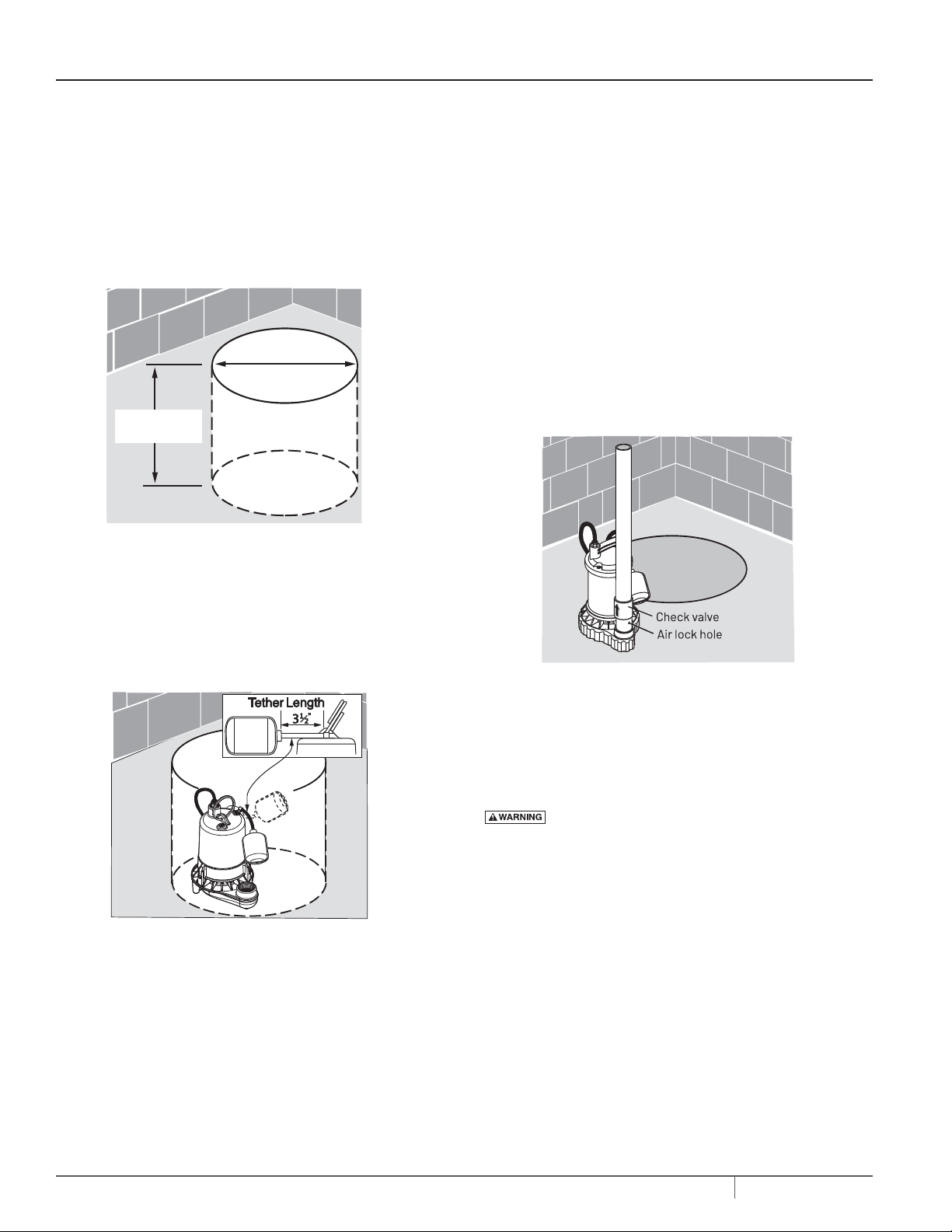
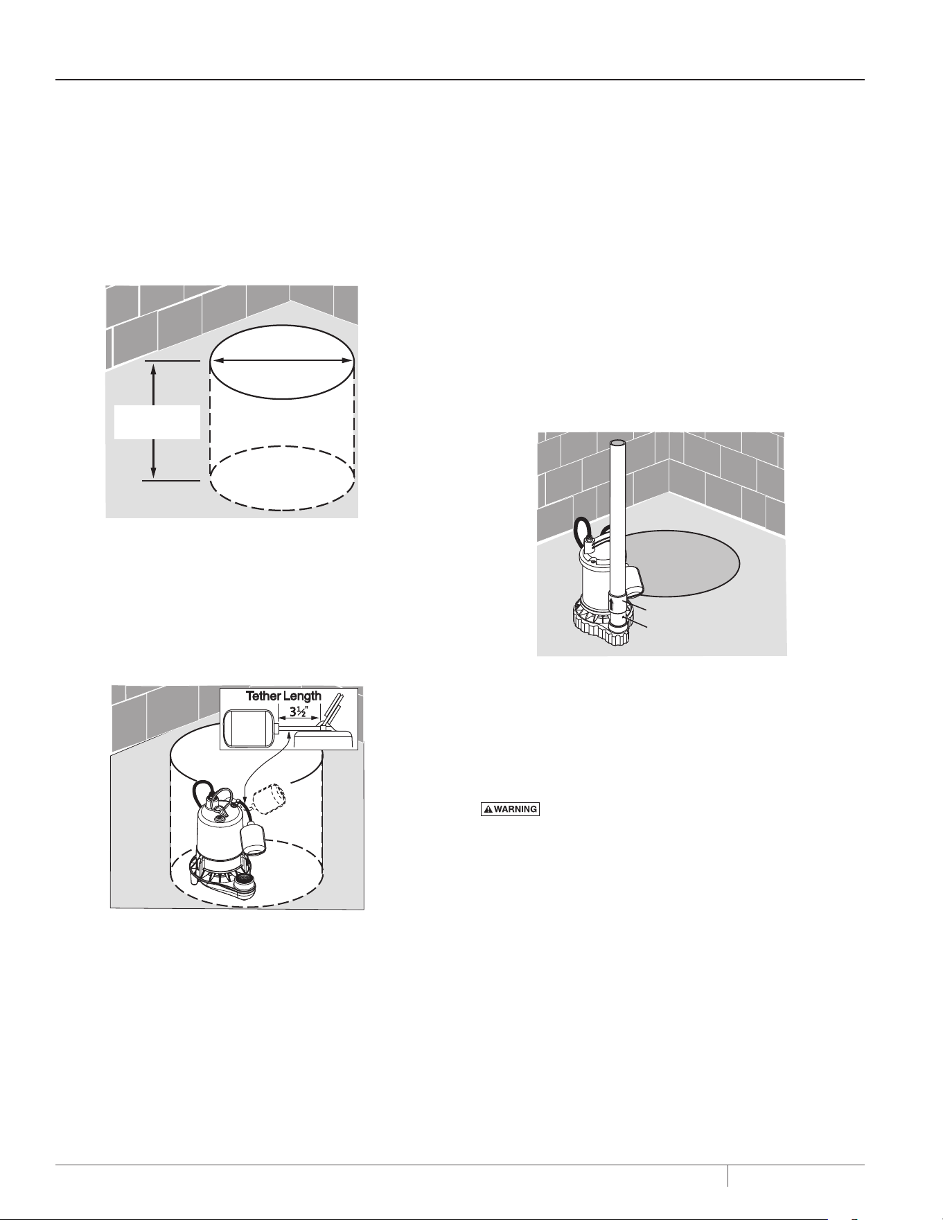
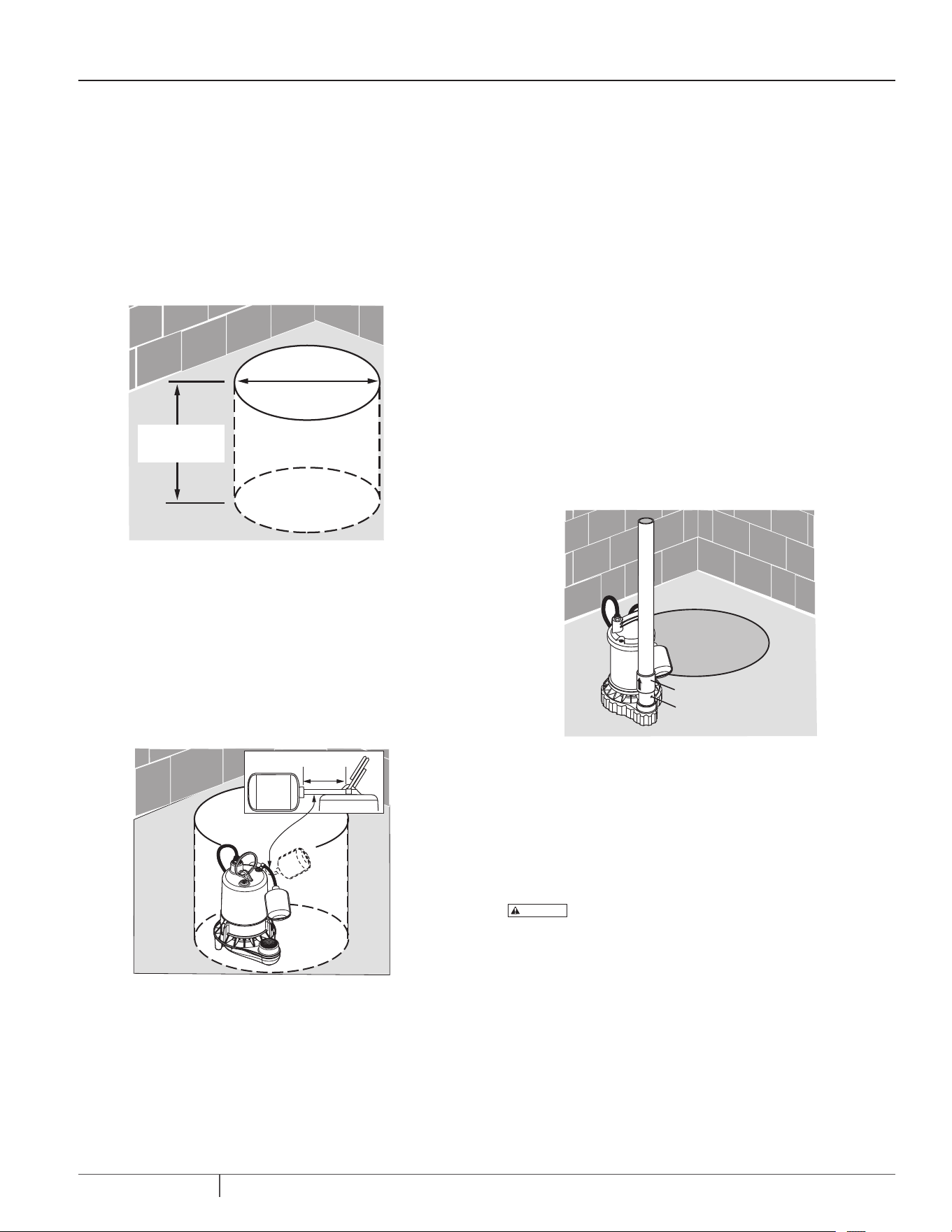
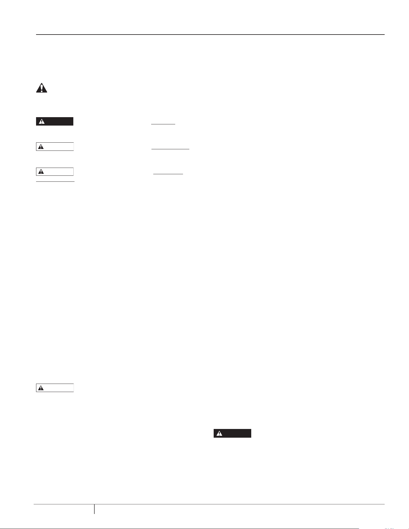
1. Install pump in sump pit with minimum diameter of
14”
(356mm).
Sump depth should be
18” (457mm).
Construct sump pit of tile, concrete, steel or plastic.
Check local codes for approved materials and for proper
installation.
2. Install pump in pit so that switch operating mechanism has
maximum possible clearance.
3. Pump should not be installed on clay, earth or sand surfaces.
Clean sump pit of small stones and gravel which could clog
pump. Keep pump inlet screen clear.
4. Install discharge plumbing. Use rigid plastic pipe and wrap
threads with
PTFE pipe thread sealant tape
. Screw pipe into
pump hand tight plus 1-1/2 turns. Do not use ordinary pipe joint
compound on plastic pipe as it can attack plastics.
If a flexible discharge hose is used, make sure pump is secured
in sump to prevent movement. Failure to secure pump may allow
pump movement, switch interference and prevent pump from
starting or stopping.
5. To reduce motor noise and vibrations, a short length of rubber
hose (1-7/8” (47.6mm) I.D., e.g. radiator hose) can be connected into
discharge line near pump using suitable clamps.
6. Install an in-line check valve or an in-pump check valve to prevent
flow backwards through pump when pump shuts off.
NOTE: If check valve is not equipped with an air bleed hole to
prevent airlocking pump, drill a 1/8” (3.2 mm) hole in discharge
pipe just above where the discharge pipe screws into the pump
discharge. Be sure the hole is below the waterline and the check
valve to prevent air locks.
7. Power Supply: Pump is designed for 115 V., 60 Hz., operation and
requires a minimum 15 amp individual branch circuit. Both pump and
switch are supplied with 3-wire cord sets with grounding-type plugs.
Switch plug is inserted directly into outlet and pump plug inserts
into opposite end of switch plug.
Risk of electric shock. Can shock, burn or kill. Pump
should always be electrically grounded to a suitable electrical
ground such as a grounded water pipe or a properly grounded
metallic raceway, or ground wire system. Do not cut off round
ground pin.
8. If pump discharge line is exposed to outside sub-freezing
atmosphere, portion of line exposed must be installed so any water
remaining in pipe will drain to the outfall by gravity. Failure to do this
can cause water trapped in discharge to freeze which could result in
damage to pump.
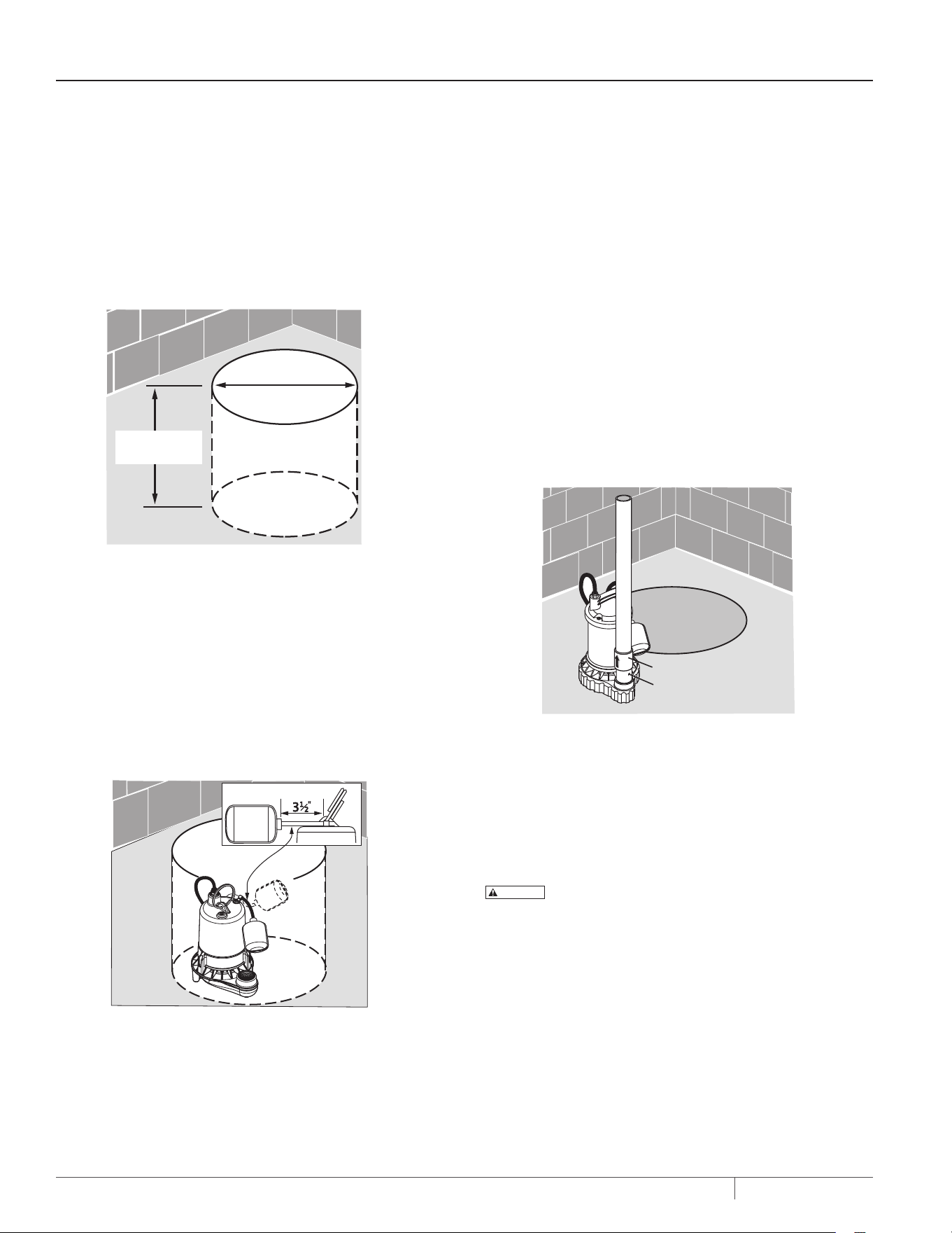
9. After piping, check valve and float switch have been installed, the
unit is ready for operation.
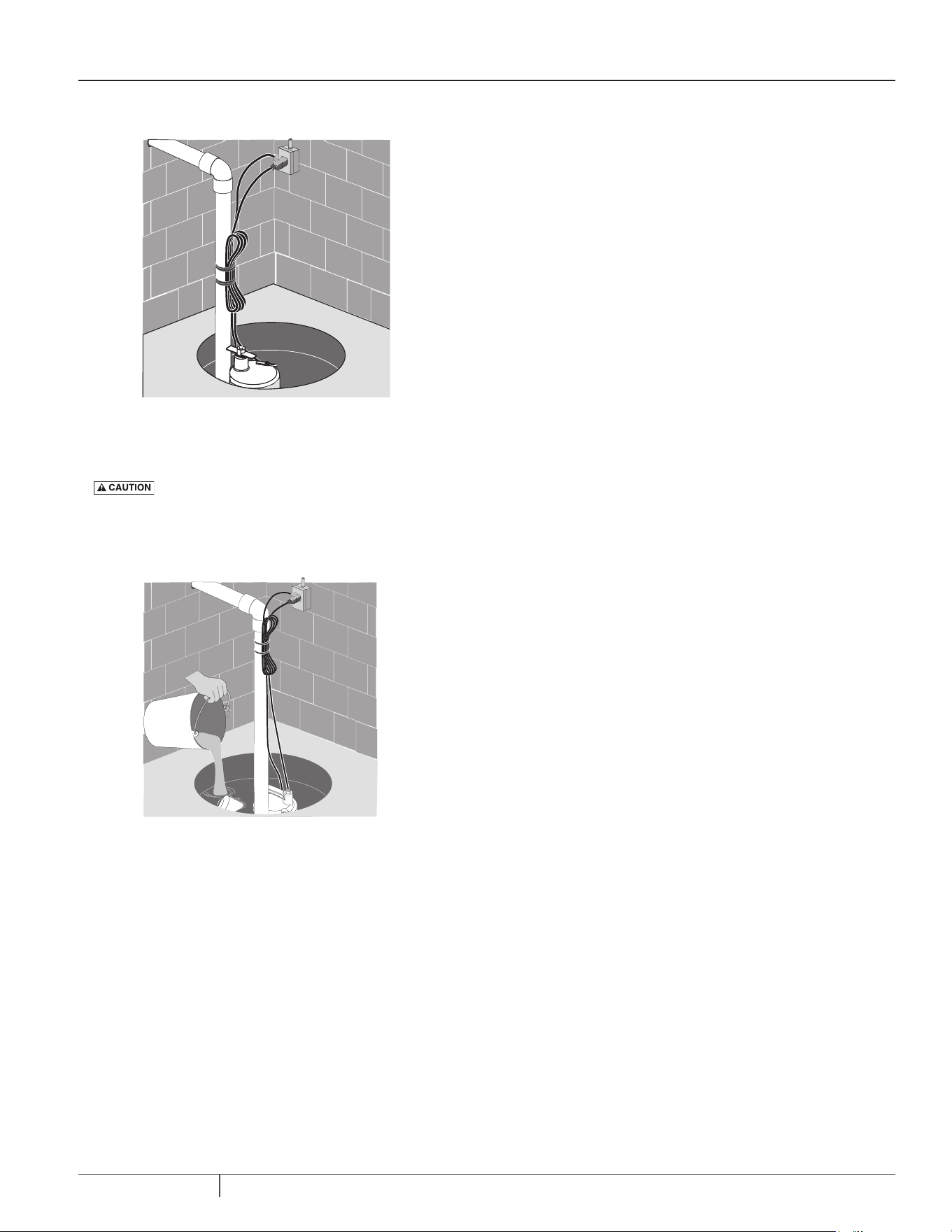
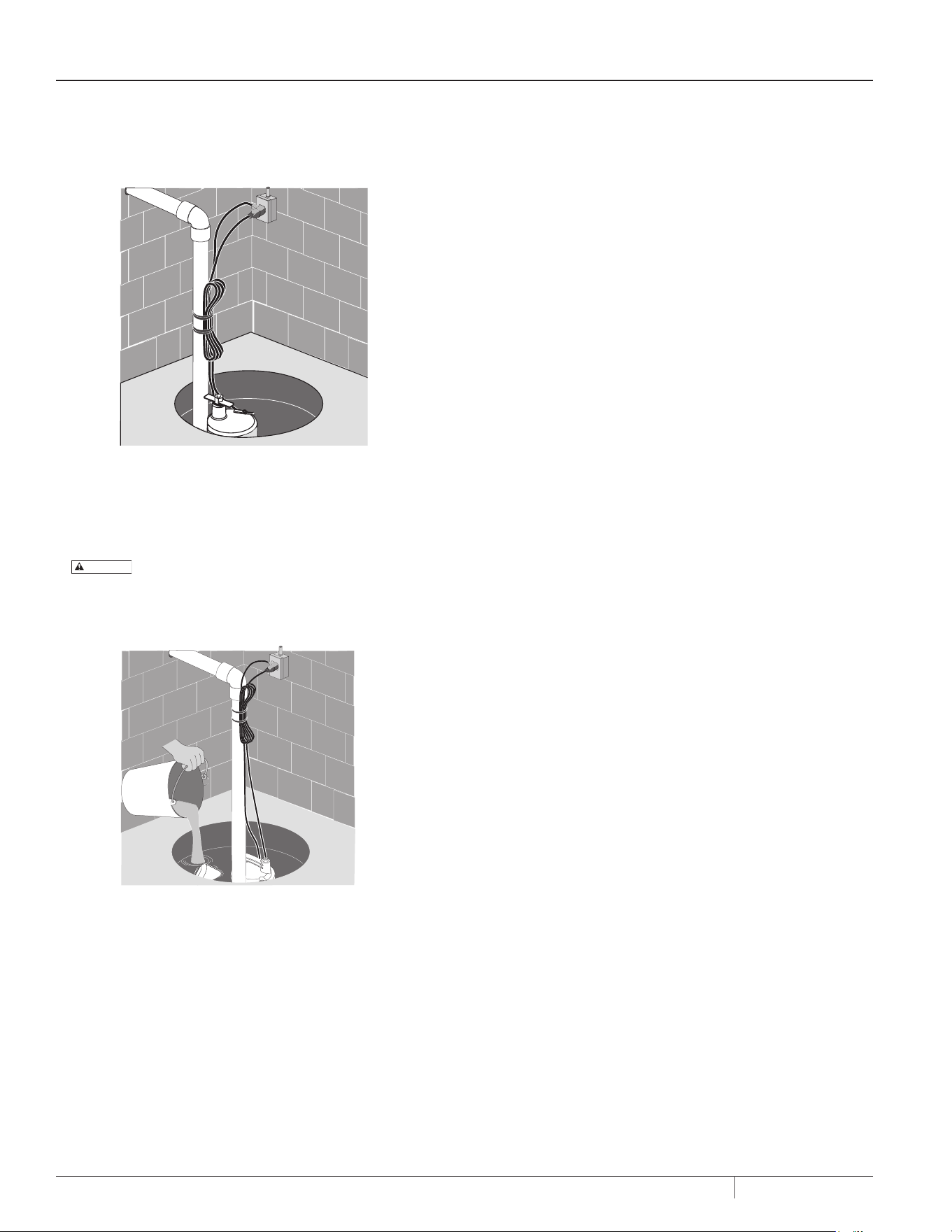
10. Secure power cords to the discharge pipe so they are out of the way
for proper float switch operation, prior to testing the unit.
INSTALLATION
4824 1216
Sump Pit
Hard Surface –
No Sand, Clay,
Gravel
14” Minimum
with Tethered Switch
18” Min. with
Tethered Switch
Figure 1 - Sump Pit
Figure 2 - Pump Placement
Check valve
Air lock hole
Figure 3 - Air Lock Hole
6202 04106202 0410
6201 04106201 041 0
5
MY1000-R (06-22-20)
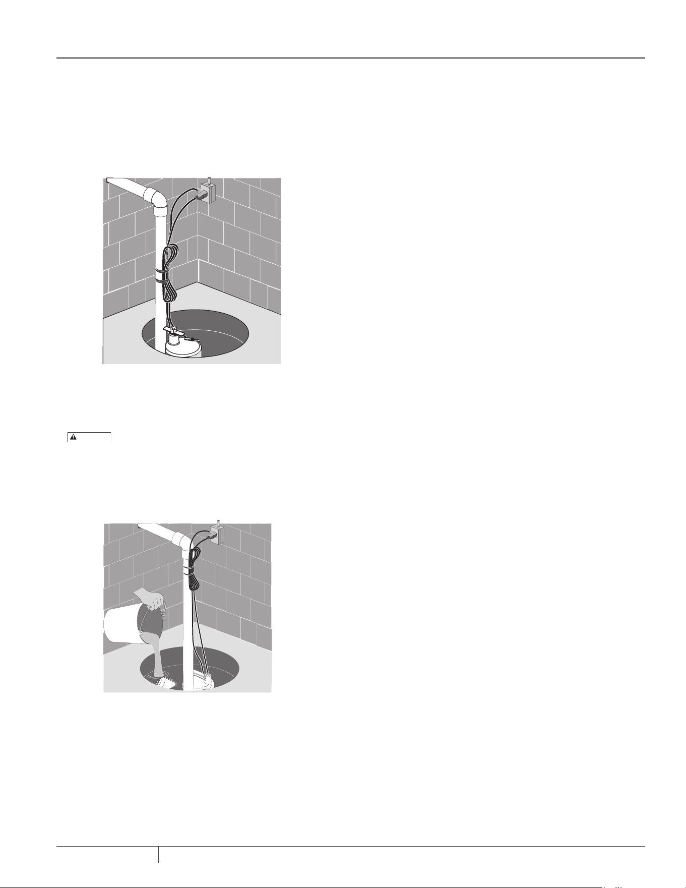
11. Check the pump operation by filling sump with water and
observing pump operation through one complete cycle.
Risk of flooding. Can cause personal injury and/or
property damage. Failure to make this operational check may lead
to improper operation, premature failure, and flooding.
INSTALLATION
6615 0415
4829 0205
Figure 4 - Secure Power Cords
Figure 5 - Check Pump

6
MY1000-R (06-22-20)
PERFORMANCE & SPECIFICATIONS
SPECIFICATIONS
Power supply required..............................................................................................................................115V, 60 HZ.
Liquid temp. range...................................................................................................................................32°F to 70°F(0°-21°C)
Individual branch circuit required (min.)...................................................................................................15 Amps
Discharge.................................................................................................................................................1-1/2” NPT
NOTE:
Do not reduce size of discharge pipe or hose below 1-1/4” diameter. If discharge is too small, pump will overheat and fail prematurely.
ELECTRICAL & SWITCH SPECIFICATIONS
SERIES HP
MOTOR FULL
LOAD AMPS
INDIVIDUAL
BRANCH CIRCUIT
REQ. (AMPS)
AUTOMATIC SWITCH
TYPE
SWITCH SETTING IN INCHES
WATER LEVEL FOR:
ON OFF
MSP33T10-R 1/3 3.9 15.0 AMP 115V Piggyback Tethered 14" 5"
PERFORMANCE
GPH (LPH) at total feet (m) of lift
SERIES HP
0
(0.0m)
5
(1.5m)
10
(3m)
15
(4.6M)
20
(6.1M)
NO FLOW AT
HEIGHT SHOWN
BELOW IN FEET
(METERS)
Capacity Gallons(L)/Hour
MSP33T10-R 1/3
3600
(13627)
3180
(12038)
2700
(10221)
2160
(8176)
1440
(5451)
24
(7.3)
7
MY1000-R (06-22-20)
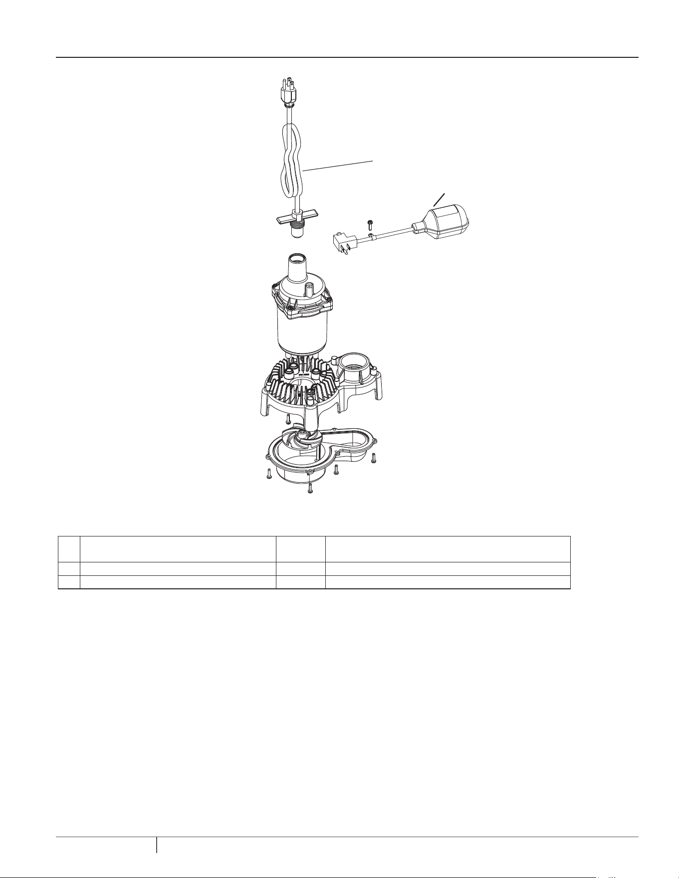
PARTS LIST
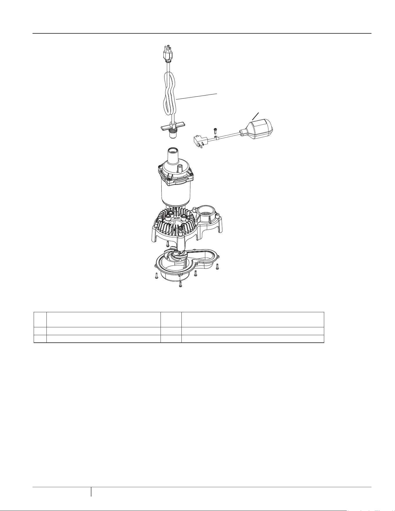
Figure 6 - MSP33T10-R
1
2
Ref Description Qty MSP33T10-R
1 Power Cord Assembly 1 PS117-2119
2 Tethered Float Switch Assembly 1 FP18-15BD-P2

8
MY1000-R (06-22-20)
TROUBLESHOOTING
SYMPTOM POSSIBLE CAUSE CORRECTIVE ACTION
Pump won't start.
Pump not plugged in Check that pump is plugged into a proper outlet.
Blown fuse If blown, replace with fuse of proper size.
Low line voltage
If voltage is under recommended minimum, check size of
wiring from main switch on property. If OK, contact power
company or hydro authority.
Defective motor Replace pump.
Defective float switch Replace float switch.
Impeller
If impeller won't turn, remove lower pump body and locate
source of binding.
Float obstructed Remove obstruction.
Pump starts and stops frequently.
Backflow of water from piping Install or replace check valve.
Faulty float switch Replace float switch.
Pump won’t shut off
Defective float switch Replace float switch.
Restricted discharge (obstacle or ice in piping) Remove pump and clean pump and piping.
Float obstructed Remove obstruction.
Restricted intake screen Remove the pump and clean the intake screen and the impeller.
Pump operates but delivers little or
no water.
Low line voltage
If voltage under recommended minimum, check size of wiring from
main switch on property. If OK, contact power company or hydro
authority.
Something caught in impeller Remove the pump and clean out the impeller.
Worn or defective parts or plugged impeller Clean impeller if plugged; otherwise replace pump.
Check valve installed without vent hole
Drill a 1/16” - 1/8” (1.6mm-3.2mm) dia. hole between pump discharge
& check valve (1-2” above where the discharge pipe screws into the
pump discharge and below the waterline).
Restricted intake screen Remove the pump and clean out the intake screen.
Check valve is installed either backward or upside
down
Be sure check valve is installed correctly.

9
MY1000-R (06-22-20)
WARRANTY
Limited Warranty
Myers warrants to the original consumer purchaser (“Purchaser” or “You”) of the products listed below, that they will be free from defects in
material and workmanship for the Warranty Period shown below.
SEWAGE PUMPS
DO NOT return a sewage pump (that has been installed) to your retail store. Sewage pumps that have seen service and been removed carry a
contamination hazard with them. If your sewage pump has failed:
Wear rubber gloves when handling the pump.
For warranty purposes, return the pump’s cord tag and original receipt of purchase to the retail store.
Dispose of the pump according to local disposal ordinances.
Contact Pentair Myers Customer Service at 1-888-987-8677.
TWENTY-FOUR (24) MONTH FROM DATE OF PURCHASE LIMITED WARRANTY:
Product Model
Sump MSP33T10-R, MS50V10-R, MSCI50V10-R, MSCI75V10-R, MSZ100V10-R
Effluent ME40T20-R
Sewage MSW50T10-R, MSWE5012P10-R, MSWKV75VT20-R, MSW50TBP-R
Utility MUCA25-R
Our warranty applies only where such products are used in compliance with the requirements of the applicable product catalog and/or
manuals. For additional information, please refer to the applicable standard limited warranty featured in the product manual.
Our warranty will not apply to any product that, in our sole judgement, has been subject to negligence, misapplication, improper installation,
failure to install per owner’s manual, unauthorized product modifications, use of non-MYERS original replacement parts, accidental
damage, fire, acts of God, other circumstances outside of our control, or improper maintenance. Note that this limited warranty applies to
manufacturing defects only and not to ordinary wear and tear. All mechanical devices need periodic parts and service to perform well. This
limited warranty does not cover repair when normal use has exhausted the life of a part or the equipment. Without limiting the foregoing,
operating a three phase motor with single phase power through a phase converter will void the warranty. Note also that three phase motors
must be protected by three-leg, ambient compensated, extra-quick trip overload relays of the recommended size or the warranty is void.
The original purchase receipt and product warranty information label are required to determine warranty eligibility. Eligibility is based on
purchase date of original product – not the date of replacement under warranty. Your only remedy for proven defect covered by this warranty,
and MYERS’s only duty, is that MYERS repair or replace defective products (at MYERS’s sole choice). You must pay all labor and shipping charges
associated with this warranty and must request warranty service through the installing dealer as soon as a problem is discovered. No request
for service will be accepted if received after the Warranty Period has expired. This warranty is not transferable.
MYERS SHALL NOT BE LIABLE FOR ANY CONSEQUENTIAL, INCIDENTAL, OR CONTINGENT DAMAGES WHATSOEVER.
THE FOREGOING LIMITED WARRANTIES ARE EXCLUSIVE AND IN LIEU OF ALL OTHER EXPRESS AND IMPLIED WARRANTIES, INCLUDING
BUT NOT LIMITED TO IMPLIED WARRANTIES OF MERCHANTABILITY AND FITNESS FOR A PARTICULAR PURPOSE. THE FOREGOING LIMITED
WARRANTIES SHALL NOT EXTEND BEYOND THE DURATION PROVIDED HEREIN.
Some states do not allow the exclusion or limitation of incidental or consequential damages or limitations on the duration of an implied
warranty, so the above limitations or exclusions may not apply to You. This warranty gives You specific legal rights and You may also have other
rights which vary from state to state.
No dealer or other person has any authority to make any different warranties or representations concerning Pentair or Pentair products.
Accordingly, Pentair nor any of its entities are to be held responsible for any such warranties or representation.
This Limited Warranty is effective October 1, 2020 and replaces all undated warranties and warranties dated before October 1, 2020.
F.E. MYERS
293 Wright Street, Delavan, WI 53115
Phone: 888-987-8677 • Fax: 800-426-9446 • PENTAIR.COM/MYERS
In Canada: 490 Pinebush Road, Unit 4, Cambridge, Ontario N1T 0A5
Phone: 800-363-7867 • Fax: 888-606-5484
pentair.com
MY1000-R (22-06-20) ©2020. Tous droits réservés.
MANUEL D’INSTALLATION
ET D’UTILISATION
POMPE DE PUISARD SUBMERSIBLE
EN PLASTIQUE
MSP33T10-R

11
MY1000-R (06-22-20)
TABLE DES MATIÈRES
SECTION ................................................................................................................................................................................................ PAGE
Renseignements relatifs à la sécurité .................................................................................................................................................. 12
Installation ..........................................................................................................................................................................................13
Performance et spécications ............................................................................................................................................................ 15
Liste des pièces ................................................................................................................................................................................... 16
Dépannage ...........................................................................................................................................................................................17
Garantie ............................................................................................................................................................................................... 18
12
MY1000-R (06-22-20)
CONSERVEZ CES INSTRUCTIONS: Ce manuel contient des consignes
importantes qui doivent être suivies pendant l’installation, l’utilisation et
l’entretien du produit.
SYMBOLES DE SÉCURITÉ
Ceci est le symbole d’alerte de sécurité. Si vous voyez ce
symbole sur votre pompe ou dans ce manuel, cherchez l’un des
mots d’avertissement ci-dessous et soyez attentif aux risques
de blessures corporelles:
signale un danger qui provoquera la mort, des
blessures corporelles graves ou des dommages matériels
importants s’il est ignoré.
MISE EN GARDE
signale un danger qui peut provoquer la mort,
des blessures corporelles graves ou des dommages matériels
importants s’il est ignoré.
ATTENTION
signale un danger qui provoquera ou peut
provoquer des lésions corporelles légères ou des dommages
matériels s’il est ignoré.
Le mot REMARQUE indique des consignes spéciales non liées
aux dangers.
INSPECTION DE L’EMBALLAGE
Lorsque vous recevez l’appareil, portez attention aux
dommages possibles quand vous le déballez. En cas de
dommage ou de pièces manquantes, n’essayez pas de faire
fonctionner la pompe. Utilisez ce manuel pour vous assurer
que toutes les pièces sont correctement installées. En cas de
doute, n’utilisez pas la pompe.
Avant de commencer, reportez-vous aux codes locaux pour
garantir la sécurité et la conformité réglementaire. Cette
pompe de puisard devrait offrir des années de service sans
problème si elle est correctement installée, entretenue
et utilisée. Cependant, une interruption de l’alimentation
de la pompe, de la saleté ou des débris dans le puisard,
une inondation dépassant la capacité de la pompe, une
panne électrique ou mécanique de la pompe, etc., peuvent
compromettre le fonctionnement normal de la pompe. Pour
éviter les dommages causés par les inondations, achetez une
pompe de puisard CA secondaire, une pompe depuisard CC de
secours ou une alarme de niveau d’eau élevé.
AVERTISSEMENT CONCERNANT LA CALIFORNIA PROPOSITION 65
MISE EN GARDE
Ce produit et les accessoires connexes
contiennent des produits chimiques considérés par l’État
de la Californie comme pouvant causer le cancer, des
anomalies congénitales ou d’autres problèmes liés au système
reproducteur.
SÉCURITÉ GÉNÉRALE
Lisez attentivement et suivez toutes les instructions
de sécurité se trouvant dans le présent guide et sur
l’unité elle-même. Le non-respect des consignes de
sécurité peut entraîner des blessures corporelles ou des
dommages matériels.
Renseignez-vous sur l’utilisation, les limites et les
dangers potentiels de la pompe. Suivez tous les codes et
règlements locaux et nationaux applicables.
Cette pompe est conçue pour être utilisée dans un
puisard résidentiel uniquement. Utilisez cette pompe
uniquement pour pomper de l’eau. Cet appareil n’est pas
conçu comme une pompe de cascade, de bassin ou de
fontaine, ou pour être utilisé avec de l’eau salée ou de la
saumure! La pompe n’est pas conçue pour être utilisée
dans une piscine. Ne pas utiliser là où l’eau recircule. Une
telle utilisation aura pour effet d’annuler la garantie.
Ne pas utiliser dans l’eau avec la présence de poissons. Si
de l’huile s’échappe du moteur, elle peut tuer les poissons.
Conservez les étiquettes de sécurité en bon
état; remplacez-les si elles sont manquantes ou
endommagées.
Débranchez l’alimentation électrique avant de procéder à
l’entretien.
Vidangez toute l’eau du système avant de procéder à
l’entretien. Relâchez toute la pression dans le système
avant d’entretenir un composant.
Fixez la conduite d’évacuation avant de démarrer la
pompe. Une conduite d’évacuation non sécurisée
pourrait créer un effet de fouet et causer des blessures
corporelles ou des dommages matériels.
Vérifiez si les tuyaux sont en bon état et non usés avant
chaque utilisation, en vous assurant que toutes les
connexions sont sécurisées.
Inspectez périodiquement les composants du puisard, de
la pompe et du système. Gardez les débris et les objets
étrangers à l’écart.
Assurez un moyen de décompression pour les pompes dont
la conduite d’évacuation peut être fermée ou obstruée.
Ne touchez pas à un moteur en marche. Les moteurs
modernes peuvent fonctionner à des températures élevées.
Ne manipulez pas la pompe ou le moteur de la pompe avec
les mains mouillées ou lorsque vous vous trouvez sur une
surface mouillée ou humide, ou dans l’eau.
Sécurité personnelle:
a. Portez des lunettes de sécurité en tout temps lorsque vous
travaillez avec des pompes.
b. Gardez la zone de travail propre, dégagée et correctement
éclairée. Rangez tous les outils et équipements inutilisés.
c. Gardez les visiteurs à une distance sécuritaire de la zone de travail.
d. Rendez l’atelier sécuritaire pour les enfants – avec des cadenas,
des commutateurs principaux et en retirant les clés de démarrage.
SÉCURITÉ ÉLECTRIQUE
Tension dangereuse. Peut causer un choc
électrique, des brûlures ou la mort. Suivez les instructions
de sécurité indiquées ci-dessous durant l’installation, le
fonctionnement ou l’entretien de la pompe.
CONSIGNES DE SÉCURITÉ
13
MY1000-R (06-22-20)
INSTALLATION
1. Installez la pompe dans un puisard ayant un diamètre
minimal de 14po (356mm).
La profondeur du puisard doit être de 18po (457mm).
Construisez un puisard en tuiles, en béton, en acier ou
en plastique. Consultez les codes locaux pour connaître
les matériaux approuvés etles exigences d’installation
adéquate.
2. Installez la pompe dans la fosse de manière à assurer un
dégagement maximal autour du mécanisme de commande
de l’interrupteur.
3. La pompe ne doit pas être installée sur une surface d’argile,
de terre ou de sable. Retirez du puisard les petites pierres
et le gravier qui pourraient obstruer la pompe. Gardez la
grille d’entrée de la pompe dégagée.
4. Installez la plomberie d’évacuation. Utilisez un tuyau en plastique rigide
et enveloppez les filets avec un ruban d’étanchéité pour filetage de
tuyau en PTFE. Vissez à la main le tuyau dans la pompe et faites un tour
et demi de plus. N’utilisez pas de composé à joint de tuyau ordinaire sur
un tuyau en plastique, car il peut endommager les plastiques.
Si vous utilisez un tuyau d’évacuation flexible, assurez-vous que la
pompe est fixée dans le puisard pour empêcher tout mouvement. Le fait
de ne pas fixer la pompe peut entraîner le mouvement de la pompe, des
interférences avec l’interrupteur et empêcher la pompe de démarrer oude
s’arrêter.
5. Pour réduire le bruit et les vibrations du moteur, il est possible de raccorder
un court tuyau en caoutchouc de 17/8po ou 47,6mm (comme un tuyau pour
radiateur) à la conduite d’évacuation près de la pompe à l’aide d’une pince.
6. Installez un clapet de non-retour en ligne ou un clapet de non-retour dans
la pompe pour empêcher une inversion de flux dans la pompe lorsqu’elle
s’arrête.
REMARQUE: Si le clapet de non-retour n’est pas équipé d’un
trou de purge d’air pour éviter le blocage par l’air de la pompe,
percez un trou de 1/8po (3,2mm) dans le tuyau d’évacuation
juste au-dessus de l’endroit où le tuyau d’évacuation se visse
dans le refoulement de la pompe. Assurez-vous que le trou se
trouve sous la ligne d’eau et le clapet de non-retour pour éviter
les bouchons d’air.
7. Bloc d’alimentation: La pompe est conçue pour un fonctionnement à
115V et 60Hz, et nécessite un circuit de dérivation individuel minimum de
15ampères. La pompe et l’interrupteur comprennent des jeux de câbles à
3fils avec des fiches de mise à la terre. La fiche de l’interrupteur est insérée
directement dans la prise et la fiche de la pompe s’insère dans l’extrémité
opposée de la fiche de l’interrupteur.
MISE EN GARDE
Risque de décharge électrique. Peut causer une décharge
électrique, des brûlures ou la mort. La pompe doit toujours être mise à la
terre sur une mise à la terre électrique appropriée, telle qu’une conduite
d’eau mise à la terre ou un conduit métallique correctement mis à la terre,
ou un réseau de prises de terre. Ne coupez pas la broche de terre ronde.
8. Si la conduite d’évacuation de la pompe est exposée à un climat extérieur
sous le point de congélation, la partie de la conduite exposée doit être
installée de sorte que toute eau restant dans la conduite s’écoule vers
l’exutoire par gravité. Autrement, l’eau emprisonnée dans la conduite
d’évacuation peut geler, ce qui pourrait endommager la pompe.
9. Après l’installation de la tuyauterie, du clapet de non-retour et de
l’interrupteur à flotteur, l’appareil est prêt à fonctionner.
INSTALLATION
4824 1216
Puisard
Surface dure:
pas de sable,
d’argile ou de gravier
14po minimum avec
interrupteur attaché
18 po minimum
avec interrupteur
attaché
Figure1 – Puisard
Figure2 – Positionnement de la pompe
Clapet de non-retour
Trou de poche d’air
Figure3 – Trou de poche d’air
6202 041 0
6202 0410
6201 041 0
6201 0410
Longueur d’attache:
31/2po
14
MY1000-R (06-22-20)
10. Avant de tester l’appareil, fixez les cordons d’alimentation au tuyau
d’évacuation afin qu’ils ne gênent pas le bon fonctionnement de
l’interrupteur à flotteur.
11. Vérifiez le fonctionnement de la pompe en remplissant le puisard d’eau et
en observant le fonctionnement de la pompe pendant un cycle complet.
ATTENTION
Risque d’inondation. Peut causer des blessures corporelles
ou des dommages matériels. L’omission de procéder à cette vérification
pourrait entraîner un mauvais fonctionnement, une panne prématurée et
une inondation.
INSTALLATION
6615 0415
4829 0205
Figure4 – Fixation des cordons d’alimenta-
Figure5 – Vérification de la

15
MY1000-R (06-22-20)
PERFORMANCE ET SPÉCIFICATIONS
SPÉCIFICATIONS
Bloc d’alimentation requis ..............................................................................................................................................115V, 60Hz
Plage de température du liquide .....................................................................................................................................32°F à 70°F (0°C à 21°C)
Circuit de dérivation individuel requis (min.) ...................................................................................................................15ampères
Refoulement ..................................................................................................................................................................11/2po NPT
REMARQUE:
Ne réduisez pas la taille du boyau ou du tuyau d’évacuation en dessous de 11/4 po de diamètre. Si le refoulement est trop faible, la pompe
surchauffera et cessera de fonctionner prématurément.
SPÉCIFICATIONS ÉLECTRIQUES ET D’INTERRUPTEURS
SÉRIE HP
INTENSITÉ
MAXIMALE DU
MOTEUR
CIRCUIT DE
DÉRIVATION
INDIVIDUEL
REQUIS (A)
TYPE
D’INTERRUPTEUR
AUTOMATIQUE
RÉGLAGE DE L’INTERRUPTEUR
ENPOUCES NIVEAU D’EAU POUR:
MARCHE ARRÊT
MSP33T10-R 1/3 3,9 15,0A, 115V
À califourchon
attaché
14po 5po
PERFORMANCE
Gal/h (l/h) à un levage maximal en pieds (m)
SÉRIE HP
0
(0m)
5
(1,5m)
10
(3m)
15
(4,6M)
20
(6,1M)
AUCUN DÉBIT À LA
HAUTEUR INDIQUÉE
EN PIEDS (MÈTRES)
Capacité en gallons (l)/heure
MSP33T10-R 1/3
3600
(13627)
3180
(12038)
2700
(10221)
2160
(8176)
1440
(5451)
24
(7,3)

16
MY1000-R (06-22-20)
LISTE DES PIÈCES
Figure6 – MSP33T10-R
1
2
Réf. Description Qté MSP33T10-R
1 Ensemble du cordon d’alimentation 1 PS117-2119
2 Ensemble de l’interrupteur à otteur attaché 1 FP18-15BD-P2

17
MY1000-R (06-22-20)
DÉPANNAGE
SYMPTÔME CAUSE POSSIBLE MESURE CORRECTIVE
La pompe ne démarre pas.
La pompe n’est pas branchée. Vérifiez si la pompe est branchée dans une prise appropriée.
Fusible brûlé. Remplacez le fusible par un fusible de taille appropriée s’il estbrûlé.
Tension de ligne basse
Si la tension est inférieure au minimum recommandé, vérifiez
lataille du câblage du commutateur principal de la propriété. S’ilest
adéquat, contactez votre compagnie d’électricité ouvotre autorité
hydroélectrique.
Moteur défectueux. Remplacez la pompe.
Interrupteur à flotteur défectueux. Remplacez l’interrupteur à flotteur.
Roue
Si la roue ne tourne pas, retirez le corps inférieur de la pompe
etlocalisez la source du grippage.
Flotteur obstrué. Enlevez ce qui obstrue.
La pompe démarre et s’arrête
fréquemment.
Refoulement d’eau de la tuyauterie. Installez ou remplacez le clapet de non-retour.
Interrupteur à flotteur défectueux. Remplacez l’interrupteur à flotteur.
La pompe refuse de s’arrêter.
Interrupteur à flotteur défectueux. Remplacez l’interrupteur à flotteur.
Refoulement restreint (obstacle ou glace dans la
tuyauterie).
Retirez la pompe et nettoyez la pompe et la tuyauterie.
Flotteur obstrué. Enlevez ce qui obstrue.
Grille d’entrée restreinte. Retirez la pompe et nettoyez la grille d’entrée et la roue.
La pompe fonctionne mais pompe
trèspeu ou pas d’eau.
Tension de ligne basse
Si la tension est inférieure au minimum recommandé, vérifiez
lataille du câblage du commutateur principal de la propriété. S’il est
adéquat, contactez votre compagnie d’électricité ou votre autorité
hydroélectrique.
Quelque chose est pris dans la roue. Retirez la pompe et nettoyez la roue.
Pièces usées ou défectueuses ou roue bloquée. Nettoyez la roue si elle est bloquée; sinon, remplacez la pompe.
Clapet de non-retour installé sans trou d’aération.
Percez un trou de 1/16 po à 1/8 po (1,6 mm à 3,2 mm) de diamètre
entre le refoulement de la pompe et le clapet de non-retour (1 à2po
au-dessus de l’endroit où le tuyau d’évacuation se visse dans le
refoulement de la pompe et sous la ligne d’eau).
Grille d’entrée restreinte. Retirez la pompe et nettoyez la grille d’entrée.
Le clapet de non-retour est installé à l’envers. Assurez-vous que le clapet de non-retour est installé correctement.

18
MY1000-R (06-22-20)
GARANTIE
Garantie limitée
Myers garantit à l’acheteur initial («l’acheteur» ou «vous») des produits figurant ci-dessous qu’ils seront exempts de tout défaut de matériel et de fabrication pour la
période de garantie indiquée ci-dessous.
POMPES D’ÉGOUT
NE RETOURNEZ PAS une pompe d’égout (si celle-ci a été installée) à votre magasin de détail. Les pompes d’égout qui ont été en service puis retirées présentent un
risque de contamination. Si votre pompe d’égout est définitivement hors d’usage:
Portez des gants de caoutchouc lorsque vous manipulez la pompe.
À des fins de garantie, retournez l’étiquette du cordon de la pompe ainsi que le reçu d’achat original au magasin de détail.
Mettez la pompe au rebut conformément aux règlements relatifs à l’élimination des déchets de votre région.
Communiquez avec le service à la clientèle de Pentair Myers au 1888987-8677.
GARANTIE LIMITÉE DE VINGT-QUATRE (24)MOIS À PARTIR DE LA DATE D’ACHAT:
Produit Modèle
Puisard MSP33T10-R, MS50V10-R, MSCI50V10-R, MSCI75V10-R, MSZ100V10-R
Eaux résiduaires ME40T20-R
Eaux usées MSW50T10-R, MSWE5012P10-R, MSWKV75VT20-R, MSW50TBP-R
Utilitaire MUCA25-R
Notre garantie s’applique uniquement quand ces produits sont utilisés conformément aux exigences du catalogue ou des manuels des produits concernés. Pour plus
d’informations, consultez la garantie limitée standard applicable dans le manuel du produit.
Notre garantie ne s’applique pas aux produits qui, à notre seul avis, ont fait l’objet de négligence, d’une mauvaise utilisation, d’une mauvaise installation, d’une installation
non conforme au manuel du propriétaire, de modifications non autorisées du produit, d’une utilisation autre que des pièces de rechange d’origine MYERS, de dommages
accidentels, d’incendie, d’événements de force majeure, d’autres circonstances hors de notre contrôle ou d’un manque d’entretien adéquat. Veuillez noter que cette
garantie limitée ne s’applique qu’aux défauts de fabrication, et non à l’usure normale. Tous les appareils mécaniques ont besoin de pièces de temps à autre et nécessitent
un entretien périodique pour fonctionner correctement. Cette garantie limitée ne couvre pas la réparation lorsque l’utilisation normale a épuisé la vie utile d’une pièce
ou de l’équipement. Sans limiter ce qui précède, l’utilisation d’un moteur triphasé avec une alimentation monophasée par l’intermédiaire d’un convertisseur de phase
annulera la garantie. Veuillez également noter que les moteurs triphasés doivent être protégés par des relais de surcharge à trois branches, à compensation ambiante et à
déclenchement extrarapide, du calibre recommandé, sans quoi la garantie est annulée.
Le reçu d’achat original et l’étiquette d’information sur la garantie du produit sont nécessaires pour déterminer l’admissibilité à la garantie. L’admissibilité dépend de la
date d’achat initiale du produit d’origine, et non de la date de remplacement sous garantie. Votre seul recours en cas de défaut prouvé couvert par cette garantie et la
seule responsabilité de MYERS sont que MYERS répare ou remplace les produits défectueux (au choix exclusif de MYERS). Vous devez payer tous les frais de main-d’œuvre
et d’expédition associés à cette garantie et devez demander un service de garantie par l’intermédiaire du concessionnaire installateur dès qu’un problème est détecté.
Aucune demande d’entretien ou de réparation ne sera acceptée si elle est reçue après l’expiration de la période de garantie. Cette garantie n’est pas transférable.
MYERS NE SERA TENUE RESPONSABLE D’AUCUN DOMMAGE CONSÉCUTIF, INDIRECT OU ACCESSOIRE, QUEL QU’IL SOIT.
LES GARANTIES LIMITÉES SUSMENTIONNÉES SONT LES SEULES GARANTIES OFFERTES ET REMPLACENT TOUTES LES AUTRES GARANTIES EXPRESSES ET
IMPLICITES, Y COMPRIS, SANS S’Y LIMITER, LES GARANTIES IMPLICITES DE QUALITÉ MARCHANDE ET D’ADAPTATION À UN USAGE PARTICULIER. LES GARANTIES
LIMITÉES QUI PRÉCÈDENT NE SE PROLONGENT PAS AU-DELÀ DE LA PÉRIODE PRÉVUE AUX PRÉSENTES.
Certains États ou provinces n’autorisent pas d’exclure ou de limiter les dommages fortuits ou indirects ou de limiter la durée d’une garantie implicite; il se peut donc que
les limitations ou exclusions ci-dessus ne s’appliquent pas à votre cas. Cette garantie vous donne des droits légaux spécifiques et vous pourriez également avoir d’autres
droits, qui varient d’un État ou d’une province à l’autre.
Aucun détaillant ni aucune autre personne n’a le pouvoir d’émettre des garanties différentes ou des déclarations concernant Pentair ou ses produits.
Pentair ni aucune de ses entités ne peuvent être tenues responsables de telles garanties ou déclarations.
La présente garantie limitée entre en vigueur le 1eroctobre2020 et remplace toutes les garanties non datées ainsi que les garanties antérieures au 1eroctobre2020.
F.E. MYERS
293 Wright Street, Delavan, WI 53115
Téléphone: 888987-8677 • Télécopieur: 800426-9446 • PENTAIR.COM/MYERS
Au Canada: 490 Pinebush Road, Unit 4, Cambridge, Ontario N1T 0A5
Téléphone: 800363-7867 • Télécopieur: 888606-5484
pentair.com
MY1000-R (22-06-20) ©2020. Todos los derechos reservados.
MANUAL DE INSTALACIÓN
Y FUNCIONAMIENTO
BOMBA DE SUMIDERO
SUMERGIBLE DE PLÁSTICO
MSP33T10-R

20
MY1000-R (06-22-20)
ÍNDICE
SECCIÓN ............................................................................................................................................................................................PÁGINA
Información de seguridad ....................................................................................................................................................................21
Instalación ......................................................................................................................................................................................... 22
Rendimiento y especicaciones ......................................................................................................................................................... 24
Lista de partes de repuesto ................................................................................................................................................................ 25
Resolución de problemas .................................................................................................................................................................... 26
Garantía .............................................................................................................................................................................................. 27
21
MY1000-R (06-22-20)
GUARDE ESTAS INSTRUCCIONES: Este manual contiene instrucciones
importantes que se deben seguir durante la instalación, el funcionamiento
y el mantenimiento del producto.
SÍMBOLOS DE SEGURIDAD
Este es el símbolo de alerta de seguridad. Cuando vea
este símbolo en la bomba o en este manual, busque una
de las siguientes palabras de advertencia y esté alerta a la
posibilidad de que alguien pudiese resultar lesionado:
PELIGRO
advierte sobre los riesgos que causarán lesiones
personales graves, muerte o daños importantes a la propiedad si
se ignora.
ADVERTENCIA
advierte sobre los riesgos que pueden causar
lesiones personales graves, muerte o daños importantes a la
propiedad si se ignora.
PRECAUCIÓN
advierte sobre los riesgos que causarán o
pueden causar lesiones personales leves o daños menores a la
propiedad si se ignora.
La palabra NOTA hace referencia a instrucciones especiales
que son importantes, pero que no están relacionadas con
riesgos.
INSPECCIÓN DEL EMPAQUE
Cuando reciba la unidad, revise si hay daños en el producto
cuando losaque del empaque. Si detecta daños o nota que
faltan partes, nointente poner la bomba en funcionamiento.
Use este manual para verificar que todas las partes estén
instaladas correctamente. Si tiene alguna duda, no ponga la
bomba en funcionamiento.
Antes de comenzar, consulte los códigos locales para verificar
que cumple con los requisitos regulatorios y de seguridad.
Si esta bomba desumidero se instala, mantiene y usa
correctamente, debería funcionar sin inconvenientes por
varios años. No obstante, la interrupción de la energía eléctrica
a la bomba, la suciedad o los desechos en el sumidero, las
inundaciones que excedan la capacidad de la bomba, las fallas
eléctricas o mecánicas en la bomba, entre otras cosas, pueden
evitar elfuncionamiento normal de la bomba. Para prevenir
que ocurran daños por las inundaciones, compre una bomba
de sumidero de CA secundaria, una bomba de sumidero de CC
auxiliar y/o una alarma de nivel de agua alto.
ADVERTENCIA DE LA PROPUESTA 65 DE CALIFORNIA:
ADVERTENCIA
Este producto y sus accesorios relacionados
contienen sustancias químicas identificadas por el Estado
de California como carcinógenas y que provocan defectos
congénitos u otros daños reproductivos.
SEGURIDAD GENERAL
Lea y siga cuidadosamente todas las instrucciones
de seguridad que se encuentran en este manual y en
la unidad en sí. ¡Si no cumple con las instrucciones de
seguridad, se podrían generar lesiones personales o
daños a la propiedad!
Conozca la aplicación, las limitaciones y los peligros
potenciales dela bomba. Siga todos los códigos y las
reglamentaciones locales yestatales correspondientes.
Esta bomba está diseñada para usar solo en sumideros
residenciales. Solo bombee agua con esta bomba. Esta
unidad no está diseñada como una bomba para cascadas,
estanques ofuentes, ni para aplicaciones con agua salada
o de mar. No se diseñó para usar en una piscina. No la use
donde haya recirculación de agua. El uso con estos tipos
de aplicaciones anulará la garantía.
No la use en agua en donde haya peces. Si se produce una
fuga deaceite del motor, este podría matar a los peces.
Mantenga las etiquetas de seguridad en buen estado y
reemplácelas si se pierden o se dañan.
Desconecte la alimentación antes del servicio de
mantenimiento.
Drene toda el agua del sistema antes del servicio de
mantenimiento. Libere toda la presión en el sistema
antes de hacer el servicio demantenimiento de cualquier
componente.
Sujete la línea de descarga antes de poner en marcha la
bomba. Una línea de descarga no sujetada se sacudirá,
lo que podría causar lesiones personales y/o daño a la
propiedad.
Revise las mangueras para detectar deficiencias o
condiciones de desgaste antes de cada uso, y verifique
que todas las conexiones estén bien sujetadas.
Inspecciones periódicamente el sumidero, la bomba y los
componentes del sistema. Verifique que no haya desechos
ni objetos extraños.
Proporcione medios para liberar la presión en las bombas
cuya línea de descarga se pueda obstruir o interrumpir.
No toque un motor que esté en funcionamiento. Los
motores modernos funcionan a altas temperaturas.
No manipule una bomba o el motor de una bomba con las
manos húmedas o cuando esté parado sobre una superficie
húmeda omojada, o en el agua.
Seguridad personal:
a. Use gafas de seguridad en todo momento cuando trabaje con
las bombas.
b. Mantenga el área de trabajo limpia, despejada y adecuadamente
iluminada, y retire todas las herramientas y equipos que no usa.
c. Mantenga a los visitantes a una distancia segura del área de
trabajo.
d. Asegure el taller de manera que los niños no puedan ingresar
(use candados, interruptores maestros y retire las llaves de
encendido).
SEGURIDAD ELÉCTRICA
PELIGRO
Voltaje peligroso. Puede provocar choque
eléctrico, quemaduras o la muerte. Al instalar, hacer
funcionar o hacer el servicio de mantenimiento de esta
bomba, siga las instrucciones deseguridad que se enumeran a
continuación.
NO permita que el enchufe en el extremo del cable de
alimentación eléctrica se sumerja.
Este equipo solo se puede usar con 115 voltios
INFORMACIÓN DE SEGURIDAD
22
MY1000-R (06-22-20)
INSTALACIÓN
1. Instale la bomba en el depósito del sumidero con un
diámetro mínimo de 14” (356mm).
La profundidad del sumidero debe ser de 18” (457mm).
Use baldosas, concreto, acero o plástico para construir el
depósito delsumidero. Verifique los códigos locales para
conocer los materiales aprobados y cómo realizar una
instalación adecuada.
2. Instale la bomba en el depósito de forma tal que el
mecanismo deoperación del interruptor tenga el máximo
espacio posible.
3. La bomba no se debe instalar sobre superficies de
arcilla, tierra oarena. Limpie el depósito del sumidero
para eliminar las piedras pequeñas y la grava que puedan
obstruir la bomba. Mantenga el filtro de entrada de la bomba
sin obstrucciones.
4. Instale las tuberías de descarga. Use una tubería de plástico rígido
y envuelva las roscas con cinta PTFE para sellar roscas de tuberías.
Enrosque la tubería en la bomba apretando bien con la mano, más 1-1/2
vueltas. No use compuesto común para uniones de tubos en tuberías de
plástico, ya que puede quemar el plástico.
Si se usa una manguera flexible de descarga, asegúrese de que la
bomba esté firmemente colocada para evitar el movimiento. El no sujetar
bien la bomba podría causar que esta se mueva, que haya interferencia en
elinterruptor y que no se pueda arrancar o apagar la bomba.
5. Para reducir el ruido y las vibraciones del motor, se puede conectar
unamanguera corta de caucho (1-7/8” (47.6mm) de diám. int., por ej.,
unamanguera de radiador) en la línea de descarga, cerca de la bomba,
conlas abrazaderas adecuadas.
6. Instale una válvula de retención en línea o una válvula de retención en la
bomba para evitar el retroflujo a través de la bomba cuando esta se cierre.
NOTA: Si la válvula de retención no incluye un orificio de purga
de aire para evitar que se bloquee el aire en la bomba, perfore un
orificio de 1/8” (3.2mm) en el tubo de descarga, justo por encima
del lugar donde se enrosca el tubo de descarga en la descarga
de la bomba. Asegúrese de que el orificio quede por debajo de la
línea de flotación y de la válvula de retención, para evitar que se
bloquee el aire.
7. Fuente de alimentación: La bomba está diseñada para funcionar a 115 V,
60 Hz, y requiere un circuito de derivación individual de 15 A como mínimo.
La bomba y el interruptor incluyen juegos de cables de 3 conductores
conenchufes con conexión a tierra. El enchufe del interruptor está
conectado directamente a la saluda y el enchufe de la bomba se conecta
enel extremo opuesto del enchufe del interruptor.
ADVERTENCIA
Riesgo de descarga eléctrica. Puede provocar choque
eléctrico, quemaduras o la muerte. La bomba siembre debe estar
conectada a tierra en un interruptor de circuito de falla a tierra apropiado,
como una tubería de agua con conexión a tierra, un conducto eléctrico
metálico con una conexión a tierra adecuada o un sistema de cableado
conconexión a tierra. No recorte la clavija de conexión a tierra.
8. Si la línea de descarga de la bomba está expuesta a la intemperie
atemperaturas heladas, deberá instalar la parte de la línea que quede
expuesta de manera tal que el agua que permanezca en la tubería se drene
por gravedad. Si no lo hace, existe el riesgo de que el agua que quede
atrapada en la descarga se congele y dañe la bomba.
INSTALACIÓN
4824 1216
Depósito del sumidero
Superficie rígida -
No sobre arena,
arcilla, grava
14” mín.
con interruptor anclado
18” mín. con
interruptor anclado
Figura 1 - Depósito del sumidero
Figura 2 - Ubicación de la bomba
Válvula de retención
Oricio por bloqueo de aire
Figura 3 - Orificio por bloqueo de aire
6202 041 06202 0410
6201 041 06201 0410
Largo del anclaje
23
MY1000-R (06-22-20)
9. Después de haber instalado la tubería, la válvula de retención y el
interruptor flotador, la unidad estará lista para funcionar.
10. Sujete los cables de alimentación al tubo de descarga para que
nointerrumpan el funcionamiento apropiado del interruptor flotador antes
de probar la unidad.
11. Revise la operación de la bomba llenando el sumidero con agua
yobservando el funcionamiento de la bomba durante un ciclo completo.
PRECAUCIÓN
Riesgo de inundación. Se pueden producir lesiones
personales y/o daños a la propiedad. Si no se realiza esta verificación
dela operación, existe el riesgo de un funcionamiento inadecuado,
unafalla prematura e inundaciones.
INSTALACIÓN
6615 0415
4829 0205
Figura 4 - Sujetar los cables de alimentación
Figura 5 - Revisar la bomba

24
MY1000-R (06-22-20)
RENDIMIENTO Y ESPECIFICACIONES
ESPECIFICACIONES
Fuente de alimentación requerida ................................................................................................................... 115 V, 60 Hz.
Rango de temperatura de líquido ..................................................................................................................... 32 °F a 70 °F (0°-21 °C)
Circuito de derivación individual requerido (mín.) ............................................................................................. 15A
Descarga ........................................................................................................................................................ 1-1/2” NPT
NOTA:
No reduzca el tamaño del tubo o la manguera de descarga a menos de 1-1/4” de diámetro. Si la descarga es demasiado pequeña, la bomba se recalentará
ycomenzará a tener fallas prematuras.
ESPECIFICACIONES DE ELECTRICIDAD E INTERRUPTORES
SERIE HP
CARGA TOTAL
DEL MOTOR
(AMPERIOS)
REQ. CIRCUITO
DE DERIVACIÓN
INDIVIDUAL
(AMPS)
TIPO DE INTERRUPTOR
AUTOMÁTICO
AJUSTES DEL INTERRUPTOR
ENNIVEL DE AGUA EN PULGADAS
PARA:
ENCENDIDO APAGADO
MSP33T10-R 1/3 3.9 15.0A 115V Piggyback anclado 14" 5”
RENDIMIENTO
GPH (LPH) al total de pies (m) de elevación
SERIE HP
0
(0.0m)
5
(1.5m)
10
(3m)
15
(4.6M)
20
(6.1M)
SE MUESTRA
LAFALTA DE FLUJO
A LAS ALTURAS
SIGUIENTES
ENPIES (METROS)
Capacidad en galones (L)/Hora
MSP33T10-R 1/3
3600
(13627)
3180
(12038)
2700
(10221)
2160
(8176)
1440
(5451)
24
(7.3)
25
MY1000-R (06-22-20)
LISTA DE PARTES DE REPUESTO
Figura 6 - MSP33T10-R
1
2
Ref. Descripción Cantidad MSP33T10-R
1 Ensamblaje de cable de alimentación 1 PS117-2119
2 Ensamblaje del interruptor anclado de otador 1 FP18-15BD-P2

26
MY1000-R (06-22-20)
RESOLUCIÓN DE PROBLEMAS
SÍNTOMA POSIBLE CAUSA MEDIDA CORRECTIVA
La bomba no arranca.
La bomba no está enchufada. Revise si la bomba está enchufada en un tomacorriente apropiado.
Fusible quemado. Si está quemado, reemplácelo por un fusible del tamaño adecuado.
Voltaje de línea bajo.
Si el voltaje es menor que el mínimo recomendado, revise el tamaño
delcableado desde el interruptor principal en la propiedad. Si todo
está en condiciones, comuníquese con la compañía de electricidad o
las autoridades del sector hidroeléctrico.
Motor defectuoso. Reemplace la bomba.
Interruptor flotador defectuoso. Reemplace el interruptor flotador.
Impulsor.
Si el impulsor no gira, retire la estructura inferior de la bomba y busque
la causa que impide la rotación.
Flotador obstruido. Elimine la obstrucción.
La bomba se enciende y se detiene
confrecuencia.
Contraflujo de agua desde la tubería. Instale o reemplace la válvula de retención.
Interruptor flotador con falla. Reemplace el interruptor flotador.
La bomba no se apaga.
Interruptor flotador defectuoso. Reemplace el interruptor flotador.
Descarga reducida (obstáculo o hielo en la tubería). Retire la bomba y limpie la bomba y la tubería.
Flotador obstruido. Elimine la obstrucción.
Filtro de admisión reducido. Retire la bomba y limpie el filtro de admisión y el impulsor.
La bomba funciona pero distribuye
pocao nada de agua.
Voltaje de línea bajo.
Si el voltaje es menor que el mínimo recomendado, revise el tamaño del
cableado desde el interruptor principal en la propiedad. Si todo estáen
condiciones, comuníquese con la compañía de electricidad olas
autoridades del sector hidroeléctrico.
Algo atrapado en el impulsor. Retire la bomba y limpie el impulsor.
Partes gastadas o defectuosas o impulsor bloqueado.
Limpie el impulsor si está bloqueado. Si no lo está, reemplace
labomba.
Válvula de retención instalada sin orificio deventilación.
Perfore un orificio de 1/16” - 1/8” (1.6 mm-3.2 mm) de diámetro entre la
descarga de la bomba y la válvula de retención (1-2” por encima dellugar
donde se enrosca el tubo de descarga en la descarga de la bomba y
debajo de la línea de flotación).
Filtro de admisión reducido. Retire la bomba y limpie el filtro de admisión.
La válvula de retención está instalada hacia atrás
oinvertida.
Verifique que la válvula de retención esté instalada correctamente.

27
MY1000-R (06-22-20)
GARANTÍA
Garantía limitada
Myers garantiza al comprador original (“Comprador” o “Usted”) que los productos que figuran a continuación se entregan sin defectos en los materiales y la mano
deobra, y tienen el Período de Garantía que se especifica a continuación.
BOMBAS PARA AGUAS RESIDUALES
En el caso de las bombas para aguas residuales (que hayan sido instaladas), NO las devuelva a la tienda. Las bombas para aguas residuales que hayan estado
enfuncionamiento y hayan sido extraídas, representan un peligro de contaminación. Si su bomba para aguas residuales presenta fallas:
Use guantes de goma al manipular la bomba.
Por cuestiones de la garantía, devuelva la etiqueta del cable de la bomba y el recibo de compra original a la tienda.
Deshágase de la bomba de conformidad con las ordenanzas locales de eliminación de desechos.
Comuníquese con Servicio al Cliente de Pentair Myers al 1-888-987-8677.
GARANTÍA LIMITADA DE VEINTICUATRO (24) MESES DESDE LA FECHA DE COMPRA:
Producto Modelo
Sumidero MSP33T10-R, MS50V10-R, MSCI50V10-R, MSCI75V10-R, MSZ100V10-R
Efluente ME40T20-R
Aguas residuales MSW50T10-R, MSWE5012P10-R, MSWKV75VT20-R, MSW50TBP-R
Uso general MUCA25-R
Nuestra garantía solo tiene validez si los productos se usan de conformidad con los requisitos que figuran en el catálogo y/o los manuales del producto
correspondiente. Para obtener información adicional, consulte la garantía limitada estándar correspondiente que está publicada en el manual del producto.
Nuestra garantía no cubre ningún producto que, a nuestro exclusivo criterio, haya sido sometido a uso negligente, aplicación incorrecta, instalación inadecuada,
instalación sin seguir el manual del propietario, modificaciones del producto no autorizadas, uso de partes de repuesto que no sean originales de MYERS, daños
accidentales, incendios, casos de fuerza mayor u otras circunstancias fuera de nuestro control, o a mantenimiento inadecuado. Tenga en cuenta que esta garantía
limitada se aplica solo a defectos de fábrica y no al uso y desgaste habitual. Todos los dispositivos mecánicos necesitan que las partes y el servicio que se usan
normalmente funcionen bien. Esta garantía limitada no cubre reparaciones cuando el uso normal ha agotado la duración de una parte o del equipo. Sin limitar lo que
antecede, la operación de un motor trifásico con una fuente de alimentación monofásica a través de un convertidor de fase anulará la garantía. Tenga en cuenta
también que los motores trifásicos deben tener la protección de relés de sobrecarga de disparo extrarrápido con compensación ambiental de tres etapas, del tamaño
recomendado, o la garantía quedará invalidada.
Se requieren el recibo de compra original y la información de garantía del producto para determinar la elegibilidad de la garantía. La elegibilidad se basa en la fecha
de compra del producto original, no en la fecha de reemplazo que figura en la garantía. Su único recurso para defectos comprobados que están cubiertos por esta
garantía, y la única obligación de MYERS, es que MYERS repare o reemplace los productos defectuosos (a elección de MYERS). Debe pagar todos los cargos de mano
de obra y envío asociados a esta garantía y debe solicitar el servicio bajo garantía a través del concesionario instalador tan pronto como detecte el problema. No se
aceptará ninguna solicitud de servicio recibida una vez vencido el Período de Garantía. Esta garantía no es transferible.
MYERS NO SERÁ RESPONSABLE DE DAÑOS INDIRECTOS, INCIDENTALES NI CONTINGENTES DE NINGÚN TIPO.
LAS GARANTÍAS LIMITADAS MENCIONADAS EN EL PRESENTE SON EXCLUSIVAS Y REEMPLAZAN CUALQUIER OTRA GARANTÍA EXPRESA O IMPLÍCITA, INCLUIDAS,
ENTRE OTRAS, GARANTÍAS IMPLÍCITAS DE COMERCIABILIDAD E IDONEIDAD PARA UN FIN ESPECÍFICO. LAS GARANTÍAS LIMITADAS MENCIONADAS EN PÁRRAFOS
ANTERIORES NO SE EXTENDERÁN MÁS ALLÁ DE LA DURACIÓN ESTABLECIDA EN EL PRESENTE.
Algunos estados no permiten la exclusión o limitación de los daños indirectos o incidentales ni limitaciones sobre la duración de la garantía implícita, de modo
quees posible que las limitaciones o exclusiones detalladas anteriormente no se apliquen a Usted. Esta garantía le otorga derechos legales específicos y es posible
quetambién tenga otros derechos, que varían según el estado.
Ningún distribuidor ni ninguna otra persona tiene la autoridad para dar garantías o hacer declaraciones distintas relacionadas con Pentair o con los productos
dePentair.
En consecuencia, ni Pentair ni sus entidades son responsables por dichas garantías o declaraciones.
Esta Garantía limitada tiene vigencia a partir del 1 de octubre de 2020 y reemplaza a todas las garantías sin fecha, y las garantías con fechas anteriores al 1 de octubre
de 2020.
F.E. MYERS
293 Wright Street, Delavan, WI 53115
Teléfono: 888-987-8677 • Fax: 800-426-9446 • PENTAIR.COM/MYERS
En Canadá: 490 Pinebush Road, Unit 4, Cambridge, Ontario N1T 0A5
Teléfono: 800-363-7867 • Fax: 888-606-5484

Pentair trademarks and logos are owned by Pentair or its aliates. Third party registered and unregistered trademarks and logos are the property of their respective owners. Because we are
continuously improving our products and services, Pentair reserves the right to change specications without prior notice. Pentair is an equal opportunity employer.
MY1000-R (06-22-20) ©2020 Pentair. All Rights Reserved.
US: 293 WRIGHT ST
DELAVAN, WI 53115
PH: (888) 987-8677
ORDERS FAX: 800-426-9446
CANADA: 490 PINEBUSH RD, UNIT 4
CAMBRIDGE, ONTARIO NIT 0A5
PH:
800-363-7867
ORDERS FAX:
888-606-5484
PENTAIR.COM/MYERS