Loading ...
Loading ...
Loading ...
Page 12
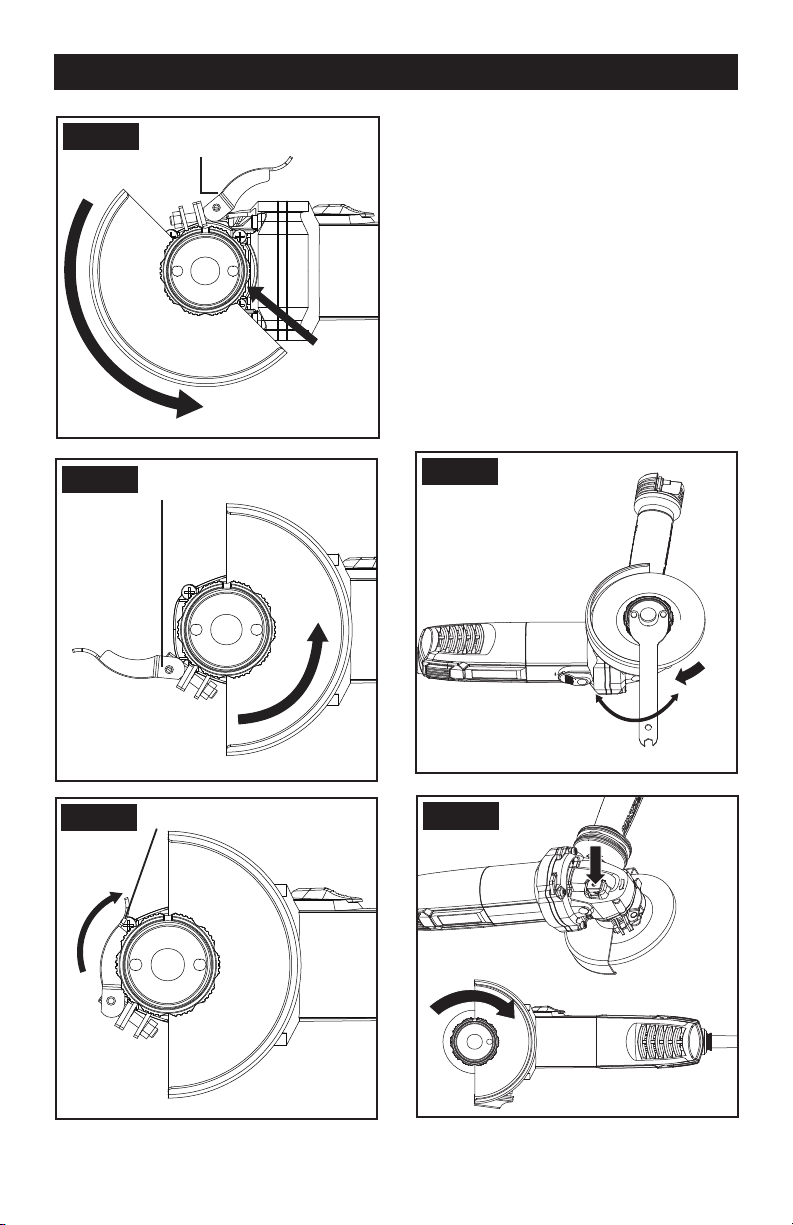
Open Guard Clamping Lever
Insert and Turn
Counterclockwise
Fig. C
Projection
Fig. D
Working Position (Example)
Opened Guard Clamping Lever
Fig. E
Working Position (Example)
Closed Guard Clamping Lever
4. GRINDING/CUTTING DISC
Pay attention to the dimensions of the
grinding disc. The mounting hole diameter
must fit the inner flange (6) without play. Do
not use reducers or adapters.
When using a diamond cutting disc, take
care that the direction-of-rotation arrow on
the diamond cutting disc and the direction of
rotation of the machine (direction-of-rotation
arrow on the machine head) agree.
For mounting, see the Component list
illustration page.
Screw on the outer ange (5) and tighten
with the two-pin spanner (9). (See Fig. F-1)
For SDS ange, keep the lock button
pressed in and tightened the SDS ange
with hand. (See Fig. F-2)
Fig. F-1
Fig. F-2
OPERATION
Loading ...
Loading ...
Loading ...