
Loading ...
Loading ...
Loading ...
Page 11
OPERATION INSTRUCTIONS
NOTE: Before using the tool, read the
instruction book carefully.
This tool may cause hand-arm vibration
syndrome if its use is not adequately
managed.
Intended Use
The machine is intended for cutting, roughing
and brushing metal and stone materials
without using water. For cutting metal, a special
protection guard for cutting (accessory) must be
used.
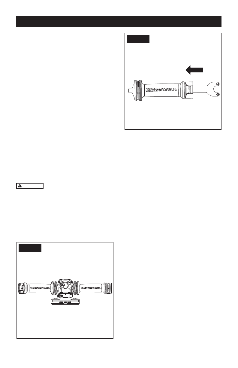
1. AUXILIARY HANDLE
For all work with the machine, the auxiliary
handle (3) must be mounted.
Screw the auxiliary handle (3) on the right or left
of the machine head depending on the working
method. (See Fig. A)
Your tool is equipped with an auxiliary handle
that can be used for storage of the spanner.
(See Fig. B)
WARNING
Do not make any alterations to
the auxiliary handle.
Do not continue to use an auxiliary handle if
it is damaged.
Before any work on the machine itself, pull
the mains plug.
Grinding and cutting discs become very hot
while working; do not touch until they have
cooled.
Fig. A
Fig. B
2. SPINDLE LOCK BUTTON
Clean the grinder spindle and all parts to be
mounted. For clamping and loosening the
grinding tools, lock the grinder spindle (7)
with the spindle lock button (4).
Actuate the spindle lock button (4) only
when the grinder spindle is at a standstill!
3. INSTALLING AND ADJUSTING THE DISC
GUARD
Make sure the grinder is unplugged before
making any adjustments.
For work with grinding discs, the disc guard
must be mounted.
The projection on the disc guard ensures that
only a guard that ts this angle grinder can
be mounted. Raise the guard clamping lever
(See Fig. C).
To install the guard align the guard projection
with the matching groove on the spindle
housing (See Fig. C). Push the guard down as
far as it will go.
Rotate the guard to a working position (See
Fig. D example).
NOTE: working position is with the closed side
of the guard toward the operator and open
side pointing directly away from the operator
to provide maximum protection against sparks
and ying debris.
Close the clamping lever to tighten (See Fig.
E example).
OPERATION
Loading ...
Loading ...
Loading ...