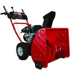
User Manual Snow Blower
ASSEMBLY
Overview
- Remove packaging materials from snow blower.
- Rotate Handle into the upright position. Refer to Handle Assembly.
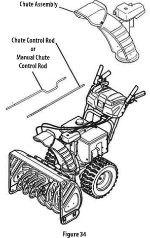
- Install the chute. Refer to Chute Assembly Options.
- Complete snow blower assembly according to model and equipment. Refer to Set-up.
- If necessary make adjustments to ensure proper snow blower operation. Refer to Adjustments.
- Add fuel and oil. Refer to the Engine Operator's Manual
- shipped with snow blower.
Tools Required
- Adjustable Wrench or Socket Set
- Needle Nose Pliers
Handle Assembly
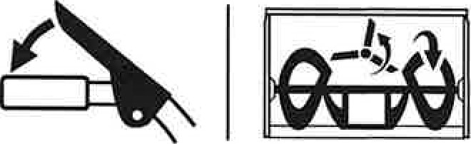
- Cut cable ties securing chute control rod or upper handle to the lower handle (if applicable), set aside the chute control rod (if applicable) and remove the wrap around the handles (inapplicable).
NOTE: Do not cut the cable tie securing the control cables to the engine, if equipped.
NOTE: On models with Overhead Chute Control (with Flex Shaft), Four-Way Chute Control, and Electric Chute Control cut cable ties securing flex shaft to the lower handle and set the flex shaft aside. Remove rubber bands securing cables to carriage bolts and cut cable tie securing shift rod to lower handle. Refer to Figure 7 to help identify the control styles.
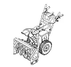
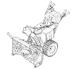
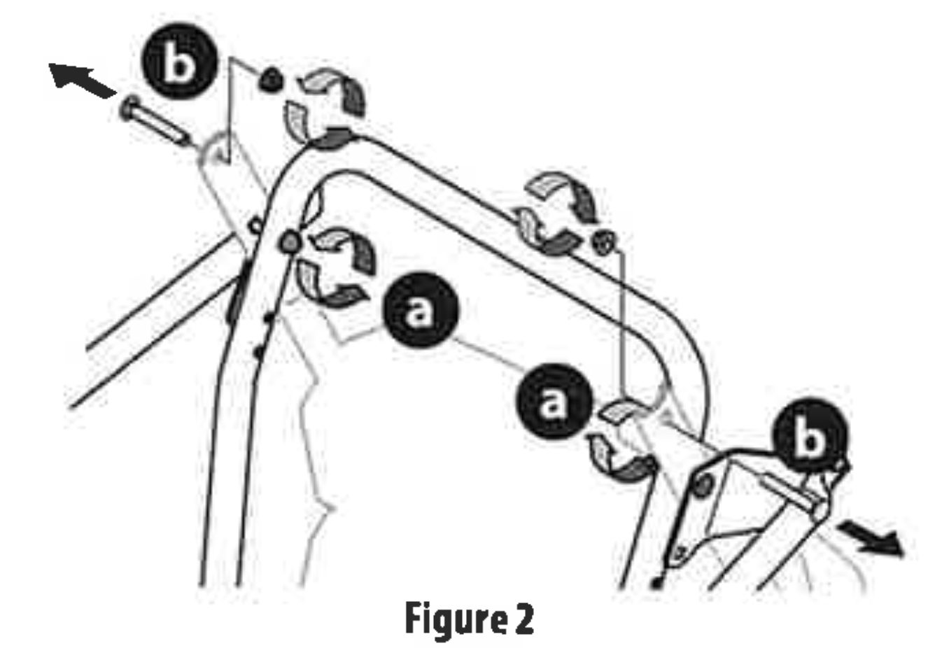
- Loosen the top two nuts (a) securing the upper and lower handle and remove the two carriage bolts (b) from the upper handle and set aside as shown in Figure 1 or Figure2 for models with side supports.

- Place shift lever in Forward-6 position or fastest forward speed (if equipped).
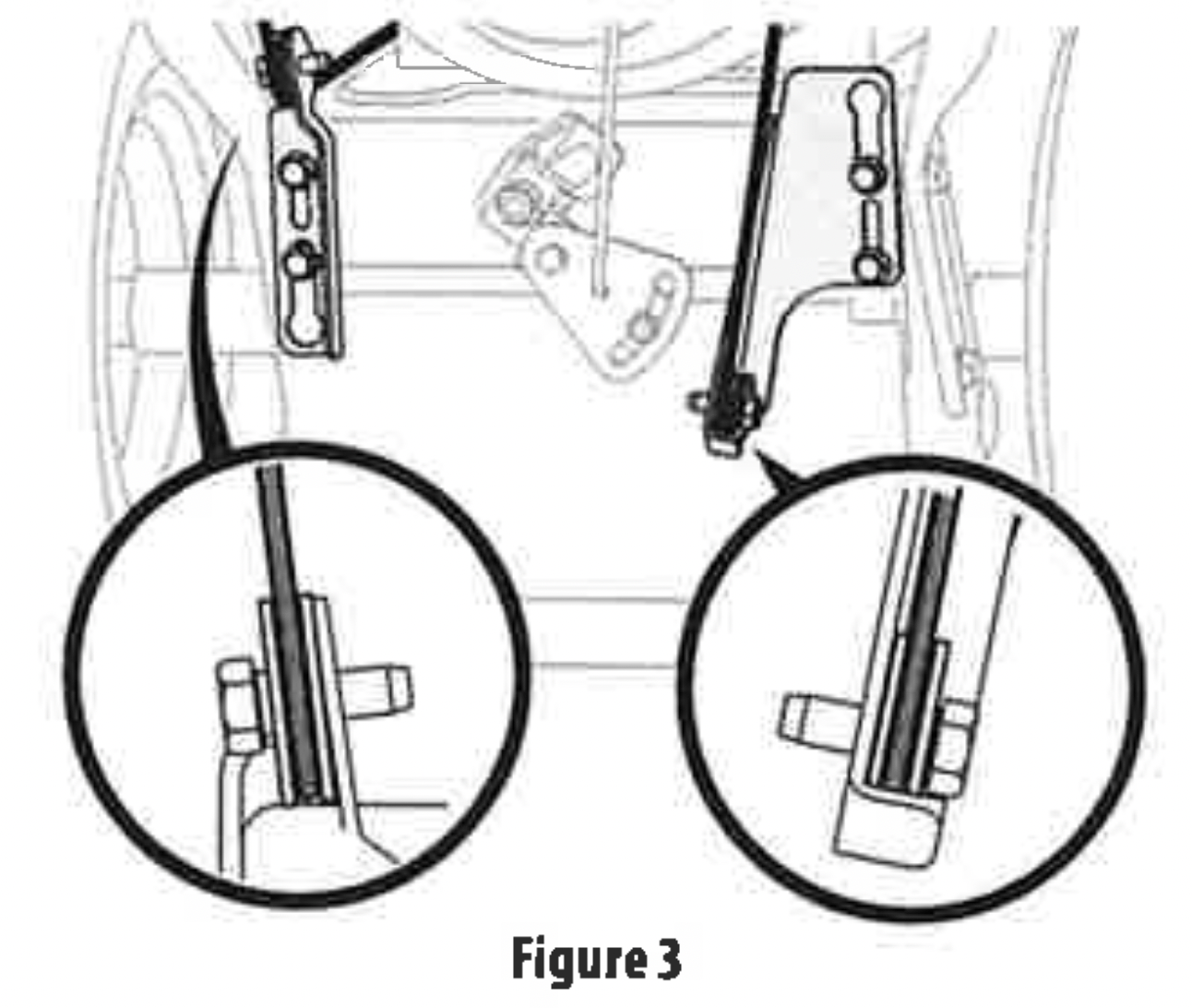
- Observe lower rear area of equipment to be sure both cables (if equipped) are aligned and seated properly In roller guides (Figure 3).
- Pivot handle upward and align the lower handle (Figure4). Remove and discard any rubber bands, if present. They are for packaging purposes only.
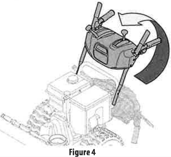
NOTE: On selectt models with steel rod speed selectors, you may need to lower shift rod to the side slightly to maneuver handle panel over it when pivoting handle upward.
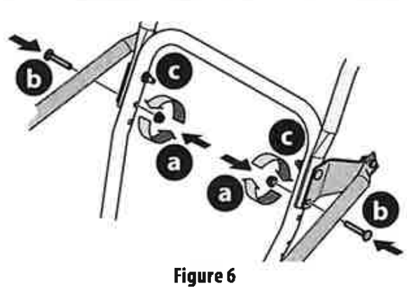
- Attach the two carriage bolts (b) and nuts (a) removed in Step 2. Finish securing the handle by tightening the top two nuts (c) loosened in Step 2. See Figure 5 or Figure 6 for models with side supports.

Chute Control Styles
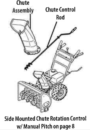


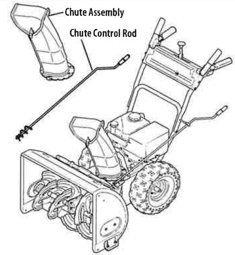
Side Mounted Chute Rotation Control w/ Manual Pitch
- Possition chute assembly over base (Figure 9)
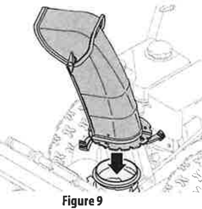
- Close flange keepers to secure chute assembly to chute base. Flange keepers will click into place when properly secured (Figure 10).

- Remove plastic cap (if present), flat washer (a) and hairpin clip (b) from end of chute control rod (Figure 11).
- Insert end of chute control rod into lower bracket and secure with flat washer (a), hairpin clip (b) and plastic cap (if present) removed in Step 1. If necessary, lower bracket can be adjusted. Refer to Side Chute Control on page 16.
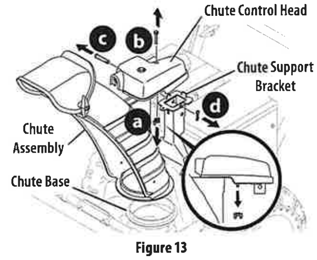
Overhead Chute Rotation Control w/ Manual Pitch
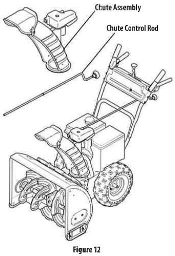
- Remove wing nut (a) and hex screw (b) from chute control head and clevis pin (c) and cotter pin (d) from chute support bracket. Position chute assembly (forward-facing) over chute base and chute support bracket (Figure 13).
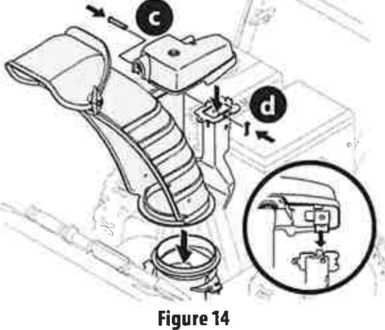
- Secure chute control head to chute support bracket with clevis pin (c) and cotter pin (d) removed in Step 1 (Figure 14).
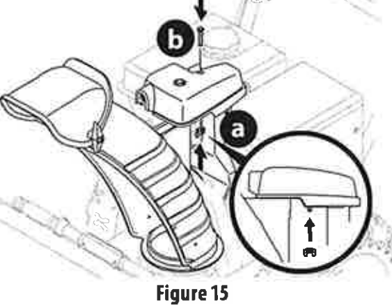
- Finish securing chute control head to chute support bracket with wing nut (a) and hex screw (b) removed in Step 1 (Figure 15).
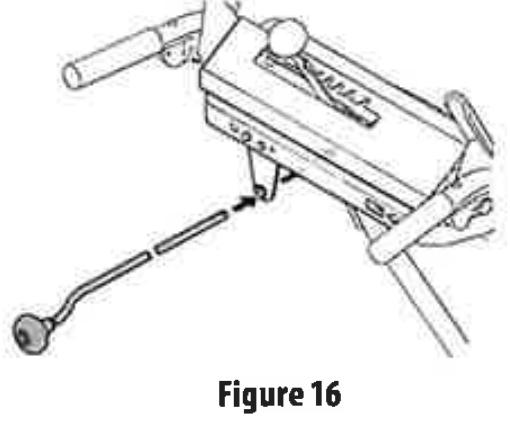
- Insert chute control rod into the support bracket on rear of the dash panel (Figure 16).
- Remove hairpin clip (a) from rear of chute control head (Figure 17).
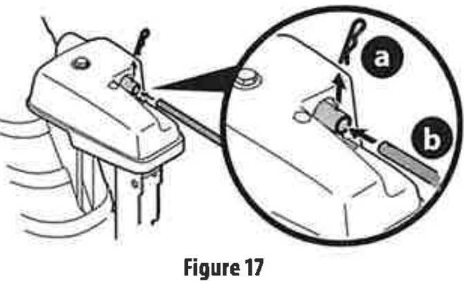
- Insert chute control rod (b) into rear of chute control head (Figure 17) and secure with hairpin clip (a) removed in Step 5
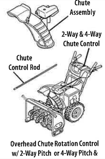
Overhead Chute Rotation Control w/2-Way Pitch or 4-Way Pitch & Rotation Control

- Remove hairpin clip (a), wing nut (b) and hexscrew (c) from chute control head and clevis pin (d) and bow-tie cotter pin (e) from chute support bracket (Figure 19).

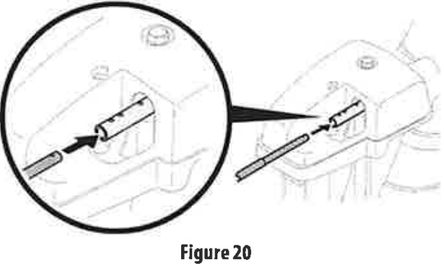
- Insert chute control rod into chute control head. Push rod as far into chute control head as possible, keeping holes in rod pointing upward (Figure 20).
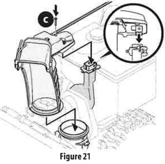
- Place chute assembly onto chute base and ensure chute control rod is positioned above lower handle. Install hex screw (c) removed in Step 1, but do not secure with wing nut at this time (Figure 21).
- Squeeze trigger on 2-way/4-way chute control and rotate chute by hand to face forward. The holes in chute control collar will be facing up (Figure 22).
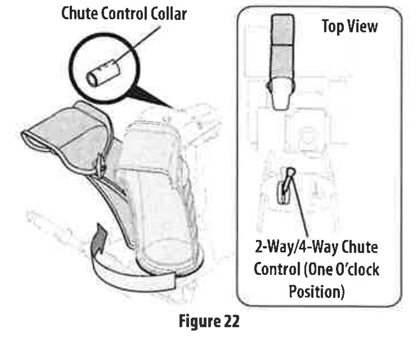
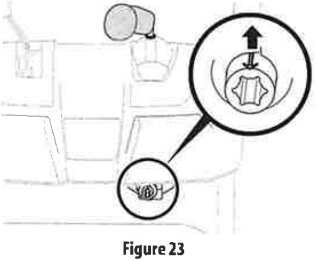
- Rotate 2-way/4-way chute control to one o'clock position (Figure 22) so that indicator arrow on pinion gear below control handle faces upward (Figure 23).
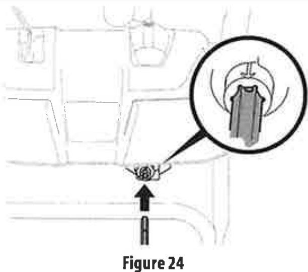
- Insert chute control rod into pinion gear under handle panel. Make sure to line up hole in rod with arrow on pinion gear(Figure 24).
- Push chute control rod toward control panel until hole in rod lines up with hole in chute control input collar closest to chute control head and insert hairpin clip (a) removed in Step 1 (Figure 25).

- Finish securing chute control head to chute support bracket with wing nut (b), clevis pin (d), and bow-tie cotter pin (e) removed in Step 1.
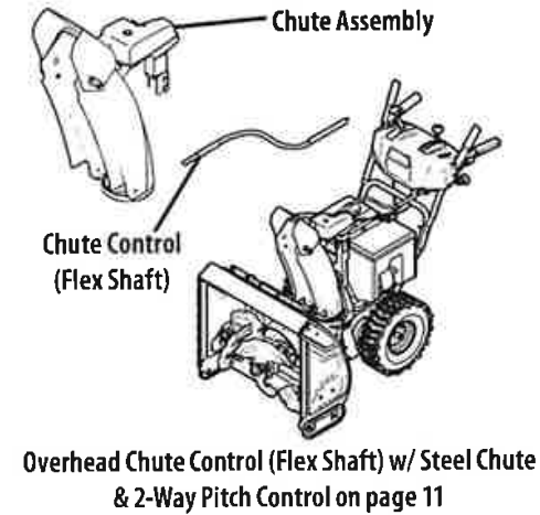
Overhead Chute Control (Flex Shaft) w/ Steel Chute & 2-Way Pitch Control

- Remove lock nuts (a) and hex screws (b)from chute support bracket (this will require two wrenches) (Figure 27).
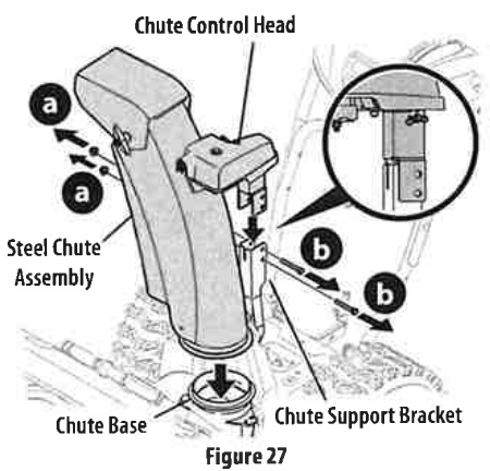
- Place steel chute assembly onto chute base and chute control head onto chute support bracket (Figure 27).
- Secure chute control head to chute support bracket with lock nuts (a) and hex screws (b) removed in Step 1 (Figure 28).

- Remove hairpin clip (a) from rear of chute control head (Figure 29).
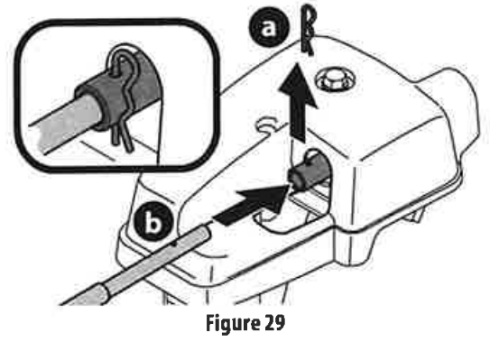
- Insert flex shaft (b) into rear of chute control head and secure with hairpin clip (a) removed in Step 4 (Figure 29).
- Perform one of the following to connect the flex shaft to the chute control rod coupling:
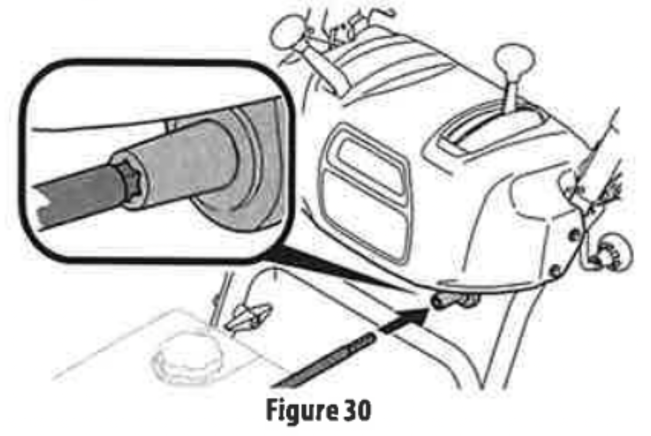
Models with Overhead Rotational - Insert hex end of flex shaft into chute control rod coupling under handle panel (Figure 30).
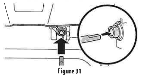
Models with Electric Chute Control - Insert other end of flex shaft into chute control rod coupling under handle panel. Make sure to line up flat end of rod and flat end of coupler. You may need to rotate rod around until these two surfaces line up (Figure 31 inset).
- Ensure speed selector is in fastest forward speed.
- Remove cotter pin (a) and washer (b) from ferrule on end of shift rod (Figure 32 inset).
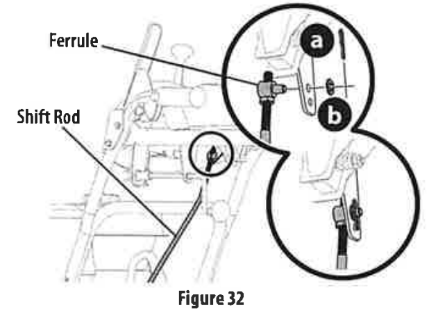
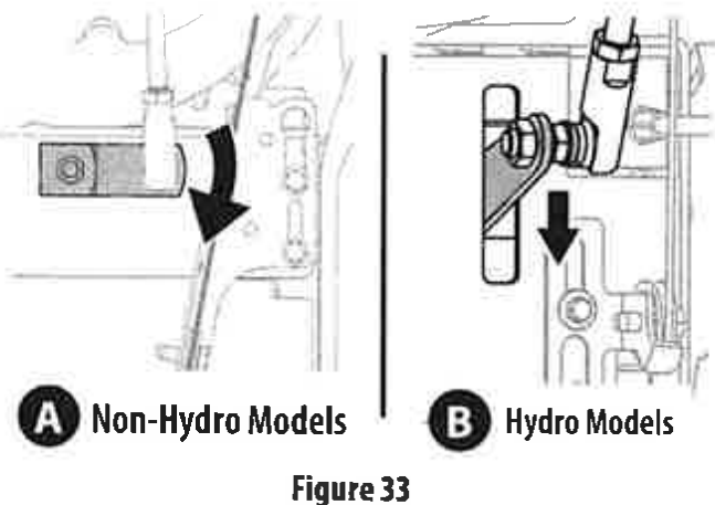
- Make sure the shift lever on the back of the transmission is rotated downward to the full extent of its rotation see Figure 33, Detail "A" for models without hydro transmission or Detail "B" for models with hydro transmission.
- Insert ferrule into top hole of shift lever and secure with cotter pin (a) and washer (b) removed in Step 8 (Figure 32). Ferrule may need to be adjusted up or down.
Overhead Chute Rotation Control w/4-Way Electric Pitch & Rotation Control
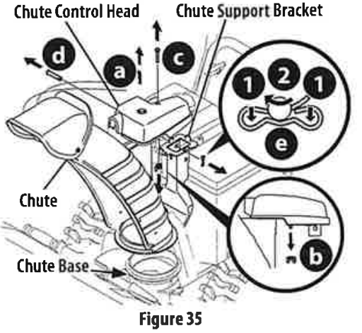
- Remove cotter pin (a), wing nut (b) and hex screw (c) from chute control head. Remove clevis pin (d) and bow-tie cotter pin (e) from chute support bracket (Figure 35).
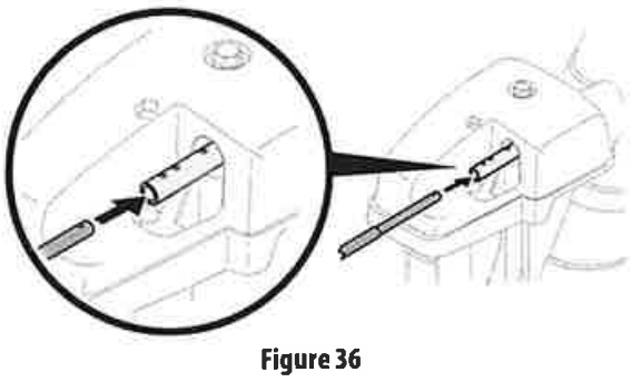
- Insert round end of chute control rod into chute control head. Push rod as far into chute control head as possible, keeping holes in rod pointing upward (Figure 36).
- Place chute onto chute base and ensure chute control rod is positioned above lower handle. Secure chute control head to chute support bracketwith clevis pin (d) and bow-tie cotter pin (e) removed in Step 1 (Figure 37).
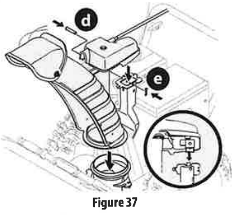
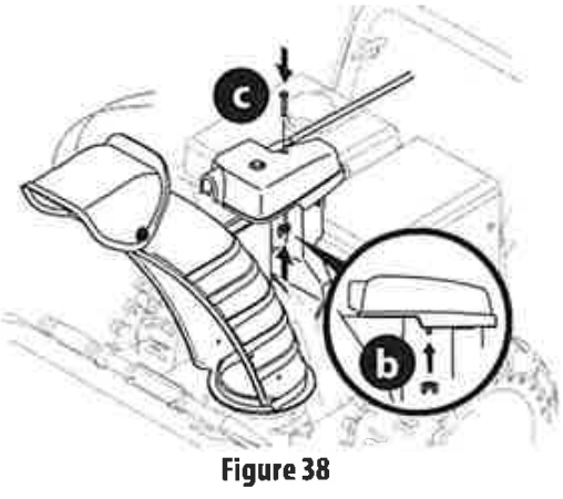
- Finish securing chute control head by installing hex screw (c) and wing nut (b) removed in Step 1 (Figure 38).
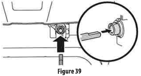
- Insert other end of chute control rod into coupler below handle panel. Make sure to line up flat end of rod and flat end of coupler. You may need to rotate rod around until these two surfaces line up (Figure 39 inset).
- Push chute control rod toward the control panel until hole in rod lines up with middle hole in chute control coupler and insert cotter pin (a) removed in Step 1 (Figure 40).

Set-Up
CHUTE CONTROL CABLE ROUTING (IF EQUIPPED)
For models equipped with 2-way or 4-way chute controls, electric chute control and/or chute-pitch controls, ensure control cables a re routed properly.
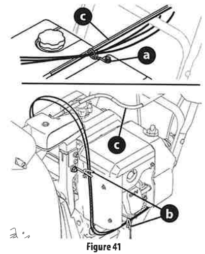
Chute control cables are routed through a single wire guide (a) on top of the engine and/or through two wire guides (b) located on the front and left side of the engine (Figure 41).
NOTE :On models equipped with a cable tie securing the cables to the rear of the gas tank, pull the cables toward the chute and pull the cable tie snug to secure the cables in place.
NOTE: For smoothest operation, cables should all be to the left of the chute control rod (c).
NOTE : The number of cables routed through the wire guides will vary depending on model,
- Locate cable guide(s) and perform the following:
Top Mounted Wire Guide (a) - Check that all cables are properly routed through cable guide on top of engine (Figure 41).
Front and Side Mounted Wire Guides (b) - Check that all cables are properly routed through the wire guide below the left side of the engine and the wire guide below the chute control head (Figure 41).
SHEAR PINS STORAGE (IF EQUIPPED)
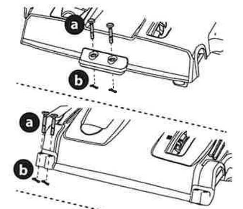
On select models, holes are provided in the rear of the handle panel for shear pin (a) and bow-tie cotter pin (b) storage as shown in Figure 42.
If not provided, make sure to store them in a safe place until needed

DRIFT CUTTERS (IF EQUIPPED)
The drift cutters are mounted inverted at the factory for shipping purposes.
Non-Adjustable
- Remove two carriage bolts (a) and lock nuts (b)that secure each drift cutter, and remove them from the sides of auger housing (Figure 43).
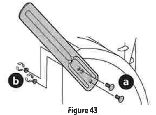
- Turn the drift cutters around and position them as shown in Figure 43 to the outside of the auger housing.
- Attach drift cutters with carriage bolts (a) and lock nuts (b) removed in Step 1.
Tool-less
- Remove two carriage bolts (a) and wing nuts (b) that secure each drift cutter, and remove them from the sides of auger housing (Figure 44).
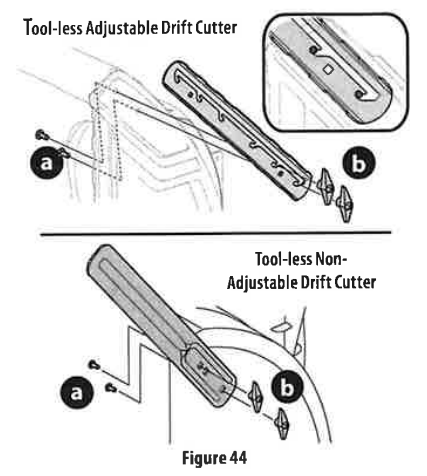
- Turn the drift cutters around and position them as shown in Figure 44 to the outside of the auger housing.
- Attach drift cutters with carriage bolts (a) and wing nuts (b) removed in Step 1.
SKID SHOES (IF APPLICABLE)
Select models require the installation to the provided skid shoes.
- Using the two carriage bolts (a) and hex flange nuts (b) and flat washers (if equipped) (c), secure the skid shoes to the auger housing (d). Hand tightens hex flange nuts (Figure 45).
- Adjust the skid shoes to provide a minimum of 1/8th inch clearance between the shave plate (e) and the ground. Securely tighten hex flange nuts
- If necessary refer to Skid Shoes in the Adjustment section on page 15

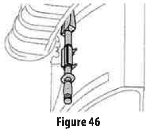
CHUTE CLEAN-OUT TOOL
The chute dean-out tool is fastened to the top of the auger housing with a mounting clip (Figure 46).
TIRE PRESSURE (IF APPLICABLE)
The tires are over-inflated forshipping purposes. Check tire pressure before operating. Refer to tire side wall for tire manufacturer's recommended psi and adjust pressure, if necessary.
Adjustments
SKID SHOES
Snow blower skid shoes are adjusted at a factory setting roughly 1/8" below the shave plate. Adjust them upward or downward, if desired, prior to operating.
- For close snow removal on a smooth surface, raise skid shoes higher on auger housing.
- Use a lower position when area to be cleared is uneven, such as a gravel driveway.
- Loosen four hex nuts (a) (two on each side) and carriage bolts (b). Move skid shoes to desired position (Figure 47).

- Make certain entire bottom surface of skid shoe is against ground to avoid uneven wear on skid shoes.
- Securely tighten hex nuts (a) to carriage bolts (b).
ADJUSTMENTS
ADJUSTABLE DRIFT CUTTERS (IF EQUIPPED)
The drift cutters are mounted inverted at the factory for shipping purposes.
- Loosen the two carriage bolts (a) and wing nuts (b) that secure each drift cutter to the sides of auger housing (Figure 48).
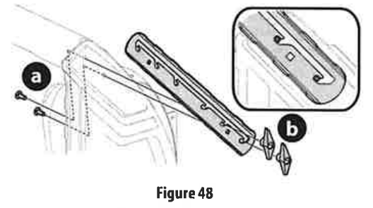
- Slide the drift cutters to desired height.
- Securely tighten the two carriage bolts and wing nuts that secure each drift cutter to the sides of auger housing
MANUAL CHUTE PITCH ADJUSTMENT (IF EQUIPPED)
NOTE: For models without manual chute pitch, see Controls and Operation on page 21-22.
On models with manual chute pitch, the distance snow is thrown can be adjusted by changing angle of chute assembly. To do so:
- Loosen wing nut found on leftsideofthe upper chute assembly (Figure 49).
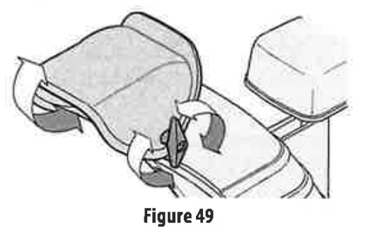
- Pivot chute upward or downward before re-tightening wing nut.
SIDE CHUTE CONTROL (IF EQUIPPED)
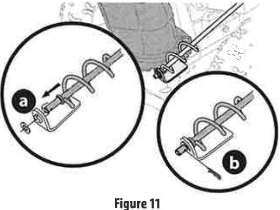
If spiral at bottom of the chute control rod is not fully engaging with chute assembly, the bracket needs to be adjusted. To do so:
- Loosen two nuts (a) which secure the bracket and reposition it slightly (Figure 50).
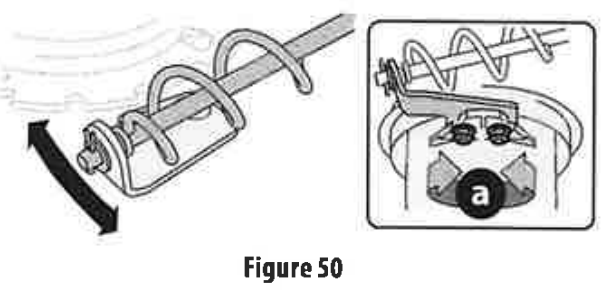
- Re-tightennuts.
OVERHEAD CHUTE CONTROL (IF EQUIPPED)
If chute fails to remain stationary during operation, preload of chute can be adjusted by tightening hex nut found on front of chute control head.
- To increase preload, tighten hex nut (a) clockwise in M turn intervals. The chute control rod (b) will need to be held stationary when tightening the nut (Figure 51).

- If chute control rod is difficult to turn, decrease preload by loosening hex nut counter-clockwise in % turn intervals.
2 WAY OR 4-WAY CHUTE CONTROL (IF EQUIPPED)
To adjust chute control rod for increased engagement into the handle panel control, proceed as follows:
- Remove hairpin dip (a) from hole closest to chute assembly on chute control head.
- Pull out chute control rod until hole in it lines up with second hole in chute control head (Figure 52).
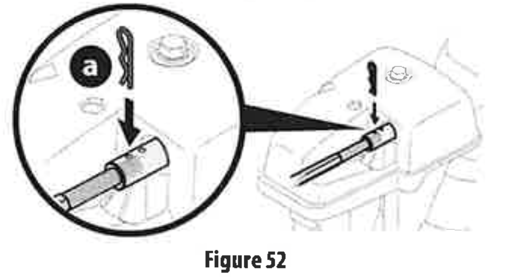
- Reinsert hairpin clip (a) through this hole and chute control rod.
ADJUSTABLE SHAVE PLATE (IF EQUIPPED)
- Allow engine to run until it is out of fuel. Do not attempt to drain fuel from the engine. Remove safety key or disconnect sparkplug wire.
- Carefully pivot snow blower up and forward so that it rests on front of auger housing.
- Loosen rear skid shoe nuts (a) on both sides of auger housing and remove carriage bolts (b) and hex nuts (c) which attach shave plate (d) to the bottom of the auger housing (Figure 53).
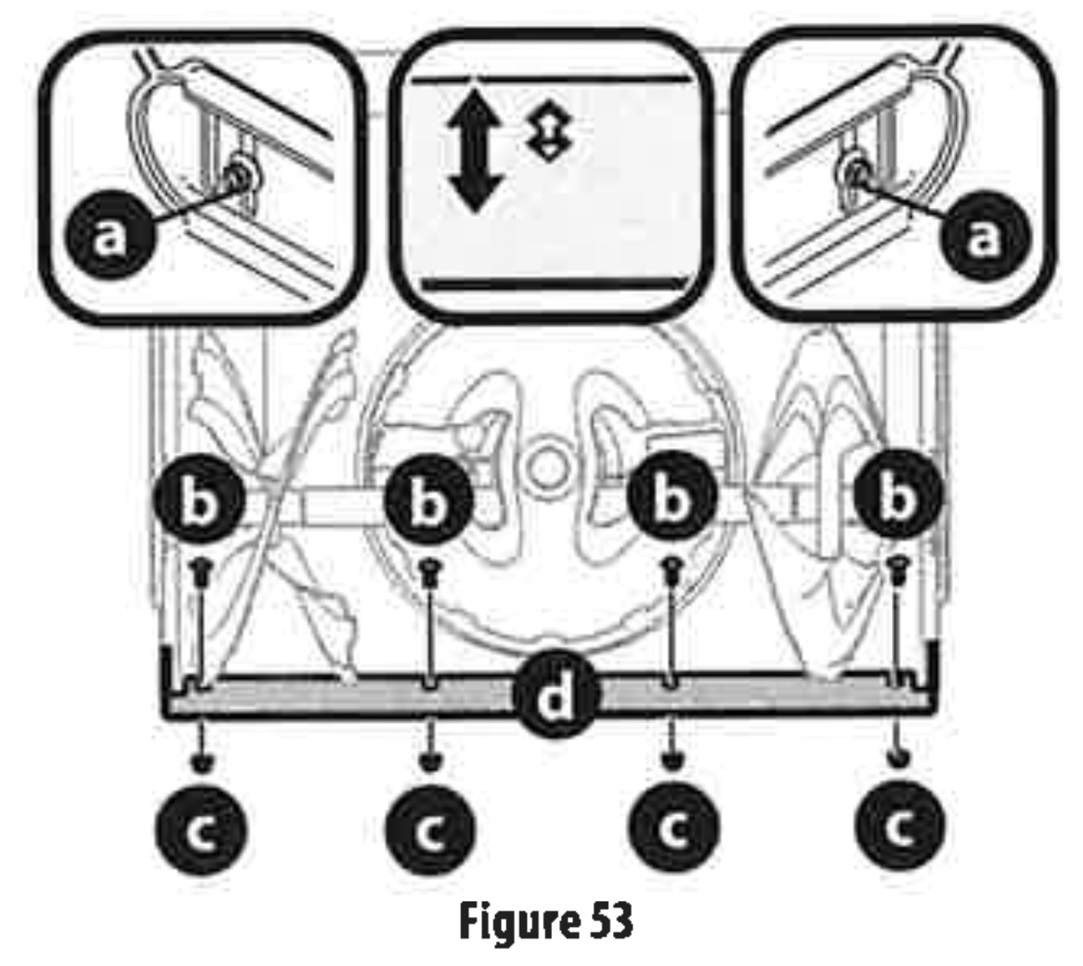
- Adjust the shave plate to one of 2 mounting positions. Reinstall and securely tighten all carriage bolts, nuts and skid shoe hardware from Step 3 (Figure 53).
- Readjust the skid shoes. See Skid Shoes on page 15.
AUGER CONTROL
Refer to Controls & Operation section on page 20 for the location of auger control lever and check adjustment as follows:
- When auger control lever is released and in disengaged "UP" position, the cable should have very little slack. It should NOT be tight.
- In a well-ventilated area, start the engine. Refer to your Engine Operator's Manual.
- While standing in the operator's position (behind the handles), depress the auger control lever to engage auger.
- Allow auger to remain engaged for approximately ten (10) seconds before releasing auger control lever. Repeat this several times.
- With auger control lever in disengaged "UP" position, walk to front of machine.
- Confirm that auger has completely stopped rotating and shows NO signs of motion. If auger shows ANY signs of rotating, immediately shut OFF engine, remove safety key or disconnect spark plug wire. Wait for ALL moving parts to stop before readjusting auger control lever.
- To readjust the auger control cable, loosen upper hex screw (a) (Figure 54).
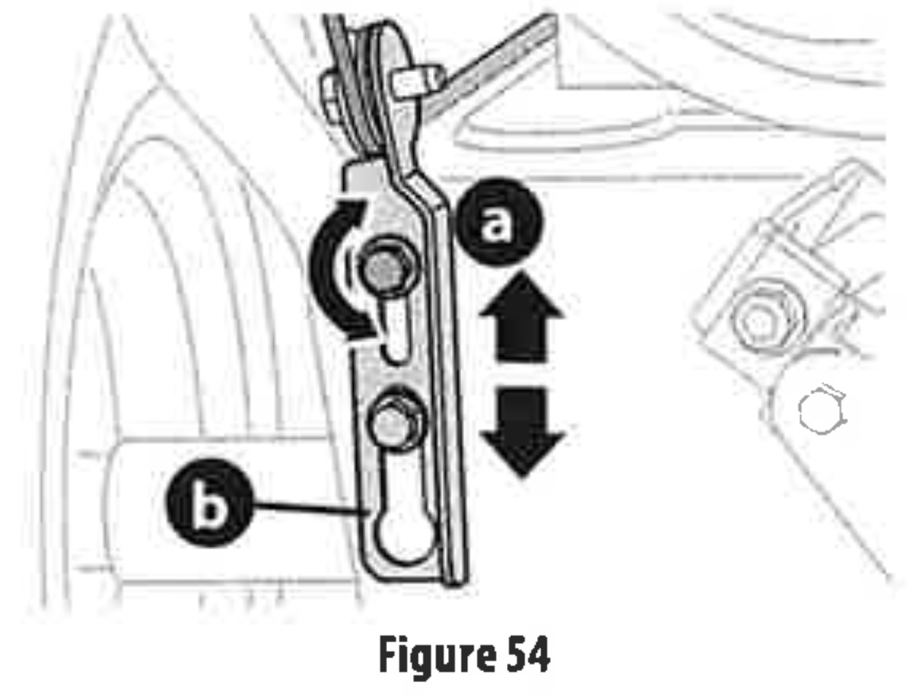
- Position auger control bracket (b) upward to provide more slack in cable or downward to increase tension (Figure 54).
- Re-tighten upper/rear hex screw (a).
- 1Repeat the steps 1 6 to verify proper adjustment has been achieved.
SHIFT CABLE (IF EQUIPPED)
If full range of speeds (forward and reverse) cannot be achieved,
adjust shift cable as follows:
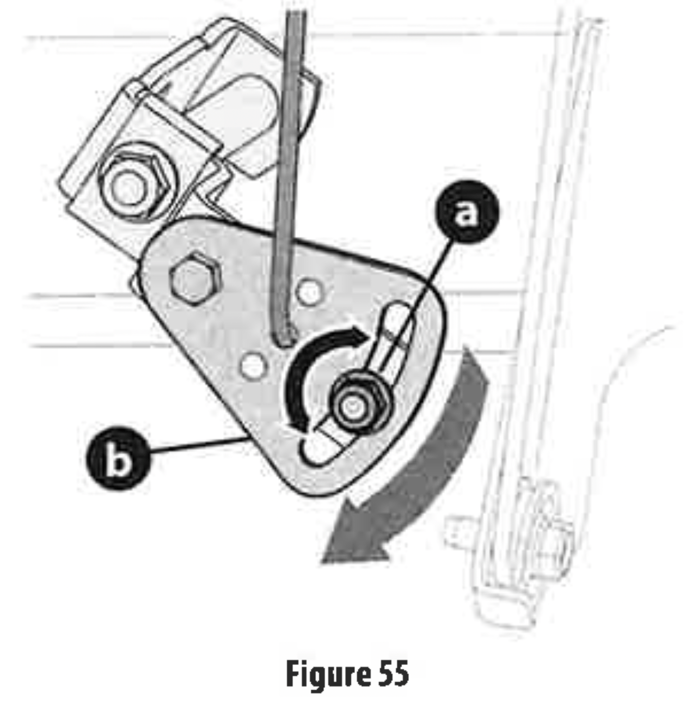
- Place shift lever in fastest forward speed position.
- Loosen hex nut (a) on shift cable index bracket (b) (Figure 55).
- Pivot bracket downward to take up slack in cable.
- Re-tighten hex nut.
- If further adjustment is necessary move the shift cable to one of the alternate holes in the shift cable index bracket.
SHIFT ROD (IF EQUIPPED)
If full range of speeds (forward and reverse) cannot be achieved, adjust shift rod as follows:
- Place shift lever in fastest forward speed position.
- Remove cotter pin (a) and washer (b) From adjustment ferrule on shift rod and pull it out from shift lever (Figure 56).
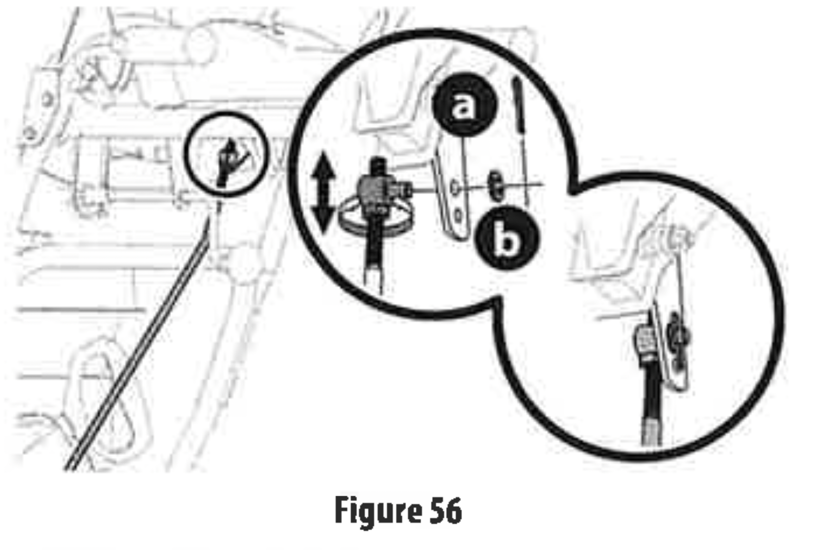
- Make sure the shift lever on the back of the transmission is rotated downward to the full extent of its rotation. See Figure 57, Detail “A" for models without hydro transmission or Detail "B" for models with hydro transmission.
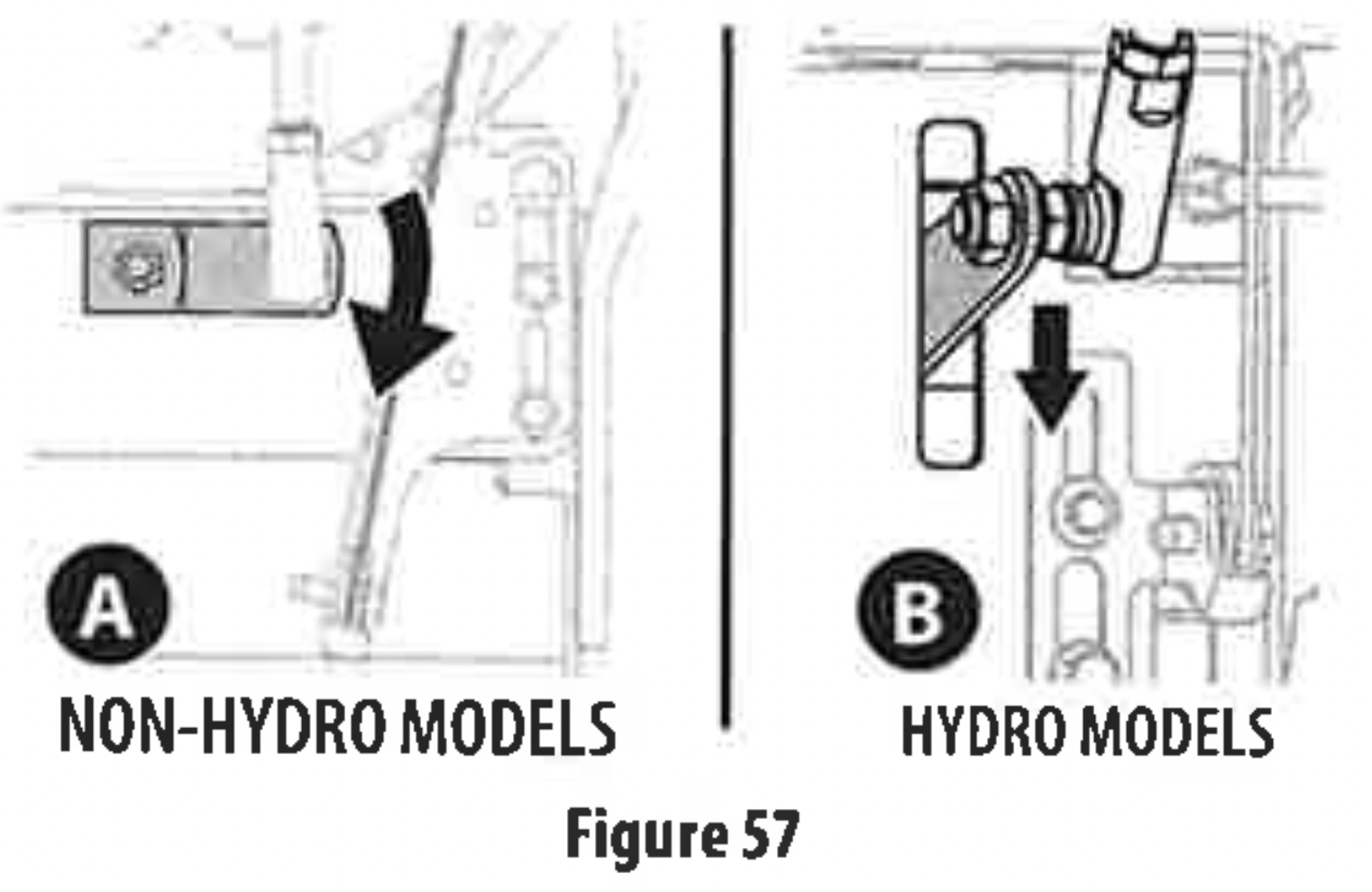
- Rotate ferrule up or down on shift rod as necessary until it lines up with upper hole in shift lever (Figure 57 inset).
- Insert the ferrule into the upper hole and secure with the washer and cotter pin.
DRIVE CONTROL (NON-HYDRO MODELS) (IF EQUIPPED)
When drive control lever is released and in disengaged "UP” position, cable should have very little slack. It should NOT be tight.
Check adjustment of drive control lever as follows:
- With drive control lever released, push snow blower gently forward. It should roll freely
- Engage drive control lever and gently attempt to push the snow blower forward. The wheels should not rotate or roll freely.
- If equipped with a shift lever, with drive control lever released, move shift lever back and forth between the R2 position and the F6 position several times. There should be no resistance in the shift lever.
If any of the above tests fail, the drive cable is in need of adjustment. Proceed as follows:
- Shut OFF engine, remove safety key or disconnect spark plug wire. Refer to the Engine Operator's Manual.
- Loosen lower hex screw (a) on drive cable bracket (b) (Figure 58).
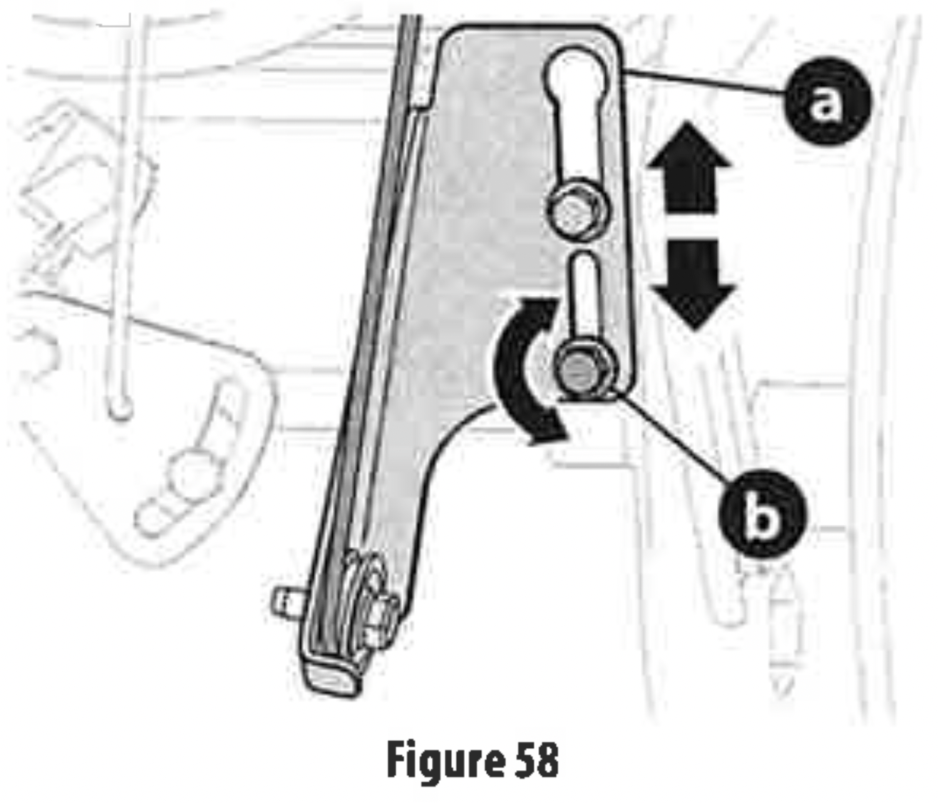
- Position drive cable bracket upward to provide more slack (or downward to increase cable tension).
- Re-tighten lower hex screw.
- Check adjustment of drive control lever as described above to verify proper adjustment has been achieved.
DRIVE CONTROL (HYDRO MODELS) (IF EQUIPPED)
When drive control lever is released and in disengaged "UP" position, cable should have very little slack. It should NOT be tight.
NOTE: If excessive slack is present in drive cable or if drive is disengaging intermittently during operation, the cable may be in needofadjustment.
- Shut OFF engine, remove safety key or disconnect spark plug wire. Refer to the Engine Operator's Manual.
- Loosen upper hex screw (a) on drive cable bracket (b) (Figure 59).

- Position bracket upward to provide more slack (or downward to increase cable tension).
- Re-tighten upper hex screw.
- Check for excessive slack in drive control cable. If necessary repeat Steps 2-4 to re-adjust the drive control.
Adding Fuel & Oil
Refer to the Engine Operator's Manual for information on adding fuel and oil.
OPERATION
Model Features

FEATURES
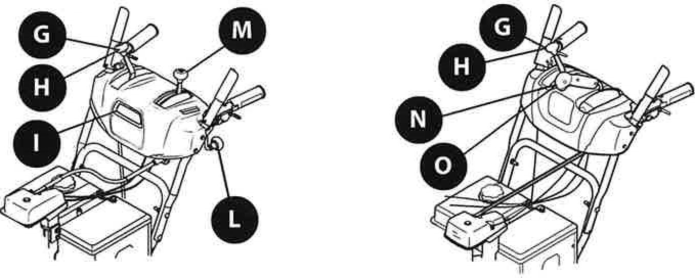
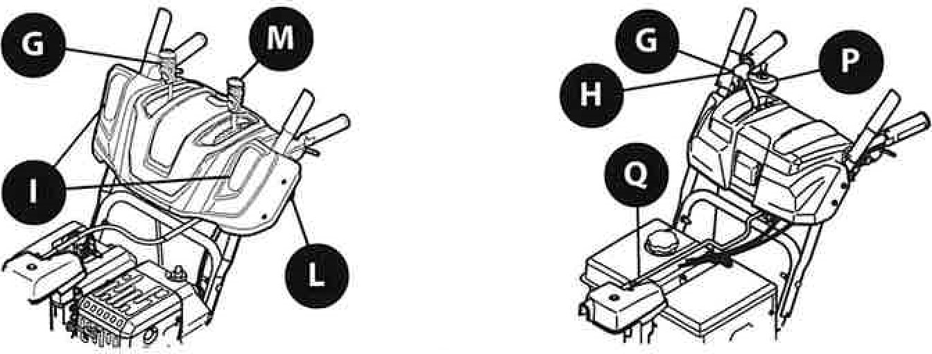
Snow blower controls and features are described below and may be illustrated in Figure 60.
NOTE: This Operator's Manual covers several models. Snow blower features may vary by model. Not all features in this manual are applicable to al} snow blower models and the snow blower depicted may differ from yours.
NOTE: All references to the left or right side ofthe snow blower are from the operator's position. Any exceptions will be noted.
A. ENGINE CONTROLSRefer to your Engine Operatoffs Manual for location and description of engine controls pertaining to your engine.
B. CHUTE ASSEMBLY
Snow gathered into the auger and impeller housings is discharged out the chute assembly.
C. SKID SHOES
Skid shoes provide the proper clearance of the shave plate for the surface conditions and the snow to be cleared. Adjust upward for hard-packed snow. Adjust downward when operating on gravel or crushed rock surfaces. See Skid Shoe Adjustment section on page 15.
D. AUGERS
When engaged, the augers rotate and gather snow into the auger and impeller housings.
E. DRIVE CONTROL LEVER/AUGER CLUTCH LOCK* (IF EQUIPPED)
The drive control lever is located on the right handle. Squeeze the control lever down against the handle to engage the wheel drive.

NOTE: Always release drive control lever before changing speeds on all models except the hydro transmission models. Failure to do so will result in increased wear on your machine's drive system.
*On select models, the drive control lever also locks the auger control lever so that you can operate the chute control without interrupting the snow blowing process. When both the auger and drive levers are engaged at any time, the operator can release the auger control lever (on the left handle) and the augers wilt remain engaged. Release both control levers to stop augers and wheel drive.
F. AUGER CONTROL LEVER (IF EQUIPPED)
The auger control lever down is located on the left handle. Squeeze the control lever against the handle to engage the augers and start snow blowing action. Release to stop (Figure 62).
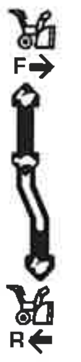
G. SHIFT LEVER (6-SPEED TRANSMISSION) (IF EQUIPPED)
The shift lever is located on the handle panel and is used to determine ground speed and direction of travel.
-
Forward
There are six forward (F) speeds. Position one (1) is the slowest and position six (6) is the fastest.
-
Reverse
There are two reverse (R) speeds. Position one (1) is the slowest and position two (2) is the fastest.
H. SHIFT LEVER (HYDRO TRANSMISSION) (IF EQUIPPED)
The shift lever is located on the handle panel and is used to determine ground spped and direction of travel. The further forward the lever is moved the faster it will travel. Moving past the detent position to the reserve direction will move the snow blower is reserve.
l. HEADLIGHT (SINGLE OR DUAL) (IF EQUIPPED)
The headlight(s) located on the front of the handle panel is/are automatically turned ON when the engine is started.
J. STEEING TRIGGER CONTROLS (IF EQUIPPED)
The left and right wheel steering trigger controls are located on the underside of the handles (Figure 63).
IMPORTANT: Models with Hydro Transmission - When moving the snow blower without starting the engine, squeeze both right and left triggers to disengage the drive.
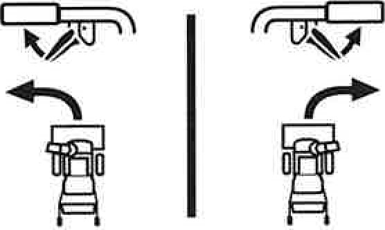
- Squeeze the right trigger controt to turn right.
- Squeeze the left trigger control to turn left.
K. SIDE MOUNTED CHUTE ROTATION CONTROL(IF EQUIPPED)
The side mounted chute rotation control is located on the left side of the snow blower. To change direction in which snow is thrown, rotate the control (Figure 64).
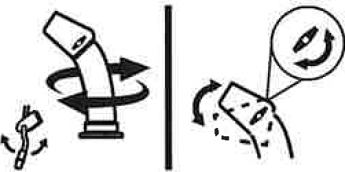
Figure 64
L. OVERHEAD CHUTE ROTATION CONTROL (IF EQUIPPED)
The overhead chute rotation control is located at the rear of the snow blower under the handle panel. To change the direction jn which snow is thrown, rotate the control (Figure 65).
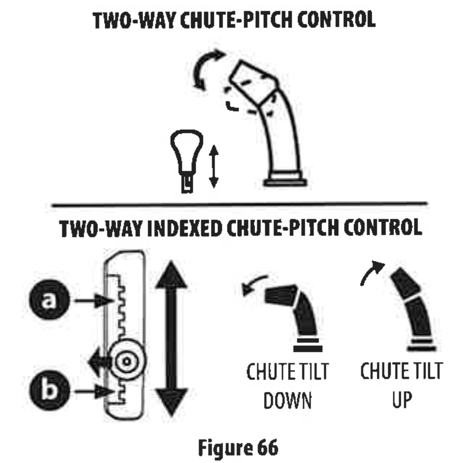
M. CHUTE-PITCH CONTROL (IF EQUIPPED)
The two-way chute-pitch control is located on the left side of the dash panel and is used to raise and lower the upper chute, which will change the distance the snow is thrown.
To raise or lower the upper chute, move the lever forward or backward (Figure 66).
Two-Way Chute-Pitch Control
- To Reduce the Distance Snow is Thrown: Move the lever forward to tilt the upper chute down (Figure 66).
- To Increase the Distance Snow is Thrown: Move the lever rearward to tilt the upper chute up (Figure 66).
Two-Way Indexed Chute-Pitch Control
- To Reduce the Distance Snow is Thrown: Disengage lever from the current chute setting. Move the lever forward to tilt the upper chute down to the desired setting(a) (Figure 66).
- To lncrease the Distance Snow is Thrown: Disengage lever from the current chute setting. Move the lever rearward to tilt the upper chute down to the desired setting(b) (Figure 66).
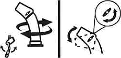
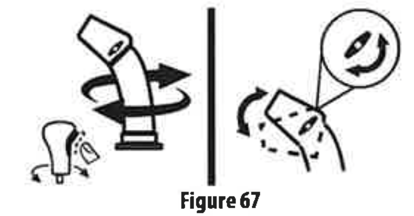
N.2-WAY CHUTE ROTATION CONTROL (IF EQUIPPED)
The 2-Way chute rotation control is located on the left side of the dash panel.
- To change direction in which snow is thrown, squeeze button on control and rotate to the right or to the left (Figure 67).
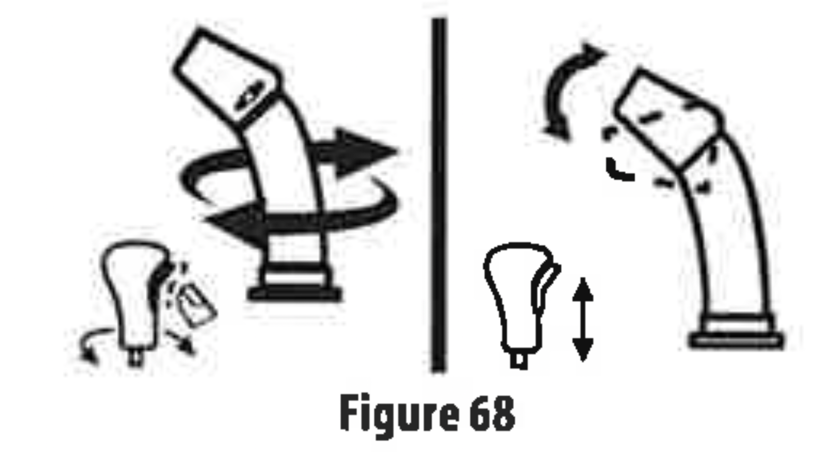
0.4-WAY CHUTE ROTATION CONTROL (IF EQUIPPED)
The 4-Way chute rotation control is located on the left side of the dash panel.
- To change the direction in which snow is thrown, squeeze the button on the control and rotate to the right or to the left (Figure 68).
- To change the distance which snow is thrown, move the control forward or backward.
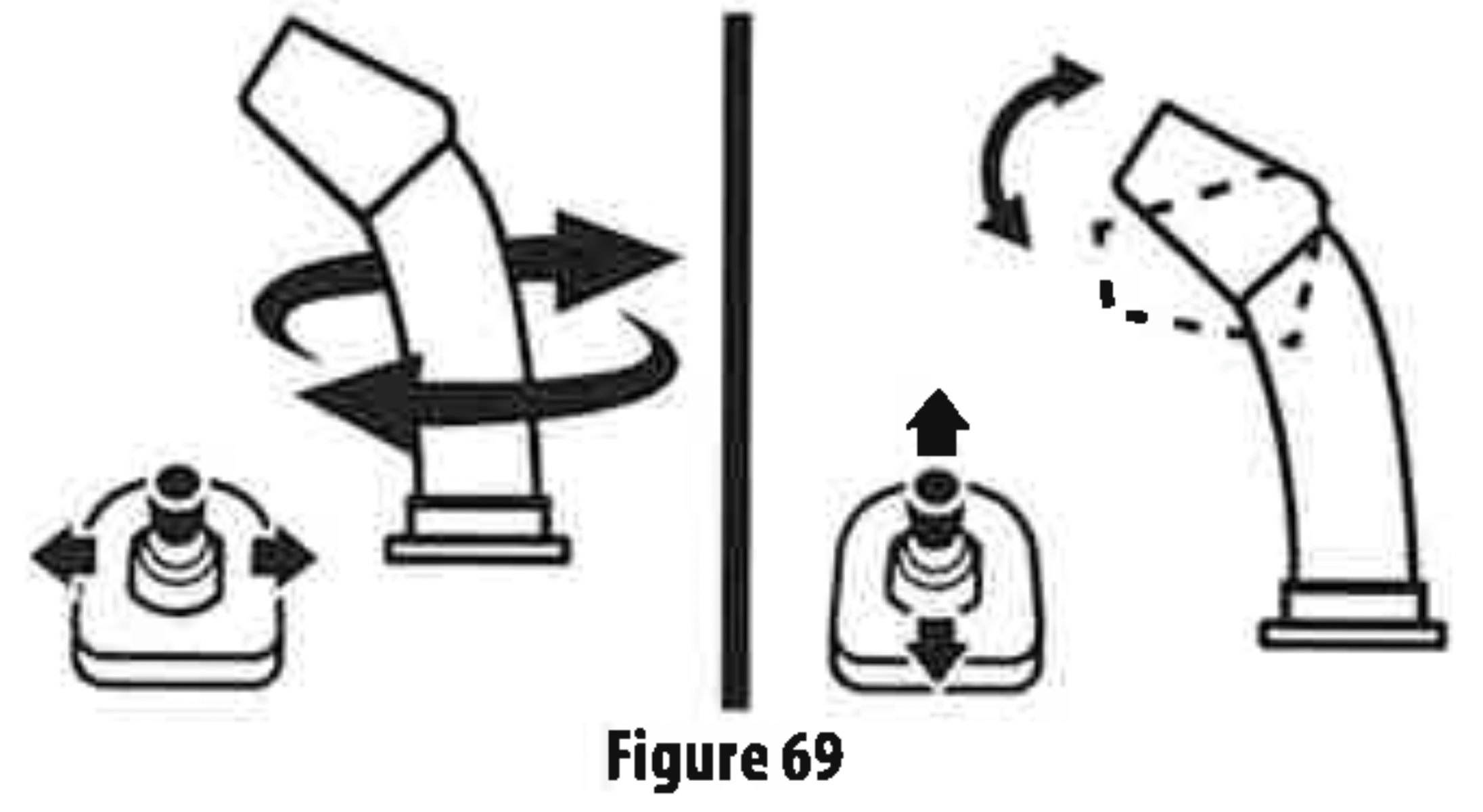
P. ELECTRIC CHUTE PITCH & ROTATION CONTROL (JOYSTICK) (IF EQUIPPED)
The electric chute control is located on the right side of the dash panel (Figure 69).
- To change the direction in which snow is thrown, move the joystick to the right or to the left.
- To change the distance which snow is thrown, move the joystick forward or backward.
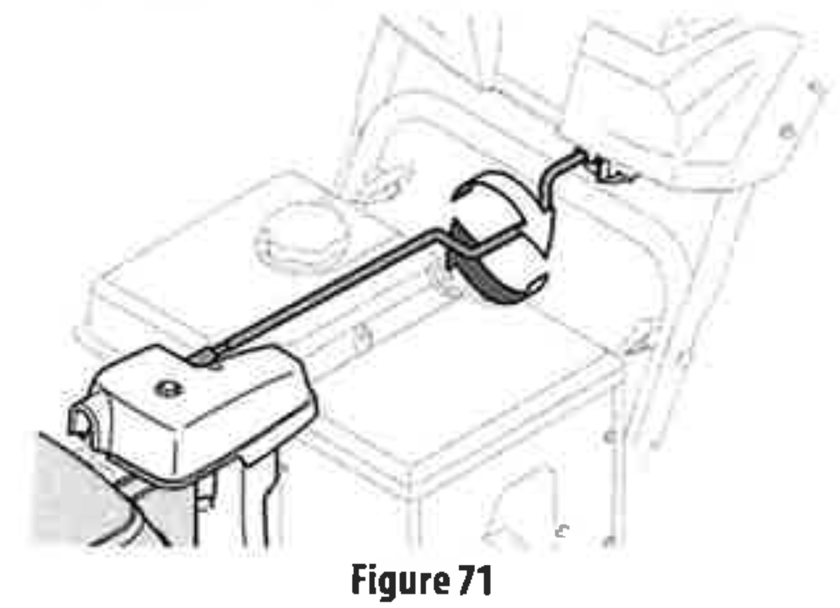
Q. MANUAL CHUTE ROTATION CONTROL & ELECTRIC CHUTE CONTROL (JOYSTICK) (IF EQUIPPED)
Follow this procedure to manually change the chute direction on models equipped with an electric chute control (joystick) and manual chute rotation control rod only (Figure 60).
- Remove cotter pin (a) from either of the holes furthest from the chute assembly on chute control head (Figure 70).
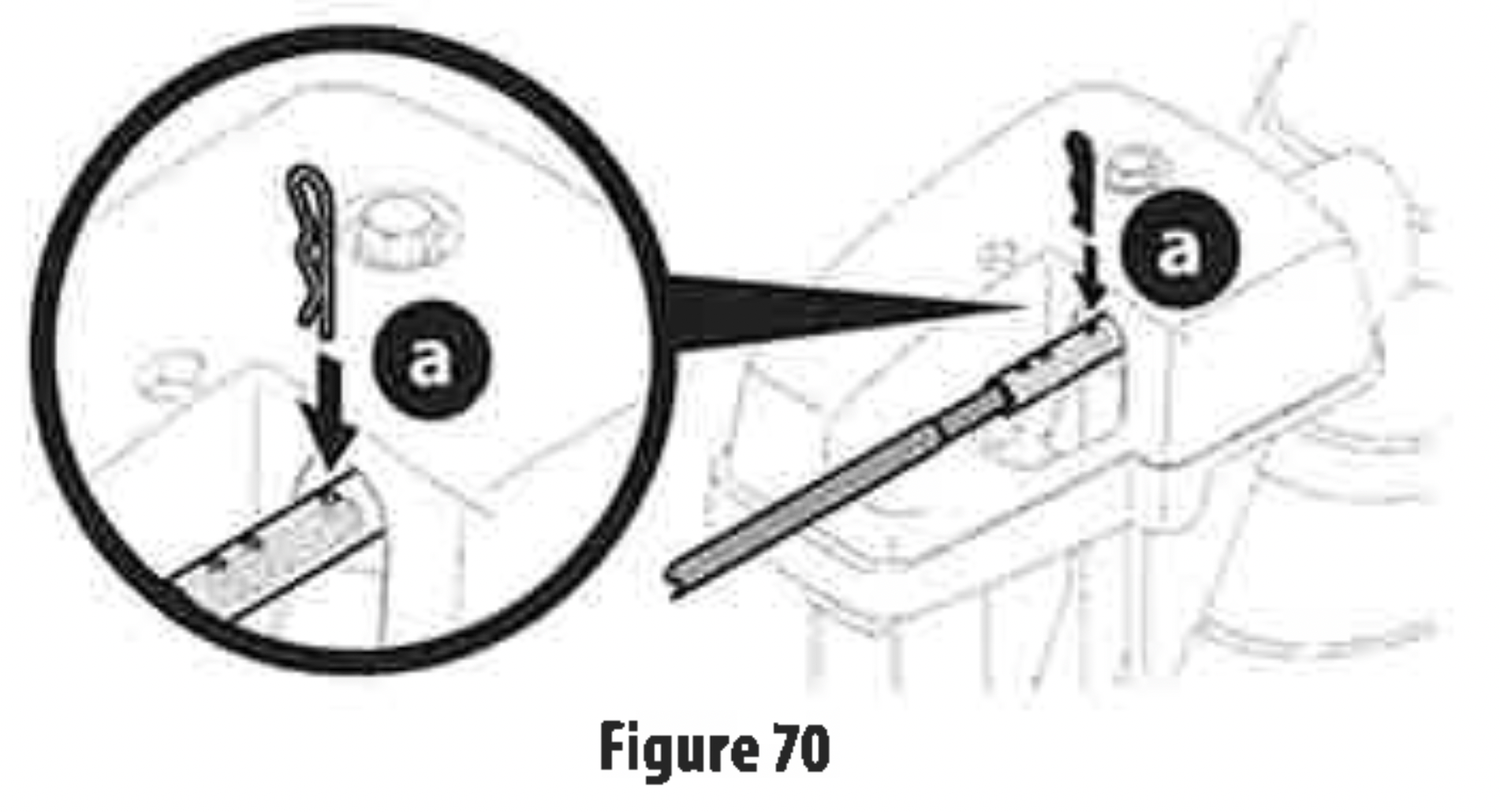
- Push in chute control rod until the hole in it lines up with the third hole in chute control head (Figure 70).
- Reinsert cotter pin(a) through this hole and chute control rod (Figure 70).
- Grasp indented portion of chute control rod and manually rotate chute assembly to the right or to the left (Figure 71).
R. LED LIGHT BAR (IF EQUIPPED)
The LED headlight is located on top of the auger housing and is automatically turned ON when the engine is running.
S. DRIFT CUTTERS (IF EQUIPPED)
The drift cutters are designed for use in deep snow. Their use is optional for normal snow conditions. Maneuver snow blower so that the cutters penetrate a high standing snow drift to assists now falling into the augers.
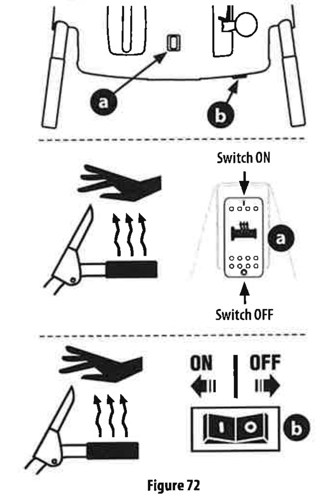
T. HEATED GRIPS (IF EQUIPPED)
CAUTION: It is recommended that you wear gloves when using the heated grip. If the heated grips become too hot, turn them OFF.
To activate the heated grips, move switch found on top (a) or on the rear (b) of dash panel into the ON position (Figure 72). To turnOFF heated grips, move switch to the OFF position.
Starting and Stopping the Engine
WARNING: Always keep hands and feet clear of moving parts. Do not use a pressurized starting fluid. Vapors are flammable.
Refer to the Engine Operator's Manual for instructions on starting and stopping the engine (Figure 73).

TO ENGAGE DRIVE
- With the throttle control in the Fast (rabbit) position, move the shift lever into one of the six forward (F) positions or two reverse (R) positions on 6-speed models or in the desired position on the Hydro models. Select a speed appropriate for the snow conditions and a comfortable pace.
- Squeeze the drive control lever against the handle and the snow blower will move. Release to stop.
TO ENGAGE AUGERS
To engage the augers, squeeze the auger control lever against the left handle. Release to stop.
TO STEER (IF EQUIPPED)
With the drive control lever engaged, squeeze the right steering trigger control to turn right, or squeeze the left steering trigger control to turn left.
CAUTION: Operate the snow blower in open areas and at slow speeds until you are familiar with the drive control and comfortable operating the steering controls.
Clearing a Clogged Chute Assembly
WARNING: Never use your hands to clear a clogged chute assembly. Shut OFF engine, remove safety key or disconnect spark plug wire and remain behind handles until all moving parts have stopped before unclogging.
The chute clean-out tool is conveniently fastened to the rear of the auger housing with a mounting clip. Should snow and ice become lodged in the chute assembly during operation, proceed as follows to safely clear the chute assembly and cute opening:
- Release both the auger control lever and the drive control lever and rotate the chute assembly to the left.
- SHUT THE ENGINE OFF! Remove safety key or disconnect spark plug wire. Refer to the Engine Operator's Manual.
- Remove clean-out tool from the clip which secures it to the rear of the auger housing.
- Use the shovel-shaped end of the clean-out tool to dislodge and scoop any snow and ice which has formed in and near the chute assembly. Always use the clean-out tool (Part#931-2643), not your hands. Refer to the separate supplement for clean-out tool ordering information, if lost or damaged (Figure 74)
- Re-fasten the clean-out tool to the mounting clip on the rear of the auger housing, reinsert the safety key or connect the spark plug wire and start the engine.
- While standing in the operator's position (behind the snowblower),engage the auger control lever for a few seconds to clear any remaining snow and ice from the chute assembly.

Replacing Shear Pins
CAUTION: NEVER replace the auger or central accelerator shear pins with anything other than OEM Part No.738-04124A (round head replacement shear pins), 738-05273 (black colored, round head replacement shear pins) or 738-06654 (hex head replacement shear pins). Any damage to the auger gearbox or other components as a result of failing to do so will NOT be covered by your snow blower's warranty.
WARNING: Shut OFF engine, remove safety key or disconnect spark plug wire prior to replacing shear pins.
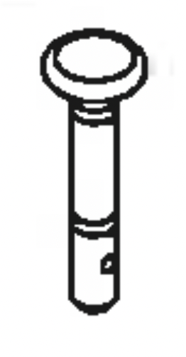
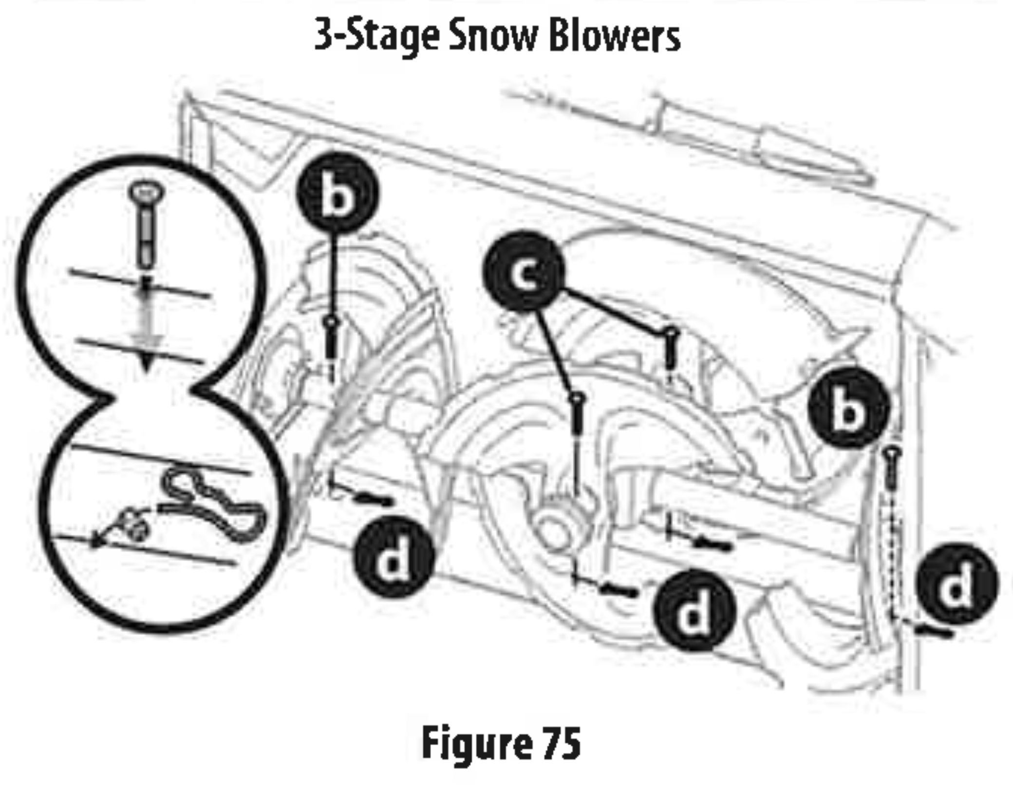
The augers are secured to the spiral shaft with shear pins (a, b or c) and cotter pins (d). If the auger should strike a foreign object or ice jam, the snow blower is designed so that the pins may shear. If the augers will not turn, check to see if the pins have sheared (Figure 75).
IMPORTANT: ALWAYS use the correct OEM replacement shear pin.
2-STAGE SNOW BLOWER REPLACEMENT SHEAR PINS
- The auger is secured to the spiral shaft using roundhead shear pins(a)-OEM Part No.738-04124A.
3-STAGE SNOW BLOWER REPLACEMENT SHEAR PINS
- The side augers are secured to the spiral shaft using black colored, round head shear pins (b) - 0EM part number 738-05273.
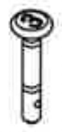
- The central accelerator augers are secured to the spiral shaft using hex head shear pins (c) - 0EM part number738-06654.


SERVICE AND MAINTENANCE
WARNING: Before servicing, repairing or inspecting the snow blower, disengage the auger control lever. Stop the engine, remove the safety key or disconnect spark plug wire to prevent unintended starting.
Troubleshooting
ENGINE
- Engine fails to start, runs erratic, skips(hesitates)or idles poorly. Refer to the Engine Operator's Manual.
Refer to theEngine Operator's Manual for engine related troubleshooting and service.
EXCESSIVE VIBRATION
- Loose or damaged parts.
Stop engine immediately, remove safety key or disconnect spark plug wire. Check for possible damage. Tighten all nuts and bolts. Repair as needed. If the problem persists, contact an authorized service center.
FAILS TO TO PROPEL ITSELF
- Drive control cable in need of adjustment.
Adjust drive control cable.Refer to Drive Control on page 19.
- Drive belt loose or damaged.
Replace drive belt. Contact an authorized Service Center.
- Friction wheel worn.
Replace friction wheel. Refer to Service section on page 28.
FAILS TO DISCHARGE SNOW
- Chute assembly clogged.
Stop engine immediately, remove safety key or disconnect spark plug wire. See Engine Operator's Manual. Clean chute assembly and inside of auger housing with clean-out tool. Refer to Cleaning a Clogged Chute Assembly on page 23.
- Foreign object lodged in auger.
Stop engine immediately, remove safety key or disconnect spark plug wire.See Engine Operator's Manual. Remove object from auger with clean-out tool. Refer to Cleaning a Clogged Chute Assembly on page 23.
- Auger control cable in need of adjustment.
Refer to Auger Control on page 17.
- Auger belt loose or damaged.
Refer to Auger Belt Replacement on page 27.
- Shear pin(s) sheared.
Refer to Replacing Shear Pins on page 24.
CHUTE FAILS TO EASILY ROTATE
- Chute assembled incorrectly.
Disassemble chute control and reassemble as directed in the Assembly & Set-up section.
PUSHES SNOW INSTEAD OF THROWING
- Low/slow ground speed in wet/slushy snow 1-3" in depth.
Increase ground speed and always operate snow blower engine at FULL throttle. Refer to Cleaning a Clogged Chute Assembly on page 23.
- Shear pin(s) sheared.
Refer to Replacing Shear Pins on page 24.
OVERHEAD CHUTE CONTROL DOES NOT STAY STATIONARY WHILE THROWING SNOW.
- Insufficient preload applied to chute control.
Refer to on Overhead Chute Control (If Equipped) on page 17.
Maintenance
ENGINE
Refer to Engine Operator's Manual.
TIRE PRESSURE
Refer to Assembly & Set-up section (page 15) for information regarding tire pressure.
SHAVE PLATE & SKID SHOES
The shave plate and skid shoes on the bottom of the snow blower are subject to wear. They should be checked periodically and replaced when necessary.
NOTE: Deluxe skid shoes (on select models) have two wear edges. When one side wears out, they can be rotated 180° to use the other edge.
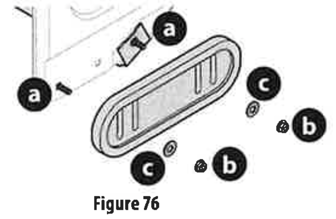
To remove skid shoes (Deluxe shown):
- Remove four carriage bolts(a) and hex flange nuts(b) and flat washers(c) which secure them to the housing.
- Rotate and reassemble new skid shoes with four carriage bolts(a)(two on each side) and hex flange nuts (b) and flat washers(c) (Figure 76).
To remove shave plate:
- Allow the engine to run until it is out of fuel. Do not attempt to drain fuel from the engine.Remove safety key or disconnect spark plug wire.
- Carefully pivot snow blower up and forward so that it rests on the auger housing.
- Remove carriage bolts(a) and hex nuts (b) which attach it to auger housing (Figure 77).
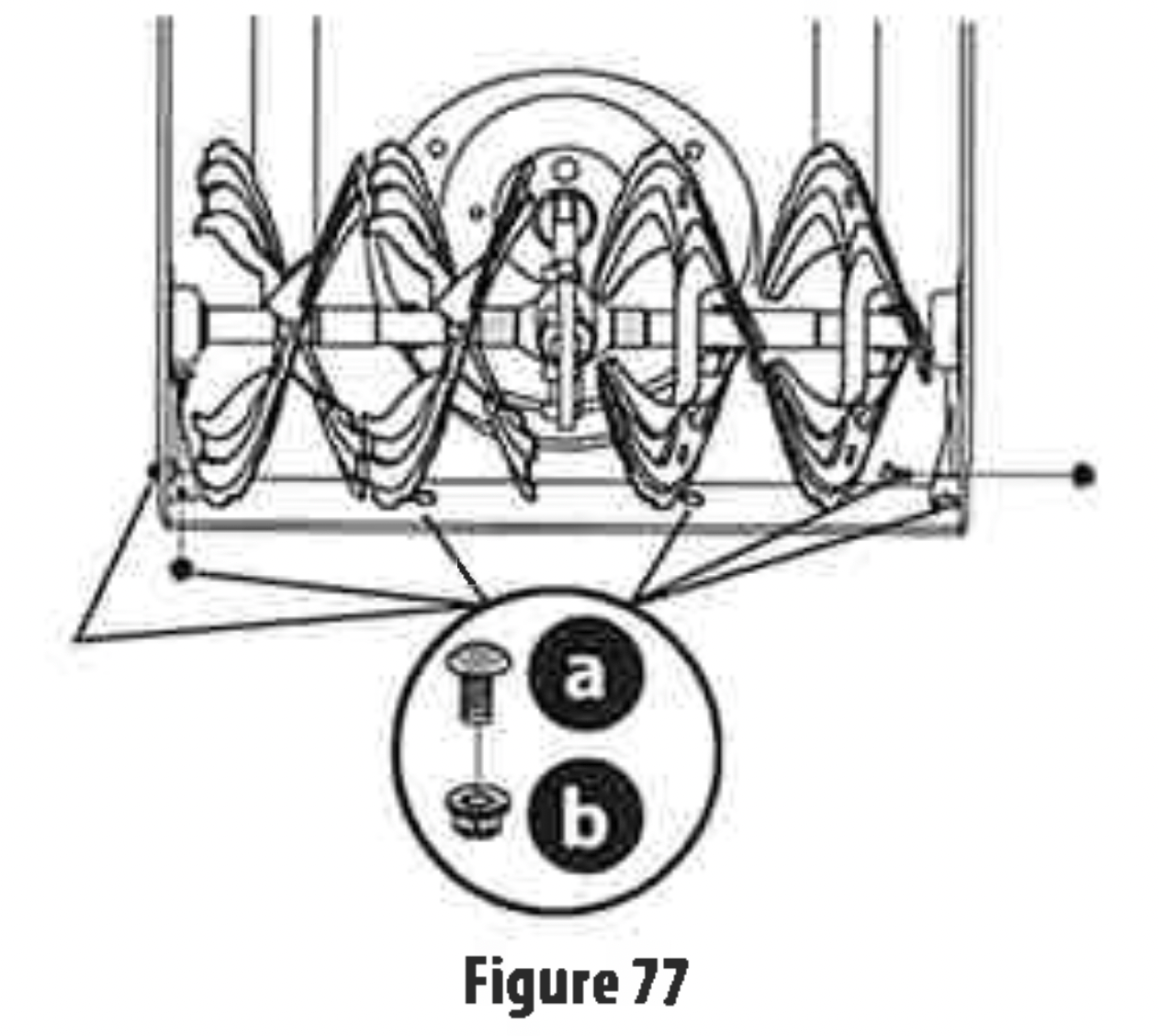
- Reassemble new shave plate, making sure heads of carriage bolts are to the inside of housing. Tighten securely (Figure 77).
- If adjusting the shave plate is necessary, refer to Adjustable Shave Plate (If Equipped) on page 17.
OFF-SEASON STORAGE
If the snow blower will no longer be used until next season, follow the storage instructions below.
- Run engine until fuel tank is empty and it stops due to lack of fuel. Do not attempt to drain fuel from engine.
NOTE: Refer to Engine Operator's Manual for information on storing your engine.
- Lubricate machine as instructed on page 26.
- Store in a clean, dry area.
- If storing in an unventilated area, rustproof machine using alight oil or silicone to coat the snow blower.
- Clean the exterior of the engine and the snow blower.
IMPORTANT: When storing or when it is not being serviced, it is to remain in the upright position with both wheels and auger housing on the ground.
Lubrication
WHEELS
At least once a season, remove both wheels. Clean and coat axles with a multipurpose automotive grease before reinstalling wheels.
SIDE MOUNTED CHUTE ROTATION CONTROL (IF EQUIPPED)
Once a season, lubricate eye-bolt bushing and the spiral with 3-in-1 oil.
NON-HYDRO MODELS (IF EQUIPPED)
The friction wheel hex shaft should be lubricated at least once a season or after every twenty-five (25) hours of operation.
- Allow engine to run until it is out of fuel.Remove safety key or disconnect spark plug wire.
- Carefully pivot snow blower up and forward so that it rests on auger housing.
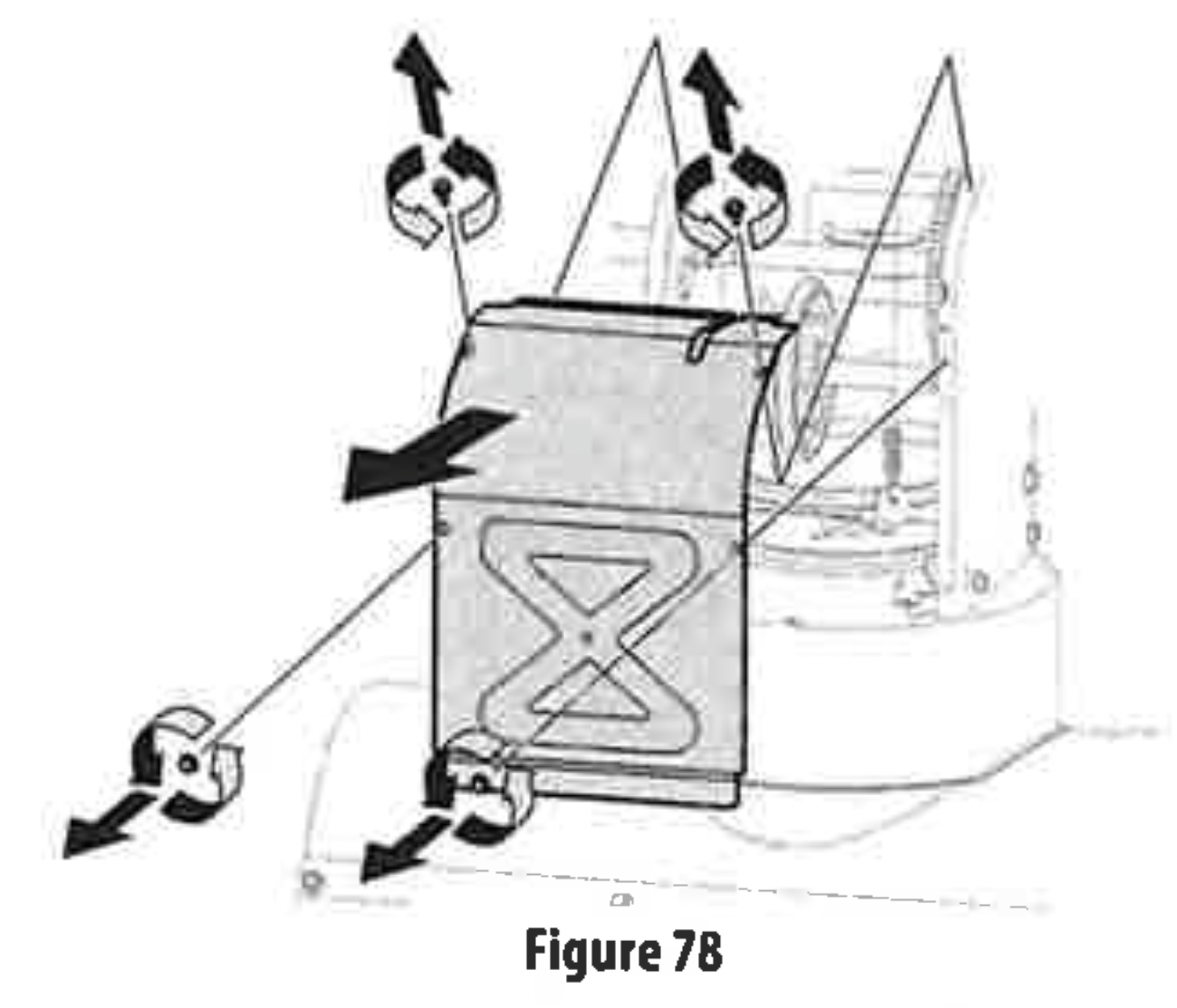
- Remove frame cover from underside by removing self-tapping screws (Figure 78).
- Apply a light coating of Bostik Regular Grade Never-Seez® to hex shaft (Figure 79).
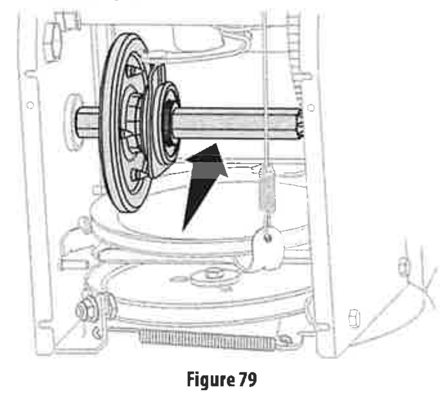
NOTE: When lubricating hex shaft, be careful not to get any lubricant on aluminum drive plate or rubber friction wheel. Doing so will affect the drive system. Wipe off any excess or spilled lubricant.
AUGER SHAFT
At least once a season, remove shear pins (a) and cotter pins(b) from auger shaft(s). Spray lubricant inside shaft and around spacers and flange bearings found at either end of shaft(s) (Figure 80).
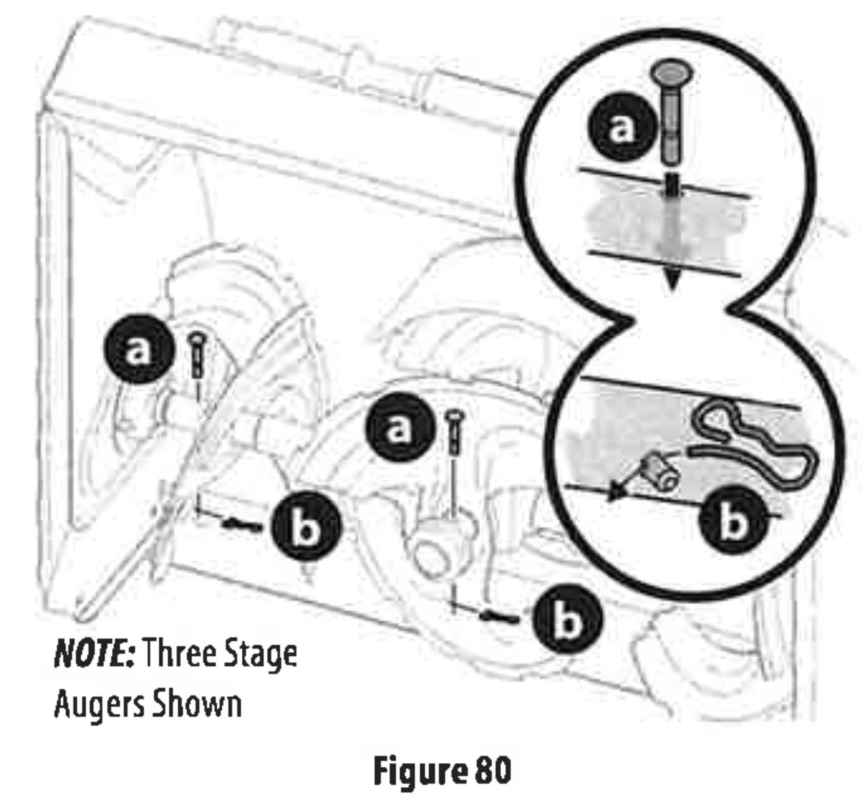
IMPORTANT: On 3-stage models, there is an additional shear pin in the rear accelerator.
Service
AUGER BELT REPLACEMENT
To remove and replace auger belt, proceed as follows:
- Allow engine to run until it is out of fuel. Do not attempt to drain fuel from engine. Remove safety key or disconnect spark plug wire.
- Remove plastic belt cover on front of engine by removing two self-tapping screws(a) (Figure 81).

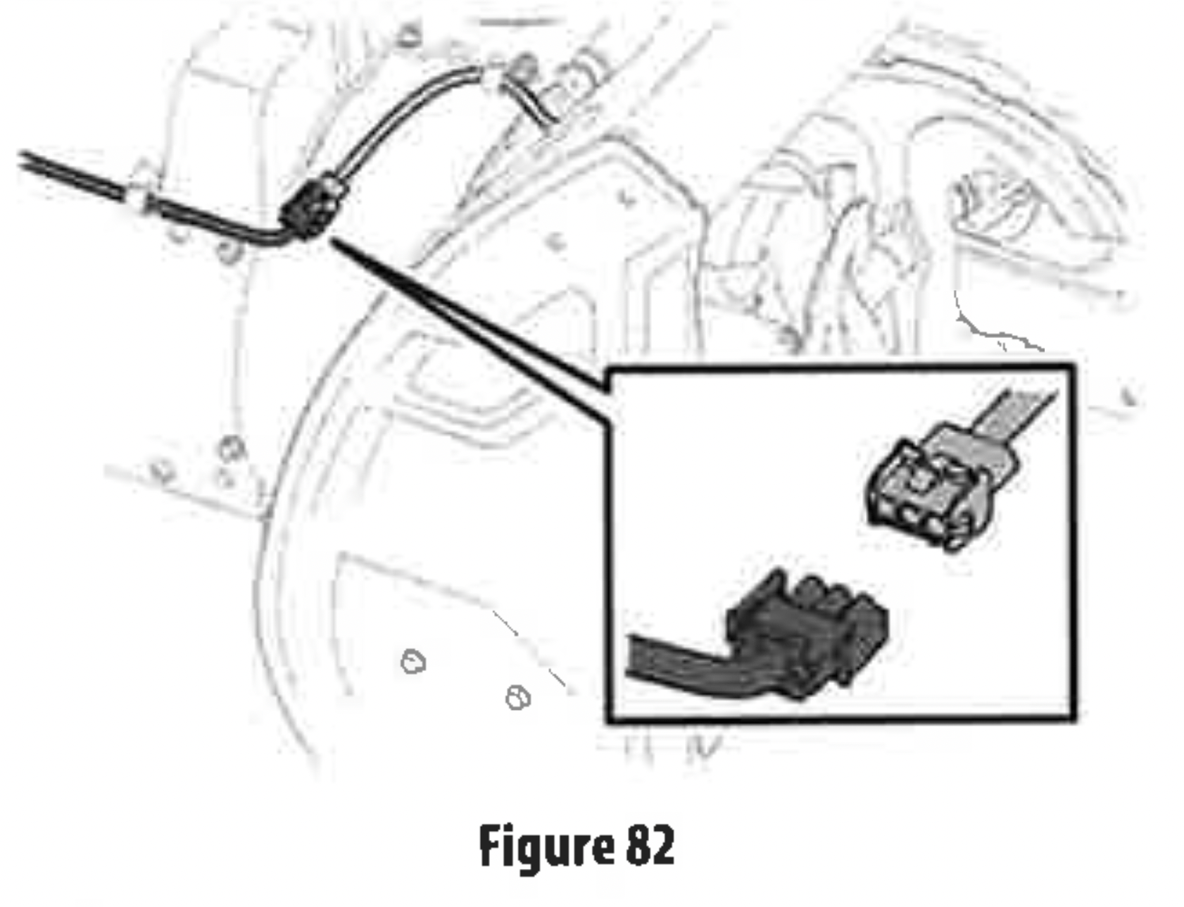
NOTE: On models equipped with the LED light bar on top of the auger housing, make sure to unplug the wire harness before removing the belt cover(Figure 82).
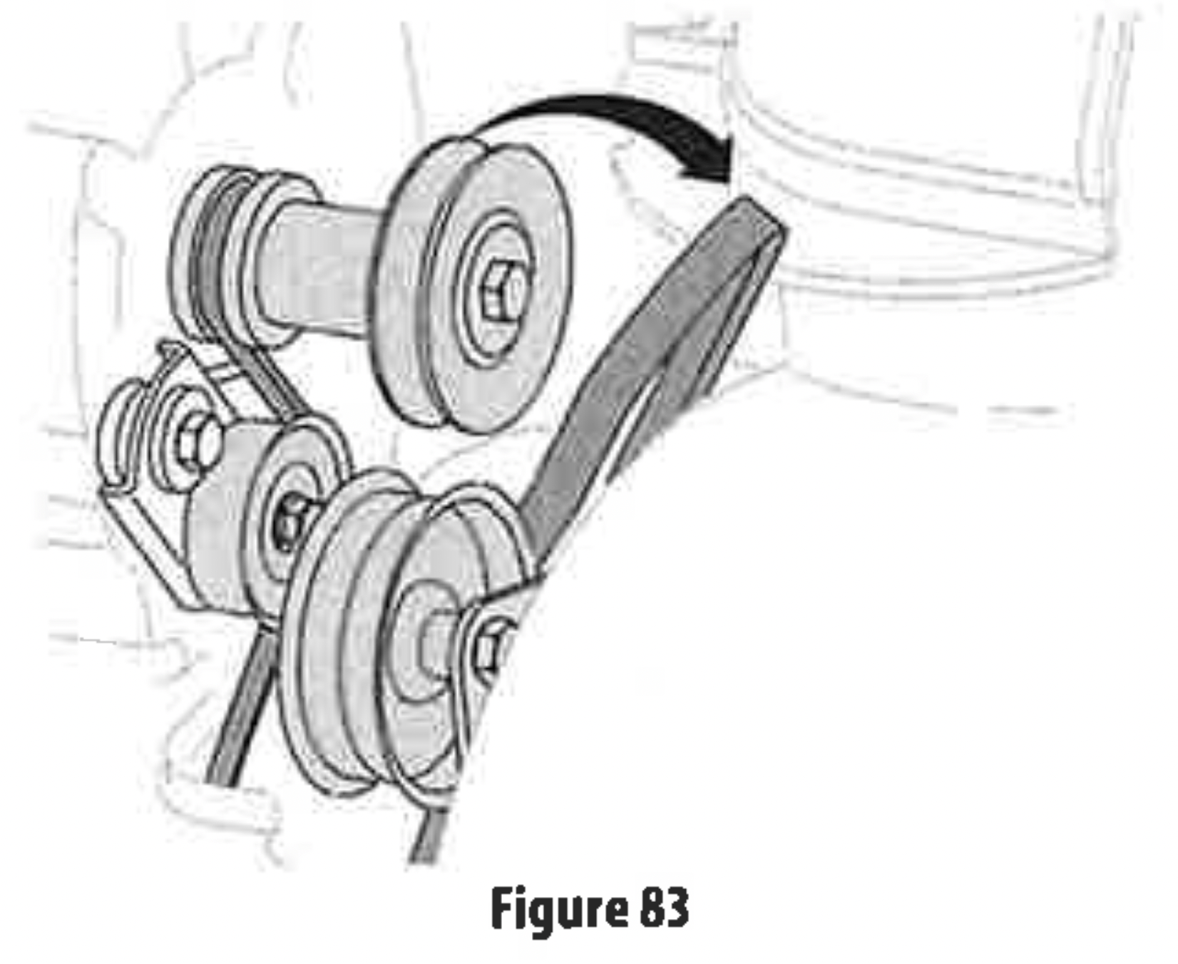
- Roll auger belt off engine pulley (Figure 83).
- Carefully pivot the snow blower up and forward so that it rests on the auger housing.
- Remove frame cover from underside by removing self-tapping screws (Figure 78).
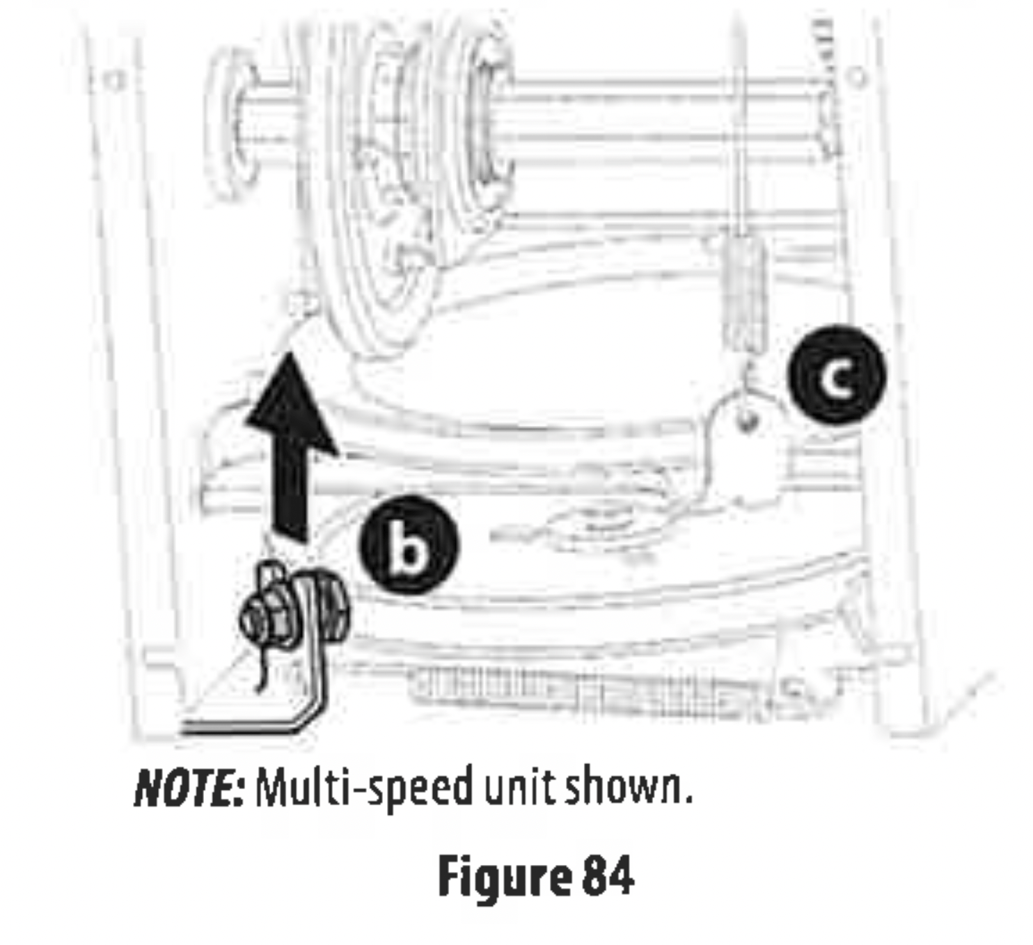
- Loosen and remove shoulder bolt (b) which acts as a belt keeper and unhook the spring (c) from the frame (Figure 84).
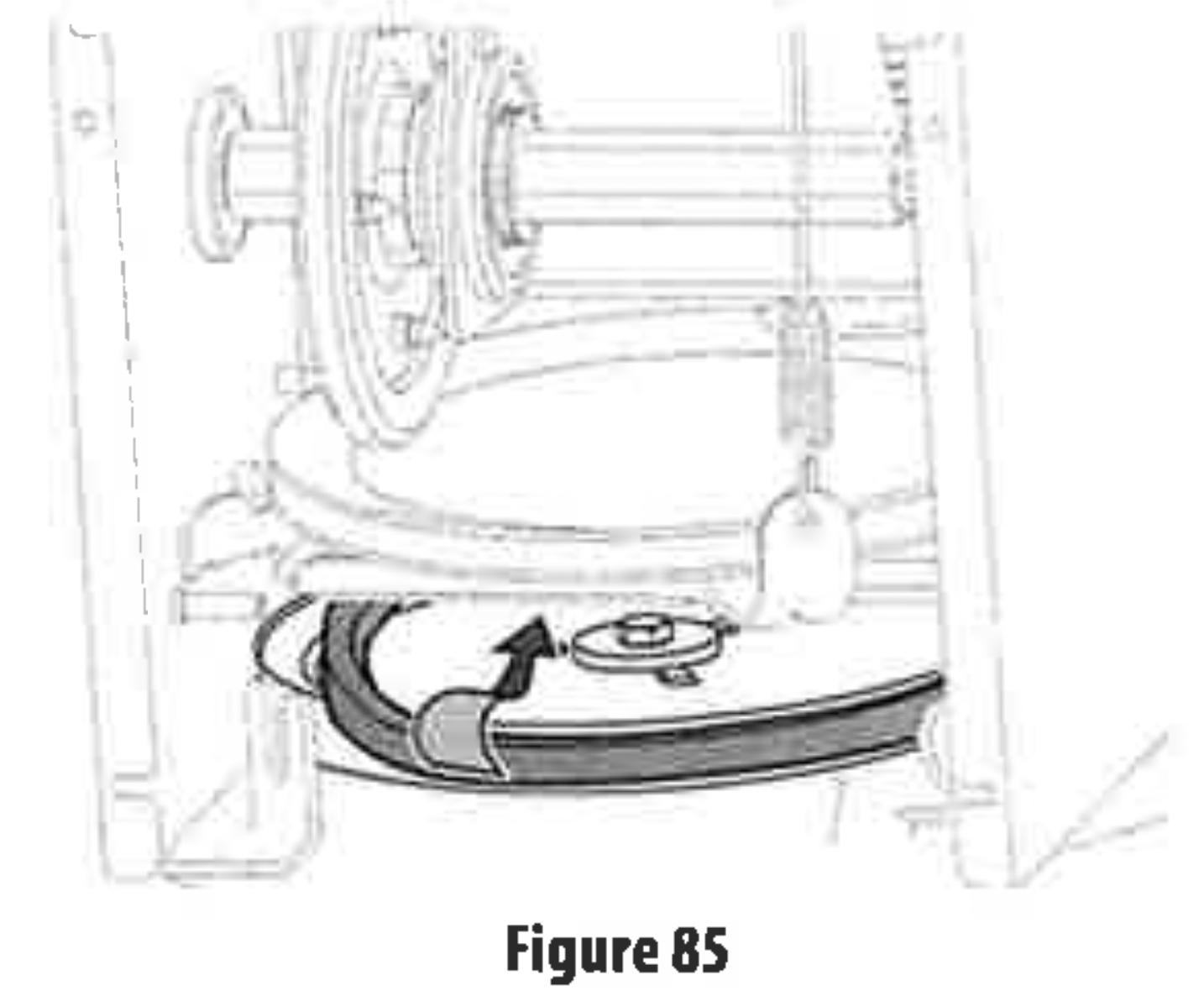
- Remove belt from around auger pulley, and slip it between support bracket and auger pulley (Figure 85).
NOTE: Engaging auger control will ease removal and reinstallation of belt.
- Replace auger belt by following instructions in reverse order.
NOTE: Make sure to reinstall shoulder bolt (a) and reconnect spring to frame after installing a replacement auger belt (Figure 84).
- After replacing auger belt, perform Auger Control test inAssembly & Set-Up section (page 17).
DRIVE BELT REPLACEMENT
NOTE: See your authorized service dealer to have drive belt replaced or contact Customer Support.
FRICTION WHEEL INSPECTION(STEERABLE 500 AND 800 SERIES & NON-STEERABLE SINGLE SPEED 600 SERIES)
If snow blower fails to drive with drive control lever engaged, and performing drive control cable adjustment fails to correct problem, the friction wheel may need to be replaced.
IMPORTANT: Special tools are required and several components must be removed in order to replace the friction wheel rubber. See your authorized service dealer to have friction wheel rubber replaced or contact Customer Support.
To inspect friction wheel, proceed as follows:
- Allow engine to run until it is out of fuel. Do not attempt to drain fuel from engine.Remove safety key or disconnect spark plug wire.
- Carefully pivot snow blower up and forward so that it rests on auger housing.
- Remove frame cover from underside by removing four self-tapping screws (Figure 78).
- Inspect friction wheel for signs of wear or cracking.
- Using the four self tapping screws, reinstall the frame cover (Figure 78).
- If friction wheel rubber must be replaced see your authorized service dealer to have friction wheel rubber replaced or contact Customer Support.
FRICTION WHEEL REMOVAL (MULTI-SPEED NON-STEERABLE 600 SERIES)
If snow blower fails to drive with drive control lever engaged, and performing drive control cable adjustment fails to correct the problem, friction wheel may need to be replaced.Follow the instructions below. Examine friction wheel for signs of wear or cracking and replace if necessary.
- Allow engine to run until it is out of fuel. Do not attempt to drain fuel from engine. Remove safety key or disconnect spark plug wire.
- Place shift lever in first Forward (F1) position.
- Carefully pivot snow blower up and forward so that it rests on auger housing.
- Remove frame cover from underside by removing self-tapping screws (Figure 78). Remove right-hand wheel by removing screw and bell washer which secure it to axle. See (Figure 86).
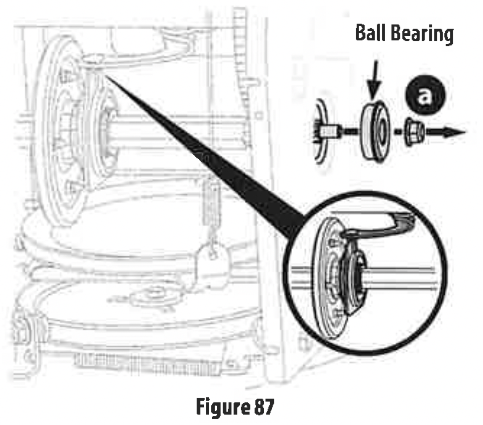
- Carefully remove hex nut (a) which secures hex shaft to frame and lightly tap the shaft's end to dislodge ball bearing from right side of frame (Figure 87).

NOTE: Be careful not to damage threads on shaft.
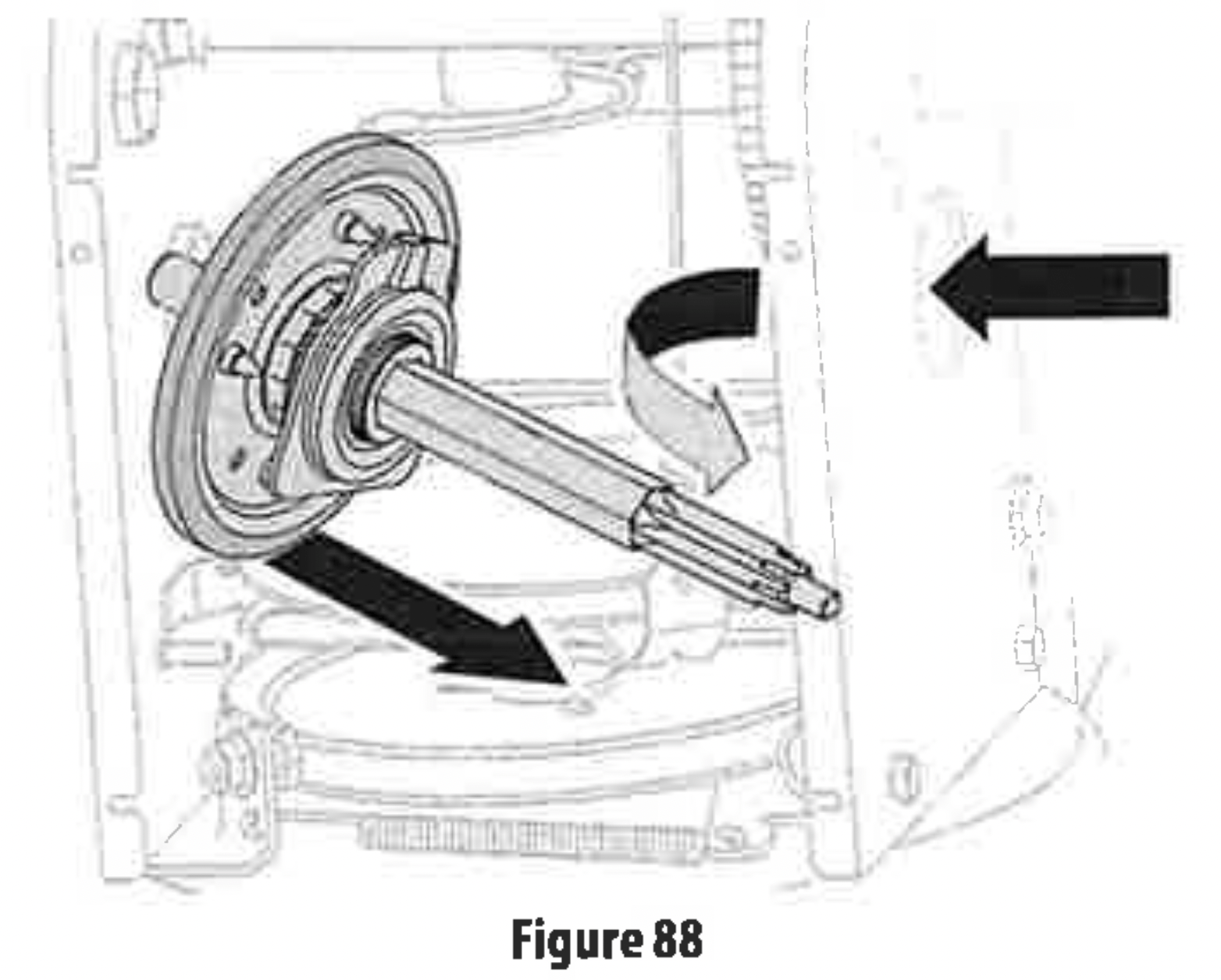
- Carefully position hex shaft downward and to left before carefully sliding friction wheel assembly off shaft (Figure 88).
NOTE: If you're replacing friction wheel assembly as a whole, discard the worn part and slide new part onto hex shaft.
- Follow previous steps in reverse order to reassemble components.
- Perform Drive Control test shown on page 18.
If you're disassembling friction wheel and replacing only rubber ring, proceed as follows:
NOTE: Not all friction wheels are serviceable. If this is the case, simply replace friction wheel assembly.
- Remove four screws(b) which secure friction wheel's side plates together (Figure 89).
- Remove rubber ring from between the plates.
- Reassemble side plates with a new rubber ring.
NOTE: When reassembling friction wheel assembly, make sure that rubber ring is centered and seated properly between the side plates. Tighten each screw only one rotation before turning wheel clockwise and proceeding with next screw. Repeat this process several times to ensure plates are secured with equal force (between 115-145 in-lbs).
- Apply a light coating of Bostik Regular Grade Never-Seez® to hex shaft.
- Slide friction wheel assembly back onto hex shaft and follow the steps above in reverse order to reassemble components.
- After replacing friction wheel, perform Drive Control test shown on page 18.
NOTE: Make sure shift lever pin is in place in bearing housing (Figure 87 inset).
HYDRO TRANSMISSION (IF EQUIPPED)
NOTE: See your authorized service dealer to have the Hydro Transmission serviced or contact Customer Support for assistance and the name of your nearest servicing dealer.