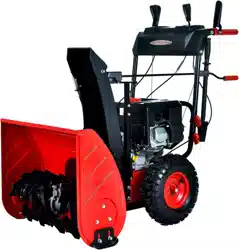
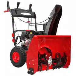
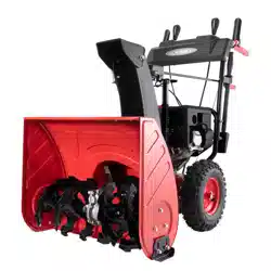
Instructions Manual for PowerSmart PSSHD24 24 inch Two Stage Gas Snow Thrower
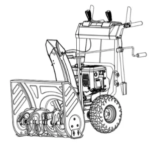
TECHNICAL DATA
24 inch Two Stage Electric Start Snow Thrower
Model #: PSSHD24
Engine: 212cc Snow Engine
Engine oil Capacity: 16 fl.oz
Fuel Tank Capacity: 0.66 Gallon
Start System: 120V Electric / Recoil
Clearing Width: 24 inch
Clearing Height: 20 inch
Chute Rotation Angle: 180o
Speed: 6 Forward, 2 Reverse
Tire Size: 13 inch
Overall Dimensions (L x W x H): 32.3x24.8x22in
Weight: 146.3 lbs
SAFETY INFORMATION
This symbol points out important safety instructions which, if not followed, could endanger the personal safety and or property of yourself and others. Read and follow all instructions in this manual before attempting to operate this machine. Failure to comply with these instructions may result in personal injury.
WARNING! This machine was built to be operated according to the safe operation practices in this manual. As with any type of power equipment, carelessness or error on the part of the operator can result in serious injury. This machine is capable of amputating fingers, hands, toes and feet and throwing foreign objects. Failure to observe the following safety instructions could result in serious injury or even a fatal occurrence.
It is your responsibility to restrict the use of this power machine to persons who read, understand and follow the warnings and instructions in this manual and on the machine.
ROTATING PARTS! Only use clean-out tool to clear blockages. NEVER use your hands.
NEVER direct discharge towards persons or property that may be injured or damaged by thrown objects.
Keep people away from unit while operating. Keep children out of work area and under watchful care of a responsible adult.
TRAINING
Read, understand, and follow all instructions on the machine and in the manual(s) before attempting to
assemble and operate. Keep this manual in a safe place for future and regular reference.
- Be familiar with all controls and their proper operation. Know how to stop the machine and disengage them quickly.
- Never allow children under 14 years of age to operate this machine. Children 14 and over should read and understand the instructions and safe operation practices in this manual and on the machine and be trained and supervised by an adult.
- Never allow “non-trained” adult personnel to operate this machine without proper instruction.
- Thrown objects can cause serious personal injury. Plan and map out your snow-throwing pattern to avoid discharge of material toward roads, bystanders and the like.
- Keep bystanders, pets and children at least 75 feet from the machine while it is in operation. Stop machine if anyone enters the area.
- Exercise caution to avoid slipping or falling, especially when operating in reverse.
PREPARATION
Thoroughly inspect the area where the equipment is to be used. Remove all doormats, newspapers, sleds, boards, wires, branches and other foreign objects, which could be hazardous and damage the auger system.
- Always wear safety glasses or eye shields during operation and while performing an adjustment or repair to protect your eyes, as thrown objects can ricochet and cause serious injury to the eyes.
- Do not operate without wearing adequate, winter outer garments. Do not wear jewelry, long scarves or other loose clothing, which could become entangled in moving parts, and wear footwear that will improve footing on slippery surfaces.
- Use a grounded “three-wire” extension cord and receptacle for all machines with electric start engines.
- Adjust skid shoe and/or housing height to clear gravel or crushed rock surfaces.
- Disengage all control levers before starting the engine.
- Never attempt to make any adjustments while engine is running, except where specifically recommended in the instruction manual.
- Let engine and machine adjust to outdoor temperature before starting to clear snow.
PERSONAL SAFETY
- Engine exhaust, and certain vehicle components contain or emit chemicals known to cause cancer, birth defects or other reproductive harm.
- Read, understand and follow all instructions on your snow thrower unit and in this instruction manual before attempting to assemble and operate your machine. • Keep this instruction manual in a safe place for future and regular reference. If replacement parts are needed, refer to the Panel, Chute, Frame and Housing Diagrams and Parts’ Listings on pages 25-30.
- Stay alert, watch what you are doing and use common sense when operating your snow thrower unit.
- Do not use your snow thrower unit while you are tired or under the influence of drugs, alcohol, medication. A moment of inattention while operating the snow thrower may result in severe bodily injury.
- NEVER LEAVE YOUR RUNNING SNOW THROWER UNATTENDED. Stop the engine!
- Do not leave your snow thrower unit until it has come to a complete stop.
- When stepping backwards, be cautious about any obstacles beneath your feet or behind you avoid falling.
SERVICE
- Stop the engine before making any adjustments. Check for misalignment, breakage or binding of moving parts, and any other conditions that may affect operation.
- If damaged, have the snow thrower unit serviced by an authorized service center using only specified, manufactured replacement parts. This will ensure that the safety of the snow thrower unit is maintained.
SAFE HANDLING OF GASOLINE
To avoid personal injury or property damage use extreme care in handling gasoline. Gasoline is
extremely flammable and the vapors are explosive. Serious personal injury can occur when gasoline is
spilled on yourself or your clothes which can ignite, therefore wash your skin and change clothes
immediately.
- Use only an approved gasoline container.
- Extinguish all cigarettes, cigars, pipes and other sources of ignition.
- Never fuel snow thrower unit's engine indoors.
- Never remove gas cap or add fuel while the engine is hot or running.
- Allow engine to cool at least two minutes before refueling.
- Never over fill fuel tank.
- Replace gasoline cap and tighten securely.
- If gasoline is spilled, wipe it off the engine and equipment. Move machine to another area. Wait 5 minutes before starting the engine.
- Never store the machine or fuel container inside where there is an open flame, spark or pilot light (e.g. furnace, water heats, space heater, clothes dryer etc.).
- Allow machine to cool at least 5 minutes before storing.
- Never fill containers inside a vehicle or on a truck or trailer bed with a plastic liner. Always place containers on the ground away from your vehicle before filling.
- If possible, remove gas-powered equipment from the truck or trailer and refuel it on the ground.
- If this is not possible, then refuel such equipment on a trailer with a portable container, rather than from a gasoline dispenser nozzle.
- Keep the nozzle in contact with the rim of the fuel tank or container opening at all times until fueling is complete. Do not use a nozzle lock open device.
OPERATION
- Do not put hands or feet near rotating parts, in the auger impeller housing or chute assembly. Contact with the rotating parts can amputate hands and feet.
- The auger (impeller) control lever is a safety device. Never bypass its operation. Doing so makes the machine unsafe and may cause personal injury.
- The control levers must operate easily in both directions and automatically return to the disengaged (vertical) position when released.
- Never operate with a missing or damaged chute assembly. Keep all safety devices in place and working.
- Never run an engine indoors or in a poorly ventilated area. Engine exhaust contains carbon monoxide, an odorless and deadly gas.
- Do not operate machine while under the influence of alcohol or drugs.
- Muffler and engine become hot and can cause burning. Do not touch. Keep children away.
- Exercise extreme caution when operating on or crossing gravel surfaces. Stay alert for hidden hazards or traffic.
- Exercise caution when changing direction and while operating on slopes.
- Plan your snow-throwing pattern to avoid snow discharge towards windows, walls, cars etc., thus avoiding possible property damage or personal injury caused by a ricocheting debris.
- Never direct discharge at children, bystanders and pets or allow anyone in front of the machine.
- Do not overload machine capacity by attempting to clear snow at too fast of a rate.... Remember! Slow and steady operation is best to avoid clogs of snow being impelled too rapidly.
- Never operate this machine without good visibility or light. Always be sure of your footing and keep a firm hold on the handles. Walk, never run.
- Disengage power to the auger system (auger/impeller) by releasing the auger control (lever) when transporting or not in use.
- Never operate machine at high transport speeds on slippery surfaces. Look down and behind and use care when backing up.
- If the machine should start to vibrate abnormally, stop the engine, disconnect the spark plug wire and ground it against the engine. Inspect thoroughly for damage. Repair any damage before starting and operating.
- Disengage all (drive and auger) control levers and stop engine before you leave the operation position (behind the handles).
- Wait until the auger /impeller comes to a complete stop before unclogging the chute assembly, making any adjustments or inspections.
- Never put your hand in the discharge or collector openings. Always use the clean-out tool provided to unclog the discharge opening. Do not unclog chute assembly while engine is running. Shut off engine and remain behind handles until all moving parts have stopped before unclogging.
- Use only attachments and accessories approved by the manufacturer (e.g. wheel weights, tire chains, cabs etc.).
- When staring engine, pull cord slowly until resistance is felt, then pull rapidly, Rapid retraction of starter cord (kickback) will pull hand and arm toward engine faster then you can let go. Broken bones, fractures, bruises or sprains could result.
- If situations occur which are not covered in this manual, use care and good judgment contact customer support for assistance.
MAINTENANCE & STORAGE
- Never tamper with safety devices. Check their proper operation regularly. Refer to the maintenance and adjustment sections of manual.
- Before cleaning, repairing, or inspecting machine disengage all control levers and stop the engine.
- Wait until the auger impeller comes to a complete stop. Disconnect the spark plug wire to prevent unintended starting.
- Check bolts and screws for proper tightness (EVERYTIME before & after use) as engine vibration could cause hardware to loosen...consider using a Loc-Tite product to keep hardware secure.
This process will keep the machine in safe working condition. Also, visually inspect machine for any damage.
- Verify that the auger gearbox, located between your right and left auger blades, has substantial lubricant in the casing.
The gearbox fill and drain plugs (bolts) are the only “vertical” plugs (bolts) on the gearbox assembly when viewed in the standing position. The top plug (bolt) is used for filling...the bottom plug (bolt) is for draining. Simply remove the top plug (bolt) for verification of lubricant, as it should be inside. To drain, simply remove bottom plug (bolt).
- Do not change the engine governor setting or overspeed the engine. The governor controls the maximum safe operating speed of the engine.
- Snow thrower auger belts, shave plates, shear pins and skid shoes are subject to wear and damage, therefore it is expected that the owner assume personal responsibility for the maintenance (removal & installation) of these items.
- For your safety protection, frequently check all components and replace with original equipment manufacturers (OEM) parts only. Use of parts which do not meet the original equipment specifications may lead to improper performance and compromise safety.
- Check (drive & auger) control lever (handles) and cables periodically to verify they engage and disengage properly and adjust, if necessary. Refer to the adjustment section in this operator's manual for instructions.
- Maintain or replace safety and instruction labels, as necessary.
- Observe proper disposal laws and regulations for gas, oil, etc. to protect the environment.
- Prior to storing, run machine a few minutes to clear snow from machine and prevent freeze up of auger impeller and completely wipe down unit, while inspecting for frozen components.
- Never store the machine or fuel container inside where there is an open flame, spark or pilot light such as water heater, furnace, clothes dryer etc.
- Always refer to the operator's manual for proper instructions on off-season storage.
- Check fuel line, tank, cap and fittings frequently for cracks or leaks. Replace if necessary.
- Do not crank engine with spark plug removed.
- Have the machine inspected annually by an authorized service dealer to ensure that all mechanical and safety systems are working properly and have not worn excessively*. Failure to do so can result in accidents, injuries or death.
*Please note that an annual inspection is not covered within the warranty program...only REPAIR service.
DO NOT MODIFY THE ENGINE
To avoid serious injury or death, do not modify engine in any way. Tampering with the governor setting can lead to a runaway engine and cause it to operate at unsafe speeds. Never tamper with factory setting of engine governor.
KNOWING YOUR SNOW THROWER
Use the illustrations below to become familiar with the locations and functions of the various components and controls of this snow thrower.
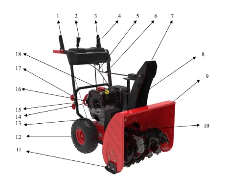
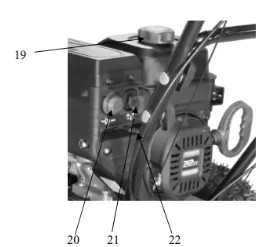
- Drive Control Lever
- Drive Speed/Gear Control
- Chute Deflector Control
- Auger Control Lever
- Chute Rotation Handle
- Clean Out Tool
- Discharge Chute Deflector
- Discharge Chute
- Auger Housing
- Auger Blade
- Skid Shoe
- Wheel Tire
- Belt Cover
- Electric Start Button
- Lower Handle
- Recoil Start Handle
- Handle Knob
- Oil Dipstick
- Fuel Tank Cap
- Primer Bulb
- Switch Key
- Choke Lever
Drive Control Lever
Located on the right side of the upper handle, the Drive Control Handle is used to engage and disengage the drive wheels. Squeeze the Drive Control Handle against the upper handle to engage the wheels; release to disengage.
Drive Speed/Gear Control
The Speed/Gear Control is located on the center of the panel and is used to set the drive speed and
direction of travel. It can be moved into any of eight positions (four forward and two reverse gear settings)
Auger Control Lever
Located on the left side of the upper handle, the Auger Control Handle is used to engage and disengage
the augers. Squeeze the Auger Control Handle to engage the augers; release to disengage the augers.
Chute Rotation Handle
To adjust snow discharge direction, rotate the handle clockwise or counter-clockwise....should rotate 180 degrees.
Skid Shoe
Position the shoes based on the surface conditions. Adjust upward for hard-packed snow. Adjust downward when operating on gravel or crushed rock surfaces.
Auger Blade and Impeller
When engaged, the auger blades rotate to cut snow and direct it into the auger/impeller housing to be
discharged out the chute.
Clean-out Tool
The chute Clean-out Tool is conveniently fastened to the rear of the auger housing with a mounting clip.
It is used to clean the chute assembly and chute opening when snow and ice become lodged.
WARNING! Never use your hands to clear a clogged chute assembly. Shut off engine and remain behind handles until all moving parts have stopped before unclogging.
ASSEMBLY ANDADJUSTMENTS
The following section describes steps necessary to prepare the snow thrower for use. If after reading this section, you are unsure about how to perform any of the steps please call (800) 791-9458 Mon-Fri 9-5 EST for customer service assistance. Failure to perform these steps properly can damage the snow thrower.
Unpacking
Unpack the snow thrower and all its parts, and compare against the list below.
- Snow Thrower
- Discharge Chute Assembly
- Chute Rotation Handle
- (Qty. 2) one set of Skid Shoes with attaching hardware
- (Qty. 4) extra M6 Shear Pins and M6 Locknuts
- Two tires with dowel pins.
- Speed control connection Rod.
- 20oz 5W-30 oil
ASSEMBLY
Your Snow Thrower will require some assembly. Please complete the following steps before using your Snow Thrower.
WARNING: This snow thrower is heavy. Assembly procedures may require lifting equipment utilizing two people.
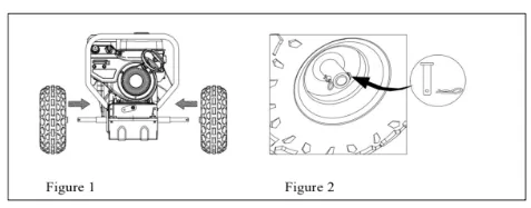
Step 1: Installing the Tire
- Installing left and right tire as indicated on Figure 1. Please move left tire to right if axle move to left when you install right tire.
- Insert bolt and dowel pin as indicated on Figure 2.
Step 2: Installing the Upper Handle
- When installing the Upper Handle, please note that the Drive & Auger Cables will already be pre-attached to Upper Handle.
- Attach Upper Handle using the Frame Handle Assembly Hardware (4 sets /Knob, Saddle Washer, M8 Nut, T-Screw) for your Upper & Lower Handle connection.
- When attaching Assembly Hardware, make sure ALL cables are underneath the Frame (Upper & Lower) Handles after installation as indicated in Figure 3. VERY IMPORTANT!!!***
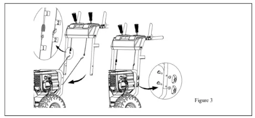
***Assembling Drive & Auger Cables over the top of the Frame
Handle will cause unnecessary tension in the cables, resulting in the Snow
blower propelling forward when starting theengine andmay causedamage to the
drive& augercontrol (levers) when trying to engage them.
- Cut and remove all tie wraps that are on Cables, Frame Handles, Drive Control (Lever) & Auger Control (Lever).
- Verify that the connection for the Upper & Lower Drive/Auger Cables is accurate. (See
Figure 3)
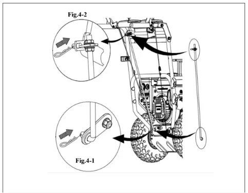
Step 3: Installing Speed Control Connection Rod
- Install the connection rod to the hole in the Frame as indicated on Figure 4 -1.
- Install another side of connection rod to the hole in the trigger as indicated on Figure 4-2.
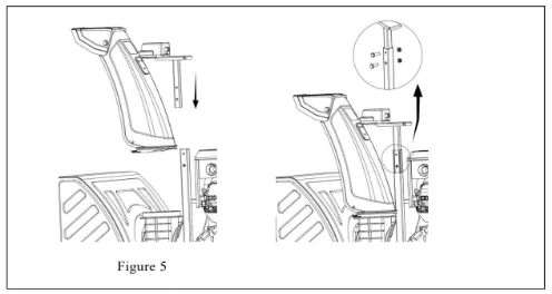
Step 4: Installing The Chute Assembly
- Insert Lower Discharge Chute/Support Tube Assembly into the designated Chute opening for the Lower Discharge Chute, while inserting the Support Tube into the designated base of the Frame. (See Figure 5).
- Secure Support Tube to base with (2) Screws and nuts provided.
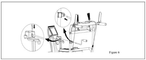
Step 5: Installing the Chute Handle
- Slide Chute Handle through Chute Handle Guide near the Upper Panel, as indicated on Figure 6.
- Attach Chute Handle to base of Chute Gear Connection and secure with Cotter Pin, as indicated on Figure 6.
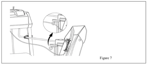
- Verify that ALL cables are clear and not obstructing the Chute Handle operation of your snow thrower unit. Clip the cable into the hook. (See Figure 7)
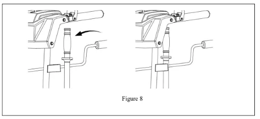
Step 6-Installing Clean Out Tool
- Insert the clean out tool into the lower handle bracket
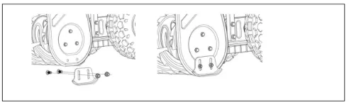
Step 7 – Skid shoes installation and adjustments
- Locate the set of skid shoes from parts bag and remove the bolts.
- Loosely install the skid shoes using the bolts and hex nuts as shown on each side of the auger housing.
Make sure the skid shoe tip faces out.
Adjustment of the skid shoes sets the height above the ground at which the auger shave plate operates.
For clearing snow from concrete, asphalt, and other smooth surfaces, set the auger shave plate so that the bottom of the plate is just above the ground.
For clearing snow from gravel, dirt, and other rough surfaces set the auger shave plate slightly above the ground to avoid dirt and gravel from entering the auger.
The optimal height of the plate will vary depending on the type of surface being cleared. Surfaces with larger gravel or stones require a higher shave plate setting.
- Move the snow thrower to a solid, smooth, and level surface.
- Place a spacer board on the ground underneath the auger shave plate between the skid shoes. The thickness of the board should be the same as the height above the ground you wish to raise the auger shave plate. The skid shoes should not touch the board.
- With the two nuts loose allow the skid shoe to slide to the ground then tighten the nuts to secure the skid shoe.
SNOW THROWER PREPARATION
ADD OIL
The snow thrower is shipped without oil. User must add the proper amount of oil before operating the
snow blower for the first time. The oil capacity of the engine crankcase is 16 fl. oz. For general use, we
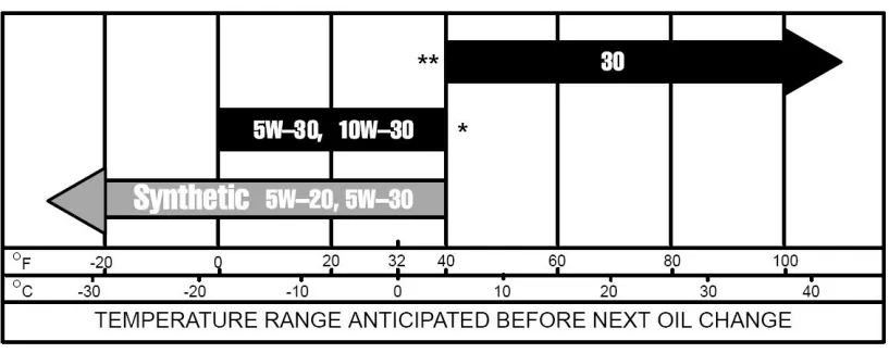
recommend 5W-30, 4-stroke engine oil.
ENGINE OIL RECOMMENDATIONS
Select good quality detergent oil bearing the American Petroleum Institute (API) service classifications
SJ, SL, or SM (synthetic oils may be used). Use the ASE viscosity grade of oil from the following chart
that matches the starting temperature anticipated before the next oil changes.
To add oil, follow these steps:
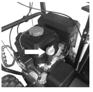
- Make sure the snow thrower is on a level surface. Tilting the snow thrower to assist in filling will cause oil to flow into engine areas and will cause damage. Keep snow thrower level!
- Remove the dipstick from the engine.
- Add oil slowly as to not overflow the unit.
- To check the oil level, wipe the dipstick with a clean rag. Insert the dipstick into the oil fill opening without screwing it in. Remove the dipstick to check the oil mark.
- Slowly add more oil and repeat step 4 until the oil mark reaches to the top of the dipstick. Do not overfill the crankcase.
- Check for oil leaks. Tighten dipstick firmly.
ADD GASOLINE
Use fresh (within 30 days from purchase), lead-free gasoline with a minimum of 87 octane rating. Do not
mix oil with gasoline.
To add gasoline, follow these steps:
- Make sure the snow thrower is on a level surface.
- Unscrew fuel tank cap and set aside. NOTE: The fuel cap may be tight and hard to unscrew.
- Slowly add unleaded gasoline to the fuel tank. Be careful not to overfill. The capacity of the fuel tank is 0.66 gallons. NOTE: Do not fill the fuel tank to the very top. Gasoline will expand and spill over during use even with the fuel cap in place.
- Reinstall fuel cap and wipe clean any spilled gasoline with a dry cloth.
IMPORTANT:
- Never use an oil/gasoline mixture.
- Never use old gasoline.
- Avoid getting dirt or water into the fuel tank.
- Gasoline can age in the tank and make starting difficult. Never store snow thrower for extended periods of time with fuel in the tank or the carburetor.
- NOTE: After completing the above preparation, the engine is ready to be started.
WARNING! Keep the area of operation free from foreign objects that can be thrown by the auger and/or impeller blades. Perform a thorough inspection of the area since some objects may be hidden from view by surrounding snow. If the snow thrower hits an obstruction or picks up a foreign object during use, stop the snow thrower immediately, remove the obstruction, and inspect it for damage. Repair or replace any damaged parts before restarting and operating you snow thrower.
- Keep children, pets, and bystanders away from the area of operation. Be aware that the normal noise of the snow thrower when turned on may make it difficult for you to hear approaching people.
- Start your clearing path by throwing snow in a back and forth motion. To clear in the opposite direction, stop your snow thrower and pivot it on its’ wheels to face the opposite direction. Make sure to overlap clearing paths.
- Determine the direction of the wind. If possible, move in the same direction as the wind so that the snow is not thrown against the wind, back into your face and on the just cleared path.
WARNING! DO NOT USE YOUR HANDS TO UNCLOG CHUTE. Stop the motor before removing debris. Use the supplied Clean-out tool to unclog the chute. Do not walk in front of your running snow thrower. Do not direct discharged snow towards bystanders.
- Do not apply additional man-made load to the engine since this may damage the engine.
- Some parts of your snow thrower may freeze under extreme temperature conditions. Do not attempt to operate your snow thrower with frozen parts. If the parts freeze while your snow thrower is in use, stop the unit and inspect it for frozen parts. Thaw all parts before restarting and operating your snow thrower. Never force parts or controls that are frozen. Never use an open flame of any sort to thaw frozen parts.
Pre-Operation Inspection - IMPORTANT!!!
Before using your snow thrower for the first time, check the following:
- Have you read and followed all setup and operation procedures for the engine as outlined?
- Has the engine been filled with oil and gasoline to the proper level?
- Are all snow thrower components properly attached and assembled?
- Are there any broken or damaged parts?
- Are all fasteners tight?
- Are the tires inflated to the proper pressure?
NOTICE: If you are unsure about the assembly or condition of any of your snow thrower parts, please
call our customer service department at (800)791 9458.
AUGER AND DRIVE CONTROLS
- To engage the auger (blades), press down on the auger control lever (left side handle).
- To engage the drive, press down on the drive control lever (right side handle). The machine should start moving in the direction and speed for the respective setting on the speed/gear control.
- When finished clearing a snow path, release the auger control lever (handle) and the drive control lever (handle).
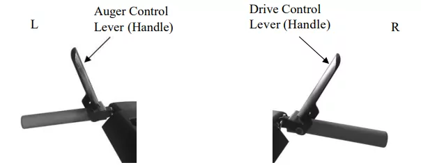
Attention: Release (disengage) the auger and drive control lever (handles) before adjusting the drive speed control lever. NEVER change the drive/gear speed while your snow thrower is in motion, as it will damage the drive mechanism and void the warranty.
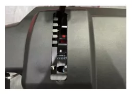
DRIVE SPEED/GEAR CONTROL
Move the drive speed control lever to the desired speed. There are eight (8) settings: six (6) forward speeds and two (2) reverse speeds. 1 is the slowest forward speed and 6 is the fastest forward speed. R1 is the slowest reverse speed and R2 is the fastest reverse speed.
Note: There is no neutral drive setting since the drive control handle must be engaged for movement. Neutral is achieved when the drive control handle is disengaged.
CHUTE DISCHARGE DIRECTION ADJUSTMENT
WARNING - Never direct the snow discharge chute at the operator, bystanders, vehicles or nearby windows. Discharged snow and foreign objects accidentally picked up by the Snow Thrower can cause serious damage and severe bodily injury. Always point the discharge chute in the opposite direction from potential hazards. The discharge chute can be adjusted 180o by rotating the chute rotation handle. Rotate the chute rotation handle clockwise to move the discharge chute to the left; counterclockwise to move the chute to the right.
OPERATING YOUR SNOW THROWER
MANUAL START THE ENGINE
To manual start the engine, perform the following steps:
- Check the oil and fuel levels.
- Move the choke lever to the “CLOSE” position.
- Make sure insert the switch key.
- Press the primer bulb 3 times.
- Pull on the recoil starter handle slowly until a slight resistance is felt, then pull quickly to start the engine. Return cord gently into the recoil starter. Never allow the cord to snap back.
- If engine fails to start, repeat step 4. NOTE: After repeated failed attempts to start the engine, please consult the troubleshooting guide before attempting again. If problems persist, please call customer service.
- Once the engine has started, slowly return the choke lever all the way to the “OPEN” position.
- Allow the engine to run for several minutes before cleaning snow. This allows the engine to stabilize its speed and temperature.
ELECTRIC START THE ENGINE
To start the engine using the electric start function, perform the following steps:
- Check the oil and gas levels.
- Move the choke lever to the “CLOSE” position.
- Make sure insert the switch key.
- Press the primer bulb 3 times.
- Plug the power cord to starting motor.
- Press the start button for 2-3 seconds or until the engine starts. NOTE: If the engine does not start after 2-3 seconds, release the start button.
- If engine fails to start, wait 10 seconds, then repeat step 6. NOTE: After repeated attempts to start the engine, please consult the troubleshooting guide before attempting again. If problems persist please call customer service.
- Once the engine has started. Slowly move the choke lever all the way to the “OPEN” position. Allow the engine to run for several minutes before attempting to clean snow.
CLEARING SNOW
Start the engine once your snow thrower has been running outside for several minutes, it is now ready for use. Make sure the path in front of your Snow Thrower is free from people, animals, objects, and all other obstructions except for snow.
Adjust the chute outlet to the desired direction.
Turn the chute rotation handle clockwise or counter-clockwise until the desired position is reached.
WARNING! Never direct the chute outlet toward people or animals. While snow may seem harmless, it
can contain rocks or other debris that can cause serious injury when projected through the chute.
- Engage/depress the auger control lever (handle) to start the augers and impeller turning.
- Set the desired direction and speed using the speed/gear control lever.
- Engage/depress the drive control lever (handle) and direct the snow thrower into the snow to be cleared.
NOTICE: NEVER change speed/gear positions while the drive control lever (handle) is engaged.
Disengage the drive control handle BEFORE changing speeds or directions. If the snow is deeper than the height of the auger, remove it in several steps taking narrower swaths. Make several passes with the auger overlapping the cleared areas and reduce forward speed.
For the best clearing efficiency, clear snow before it melts, refreezes and hardens. Hard packed and wet snow can be very difficult to clear.
Clearing wet heavy snow can be a challenge, depending on ambient temperature, humidity levels, and overall climate conditions including actual snow conditions, there may be no 100% solution as snow may be too wet or compacted to move or throw. Wet snow will tend to clog and stick more to the augers and chute. Keep the auger engaged as much as possible when clearing wet snow to help prevent clogging.
WARNING! If snow is filled with foreign material, damage to the snow thrower may result. Avoid
snow with foreign materials.
STOPPING
When finished using your snow thrower, perform the following steps to shut it down.
- Engage the auger and impeller for 30 seconds to clear any remaining snow inside your snow thrower.
- Stop the auger blade rotation by releasing the (left) auger control lever (handle).
- Remove Engine Safety Switch Key to stop engine operation.
- Remove snow from all snow thrower surfaces including the auger housing and chute areas.
CLEARING RESTRICTIONS
If the snow discharge chute or auger housing becomes clogged STOP the engine,Remove the Engine Safety key and make sure that all rotating parts have come to a complete stop. Use the supplied snow clean out tool to clear the obstruction. After unclogging, wipe the tool clean, and place it in the holder on top of the auger housing.
MAINTENANCE
WARNING! Never perform maintenance while your snow thrower is running. Turn OFF the engine by removing the switch key before performing any maintenance tasks on,your Snow Thrower.
Proper maintenance of your snow thrower will help prolong its life. Please perform the following maintenance procedures as required.
Do not attempt to repair your snow thrower unless you have the proper tools and instructions for disassembly and repair.
Check the bolts at frequent intervals for proper tightness to ensure that the equipment is in safe working condition.
After each snow removal session, run the snow thrower for a few minutes to prevent the auger/impeller system from freezing. Stop the engine, wait for all revolving parts to stop completely, and wipe residual ice and snow off the unit. Rotate the chute rotation handle several times to remove any excess snow.
MAINTENANCE PROCEDURES
TIRE INFLATION
Before each use of your Snow Thrower, check the tire pressure. The pressure in each tire should be in the range of 20-24 psi for the best performance. The pressure can be checked using an ordinary tire pressure gauge. Fill the tires using a small or pressure regulated air compressor.
WARNING! DO NOT OVER-INFLATE THE TIRES. Over-inflating could cause a tire to burst and cause severe bodily injury.
SHAVE PLATE REPLACEMENT
Remove both skid shoes and hardware including carriage bolts and nuts which attach shave plate to snow thrower housing. Reassemble new shave plate, making sure heads of the carriage bolts are to the inside of the auger housing.
AUGER OR IMPELLER JAMS
WARNING! The auger and impeller rotate at fast speeds which can cause harm or even amputation to a person's body parts. Even if you do not see the auger or impeller rotating, it may start at any time if the engine is running.Remove the Safety Key before cleaning the jams.The chute clean-out tool is fastened to the upper tube with mounting clips.
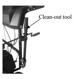
- Always turn OFF the engine before attempting to clear any clogs or jams.
- Keep hands and feet away from rotating parts while the engine is running.
- Do not wear loose fitting clothing that can become entangled in rotating parts.
- Wait until the auger and impeller have come to a full stop.
- Clear any visible jams using the clean out tool attached to your machine.
WARNING! DO NOT try to clear jams with your hands or feet.
AUGER SHEAR PINS REPLACEMENT
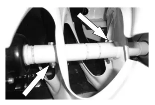
Shear pins are used to attach the auger shaft to the auger blades. Stop the engine by removing the safety key. A clog or jam in the augers may cause one or multiple shear pins to break.
The shear pins are a safety mechanism and designed to break under high load or impact and protect the auger drive system from damage.
Replacement shear pins and nylon locknuts are provided with your snow thrower.
For additional replacement shear pins, please call the customer service department at (800)791 9458.
- Turn off the engine and wait for all moving parts to come to a complete stop. Remove any remnants of the broken shear pin. It may be necessary to unscrew the nut from the broken shear pin and drive out the broken pin.
- Insert a new shear pin through the hole in the auger shaft and tighten using the shear pin nylon locknut. Do not over-tighten the nylon locknut.
NOTICE: Never replace the shear pins with standard pins or fasteners. Damage may occur to the snow
blower and drive systems.
DRIVE SPEED CONTROL ADJUSTMENT
The speed/gear control lever is connected to connection rod that work in tandem to control machine speed and direction.
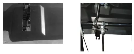
Depending on if the connection rod setting towards forward or reverse, adjustment of the connection rod
will vary.
To adjust the connection rod, two nuts should be moved up and down until there is a positive direction change when the lever is shifted between F1 and R1. The middle position between these two settings is neutral (there is no actual neutral "notched" position on the control panel).
- With the engine running engage the drive control handle and move the speed control lever between 1 and R1 to determine which way the connection rod need to be adjusted. Release the drive control handle when shifting between gears.
- Loosen the jam nuts on connection rod (only one or two threads) and move upper and down nuts as required until a positive direction change is achieved when the lever is shifted between F1 and R1. This may take multiple attempts to find the exact setting.
- Tighten the cable jam nuts once the proper setting has been achieved.
AUGER BELT REMOVAL
WARNING! Entanglement Hazard – Before performing any service procedures, make sure the engine is
off and remove the spark plug wire from the spark plug to ensure the engine cannot accidently start.
Note: Record component position before disassembly, to assist in reassembly.
- Disconnect the upper cable from the auger control handle.
- Remove (Qty. 2) hex screws and remove belt cover.
- Loosen the belt guide pin hex screw (installed on engine crankcase) and rotate the pin away from the pulley.
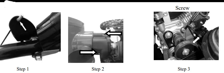
- Left Side - Loosen the hex nuts attaching the auger housing to the main frame.
- Right Side - Remove the hex nuts, lock washers and flat washers attaching the auger housing to the main frame.
- Remove the belt from the drive pulley while pulling the right side of the auger housing away from the main frame just enough to access the belt and auger pulley.
- Push the auger tension pulley arm to move the auger brake, away from the belt to allow removal of the belt.
- Remove the auger belt.
AUGER BELT INSTALLATION
WARNING! Entanglement Hazard – Before performing any service procedures, make sure the engine is
off and remove the spark plug wire from the spark plug to ensure the engine cannot accidently start.
- Push the auger tension pulley arm to move the auger brake to allow access for installation of the belt into the auger pulley.
- Route the belt to the inside of the tension pulley, auger brake and install the auger belt onto the drive pulley while pulling the auger housing into position with the main frame.
- Install and/or tighten the hex nuts attaching the auger housing to the main frame. Tighten all fasteners securely, do not over tighten.
- With the belt installed on both pulleys and tension pulley in position, move the belt guide pin to within 3/16 to 3/8 in. from the belt seated in the pulley and tighten the pin in position.
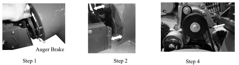
Note: The belt guide pin helps keep the belt in the pulley when the belt is disengaged. The pin should not be tight to the belt. The pin should be loose enough to allow the belt to spin freely but not allow the belt to jump off the pulley.
- Connect the upper cable to the auger control handle.
- Install belt cover using (Qty. 2) hex screws.
WARNING! Ensure the belt cover is installed and all safety guards are in place before the engine is
started and at all times when the engine or machine are operating.
AUGER BELT AND RELATED COMPONENT INSPECTION
When replacing your snow blower auger belt, it is important to determine the cause of the failure (if
applicable) and take corrective action to avoid repeated failure.
Inspect the belt:
- Correct size and type
- Fraying or peeling apart
- Missing pieces
- Cracks and tears
- • Burning
- Uneven wear patterns
- General damage
- Foreign material on belt, oil, grease, dirt etc.
Inspect the auger pulleys:
- Broken sheave or hub
- Loose or missing mounting bolts
- Bent or "out-of-round" condition (pulley doesn’t spin true)
- Misaligned pulleys
- Foreign material on pulleys, oil, grease, dirt, etc.
- Misaligned tension pulley
- Tension pulley loose or damaged
- Tension pulley and arm assembly operation
- Does the tension arm move freely both engaged and disengaged directions without binding?
- Misaligned tension pulley, the pulley should move parallel to the belt centered to the belt
- Check return spring operation and tension
Inspect the auger control lever (handle) and cable:
- Cable and connection damage
- Free movement (from engage to disengaged positions) • Binding or improperly routed cable
- Cable pulley(s) damage, misalignment and binding
- Cable adjustment plate damaged or improper installation
- Handle damaged or binding at pivot
STORAGE & CLEANING
PROPER STORAGE PROCEDURES
WARNING! Never store your snow shrower for extended periods of time with fuel in the tank or
carburetor. Fuel stabilizer can be added to the fuel in can to extend its shelf life for storage.
Store the unit in a locked, dry place out of the reach of children to prevent unauthorized use or damage.
Cover loosely with a tarp for added protection.
CLEANING
- To clean your Snow Thrower, use a damp cloth and mild detergent on the surfaces only. Never get soap or water inside the working mechanisms of your Snow Thrower.
Note: Do not clean with water. Water will freeze due to low temperature and damage the machine.
- Clean the Snow Thrower of snow and ice buildup before storing or transporting. Be sure to secure the unit while transporting.
- Inspect the Snow Thrower carefully for worn, loose, or damaged parts. Check connections and screws and tighten if necessary.
SPARK PLUG SERVICE
Recommended spark plugs: F7RTC or other equivalents.
NOTICE: An incorrect spark plug can cause engine damage.
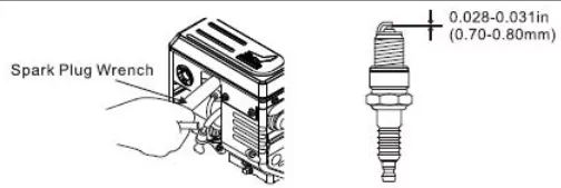
- Disconnect the spark plug cap, and remove any dirt from around the spark plug area.
- Remove the spark plug with a spark plug wrench.
- Inspect the spark plug. Replace it if the electrodes are worn, or if the insulator is cracked or chipped.
- Measure the spark plug electrode gap with a suitable gauge. The gap should be 0.028–0.031 in (0.70–0.80 mm). Correct the gap, if necessary, by carefully bending the side electrode.
TROUBLESHOOTING
WARNING - Before attempting to make any inspections, repairs or adjustments, stop the engine, wait for all moving parts to stop moving and carefully disconnect the engine spark plug wire. If tipping or turning the snow blower is required for any inspection or repair, first wait until the engine is cool to the touch and then drain the engine of all fuel and oil into suitable containers and store or dispose of in a proper manner.
| Problem |
Causes |
Remedy |
|
Engine Systems - Note: For all engine problems, see the below troubleshooting information.
|
| Engine Fails to Start (Engine cranks over) |
Spark plug wire disconnected |
Connect wire to spark plug |
| Faulty spark plug |
Clean, adjust gap, or replace spark plug. |
| Engine flooded with fuel |
Discontinue choke or primer use, clean or replace spark plug. |
| Safety key not inserted in engine ignition |
Insert key fully into the switch |
| Choke not in START position |
Move choke to START position, after engine starts slowly move to RUN position as engine speed and operation stabilizes at the set rpm. If engine still does not start move to half choke and crank engine. |
| Fuel incorrect, old or stale, will not ignite |
Empty and clean fuel tank & carburetor, refill with fresh, clean gasoline. (Note: Fuel may become stale after 30 days in some cases) |
| Blocked or clogged fuel system or line |
Clean fuel system or line |
|
Extension cord is not properly attached to electric starter terminal
|
Re-insert extension cord into electric starter terminal. |
| Extension cord is not properly attached to electric starter terminal |
No power from power supply, tripped breaker
|
Check power supply extension cord is attached to. |
| Extension cord wire gauge is too small or cord is too long |
Use proper rated and length extension cord |
| CHOKE in ON or partial ON position |
Move CHOKE lever to RUN |
| Engine runs erratic, stalls or seems low on power |
Fuel incorrect, old or stale |
Empty and clean fuel tank & carburetor, refill with fresh, clean gasoline. (Note: Fuel may become stale after 30 days in some cases) |
| Blocked or clogged fuel system or line |
Clean fuel system or line |
| Carburetor is in need of cleaning |
Clean fuel system and carburetor |
| Spark plug wire loose |
Connect and tighten spark plug wire |
| Faulty spark plug |
Clean, adjust gap, or replace spark plug, see Engine Operator's manual |
| Engine oil over filled |
Drain oil to proper level. Oil should not be above the top 2 threads of LOWER fill plug. |
| Engine oil level low or empty |
Add oil |
| Drive system |
| No forward or reverse drive movement when drive handle engaged |
Drive belt loose or damaged |
Check drive belt tension pulley for damage or incorrect tension, repair as necessary. Replace drive belt. |
| Friction drive wheel is worn or damaged |
Replace friction drive wheel |
| Friction drive wheel wet or slipping |
Allow snow blower to dry and or warm up or adjust drive cable tension as necessary |
| Wheel to axle pins broken or missing |
Replace pins attaching wheels to axle |
| Drive speed control stuck in gear or won’t change gears |
Speed control lever loose or damaged, not moving speed control cables |
Check speed control lever and cables for damage or loose or missing parts. Repair or replace parts as needed, ensure pivot stud spring tension is correct, adjust pivot nut spring tension as needed. |
| Speed control cables loose, damaged or binding |
Repair, adjust or replace as necessary |
| Drive speed control allows only 1 direction |
Speed control cables misadjusted, loose, damaged or binding
|
Check speed control lever and cables for damage or loose or missing parts. Repair or replace parts as needed. Adjust drive speed control cables, see Drive Speed Control Cables Adjustment |
| Drive engaged when drive control handle released |
Drive control cable binding, won’t release |
Repair, replace cable as necessary |
| Friction drive wheel return spring broke or missing |
Replace spring, adjust cable as necessary |
| Auger system |
|
Auger not rotating when auger control handle engaged or Not blowing snow or Poor snow blowing performance
|
Chute assembly clogged |
Clean chute and inside of auger housing with clean-out tool |
| Auger shear pins broken |
Replace shear pins. Check each auger blade shear pin.
|
| Foreign object in auger or impeller causing auger to stop without shearing pins |
Remove object from auger or impeller areas |
| Auger belt loose, slipping, worn or damaged |
Replace auger belt |
| Auger belt tension cable loose, damaged or binding |
Repair, adjust or replace as necessary |
| Auger blade(s) damaged or bent |
Replace auger blade(s) |
| Auger gearbox mechanical damage, auger drive system not rotating freely (binding) |
Check bearings, bushings and all system parts for damage or mechanical binding. Repair or replace as necessary using proper lubrication
|
| Impeller damaged |
Replace impeller |
| Impeller not connected to impeller shaft, impeller or shear pins broken |
Replace shear pins or impeller as necessary |
| Forward speed too fast while blowing snow, overload |
Allow engine to maintain its speed. |
| Auger belt broken, or repeated failure |
Auger tension pulley arm return spring broken or missing |
Replace tension arm return spring |
| Auger tension pulley arm stuck or binding |
Repair or replace tension arm as necessary |
| Auger tension pulley arm or pulley misaligned or damaged |
Repair, replace or align tension arm and or pulley as necessary |
| Foreign material on pulleys and belt, oil, grease, dirt etc. |
Clean belt and pulleys as necessary, replace belt if necessary |
| Auger pulleys misaligned, loose, damaged or bent |
Replace or align pulleys as necessary |
| Incorrect or damaged auger belt. |
Replace with correct size and type belt |
| Auger belt guide pin not adjusted |
Adjust belt guide pin to within 1/8 to 3/16 in. from pulley. (Guide pin keeps belt in pulley when disengaged) |
| Auger rotating when auger control handle released |
Auger tension pulley arm return spring broken or missing |
Replace tension arm return spring |
EXPLODED VIEW AND PARTS LIST
Panel Assembly
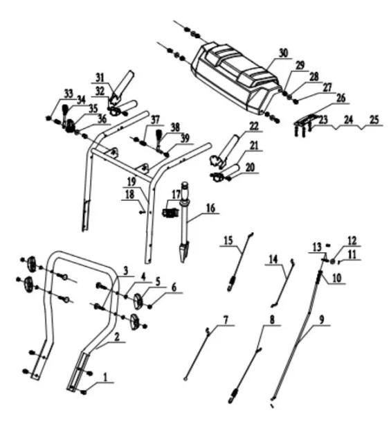
| Item |
Stock# |
Description |
Qty |
| 1 |
303020498 |
Hex Flange Screw M8X18 |
4 |
| 2 |
303080555 |
Lower Handle |
1 |
| 3 |
303020461 |
Washer Φ8 |
4 |
| 4 |
303043010 |
T-screw M8×55 |
4 |
| 5 |
203020336A |
Knob |
4 |
| 6 |
303030066 |
Nut M8 |
4 |
| 7 |
303200050 |
Lower Drive Cable |
1 |
| 8 |
303200012 |
Lower Auger Cable |
1 |
| 9 |
303071442 |
Speed Control Connection Rod |
1 |
| 10 |
303030076 |
Flange Normal Nut M8 |
2 |
| 11 |
303160846 |
Dowel Pin φ2 |
2 |
| 12 |
303042023 |
Flat Washer φ8×φ18×2 |
1 |
| 13 |
303123034 |
Connection Rod Pin Φ7 |
1 |
| 14 |
303200106 |
Upper Auger Cable |
1 |
| 15 |
303200130 |
Upper Drive Cable |
1 |
| 16 |
203050057 |
Clean Out Tool |
1 |
| 17 |
203050512 |
Rocker Seat |
1 |
| 18 |
303010164 |
Screw M6×20 |
1 |
| 19 |
303181160A |
Upper Handle Welding |
1 |
| 20 |
303020486 |
Hex Flange Bolt M6X50 |
2 |
| 21 |
203070105 |
Handle Cover |
2 |
| 22 |
303181183 |
Left Operation Trigger |
1 |
| 23 |
303010193 |
Screw 6×16 |
3 |
| 24 |
303042042 |
Flat Washer φ6×φ16×2 |
3 |
| 25 |
303160746 |
Cushion Cover |
3 |
| 26 |
303071343 |
DB7109 Gear Plate |
1 |
| 27 |
303020275 |
Hex Washer Bolt M8X40 |
4 |
| 28 |
303042013 |
Flat Washer φ8×φ22×2 |
4 |
| 29 |
303030077 |
Flange Lock Nut M8 |
4 |
| 30 |
203050373 |
Panel |
1 |
| 31 |
303071336 |
Right Operation Trigger |
1 |
| 32 |
303030130 |
Flang Nut |
2 |
| 33 |
303030077 |
Flang Lock Nut |
2 |
| 34 |
203070085 |
Control Handle |
1 |
| 35 |
203021099 |
Drive Cable Control Plate |
1 |
| 36 |
203020380 |
Tooth Gasket |
1 |
| 37 |
303130074 |
Spring |
2 |
| 38 |
203070102 |
Control Handle |
1 |
| 39 |
303020274 |
Hex Bolt M8X45 |
2 |
Chute Assembly
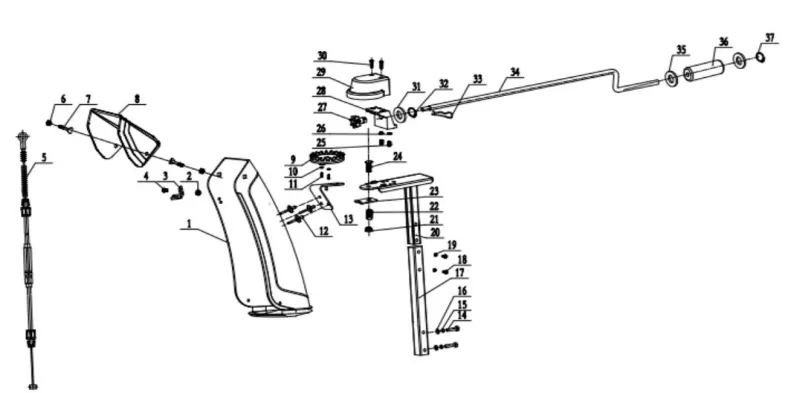
| Item |
Stock # |
Description |
Qty |
| 1 |
203050514 |
Chute |
1 |
| 2 |
303030087 |
Hex Flang Lock Nut M6 |
1 |
| 3 |
303071344 |
Cable Seat |
1 |
| 4 |
303020244 |
Hex Flang Bolt M6×14 |
1 |
| 5 |
303200117 |
Chute Cable |
1 |
| 6 |
303030077 |
Hex Flang Lock Nut M8 |
2 |
| 7 |
303020622 |
Bolt M8×20 |
2 |
| 8 |
203050515 |
Upper Chute |
1 |
| 9 |
203021301 |
Chute Steering gear |
1 |
| 10 |
303042019 |
Flat washer φ4×φ12×1 |
2 |
| 11 |
303010026 |
Screw 4x12 |
2 |
| 12 |
306110029 |
Rivet φ6×10 |
3 |
| 13 |
303071053 |
Steering Dead Plate |
1 |
| 14 |
303020275 |
Hex Bolt M8×40mm |
2 |
| 15 |
303041022 |
Spring Washer Φ8 |
2 |
| 16 |
303042023 |
Flat Washer φ8×φ18×2 |
2 |
| 17 |
303181010 |
Chute Support Tube Welding |
1 |
| 18 |
303020503 |
Hex Flang Bolt M6×35 |
2 |
| 19 |
303030087 |
Hex Flange Lock Nut M6 |
2 |
| 20 |
303181164 |
Small Support Tube Welded |
1 |
| 21 |
303030077 |
Locknut M8 |
1 |
| 22 |
303130325 |
Pressure Spring φ3 |
1 |
| 23 |
303071056 |
Locating Plate |
1 |
| 24 |
303020165 |
Square Bolt M8X55 |
1 |
| 25 |
303020246 |
Bolt M6x16 |
2 |
| 26 |
303030032 |
Locknut M6 |
2 |
| 27 |
303060131A |
Steering Pinion |
1 |
| 28 |
203010818 |
Steering Gear Seat |
1 |
| 29 |
203010817 |
Steering Gear Cover |
1 |
| 30 |
303010026 |
Screw 4x12 |
2 |
| 31 |
303043058 |
Flat Washer φ13.5×φ24×2 |
1 |
| 32 |
303050044 |
Shaft Ring φ13 |
1 |
| 33 |
303160845 |
Dowel Pin φ2.5 |
1 |
| 34 |
303160755A |
Z-long Rocker |
1 |
| 35 |
303042004 |
Flat Washer φ10×φ22×2 |
2 |
| 36 |
203020371 |
Rocker Lever |
1 |
| 37 |
303050029 |
Shaft Ring φ10 |
1 |
Frame Assembly
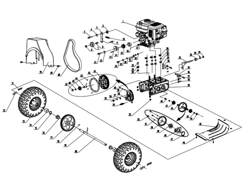
| Item |
Stock # |
Description |
Qty |
| 1 |
9999960501 |
Engine 212CC |
1 |
| 2 |
303160192 |
Small Tensioning Plate Spacer |
1 |
| 3 |
303070202 |
Small Tensioning Plate |
1 |
| 4 |
303042005 |
Flat Washer Φ8×Φ28×3 |
1 |
| 5 |
303020279 |
Outer Hex Flange Bolt M8x25 |
1 |
| 6 |
303030077 |
Flange Locknut M8 |
1 |
| 7 |
203100004 |
Tension Wheel Assembly |
1 |
| 8 |
303160195A |
Bushing |
1 |
| 9 |
303020154 |
Step Bolt M8x40 |
1 |
| 10 |
303130094 |
Friction Wheel Bracket Spring |
1 |
| 11 |
303020124 |
Flange Hex Bolt M8x35 |
1 |
| 12 |
303042005 |
Flat Washer Φ8×Φ28×3 |
1 |
| 13 |
Loncin BYO |
Flat key 4.7x70 |
1 |
| 14 |
303160152A |
V-belt Wheel |
1 |
| 15 |
303060041 |
Synchronous Pulley Wheel |
1 |
| 16 |
303060040 |
Adjustable Pad |
1 |
| 17 |
303160432 |
Screw |
1 |
| 18 |
303020279 |
Hex Bolt M8X20 |
1 |
| 19 |
303041022 |
Spring Washer Φ8 |
1 |
| 20 |
303042023 |
Flat Washer Φ8×Φ18×2 |
2 |
| 21 |
303080145 |
Belt Stop Lever Φ6 |
1 |
| 22 |
303043016 |
External Teeth Lock Washer Φ8 |
1 |
| 23 |
303160177 |
Guide Pulley Screw M6 |
1 |
| 24 |
203020364 |
Guide Pulley |
1 |
| 25 |
303030032 |
Locknut M6 |
1 |
| 26 |
303030066 |
Nut M8 |
4 |
| 27 |
303041022 |
Spring Washer Φ8 |
4 |
| 28 |
303042023 |
Flat Washer Φ8×Φ18×2 |
4 |
| 29 |
303030032 |
Locknut M6 |
2 |
| 30 |
303070418A |
Guide Wheel Plate |
1 |
| 31 |
303181227 |
Gear Shift Fork Welded |
1 |
| 32 |
303160308 |
Friction Wheel Support Shaft Sleeve Tube |
1 |
| 33 |
303160830 |
Shift Pick |
1 |
| 34 |
303030077 |
Flange Lock Nut M8 |
1 |
| 35 |
303071243 |
Guide wheel plate |
1 |
| 36 |
203020364 |
Guide Pulley |
2 |
| 37 |
303160177 |
Guide Pulley Screw M6X35 |
2 |
| 38 |
303020444 |
Flange Hex Bolt M6X12 |
4 |
| 39 |
303181006 |
Frame Welded |
1 |
| 40 |
303020239 |
Hex Flange Bolt M10X20 |
1 |
| 41 |
303100051 |
Grooved Deep Groove Ball Bearing |
2 |
| 42 |
303160799 |
Six Square Axis |
1 |
| 43 |
303042004 |
Flat Washer Φ10*Φ22*2 |
2 |
| 44 |
303343043 |
Locknut M10 |
1 |
| 45 |
303525287 |
Big Bottom Plate |
1 |
| 46 |
303586035 |
Triangular Head Bolt |
4 |
| 47 |
303050027 |
Shaft Ring Φ30 |
1 |
| 48 |
303210036 |
Fork Riveting |
1 |
| 49 |
303160803 |
Six Square Sleeve |
1 |
| 50 |
202170009 |
Friction Wheel Assembly |
1 |
| 51 |
303041009 |
Spring Washer Φ6 |
3 |
| 52 |
303020244 |
Hex Flange Bolt M6×14 |
3 |
| 53 |
303030077 |
Hex Flange Nut |
4 |
| 54 |
303130094 |
Friction Wheel Bracket Spring |
1 |
| 55 |
304315011 |
Serrated Nut |
1 |
| 56 |
304375759 |
Elastic Washer |
1 |
| 57 |
303042004 |
Flat Washer |
1 |
| 58 |
303181163 |
Friction Wheel Support Welding |
1 |
| 59 |
304132767 |
Flat Washer |
1 |
| 60 |
303020244 |
Outer Hex Flange Bolt M6×14 |
1 |
| 61 |
303160801 |
Large Synchronous Belt Pulley |
1 |
| 62 |
304618751 |
Rim |
1 |
| 63 |
304679499 |
Screw M6×10 |
6 |
| 64 |
303160802 |
Large Synchronous Belt Shaft |
1 |
| 65 |
304800995 |
Deep Groove Ball Bearing 6203Z |
1 |
| 66 |
303042169 |
Flat Washer Φ17×Φ24×3 |
1 |
| 67 |
303050519 |
Ring Φ40 |
1 |
| 68 |
302040078 |
Synchronous belt |
1 |
| 69 |
304922491 |
Flange bolt M6X12 |
2 |
| 70 |
203050335 |
Belt cover |
1 |
| 71 |
303160845 |
Dowel Pin 1 Φ2.5 |
2 |
| 72 |
303160815 |
Dowel Pin 2 Φ6 |
2 |
| 73 |
302090217 |
13" Wheel Assembly |
2 |
| 74 |
305165483 |
Spacer Bush |
2 |
| 75 |
305226231 |
Shaft Ring Φ19 |
1 |
| 76 |
305286979 |
Bushing |
2 |
| 77 |
305347727 |
Big Gear |
1 |
| 78 |
305408475 |
Woodruff Key 5×7.5×19 |
1 |
| 79 |
305469223 |
Elastic cylindrical pin 5×30 |
1 |
| 80 |
305529971 |
Axle |
1 |
Auger Housing Assembly
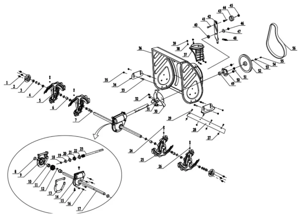
| Item |
Stock# |
Description |
Qty |
| 1 |
303020245 |
Hex Flange Bolt M8X14 |
6 |
| 2 |
303070234 |
Bearing Block |
2 |
| 3 |
203060013 |
Plastic Bearing |
2 |
| 4 |
203060012 |
Auger Sleeve |
8 |
| 5 |
303180409 |
Right Auger Welding |
2 |
| 6 |
203050108 |
Spacer Bush 1 |
4 |
| 7 |
203050109 |
Spacer Bush 2 |
8 |
| 8 |
302130005 |
Skeleton seal Φ19×Φ32×7 |
2 |
| 9 |
303090032 |
Worm gear Box Left |
1 |
| 10 |
303060055 |
Worm Gear Shaft Sleeve |
2 |
| 11 |
303090033 |
Worm Gear |
1 |
| 12 |
303110022 |
Woodruff Key |
1 |
| 13 |
303070260 |
Worm Gear Shaft Sleeve |
1 |
| 14 |
303090031 |
Worm gear Box Right |
1 |
| 15 |
303020142 |
Bolt M8x10 |
2 |
| 16 |
303020489 |
M6x18 |
6 |
| 17 |
303160370 |
Auger Axle |
1 |
| 18 |
303100030 |
Deep groove ball bearing 6001Z |
1 |
| 19 |
303100035 |
Deep groove ball bearing 6904Z |
1 |
| 20 |
303070179 |
Worm Box Washer |
1 |
| 21 |
303100039 |
Bearing 51104 |
1 |
| 22 |
302130002 |
Skeleton seal Φ20×Φ35×7 |
1 |
| 23 |
303160314 |
Worm |
1 |
| 24 |
303160355 |
Shear Pin |
4 |
| 25 |
303180410 |
Auger Welding Left |
2 |
| 26 |
303030032 |
Lock Nut M6 |
4 |
| 27 |
303030076 |
Flang Normal Nut M8 |
4 |
| 28 |
303071330 |
24" Shave |
1 |
| 29 |
303020332 |
Bolt M8×14 |
4 |
| 30 |
303181158 |
Impeller |
1 |
| 31 |
303030032 |
Lock Nut M6 |
2 |
| 32 |
303020442 |
Hex Washer Bolt φ6×35 |
2 |
| 33 |
303020166 |
Bolt M8×18 |
4 |
| 34 |
303070197 |
Skid Shoes |
2 |
| 35 |
303030077 |
Flang Lock Nut M8 |
4 |
| 36 |
303181159 |
Auger Housing Welding |
1 |
| 37 |
203050511 |
Lower chute seat |
1 |
| 38 |
303020341 |
Bolt M6×16 |
4 |
| 39 |
303030087 |
Flange Lock Nut M6 |
4 |
| 40 |
303160192 |
Small Tensioning Plate Spacer |
1 |
| 41 |
303020154 |
Bolt M8×40 |
1 |
| 42 |
303071345 |
Big Tension Plate |
1 |
| 43 |
303160195A |
Tensioning Wheel Casing |
1 |
| 44 |
203100003 |
Tensioning Wheel Assembly |
1 |
| 45 |
303030077 |
Flange Lock Nut M8 |
1 |
| 46 |
303030059 |
Lock Nut M10 |
1 |
| 47 |
303042078 |
Flat Washer φ10×φ30×2 |
3 |
| 48 |
303160175 |
Large Tensioning Plate Tension Spring |
1 |
| 49 |
303100040 |
Bearing |
1 |
| 50 |
303070233 |
Bearing Plate |
1 |
| 51 |
303030077 |
Flang M8 |
3 |
| 52 |
303160794A |
7109 Big Pulley |
1 |
| 53 |
303110014 |
Flat Key C6X18 |
1 |
| 54 |
303042005 |
Flat Washer φ8×φ28×3 |
1 |
| 55 |
303020279 |
Hex Washer M8×20 |
1 |
| 56 |
302040079 |
V-Belt 720mm,4LXA |
1 |
Engine Explode View and Bom List
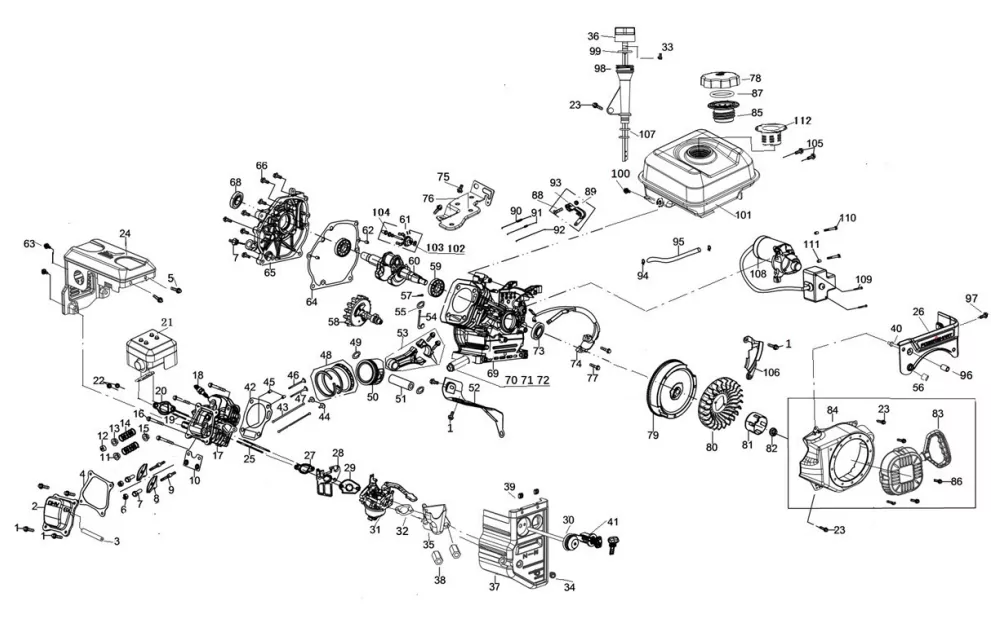
| Item |
Stock# |
Description |
Qty |
| 1 |
303020444 |
Hexagon Head Flange Bolt M6X12 |
7 |
| 2 |
9020960102 |
Breathing cover |
1 |
| 3 |
9051960302 |
muffler pipe |
1 |
| 4 |
9245960103 |
Cylinder Head Cover Gasket |
1 |
| 5 |
303020382 |
Screw M6X12 |
2 |
| 6 |
9143960101 |
Air lock nut |
2 |
| 7 |
9143960102 |
Valve clearance adjusting nut |
2 |
| 8 |
9230960101 |
Valve rocker |
2 |
| 9 |
9142960101 |
Rocker seat locating bolt |
2 |
| 10 |
9220960101 |
Push rod guide plate |
1 |
| 11 |
9170960102 |
Intake valve spring seat |
1 |
| 12 |
9402960101 |
Exhaust valve adjusting cap |
1 |
| 13 |
9170960103 |
Exhaust valve spring seat |
1 |
| 14 |
9531960101 |
Valve spring |
2 |
| 15 |
9245960101 |
Oil shield assembly |
1 |
| 16 |
303020620 |
Bolt M8X60 |
4 |
| 17 |
9020960101 |
Cylinder head assembly |
1 |
| 18 |
9566960301 |
Spark Plug |
1 |
| 19 |
303010324 |
Muffler stud |
2 |
| 20 |
9245960105 |
Muffler gasket |
1 |
| 21 |
9569960301 |
Muffler assembly |
1 |
| 22 |
303030111 |
Nut M8 |
2 |
| 23 |
303020382 |
Bolt M6X12 |
4 |
| 24 |
9569960302 |
Muffler housing |
1 |
| 25 |
303010323 |
Carburetor stud |
2 |
| 26 |
9225960302 |
Fuel tank panel |
1 |
| 27 |
9245960107 |
Seal gasket |
1 |
| 28 |
9535960101 |
Thermal baffle |
1 |
| 29 |
9245960108 |
Seal gasket |
1 |
| 30 |
9532960301 |
Primer pump assembly |
1 |
| 31 |
9568960501 |
carburetor assy |
1 |
| 32 |
9245960102 |
Empty filter washer |
1 |
| 33 |
303010095 |
Self tapping screw ST4X14 |
1 |
| 34 |
303020382 |
Bolt M6X12 |
2 |
| 35 |
9170960101 |
Empty filter holder |
1 |
| 36 |
9198960102 |
High oil ruler cover |
1 |
| 37 |
9225960301 |
Switch panel |
1 |
| 38 |
303020514 |
Hexagon nut |
2 |
| 39 |
303030136 |
Square nut |
2 |
| 40 |
303030135 |
Stud |
2 |
| 41 |
9440960102 |
Key switch assembly |
1 |
| 42 |
9245960204 |
Cylinder head gasket |
1 |
| 43 |
9013960101 |
Push Rod |
2 |
| 44 |
9536960101 |
Valve lifter |
2 |
| 45 |
9140960102 |
Location pin |
2 |
| 46 |
9113960102 |
Exhaust valve |
1 |
| 47 |
9113960101 |
Intake valve |
1 |
| 48 |
9564960501 |
Piston ring assembly |
1 |
| 49 |
9146960501 |
Gudgeon pin circlip |
2 |
| 50 |
9129960501 |
Piston |
1 |
| 51 |
9140960501 |
Piston pin |
1 |
| 52 |
9221960102 |
Fairwater |
1 |
| 53 |
9015960501 |
Connecting rod |
1 |
| 54 |
9005960101 |
Throttle governor handle |
1 |
| 55 |
303043040 |
Wash er |
1 |
| 56 |
9140960106 |
Bush |
6 |
| 57 |
9534960101 |
Split cotter |
1 |
| 58 |
9158960301 |
Camshaft assembly |
1 |
| 59 |
9158960501 |
Bearing |
2 |
| 60 |
9122960501 |
Crankshaft assembly |
1 |
| 61 |
9438960101 |
Speed regulating driven gear combination |
1 |
| 62 |
9140960103 |
Location pin |
1 |
| 63 |
303020382 |
Bolt M6X12 |
2 |
| 64 |
9245960106 |
Case gasket |
1 |
| 65 |
9563960102 |
Left crankcase cover |
1 |
| 66 |
303020509 |
Bolt M8X32 |
6 |
| 67 |
9198960101 |
Oil lever gauge |
1 |
| 68 |
9246960101 |
Oil seal |
2 |
| 69 |
9563960101 |
Crankshaft box body |
1 |
| 70 |
303020518 |
Drain bolt |
1 |
| 71 |
303043042 |
Aluminum washer |
1 |
| 72 |
303020508 |
Purge cock |
1 |
| 73 |
9246960101 |
Oil Seal |
1 |
| 74 |
9565960301 |
Igniter assembly |
1 |
| 75 |
303020444 |
Hexagon head flange bolt |
2 |
| 76 |
9228960301 |
Governor seat fixing plate |
1 |
| 77 |
303020490 |
Bolt M6X25 |
2 |
| 78 |
9529960302 |
Fuel tank cap |
1 |
| 79 |
9152960501 |
Flywheel components |
1 |
| 80 |
9414960101 |
Fan |
1 |
| 81 |
9194960101 |
Passive plate |
1 |
| 82 |
303020511 |
Nut M14X1.5 |
1 |
| 83 |
9528960101 |
Starter assembly |
1 |
| 84 |
9226960301 |
Wind scooper |
1 |
| 85 |
9529960103 |
Oil tank screw cap |
1 |
| 86 |
303020515 |
Bolt M6X8 |
4 |
| 87 |
9247960103 |
O ring |
1 |
| 88 |
303020513 |
T-Bolt |
1 |
| 89 |
303030112 |
Hexagon flange nut with teeth |
1 |
| 90 |
9332960101 |
Speed regulating tension spring |
1 |
| 91 |
9332960102 |
Throttle tension spring |
1 |
| 92 |
9013960102 |
Choke putter |
1 |
| 93 |
9230960101 |
Plunger arm |
1 |
| 94 |
9533960201 |
Tubing clamp |
2 |
| 95 |
9051960301 |
Oil Tube |
1 |
| 96 |
9140960306 |
Bush |
1 |
| 97 |
303020382 |
Bolt M6X12 |
1 |
| 98 |
9198960103 |
Oil ruler |
1 |
| 99 |
9247960102 |
O-ring |
1 |
| 100 |
303020382 |
Bolt M6X12 |
1 |
| 101 |
9529960301 |
Fuel tank assembly |
1 |
| 102 |
9121960101 |
Governing gear shaft |
1 |
| 103 |
303043040 |
Washer |
2 |
| 104 |
9092960101 |
Slide bushing |
1 |
| 105 |
303020382 |
Bolt M6X12 |
2 |
| 106 |
9221960101 |
Flywheel side housing |
1 |
| 107 |
9247960101 |
O-ring |
1 |
| 108 |
9421960101 |
Starting motor assembly |
1 |
| 109 |
303020517 |
Bolt M4X55 |
2 |
| 110 |
303020512 |
Bolt M6X30 |
2 |
| 111 |
9140960104 |
Locating pin |
2 |
| 112 |
9115960101 |
Fuel filter |
1 |
TWO (2) YEARS LIMITED WARRANTY
PowerSmart is committed to building tools that are dependable for years. Our warranties are consistent with our commitment and dedication to quality.
TWO (2) YEARS LIMITED WARRANTY OF POWER SMART PRODUCTS FOR HOME USE.
(“Seller") warrants to the original purchaser only, that all PowerSmart consumer power tools will be free from defects in material or workmanship for a period of two (2) years from date of purchase. Ninety (90) days for all PowerSmart Products, if the tool is used for professional or commercial use.
SELLER’S SOLE OBLIGATION AND YOUR EXCLUSIVE REMEDY under this Two (2) Years Limited Warranty and, to the extent permitted by law, any warranty or condition implied by law, shall be the repair or replacement of parts, without charge, which are defective in material or workmanship and which have not been misused, carelessly handled, or misrepaired by persons other than Seller or Authorized Service Center. To make a claim under this Limited Warranty, you must return the entire power tool product; transportation prepaid, to PowerSmart Include a legible copy of the original receipt, which lists the date of purchase (month and year) and the name of the company purchased from.
THIS LIMITED WARRANTY DOES NOT APPLY TO ANY ACCESSORY ITEMS INCLUDED WITH THE TOOL SUCH AS CIRCULAR SAW BLADES OTHER RELATED ITEMS OR TO ANY REPLACEMENT PARTS LISTED UNDER MAINTENANCE.
ANY IMPLIED WARRANTIES SHALL BE LIMITED IN DURATION TO TWO (2) YEARS FROM DATE OF PURCHASE. SOME STATES IN THE U.S. AND SOME CANADIAN PROVINCES DO NOT ALLOW LIMITATIONS ON HOW LONG AN IMPLIED WARRANTY LASTS, SO THE ABOVE LIMITATION MAY NOT APPLY TO YOU.
IN NO EVENT SHALL SELLER BE LIABLE FOR ANY INCIDENTAL OR CONSEQUENTIAL DAMAGES (INCLUDING BUT NOT LIMITED TO LIABILITY FOR LOSS OF PROFITS) ARISING FROM THE SALE OR USE OF THIS PRODUCT. SOME STATES IN THE U.S. AND SOME CANADIAN PROVINCES DO NOT ALLOW THE EXCLUSION OR LIMITATION OF INCIDENTAL OR CONSEQUENTIAL DAMAGES, SO THE ABOVE LIMITATION OR EXCLUSION MAY NOT APPLY TO YOU.
THIS LIMITED WARRANTY GIVES YOU SPECIFIC LEGAL RIGHTS, AND YOU MAY ALSO HAVE OTHER RIGHTS WHICH VARY FROM STATE TO STATE IN THE U.S., PROVINCE TO PROVINCE IN CANADA AND FROM COUNTRY TO COUNTRY.
For questions / comments, technical assistance or repair parts – Please call toll free at: 1-800-791-9458 (M-F 9am – 5pm EST)
Email: [email protected]
SAVE YOUR RECEIPTS. THIS WARRANTY IS VOID WITHOUT THEM.