Loading ...
Loading ...
Installation 3
Pi ping – Sewage Applications (2” or
LessSolids)
In any case, piping must not be smaller than pump discharge
.
When installed in a sewage system, pipe must be capable
of handling semi-solids of at least 2” (5.1 cm) diameter.
The rate of flow in the discharge pipe must keep any
solids present in suspension in the fluid. To meet
minimum flow requirements (2 feet (.6 m) per second in
discharge line), size pipe as follows:
NOTICE Use PTFE pipe thread sealant tape on pipe
connections. Do not use ordinary pipe joint compound
on plastic pipe or pump. Pipe joint compound can attack
plastics and damage pump.
3. To reduce motor noise and vibrations, a short length
of rubber hose (1-5/8”(41mm) I.D., e.g. radiator
hose) can be connected into discharge line near
pump using suitable clamps.
4. If the pump discharge line is exposed to outside
subfreezing atmosphere, then the portion of line
exposed must be installed so any water remaining
in pipe will drain to outfall by gravity. Failure to do
this can cause water trapped in discharge to freeze
which could result in damage to pump.
5. Install a 2” check valve in the horizontal portion of
the discharge pipe. Make certain, the flow indicating
arrow, points away from the pump. This check valve
will keep the water from either running back into the
basin or into the area being pumped out when the
pump is not running. Check valve should be a free
flow valve that will easily pass solids.
NOTICE For best performance of check valve when
handling solids, do not install it with discharge angled
more than 45° above the horizontal. Do not install check
valve in a vertical position as solids may settle in valve
and prevent opening on startup.
6. Drill a 3/16” (4.7mm) hole in discharge pipe
about 1”-2” (2.5 - 5.1cm) above pump discharge
connection (but below check valve) to prevent
airlocking the pump.
7. Insert the float switch piggy-back plug into a
properly grounded outlet and the pump plug into the
piggy-back plug.
8.
Check the installation by observing the pump
operation through one complete cycle. Make sure that
no parts of the assembly interfere with the float switch.
Risk of flooding. Can cause personal injury
and/or property damage. Failure to make this operational
check may lead to improper operation, premature failure,
and flooding.
Electrical
Risk of electric shock. Can shock, burn or
kill. When installing, operating, or servicing this pump,
follow safety instructions listed below.
1. DO NOT splice the electrical power cord.
2. DO NOT allow electrical cord plug to be submerged.
3. DO NOT use extension cords. They are a fire hazard
and can reduce voltage sufficiently to prevent
pumping and/or damage motor.
4. DO NOT handle or service pump while it is connected
to power supply.
5. DO NOT remove grounding prong from plug or
modify plug.To protect against electrical shock, the
power cord is a three-wire conductor and includes
a 3-prong grounded plug. Plug pump into a 3-wire,
grounded, grounding-type receptacle. Connect pump
according to electrical codes that apply.
For parts or assistance, call Simer Customer Service at 800-468-7867
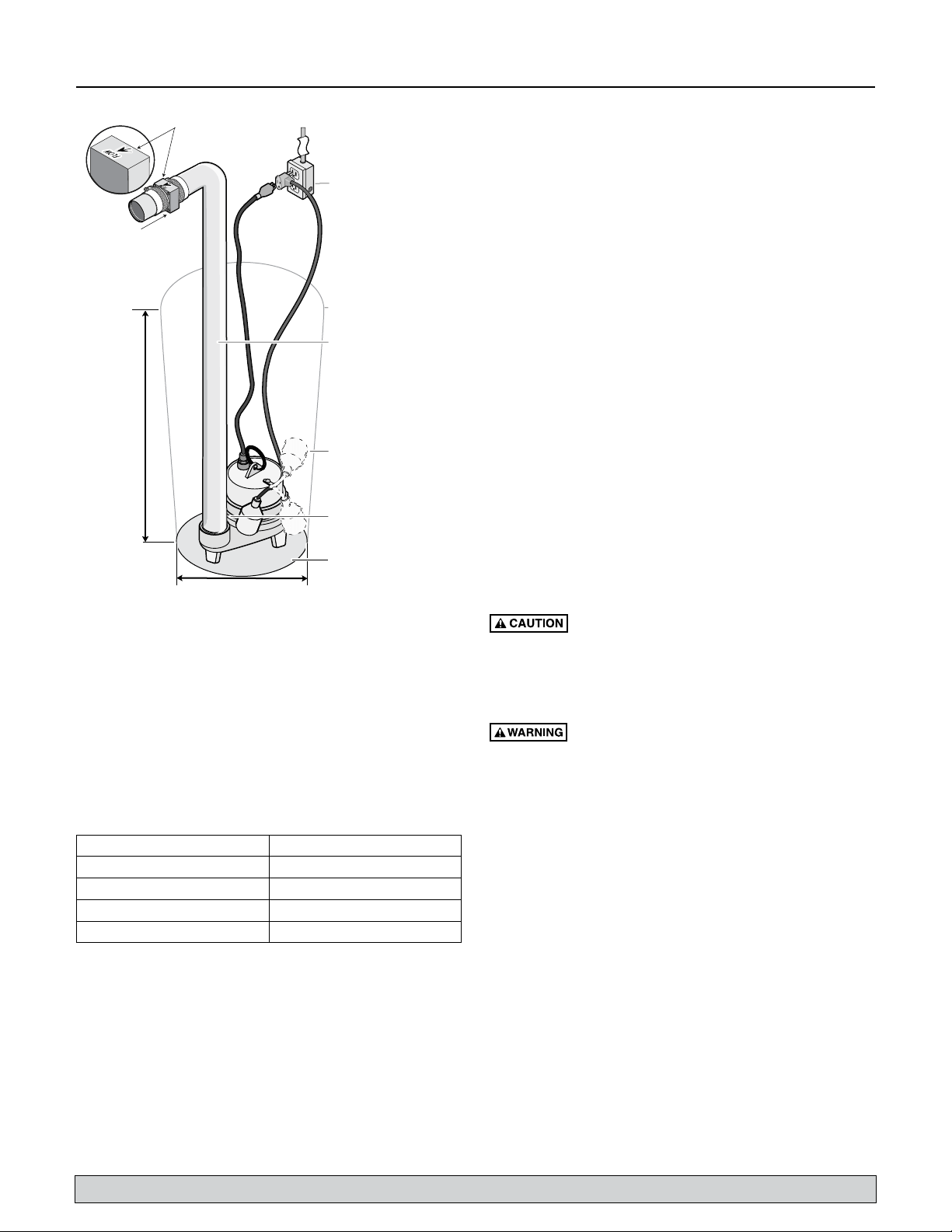
Figure 1
Sump Pit Installation
18"
2" Checkvalve
Do Not Mount
Vertically
30"
Sump Pit
2" Discharge
Pipe
115V Properly
Grounded
Outlet
Install pump on
a hard, level surface.
Drill a 3/16"
vent hole here.
Be sure the
float switch can
swing through
it's entire arc.
Flow
Directional
Arrow
3620 1199 S185 Install
A Pipe Size of: Will Handle a Flow Rate of:
1-1/2” (3.8 cm) 12 GPM (45 LPM)
2” (5.1 cm) 21 GPM (79 LPM)
2-1/2” (6.3 cm) 30 GPM (113 LPM)
3” (7.6 cm) 48 GPM (181 LPM)
Loading ...
Loading ...
Loading ...