Loading ...
Loading ...
Loading ...
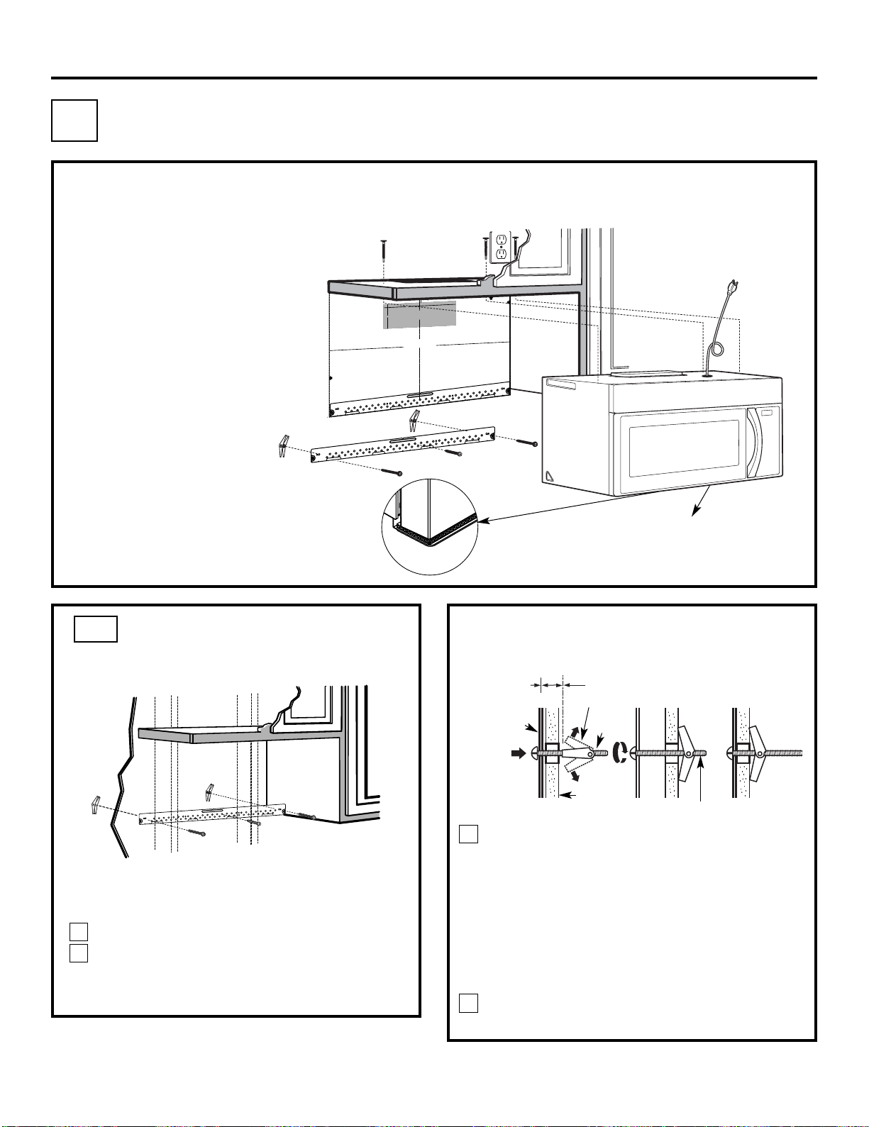
Place the mounting plate against the wall and
insert the toggle wings into the holes in the wall
to mount the plate.
NOTE: Before tightening toggle bolts and wood
screw, make sure the bottom of the mounting plate
touch the bottom of the cabinet when pushed
flush against the wall and that the plate is properly
centered under the cabinet.
CAUTION: Be careful to avoid pinching fingers
between the back of the mounting plate and the wall.
Tighten all bolts. Pull the plate away from the wall
to help tighten the bolts.
3
4
ATTACH THE MOUNTING
PLATE TO THE WALL
A1.
Attach the plate to the wall using toggle bolts.
At least one wood screw must be used to attach
the plate to a wall stud.
Remove the toggle wings from the bolts.
Insert the bolts into the mounting plate
through the holes designated to go into drywall
and reattach the toggle wings to
3
⁄4″ (19 mm) onto
each bolt.
1
INSTALLATION OVERVIEW
A1. Attach Mounting Plate to Wall
A2. Prepare Top Cabinet
Mount Microwave Oven
A5.
Adjust Exhaust Adaptor
A6.
Wall
Mounting
Plate
Spacing for Toggles
More Than Wall
Thickness
Bolt End
Toggle
Bolt
Toggle Wings
To use toggle bolts:
Installation Instructions
2
OUTSIDE TOP EXHAUST (Vertical Duct)
A
IMPORTANT NOTES:
• Make sure the screws for the
blower motor and blower plate
are securely tightened when
they are reinstalled. This will
help to prevent excessive
vibration.
• Make sure the motor wiring has
been properly routed and secured,
and that the wires are not pinched.
A7. Connect Ductwork
A3.
A4.
Check Damper Operation
Adapting Microwave Blower for
Outside Top Exhaust
EN-12
3/8"
TO
EDG
E
%#
76
+
10
Ä
+(':*#756
#&#
2614+5215+6
+10'&176
5+&'
4'%
1/
/'0&'&
&
+/'0
5+10
)4'#
5'Ä.
#
&'0#
+49+.
.
&+5%
*#
4)'
+06
1*175'56
4
7%6
74
'
/
+0+/7/9+&6*4'37+4'&
4'#49#..6'/2.#6'
NO
TE
:
IT IS
VERY
I
MPO
R
TANT TO
READ AND FO
LLO
W
T
HE
D
IRECTIO
NS
IN THE INSTALLA
T
ION INSTRU
CTI
ONS
BE
FO
RE PR
O
CEEDING
WITH
T
H
IS
REAR W
A
LL TEM
PLA
TE
.
Th
i
s
R
e
a
rWa
ll Te
mpl
a
te
s
e
r
v
e
s to p
o
sitio
n
th
e
b
o
tto
m
mou
ntin
g
p
la
te
a
nd
to l
oc
a
te th
e ho
r
i
z
on
ta
l e
xh
au
s
t
ou
t
le
t.
1
. Us
e a l
e
v
el
to
c
h
ec
k
th
a
t the
t
e
m
pla
te
i
s
p
o
s
itioned
a
c
cu
r
a
tely
.
2. L
o
c
ate
a
ndm
a
r
k
a
t lea
st o
nes
tu
d
on th
e
le
ft o
r
r
ight
s
id
e
o
f th
e c
e
n
te
rl
i
n
e
.
016
'
It
is imp
o
rt
a
n
t to u
s
e
a
t le
as
t
one
wo
od
sc
re
w
mo
unted fi
r
mly
i
n
a
s
tud
to supp
or
t the w
e
ight
of
th
e mic
r
o
w
a
ve.
M
a
r
k
t
w
o
a
d
di
ti
on
a
l, ev
e
n
ly
s
pa
c
ed
lo
ca
tio
n
s f
o
r
the
s
u
ppl
ied to
g
gle bol
t
s.
3. Dr
i
ll
h
ol
e
s
in
th
e
m
ar
k
e
d lo
catio
n
s
.
Wher
e t
h
er
e is
a
s
tu
d
,
d
r
il
l
a 3/1
6"
h
ol
e
fo
r
woo
d sc
r
e
w
s
.
F
o
r
h
o
les
th
at
do
n
o
t lin
e up
with
a
s
tu
d, d
r
il
l 5
/8
"
h
o
le
s
fo
r
to
gg
l
e bo
lts
.
016
'
DO
NOT
I
NS
T
AL
L
T
HE
MO
U
NTI
N
G
P
L
ATE
AT
T
HIS
T
IME.
4. Re
m
o
v
e
th
e te
mpla
te
fr
o
m
the rea
r
wal
l.
5.
Rev
ie
w
th
e In
s
ta
ll
a
ti
onInst
r
uc
ti
o
n bo
ok
for
y
ou
r
in
s
ta
l
l
a
ti
o
n si
tua
t
i
on
.
Locate and m
ar
k
holes
to ali
gn with holes
in t
he
mounting
p
l
ate.
IMP
O
RTANT
:
LO
C
A
T
E
AT LEAST O
N
E
STUD
O
N EI
T
HER
SI
DE
O
F
TH
E
CENT
E
R
LI
NE
.
MARK
T
HE LO
CATIO
NF
O
R 2 ADDIT
IO
N
A
L, EVENLY
SP
ACE
D T
O
GGLE
BO
LTS IN
THE MO
UN
TING
PLATE
AREA
.
Locate and mar
k
holes
to al
i
gn with holes
in t
he
mounting
plate.
IMPORTANT
:
LO
C
A
T
E
AT LEAST O
N
ESTUD ON EI
THER SI
D
E
O
F
TH
E
CENT
E
R
LI
N
E
.
MARK
T
HE LO
CATIO
N
FO
R 2 ADDITION
A
L, EV
ENL
Y
SP
ACED
TOG
GLE BO
LTS IN
THE MO
UNTING
PLATE
AREA
.
Trim the r
e
ar
wal
l tem
plat
e along
the do
tt
ed
line.
Trim the rear
wal
l t
empla
t
e along
t
he dotted lin
e.
%
(%76176(14*14+<106#.
1765+&'':*#756
%7
6
*1.
'6
*4
17)*
4'#4
9#.
.
(
1
4
':*#
756#
6
1
4
12"
4"
Da
r
l
e
v
u
e
lt
a
a
la
ho
j
a
pa
r
a
c
o
ns
ul
t
a
r
la
v
e
r
s
i
ón
e
n
E
s
pa
ño
l.
IMPORTANT :Do not remove the cardboard
etween the heat shield and door.
spacers b
Loading ...
Loading ...
Loading ...