Loading ...
Loading ...
Loading ...
Installation
HP Cylinder
Installatio
n and User Instructions R03184
-4 09/15
Page
21
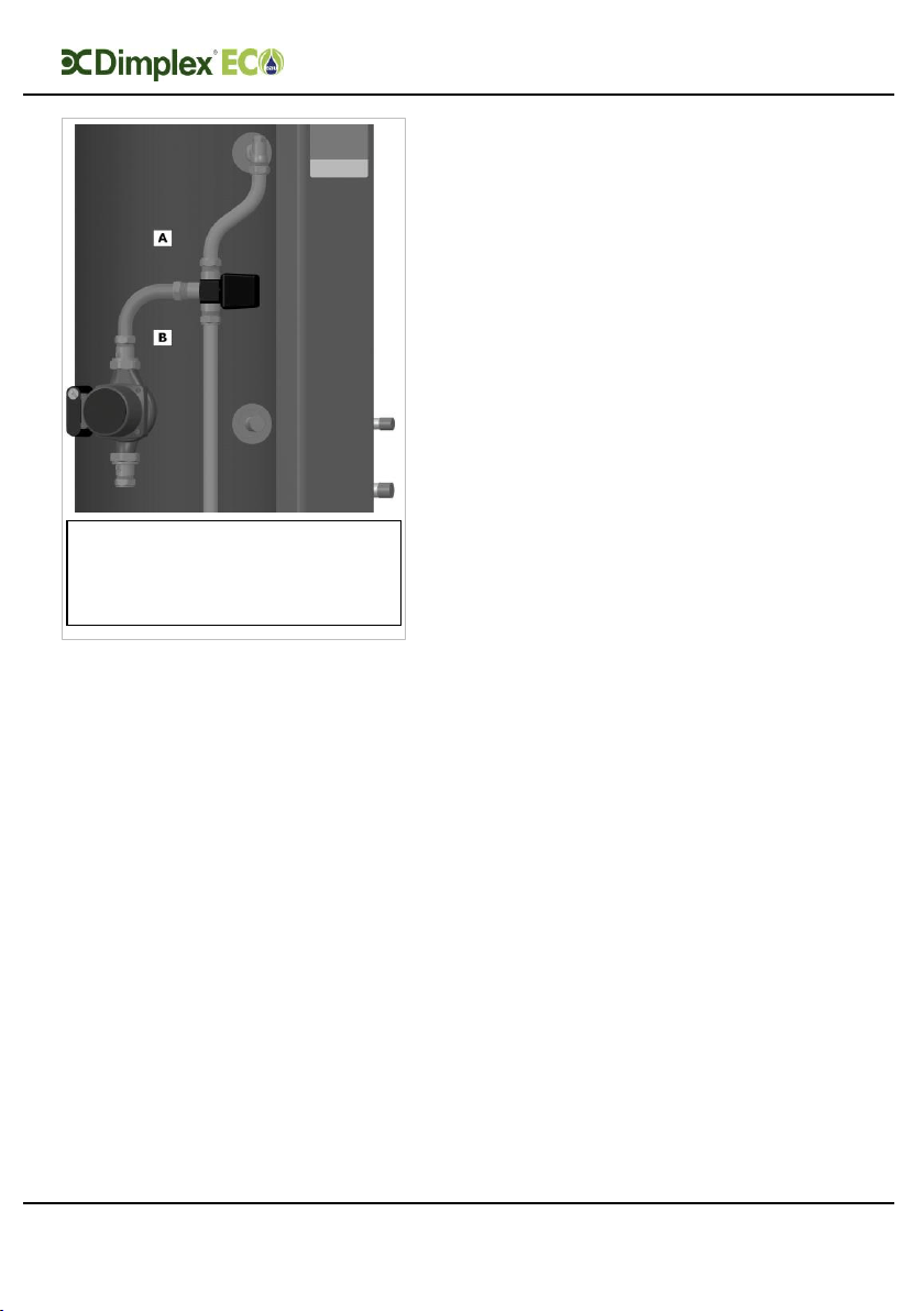
Figure 6: Diagram Showing Positions of
Valve
4.7 HP Flow to Buffer
The cylinder buffer flow connection
must be connected to a three port
valve which diverts flow between the
buffer cylinder and DHW cylinder
heating coil.
4.8 Buffer Flow to HP
The cylinder buffer flow to HP
connection must be connected in series
with the heat emitter system/under
floor heating.
4.9 Cylinder Thermostat &
Heat Pump Sensor
Connections
To conform to building regulations, it is
imperative that the heating water
circulating pump(s) be installed
through the cylinder twin
thermostat(s) – applicable to non A
Class cylinder only.
Also, a two port valve(s) has to be
wired after the thermostat, ensuring
compliance with building regulations.
This is applicable to each heat source
entering the water cylinder.
Should a Dimplex Heat Pump be
installed with the cylinder, it is
sufficient to use the temperature
sensor to control the heat input to the
cylinder and ignore Section 5.9.1.
4.9.1 Thermostat
Connections
For A Class cylinder and heat pump
cylinders this connection is prewired.
Where a non A Class cylinder is used
the cylinder thermostat must be wired.
After the sensor and cylinder
thermostat are connected, the
thermostat temperature setting can be
adjusted such that the sensor takes
primary control of the system, i.e. set
the cylinder thermostat to maximum
setting but allow the sensor to control
desired temperature levels.
To access the thermostat connections,
the cover panel should be removed
from the cylinder. To do this, simply
remove the fixing screws from the side
of the cylinder cover panel top and
bottom where highlighted in
.
Legend:-
A = HP Flow
B = HP Flow to Buffer
Loading ...
Loading ...
Loading ...