Loading ...
Loading ...
Loading ...
22 English
Installation Instructions
Installing the Anti-Tip Bracket and Foot, cont.
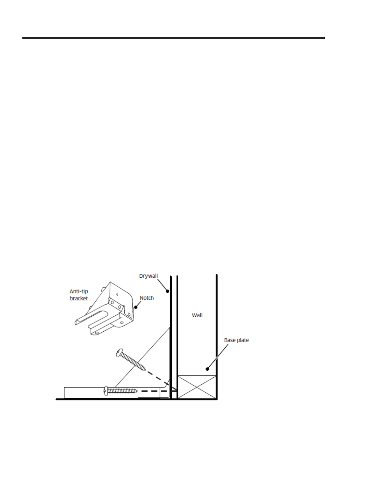
Wall-Mounting the Anti-Tip Bracket
For this option to be suitable, the range front panel must be 26 1/2" (67.3 cm) or less from the wall,
and the bracket screws must be able to engage the base plate inside the wall. Notches on the sides
will not impede secure threading.
To determine if the base height is suitable:
• -
sition based on the product dimensions on Pg. 14 and the actual cabinet/cutout dimensions used
for the installation.
• Determine and mark the required position of the anti-tip bracket, based on the diagram on Pg. 21.
Push the bracket up against the wall in the mounting location.
• With a pencil, make a dot next to the notches on both sides of the bracket. Determine if the base
plate is as high as the notches by drilling test holes into the wall at both dots with a 1/16” drill bit.
Drill just deep enough to see if the bit contacts the base plate. If there is contact, the location will
support wall installation of the bracket. If there is no contact, wall mounting is unsuitable, and
the notches.
To install the bracket, place it against the wall in the mounting location. Using a drill with 1/8" diam-
eter drill bit, drill four (4) 1 5/8” deep pilot holes perpendicular to the screw seating surfaces shown
below. Attach the bracket to the wall as shown with the four (4) included #12 x 1
¾ screws.
Loading ...
Loading ...
Loading ...