
Loading ...
Loading ...
Loading ...
W415-2339 / C / 02.08.21
EN
36
11.0 adjustment
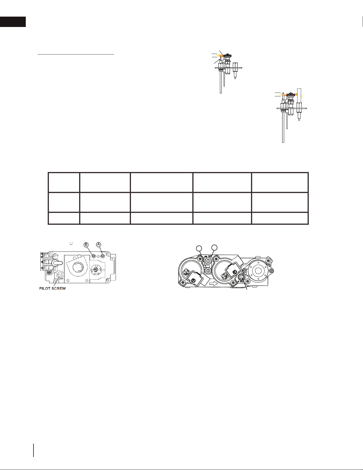
11.1 pilot burner adjustment
Adjust the pilot screw to provide properly sized fl ame. Turn in a clockwise direction to reduce the gas fl ow.
Check Pressure Readings:
Inlet pressure can be checked by turning screw (A) counter-
clockwise 2 or 3 turns and then placing pressure gauge tubing
over the test point. Gauge should read as described on the chart
below. Check pressure with main burner operating on “HI”.
Outlet pressure can be checked the same as above using screw
(B). Gauge should read as described on the chart below. Check
pressure with main burner operating on “HI”.
After taking pressure readings, be sure to turn screws
clockwise fi rmly to reseal. Do not overtorque.
Leak test with a soap and water solution.
Prior to pilot adjustment, ensure that the pilot assembly has not been painted. If overspray or painting of
the pilot assembly has occurred remove the paint from the pilot assembly, or replace. Fine emery cloth or a
synthetic scrub pad (such as Scotch-Brite
™)
can be used to remove the paint from the pilot hood, electrode
and fl ame sensor.
INSERT PILOT ASSEMBLY
*Maximum inlet pressure not to exceed 13”
Pressure Natural Gas
(inches)
Natural Gas
(millibars)
Propane
(inches)
Propane
(millibars)
Inlet
*7”
(minimum 4.5”)
17.4mb
(minimum 11.2mb)
13”
(minimum 11”)
32.4mb
(minimum 27.4mb)
Outlet
3.5” 8.7mb 10” 24.9mb
A
B
PILOT SCREW
ELECTRONIC
MILLIVOLT
FLAME MUST ENVELOP
UPPER 3/8” (9.5mm) TO 1/2”
(12.7mm) OF FLAME SENSOR
PILOT
BURNER
ELECTRODE
FLAME
SENSOR
3/8” - 1/2”
(9.5mm - 12.7mm)
ELECTRONIC
ILLUSTRATED
3/8” - 1/2”
FLAME MUST
ENVELOP UPPER
3/8" TO 1/2"
(12.7mm - 9.5mm) OF
THERMOCOUPLE &
THERMOPILE
(9.5mm - 12.7mm)
MILLIVOLT
ILLUSTRATED
Loading ...
Loading ...
Loading ...