
Loading ...
Loading ...
Loading ...
Installation
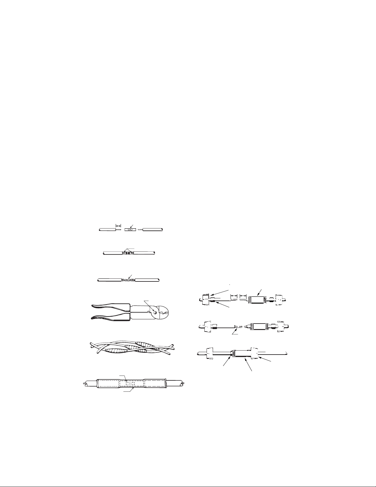
WIRE SPLICING:
1. Splice wire to motor leads. Use only copper
wire for connections to pump motor and
control box.
1. Taped splice (Wire sizes No. 8 (8.4mm
2
)
and larger):
A. Cut off motor leads. Stagger lead and
wire length so that 2nd lead is 2"
(50mm) longer than 1st lead and 3rd
lead is 2" (50mm) longer than second.
B. Match colors and lengths of wires to
colors and lengths of motor leads.
C. Trim insulation back 1/2" (13mm) from
cable ends and motor lead ends.
D.Insert motor lead ends and cable ends
into butt connector (see Figure 2). Match
wire colors between supply wires and
motor leads.
E. Using crimping pliers (Figure 5), indent
butt connector lugs.
F. Cut “Scotchfil” electrical insulation putty
into 3 equal parts and form tightly
around butt connectors. Be sure scotch-
fil overlaps insulated part of wire.
G. Using #33 Scotch tape, wrap each joint
tightly; cover wire for about 1
1
⁄2" (38mm)
on each side of joint. Make four passes
with the tape. In other words, when fin-
ished you should have four layers of
tape tightly wrapped around the wire.
Press edges of tape firmly down against
the wire (see Figure 6).
NOTICE: Since the tightly wound tape is
the only means of keeping water out of
the splice, the efficiency of the splice
will depend on the care used in wrap-
ping the tape.
NOTICE: For wire sizes larger than #8,
(7mm
2
) use a soldered joint rather than
Scotchfil putty (see Figure 4).
2. Heat-shrink splice (For wire sizes #14, 12
and 10 AWG, or 2, 3, and 5.5mm
2
):
A. Remove 3/8" (9.5mm) insulation from
ends of motor leads and power supply
wires.
B. Put plastic heat shrink tubing over motor
leads between power supply and motor
(see Figure 7).
C. Match wire colors and lengths between
power supply and motor.
D.Insert supply wire and lead ends into
butt connector and crimp (See Figures 2
and 3). Match wire colors between
power supply and motor. Pull leads to
check connections.
E. Center tubing over butt connector and
apply heat evenly with a torch (a match
or lighter will not supply enough heat).
NOTICE: Keep torch moving. Too much
concentrated heat may damage tubing
(see Figure 7).
5
COMPLETED SPLICE
1/2"
(12.7mm)
BUTT CONNECTOR
INDENT HERE
ALTERNATE METHOD
TWIST AND SOLDER
NOTCH
CONNECTOR
HEAT SHRINK TUBING
1"
2
1"
2
INSULATOR BODY
CENTERED OVER SPLICE
END CAP
GASKET
INSULATOR BODY
GASKET SLEEVE IN PLACE
CAP SCREWED ON
BUTT CONNECTOR OR
CRIMP OR SOLDER
12 7mm 12 7mm
FIGURE 2
FIGURE 3
FIGURE 4
FIGURE 5
FIGURE 6
FIGURE 7
FIGURE 8
FIGURE 9
FIGURE 10
Loading ...
Loading ...
Loading ...